MECHANICAL SPECIFICATION · 1.3 BID SUBMISSION . 1.3.1 Comply with 00100. 1.3.2 Complete the...
188
ISSUED FOR TENDER January, 2019 MECHANICAL SPECIFICATION for: STAYNER COLLEGIATE INSTITUTE BUILDING RENOVATIONS- PHASE 2 Tender # 11932T Prepared for: McKnight Charron Limited Architects 48 Alliance Blvd. Unit 10 Barrie, Ontario L4M 5K3 Prepared by: Mechanical Engineers Daycore Engineering Inc. 17 Maple Cres. Oro- Medonte, Ontario L0L 1T0
Transcript of MECHANICAL SPECIFICATION · 1.3 BID SUBMISSION . 1.3.1 Comply with 00100. 1.3.2 Complete the...

ISSUED FOR TENDER January, 2019
MECHANICAL SPECIFICATION
for:
STAYNER COLLEGIATE INSTITUTE BUILDING RENOVATIONS- PHASE 2
Tender # 11932T
Prepared for:
McKnight Charron Limited Architects 48 Alliance Blvd. Unit 10
Barrie, Ontario L4M 5K3
Prepared by:
Mechanical Engineers Daycore Engineering Inc.
17 Maple Cres. Oro- Medonte, Ontario
L0L 1T0

STAYNER COLLEGIATE INSTITUTE BUILDING RENOVATIONS – PHASE 2 Project No. 11932T SPECIFICATION INDEX
PAGE 1
SECTION TITLE NUMBER OF PAGE
Supplementary Mechanical Tender Form 5
SECTION MECHANICAL DESCRIPTION NUMBER OF PAGE
15010 General Provisions 11
15050 Basic Materials & Methods 11
15055 Testing, Adjusting and Balancing(TAB) 6
15070 Mechanical Contractor Commissioning 6
15060 Schedules 45
15250 Insulation 7
15400 Plumbing 10
15650 Refrigeration 6
15670 Air Cooled Condensing Units 5
15700 Liquid Heat Transfer 9
15800 Air Distribution 14
17010 Building Automation System 23

STAYNER COLLEGIATE INSTITUTE BUILDING RENOVATIONS - PHASE 2 Tender # 11932T DIVISION 15 Daycore Engineering Inc. SUPPLEMENTARY MECHANICAL TENDER FORM PAGE 1
DATE: __________________________________________________________________ SUBMITTED BY: ___________________________________________________________________ ADDRESS: ___________________________________________________________________ PHONE/FAX: ___________________________________________________________________ NOTE: THIS SUPPLEMENTARY MECHANICAL TENDER FORM MUST BE SUBMITTED TO THE
ARCHITECT AND ENGINEER BY EMAIL BEFORE 5:00 P.M. ON THE DAY THAT THE BID CLOSES.
Having examined a) The Drawings
b) The Specification c) The Instructions to Bidders d) Addenda One to inclusive
For the project entitled:
STAYNER COLLEGIATE INSTITUTE BUILDING RENOVATIONS- PHASE 2
As prepared by:
Mechanical Consulting Engineers Architect Daycore Engineering Inc. 17 Maple Cres. Oro-Medonte, Ont L0L 1T0 Attention: Barry Day Tel: 705-242-3128 Email [email protected]
McKnight Charron Limited Architects 48 Alliance Blvd. Unit 110 Barrie, Ont. L4M 5K3 Attention: Steve Charron Tel: 705-722-6739 x 121 Email [email protected]

STAYNER COLLEGIATE INSTITUTE BUILDING RENOVATIONS - PHASE 2 Tender # 11932T DIVISION 15 Daycore Engineering Inc. SUPPLEMENTARY MECHANICAL TENDER FORM PAGE 2
1. SUBCONTRACTORS Listed below are the names of the Subcontractors upon whose proposals this Tender is based. We recognize that the list of Subcontractors will be considered in the selection of the successful bidder. We recognize that Tenders will not be accepted unless accompanied by a complete list of Subcontractors and that no names of either of Subcontractors or "Own Forces" may be changed after submission of Tender unless good and sufficient cause is submitted in writing and written approval received from the Consultant.
LIST OF SUBCONTRACTORS
ITEM OF WORK
SUBCONTRACTOR
SUPERVISION PERSONNEL
Plumbing
HVAC Piping
Sheet Metal
Insulation
Testing & Balancing

STAYNER COLLEGIATE INSTITUTE BUILDING RENOVATIONS - PHASE 2 Tender # 11932T DIVISION 15 Daycore Engineering Inc. SUPPLEMENTARY MECHANICAL TENDER FORM PAGE 3
2. EQUIPMENT LIST We submit hereunder, a list of suppliers whose products we intend to provide. We recognize that any supplier listed will be acceptable without specific approval, provided that the supplier's name has been circled on the list. If no name is circled, the first supplier listed (for each product) will be used. We further recognize that the design has been based on the first supplier listed (for each product) and that dimensions and other characteristics of the acceptable equals may be different; and we agree to make whatever changes are necessary, in this or other trades, to accommodate these equals, at no additional cost to the Owner. Products Acceptable Suppliers
(as listed in project specification) Grilles & Diffusers Louvres
E.H. Price Nailor
Tuttle & Bailey Krueger Carnes
Metalaire Titus
Construction Specialties
KN Crowder Leo List Ruskin Ventex Nailor
Plumbing Specialties Plumbing Specialties
Jay R Smith Zurn
Enpoco Plumbing Fixtures
American Standard Crane
Eljer
Plumbing Trim
Delta American Standard
Symmons
Water Piping System Type ‘L’ Copper Viega
Air Handling Units
Trane M&I Air Systems
Daikin McQuay Vision Plus Haakon
Engineered Air Fans Cook
Temprite McQuay
Trane

STAYNER COLLEGIATE INSTITUTE BUILDING RENOVATIONS - PHASE 2 Tender # 11932T DIVISION 15 Daycore Engineering Inc. SUPPLEMENTARY MECHANICAL TENDER FORM PAGE 4
Sheldons Greenheck
Twin City Acme Penn
Howden Roof Exhausters/Intake
Greenheck Fan and Ventilator Corp Cook
Penn Ventilator Canada Ltd. Jenn Fan
Sheldons Engineering Ltd. Irving
Carnes Barry Blower
Cool Air Nailor
Radiators,Convectors & Forceflows Trane
Engineered Air Sigma
Rosemex Sterling
Slant Fin Roof Piping Supports Thaler Valves (plumbing) Kitz
Toyo/ Red White Newman Hattersley
Valves (hydronic)
Toyo / Red White Kitz
MAS Circuit Balancing Valves Tour and Anderson
Danfoss ITT Bell & Gossett
S A Armstrong
Starters Allen-Bradley Canadian Controllers
C.G.E. Cutler-Hammer

STAYNER COLLEGIATE INSTITUTE BUILDING RENOVATIONS - PHASE 2 Tender # 11932T DIVISION 15 Daycore Engineering Inc. SUPPLEMENTARY MECHANICAL TENDER FORM PAGE 5
Klockner-Moeller Siemans
Square D Westinghouse
Condensing Units and Cooling coils Daikin/ McQuay
Trane Carrier
Engineered Air
Insulation & Covering Fibreglass Knauf
Manville Roxul
3. LABOUR RATES
1. Labour rates shall be as follows and will be applied to Change Orders. These rates include all overhead and profit.
Plumbing $__________________/Hour HVAC, Pipe Fitter $__________________/Hour Sheet Metal $__________________/Hour Insulator $__________________/Hour Yours truly, ______________________________________ Print Name Signature Company

SECTION 15010 STAYNER COLLEGIATE INSTITUTE BUILDING RENOVATIONS – PHASE 2 Tender # 11932T GENERAL PROVISIONS INDEX
ARTICLE PAGE NO.
1.1 GENERAL .......................................................................................................................................... 1
1.2 CODES AND STANDARDS ............................................................................................................... 1
1.3 BID SUBMISSION .............................................................................................................................. 1
1.4 SPECIFIED EQUIVALENT AND ALTERNATIVE APPARATUS AND MATERIALS.......................... 1
1.5 DOCUMENTS .................................................................................................................................... 2
1.6 DETAIL DRAWINGS AND INSTRUCTIONS ..................................................................................... 2
1.7 SHOP DRAWINGS ............................................................................................................................ 2
1.8 APPLIANCES ..................................................................................................................................... 3
1.9 CORRECTION AFTER COMPLETION ............................................................................................. 3
1.10 PROTECTION OF WORK AND PROPERTY ................................................................................ 3
1.11 CERTIFICATES AND PAYMENTS ................................................................................................ 3
1.12 CLEANING UP................................................................................................................................ 3
1.13 EXAMINATION ............................................................................................................................... 3
1.14 OFFICE AND STORAGE ............................................................................................................... 4
1.15 SUPERINTENDENT ....................................................................................................................... 4
1.16 CO-ORDINATION ........................................................................................................................... 4
1.17 CO-ORDINATION WITH CEILING AND WALL PATTERNS ......................................................... 4
1.18 SCAFFOLDING, SHORING, RIGGING AND HOISTING ............................................................... 4
1.19 CHANGES OR REVISIONS TO THE WORK ................................................................................ 4
1.20 EXISTING UNDERGROUND SERVICES ...................................................................................... 5
1.21 TEMPORARY HEATING ................................................................................................................ 5
1.22 TEMPORARY AND TRIAL USAGE ................................................................................................ 5
1.23 DRAWINGS .................................................................................................................................... 6
1.24 RECORD DRAWINGS ................................................................................................................... 6
1.25 DATA BOOK ................................................................................................................................... 6
1.26 COMMISSIONING AND DEMONSTRATION ................................................................................ 7

SECTION 15010 STAYNER COLLEGIATE INSTITUTE BUILDING RENOVATIONS – PHASE 2 Tender # 11932T GENERAL PROVISIONS INDEX
1.27 COMMISSIONING PROCESS ALLOCATION ............................................................................... 7
1.28 OWNER’S DEMONSTRATION ...................................................................................................... 7
1.29 FINAL INSPECTION ....................................................................................................................... 8
1.30 REMOVALS .................................................................................................................................... 8
1.31 TIME PERIODS FOR WORK IN EXISTING BUILDING ................................................................ 9
1.32 EQUIPMENT DELIVERIES ............................................................................................................ 9

SECTION 15010 STAYNER COLLEGIATE INSTITUTE BUILDING RENOVATIONS – PHASE 2 Tender # 11932T GENERAL PROVISIONS PAGE 1
PART 1 - GENERAL
1.1 GENERAL
1.1.1 This Section of the Specification is an integral part of the Contract Documents and shall be read accordingly.
1.1.2 Comply with Division 1 - General Requirements - and all documents referred to therein.
1.1.3 The General Conditions of the Contract, the Supplementary General Conditions, and General Requirements shall form part of this Specification as though written in full herein.
1.2 CODES AND STANDARDS
1.2.1 Design, specifications and installation must comply with latest editions and all amendments of the following codes and standards. Where conflicts in requirements occur the higher standard will apply: • American Society of Heating, Refrigeration, ASHRAE 90.1. • Canadian Standards Association Standards. • Air Movement and Control Association Standards; • Canadian Gas Association Standards; • NFPA Fire Codes; • Ontario Building Code • All governing municipal requirements; • Canadian Heating, Ventilating and Air Conditioning Code; • Canadian Plumbing Code; • Underwriters' Laboratories of Canada Standards;
1.3 BID SUBMISSION 1.3.1 Comply with 00100.
1.3.2 Complete the Supplementary Mechanical Tender Form and submit to the Engineer by 5:00 PM on the day the Bid closes.
1.3.3 Section 17010-‘Building Automation Systems’ shall bid directly to the Mechanical Contractors.
1.4 SPECIFIED EQUIVALENT AND ALTERNATIVE APPARATUS AND MATERIALS
1.4.1 Tenders shall be prepared only on the basis of specified material and equipment.
1.4.2 If materials or apparatus manufactures and/or specified by a manufacturer named as equivalent are used in lieu of the manufacturer specified, be responsible for ensuring that the substituted material or apparatus is equivalent in performance and operating characteristics to the specified materials or apparatus, and, it shall be understood that all costs for larger starters, additional space, larger power feeders and changes to associated or adjacent work will be borne by the subcontractor offering the substitution. In addition, in Equipment Rooms where apparatus named as equivalent is used in lieu of specified apparatus and the dimensions of such apparatus differs from the specified apparatus, prepare and submit for approval, accurately dimensioned layouts of rooms affected.
1.4.3 In addition to the manufacturers specified or named as equivalent, you may propose alternative manufacturers of equipment and\or apparatus to the client for

SECTION 15010 STAYNER COLLEGIATE INSTITUTE BUILDING RENOVATIONS – PHASE 2 Tender # 11932T GENERAL PROVISIONS PAGE 2
acceptance, listing in each case a corresponding credit for each alternative proposed. However, your tender price must be based on apparatus or materials specified or named as equivalent. Certify in writing to the Consultant that the alternative meets all space, power, design and all other requirements of the specified or equivalent material or apparatus. In addition, it shall be understood that all costs for larger starters, space, power feeders, and changes to associated equipment, mechanical and/or electrical, required by acceptance of proposed alternatives, will be borne by the party making the proposal.
1.4.4 Unless otherwise noted, all materials and apparatus shall be new.
1.4.5 The Contractor shall pay the Consultant on a per diem basis (hourly) for the review of the alternate equipment supplier to verify conformance with the Contract Documents.
1.5 DOCUMENTS 1.5.1 This Division of the Specification has generally been divided into Trade Sections. It
is not thereby intended to recognize, set or define limits to any sub-trade contractor or restrict the Contractor in letting subcontracts. Neither is the Contractor relieved of responsibility for completion of Contract whether sublet or not.
1.5.2 The sentence in the General Conditions: "Specifications shall govern over Drawings", shall not apply to this Division. Where conflict does occur between codes, Specifications and Drawings, plan and riser, the maximum condition shall govern, and the Tender shall be based on whichever indicates the greater cost.
1.6 DETAIL DRAWINGS AND INSTRUCTIONS 1.6.1 Submit notification of locations where installation of fixtures, fittings, and equipment
would interfere with interior treatment and use of building. Detail drawings or instructions will then be issued.
1.7 SHOP DRAWINGS 1.7.1 Submit shop drawings, unless otherwise specified, by email in PDF’s for each major
item of equipment such as plumbing fixtures, pumps, air moving units, radiation, coils, grilles, diffusers, heating and cooling equipment. Combine the shop drawings as much as possible into each email.
1.7.2 Manufacturer's printed data sheets for standard items are acceptable providing pertinent characteristics are identified and relate to specified items.
1.7.3 Note each shop drawing with the following information: • Manufacturer's and Supplier's name. • Catalogue model number. • Name of trade supplying item. • Project identification number.
1.7.4 Each shop drawing shall be checked and stamped as being correct, by trade purchasing item, and by Contractor, before drawing is submitted. If above requirements are not complied with, shop drawings will be rejected and returned forthwith.

SECTION 15010 STAYNER COLLEGIATE INSTITUTE BUILDING RENOVATIONS – PHASE 2 Tender # 11932T GENERAL PROVISIONS PAGE 3
1.8 APPLIANCES 1.8.1 Provide any extension cords, lamps and miscellaneous materials, temporarily
required for carrying out work.
1.9 CORRECTION AFTER COMPLETION
1.9.1 Submit a written guarantee to Owner covering the remedy of defects in the Work at completion of Work but before issue of final certificate. This guarantee shall in no way supplant any other guarantee of longer period called for on certain equipment or materials.
1.9.2 Submit a similar written guarantee for one year from date of acceptance for any part of Work accepted by Owner, before completion of whole Work.
1.10 PROTECTION OF WORK AND PROPERTY
1.10.1 Each trade shall protect its own and other trade's finished and unfinished work from damage, due to the carrying out of its work. Cover floors and other work with tarpaulins, if required, for this purpose. Each trade shall assume responsibility for repairing damage to floor and wall surfaces resulting from its failure to provide such protection. Carry out such repairs in a satisfactory manner without expense to Owner.
1.11 CERTIFICATES AND PAYMENTS
1.11.1 Arrange and pay for permits, tests, certificates of inspection and street connections required for the Work. Submit applications requiring Owner's signature before commencing Work. Do Work in compliance with laws, rules, ordinances and regulations having jurisdiction.
1.11.2 Inspection certificates, as follows, shall be submitted before final certificates will be issued:
• Electrical Inspection( ESA Certificate) • Plumbing Inspection
1.11.3 Renew Department of Labour certificates, if necessary, to remain in force for the full guarantee period.
1.12 CLEANING UP 1.12.1 Assume responsibility for removing tools and waste materials on completion of Work
and leave Work in clean and perfect condition.
1.13 EXAMINATION 1.13.1 Carefully examine any existing buildings, local conditions affecting the Work and
building site, together with the Architectural, Structural and Electrical Drawings to make sure that Work under Specification and as shown on Drawings can be satisfactorily carried out without changes. Work of all trade Divisions shall be examined, before commencing Work, and any defect or interference affecting Work shall be reported at once.
1.13.2 No allowance will be made for any expense incurred through failure to make these examinations or on account of any condition of site or any growth or item existing thereon which was visible or known to exist at time Tender for Work was submitted.

SECTION 15010 STAYNER COLLEGIATE INSTITUTE BUILDING RENOVATIONS – PHASE 2 Tender # 11932T GENERAL PROVISIONS PAGE 4
1.14 OFFICE AND STORAGE 1.14.1 Provide temporary office, workshop and tools and material storage space for the
Work and assume responsibility for any loss or damage thereto. Buildings erected for this purpose shall conform in appearance to those erected for similar purposes under other Divisions of Specification. Provide heat, light and telephone for the buildings.
1.15 SUPERINTENDENT 1.15.1 Provide a full time Superintendent to oversee and coordinate all sub-trades in
Division 15.
1.16 CO-ORDINATION 1.16.1 Work of each trade shall be laid out so that it does not conflict with Work under other
Divisions of Specification. Make good damage to Owner's property or other trade's work, caused by improper locating or carrying out of Work.
1.16.2 Prepare field drawings, based on manufacturer's shop drawings, whenever necessary to show location of major equipment and relative position of various services. Arrange layouts with due regard to maintenance. Obtain approval of these field drawings before proceeding with work involved thereon. Draw field drawings to a scale of 1 to 50 metric.
1.16.3 Install services and equipment which are to be concealed, as close as possible to building structure so that necessary furring can be kept to minimum dimensions.
1.17 CO-ORDINATION WITH CEILING AND WALL PATTERNS
1.17.1 Locate wall and ceiling diffusers in exact accordance with dimensions furnished by the ceiling installer, wall finish installer, masonry installer and Consultant. Make any necessary adjustments in duct branches to allow diffusers to coincide with ceiling and wall patterns.
1.18 SCAFFOLDING, SHORING, RIGGING AND HOISTING
1.18.1 Provide scaffolding and shoring necessary for other work of this Division. Scaffolding and shoring shall be adequate to protect the workmen according to Provincial and Local Regulations.
1.18.2 Provide rigging and millwrighting, labour and equipment necessary for the work of this Division. Employ only workmen well experienced and skilled in such trades for this portion of the work.
1.18.3 Provide hoisting machinery, operators, labour and materials necessary to lift and place equipment installed under this Division.
1.19 CHANGES OR REVISIONS TO THE WORK
1.19.1 Whenever the Consultant proposes, in writing, to make a change or revisions in the design, arrangement quantity or type of any of the work from that called for on or in the contract documents, submit to the Consultant for approval, a detailed itemized breakdown of the cost of all apparatus, materials and labour entering into each change or revision.
1.19.2 Supply itemized breakdown of the actual cost of the material to the Contractor. Submit invoices to the Consultant when requested. Labour rates and hours shall be

SECTION 15010 STAYNER COLLEGIATE INSTITUTE BUILDING RENOVATIONS – PHASE 2 Tender # 11932T GENERAL PROVISIONS PAGE 5
itemized and based on the Mechanical Contractors Association schedule with an applied factor of 70%.
1.19.3 Do not execute any changes or revisions until written approval and authorization for such changes or revisions has been obtained from the Consultant.
1.19.4 Incorporate executed change orders into as-built drawings and maintenance manuals.
1.20 EXISTING UNDERGROUND SERVICES
1.20.1 Before commencement of excavation of the Work, determine with the Consultant, the municipalities and utilities, the presence of existing underground services at the site and verify satisfactory condition.
1.20.2 Locate such services and mark out same. Ensure that all trades concerned are aware of their presence.
1.21 TEMPORARY HEATING 1.21.1 Temporary heating required while building is under construction will be provided
under Division 1. Permanent heating units and radiation may be used for temporary heat by General Contractor, providing this equipment is installed in its permanent location and providing that building is completely closed in.
1.21.2 Hot water boilers may not be used unless heating units, radiation and piping thereto, constituting the permanent heating system, are completely installed and connected to boiler in an approved manner. Hot water boilers used for temporary heating shall have approved chemical water treatment.
1.21.3 Contractor under Division 1 will be responsible for the operation, care and maintenance of the permanent heating system when used for temporary heating. Permanent heating equipment used for temporary heating will be thoroughly cleaned and put in first class approved operating condition and appearance by the General Contractor at completion of job and prior to final acceptance by Owner. Damaged equipment and piping will be replaced by General Contractor in an approved manner.
1.22 TEMPORARY AND TRIAL USAGE
1.22.1 Temporary and trial usage by Owner of any mechanical or electrical device, machinery, apparatus, equipment or any other work or materials supplied before final completion and written acceptance shall not be construed as evidence of acceptance of same by Owners.
1.22.2 Owners shall have the privilege of such temporary and trial usage, as soon as Contractor shall claim that said work is completed and in accordance with Drawings and Specifications, for such reasonable length of time as is deemed to be sufficient for making a complete and thorough test of same. Claims for damage shall not be made by Contractor for the injury to or breaking of any parts of such work which may be used, whether caused by weakness or inaccuracy of structural parts or by defective materials or workmanship of any kind whatsoever.

SECTION 15010 STAYNER COLLEGIATE INSTITUTE BUILDING RENOVATIONS – PHASE 2 Tender # 11932T GENERAL PROVISIONS PAGE 6
1.23 DRAWINGS 1.23.1 Drawings showing the Work do not show every structural detail and are
diagrammatic only. Take any information involving accurate measurements of building from Architectural Drawings or at building.
1.23.2 Equipment dimensions are based on the first or top named manufacturer. Dimensions of items by other listed manufacturers shall not exceed variable space with necessary allowance for service and maintenance.
1.23.3 Make necessary change to runs of piping, ductwork and raceways to accommodate structural conditions. Location of pipes, ductwork, raceways and equipment may be altered without additional charge or expense to Owner providing such change is made before installation of items involved. Such changes will be authorized by ratified site instructions and shall be recorded on Record Set of Drawings.
1.23.4 The general location and route to be followed by pipes and ductwork is indicated on Drawings. Install these items to conserve headroom and interfere as little as possible with the free use of space through which they pass.
1.24 RECORD DRAWINGS 1.24.1 An extra set of white prints of Drawings for Work will be supplied. Mark on these
Drawings in coloured ink every change and deviation from runs of piping, ductwork, conduit and other services as originally shown so that, on completion of job, they will constitute a record of exact locations of those services as installed. Keep these Drawings in the site office and keep them up-to-date. Final certificate of job acceptance will not be issued until these Drawings are completed and submitted.
1.24.2 Dimension locations of drains, pipes, ductwork, conduit, manholes, foundations and similar buried items, with respect to building column centres. Mark levels with respect to an elevation which will be provided.
1.24.3 Obtain drawings on a flash drive.
1.24.4 On completion of work, transfer the information onto the flash drive and submit including the CAD files and the PDF’s to the Consultant for review.
1.24.5 Correct the information as directed and hand the flash drive over to the Owner together with a set of white prints.
1.25 DATA BOOK 1.25.1 Submit one hard copy of manufacturer's operating and maintenance instructions,
bound in vinyl covered hard backed, 8 1/2" x 11" size, three-ring covers at completion, and before final acceptance, of Work. Contents of book shall not include handwritten data. Also transfer the data book information on a flash drive in PDF form.
1.25.2 Title sheet, in each book shall be labelled "Manufacturers' Data Book" and shall bear the following:
• Project Name • Date • List of Contents
1.25.3 Each book shall contain the following: • Manufacturer's literature, parts list, approved shop drawing, and name and
address of closest service organization and spare parts source, for each item of equipment.
• Voltage and ampere rating for each item of electrical equipment. Note:

SECTION 15010 STAYNER COLLEGIATE INSTITUTE BUILDING RENOVATIONS – PHASE 2 Tender # 11932T GENERAL PROVISIONS PAGE 7
Suitably fold shop drawings larger than 8 1/2" x 11" and place in a manila envelope, 3-hole punched, for inclusion in book.
• Description of system. • Schematic drawings for electrical, ventilating, heating and plumbing
systems. Mount one set of schematic drawings in a glazed frame in the mechanical room.
• Description of summer operations. • Description of winter operations. • Controls including diagrams. • Maintenance and oil schedule. • Type of oil and grease to be used on each piece of equipment. • Method of operation for each piece of equipment, and list of equipment with
replacement parts, part number, suppliers, addresses etc. • Valve Charts. • Air and Water Balancing Reports. • Contractor warranty and equipment extended warranties.
1.25.4 Review data book with Owner's operating staff or representatives to ensure a thorough understanding of each item of equipment and its operation.
1.26 COMMISSIONING AND DEMONSTRATION 1.26.1 Commissioning is the activation of the completed installation to complete working
order at the specified requirements as certified by the Consultant. Refer to Section 15070.
1.26.2 Be responsible for the installation and performance of all Work provided under this Division.
1.26.3 The School Board will retain the services of an independent Commissioning Agency to commission the project. This Division shall cooperate and provide assistance to the Commissioning Agent as required to perform commissioning. Make labour available for the duration of the commissioning work.
1.27 COMMISSIONING PROCESS ALLOCATION 1.27.1 Commissioning process shall be allocated a value equal to 8% of the contract. The
contractors may draw from this allocation as the commissioning process is completed.
1.27.2 The contractors shall submit all test and verification forms. The Consultant will use these forms to calculate percentage complete.
1.27.3 The contractor may claim up to 5% of the contract from this allocation leading up to performance testing. The remaining 3% shall not be paid out until the performance testing, O & M manuals and training have been completed satisfactorily
1.28 OWNER’S DEMONSTRATION 1.28.1 Demonstrate to the Owner and Consultant the operation of all systems when
commissioning has been completed. Demonstration will include the following:
1.28.1.1 Operation of all automatic control dampers and temperature control devices (Division 17).
1.28.1.2 Response of all terminal units to thermostats and other controls (Division 17).
1.28.1.3 Location of and operation of all access panels.

SECTION 15010 STAYNER COLLEGIATE INSTITUTE BUILDING RENOVATIONS – PHASE 2 Tender # 11932T GENERAL PROVISIONS PAGE 8
1.28.1.4 Location of all valves and control devices above ceilings.
1.28.1.5 Location and operability of fire dampers.
1.28.1.6 Noise levels of all mechanical equipment and terminal devices under maximum operating conditions. Refer to Section 15200 for acceptable level of sound ratings.
1.28.1.7 Operation of all equipment and systems under each mode of operation.
1.28.2 At the completion of commissioning, testing, balancing and demonstration submit the following to the Consultant:
1.28.2.1 Letter certifying that all work specified is complete, clean and operational in accordance with the Contract Documents.
1.28.2.2 As-built documents.
1.28.2.3 All inspection authorities approvals.
1.28.3 Provide a sequence of operation for seasonal switch-over (heating/cooling) of systems indicating valves to be normally open or closed.
1.28.4 If field tests show deficient equipment, independent test of the equipment may be requested by Consultant. If the equipment does not conform to Specifications be responsible for all tests, corrective action and retesting and balancing
1.29 FINAL INSPECTION 1.29.1 Refer to Division 1 regarding the "Contract Close Out".
1.29.2 Request in writing for a final inspection of mechanical and electrical systems.
1.29.3 Do not submit this written request until: • deficiencies noted during job inspections have been completed. • systems have been balanced and tested and are ready for operation. • balancing reports have been submitted and approved. • completed data books have been submitted and approved. • tags are in place, valve charts and line diagrams have been submitted and
approved, and equipment identification is completed. • the cleaning up is finished in every respect. • spare parts and replacement parts specified have been provided and receipt
of same acknowledged. • record drawings are completed and approved.
1.30 REMOVALS
1.30.1 Disconnect and remove materials and equipment indicated on the plans to be removed and/or relocated.
1.30.2 Turn over designated equipment to the Owner as indicated on the drawings. Confirm with the School Board whether the Maintenance wants the existing glycol pumps prior to disposal. Dispose of unwanted materials and equipment.

SECTION 15010 STAYNER COLLEGIATE INSTITUTE BUILDING RENOVATIONS – PHASE 2 Tender # 11932T GENERAL PROVISIONS PAGE 9
1.31 TIME PERIODS FOR WORK IN EXISTING BUILDING
1.31.1 All work in the existing Building is to be performed in such a manner as to not disrupt the normal operations. The existing building will be fully occupied during construction.
1.31.2 All systems are to be kept fully functional. Provide any temporary measures to comply with this requirement.
1.31.3 Note that any noise generating works that disrupt the Building operation will not be permitted.
1.31.4 Phasing of the work relating to the new water service and electrical service shall be specified in the Architect’s specifications since they will require shutting school down for up to two weeks.
1.32 EQUIPMENT DELIVERIES
1.32.1 Confirm with all equipment manufactures prior to ordering that delivery will meet the completion schedule.
1.32.2 Submit a delivery schedule within 30 days of receipt of the contract.
END OF SECTION 15010
SECTION 15050 STAYNER COLLEGIATE INSTITUTE BUILDING RENOVATIONS – PHASE 2 Tender # 11932T BASIC MATERIALS & METHODS PAGE 1
ARTICLE PAGE NO.
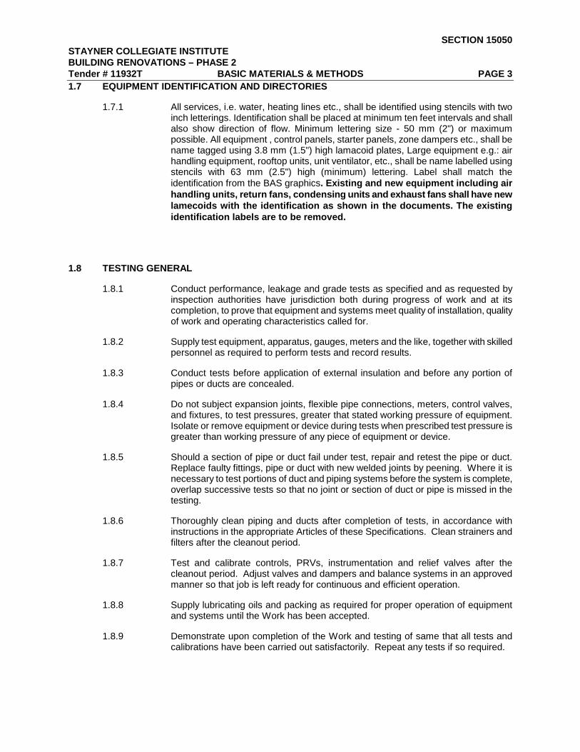
PART 1 - GENERAL ............................................................................................................................... 1
1.1 REFERENCE ..................................................................................................................................... 1
1.2 WORK INCLUDED ............................................................................................................................. 1
1.3 STANDARD OF MATERIALS ............................................................................................................ 1
1.4 CUTTING AND PATCHING ............................................................................................................... 1
1.5 PAINTING .......................................................................................................................................... 1
1.6 EXCAVATION AND BACKFILL .......................................................................................................... 2
1.7 EQUIPMENT IDENTIFICATION AND DIRECTORIES ...................................................................... 3
1.8 TESTING GENERAL .......................................................................................................................... 3
1.9 TESTING PLUMBING ........................................................................................................................ 4
1.10 TESTING DUCTWORK .................................................................................................................. 4
1.11 SLEEVES AND FLOOR PLATES ................................................................................................... 4
1.12 SUPPORTS AND BASES............................................................................................................... 5
1.13 PIPE HANGERS ............................................................................................................................. 5
1.14 ACCESS DOORS ........................................................................................................................... 7
1.15 MAINTENANCE OF BEARINGS .................................................................................................... 7
1.16 ELECTRIC MOTORS - HIGH EFFICIENCY................................................................................... 7
1.17 STARTERS ..................................................................................................................................... 8
1.18 FUSES FOR MOTOR PROTECTION ............................................................................................ 9
1.19 WIRING FOR MECHANICAL ......................................................................................................... 9
1.20 SPARE PARTS AND TOOLS ....................................................................................................... 10

SECTION 15050 STAYNER COLLEGIATE INSTITUTE BUILDING RENOVATIONS – PHASE 2 Tender # 11932T BASIC MATERIALS & METHODS PAGE 1
PART 1 - GENERAL
1.1 REFERENCE
1.1.1 This Section of the Specification is an integral part of the Contract Documents and shall be read accordingly.
1.1.2 Comply with Division 1 - General Requirements - and all documents referred to therein.
1.1.3 Conform to the requirements of Section 15010 Mechanical General Provisions.
1.2 WORK INCLUDED
1.2.1 Work to be done under this Section shall include furnishing labour, materials and equipment required for installation, testing and putting into proper operation complete Mechanical systems as shown, as specified and otherwise required.
1.3 STANDARD OF MATERIALS
1.3.1 Materials and equipment are specifically described and named in this Specification in order to establish a standard of material and workmanship.
1.3.2 Materials required for performance of work shall be new and the best of their respective kinds and of uniform pattern throughout work.
1.3.3 Materials shall bear approval labels as required by Code and/or Inspection Authorities.
1.3.4 Install materials in strict accordance with manufacturers' recommendations.
1.3.5 Include items of material and equipment not specifically noted on Drawings or mentioned in Specifications but which are necessary to make a complete and operating installation.
1.4 CUTTING AND PATCHING
1.4.1 Cutting and patching of new work to accommodate the work, unless otherwise noted, will be done by the General Contractor, but shall be arranged and paid for by the trade requiring same. Layout such work for approval before undertaking same.
1.4.2 Each trade shall assume responsibility for prompt installation of its work in advance of concrete pouring or similar work. Should any cutting or repairing of either unfinished or finished work be required because such installation was not done, trade responsible shall employ the particular trade, whose work is involved, to do such cutting and patching and shall pay for any resulting costs. Layout such work for approval before undertaking same.
1.5 PAINTING
1.5.1 All finish painting will be done under the Painting Division 9 of these specifications except where such pieces of equipment of material that require shop painting or finishing by the manufacturer, or as specified below. Clean and leave surfaces ready for Painter.
1.5.2 Where equipment is delivered with the final paint or finish applied by the manufacturer, repaint or refinish surfaces damaged during erection or shipment, so as to match the original surface and be unobtrusive.

SECTION 15050 STAYNER COLLEGIATE INSTITUTE BUILDING RENOVATIONS – PHASE 2 Tender # 11932T BASIC MATERIALS & METHODS PAGE 2
1.5.3 All structural steel including hangers, brackets, supports and other ferrous metals shall be shop or factory prime painted wherever practicable. Wherever structural steel including hangers, brackets, supports, and other ferrous metal cannot be shop or factory prime painted, wire brush to remove all traces of rust, clean off all traces of dirt, oil and grease, and apply one coat of an approved rust inhibiting primer in accordance with CGSB-GB-40d and leave ready to receive finish paint.
1.5.4 Equipment not finished shall be provided with one shop coat of primer paint.
1.5.5 All black iron/steel pipework and steel fitting shall be delivered to site undamaged and free from dirt, rust, and protected by factory applied prime paint.
1.5.6 Touch up all bolt heads, nuts, threads and previously unpainted connections. Touch up all damaged and braised areas on pipework and steel after erection, and wire brush all welds and cut ends. Apply one coat of an approved rust inhibiting primer in accordance with CGSB-GP-40d and leave ready to receive finish paint.
1.5.7 Paint visible portions of ductwork behind grilles with one coat flat black paint.
1.6 EXCAVATION AND BACKFILL
1.6.1 Excavate and backfill as required for the work, both inside and outside the building in accordance with Part 2, "Excavating and Backfilling for Structures" and as further specified herein.
1.6.2 Existing underground services and other services are indicated on the floor plans, location of which has been taken from all available information and is assumed to be correct.
1.6.3 Form bottoms of trenches inside building so that pipes are supported on a solid bed of undisturbed earth. Care shall be taken to relieve hubs of undue strain.
1.6.4 Carefully form bottoms of trenches both inside and outside building where no special bedding is required, to give support to at least lower 1/3 of outside circumference of pipe.
1.6.5 Support piping passing through building foundation walls or concrete supports as further specified.
1.6.6 Thoroughly tamp sand around and over pipes in 150 mm layers to a height of at least 600 mm above top of pipes and water as necessary. Fill remainder of trench and consolidate in one foot layers with approved excavated material, free from stone and water, as required..
1.6.7 Flushing and Testing
1.6.8 Flush all sewers at the completion of the work. No sewer will be inspected either for preliminary or final approval before thorough cleaning.
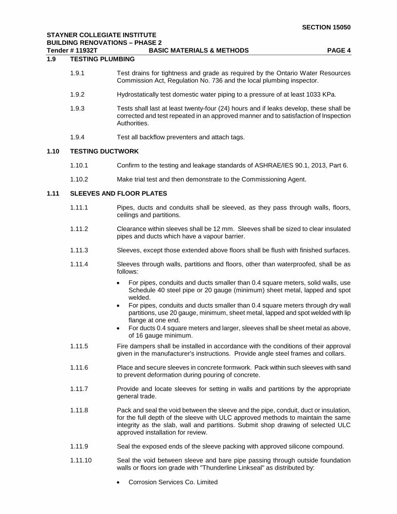
SECTION 15050 STAYNER COLLEGIATE INSTITUTE BUILDING RENOVATIONS – PHASE 2 Tender # 11932T BASIC MATERIALS & METHODS PAGE 3 1.7 EQUIPMENT IDENTIFICATION AND DIRECTORIES
1.7.1 All services, i.e. water, heating lines etc., shall be identified using stencils with two inch letterings. Identification shall be placed at minimum ten feet intervals and shall also show direction of flow. Minimum lettering size - 50 mm (2") or maximum possible. All equipment , control panels, starter panels, zone dampers etc., shall be name tagged using 3.8 mm (1.5") high lamacoid plates, Large equipment e.g.: air handling equipment, rooftop units, unit ventilator, etc., shall be name labelled using stencils with 63 mm (2.5") high (minimum) lettering. Label shall match the identification from the BAS graphics. Existing and new equipment including air handling units, return fans, condensing units and exhaust fans shall have new lamecoids with the identification as shown in the documents. The existing identification labels are to be removed.
1.8 TESTING GENERAL
1.8.1 Conduct performance, leakage and grade tests as specified and as requested by inspection authorities have jurisdiction both during progress of work and at its completion, to prove that equipment and systems meet quality of installation, quality of work and operating characteristics called for.
1.8.2 Supply test equipment, apparatus, gauges, meters and the like, together with skilled personnel as required to perform tests and record results.
1.8.3 Conduct tests before application of external insulation and before any portion of pipes or ducts are concealed.
1.8.4 Do not subject expansion joints, flexible pipe connections, meters, control valves, and fixtures, to test pressures, greater that stated working pressure of equipment. Isolate or remove equipment or device during tests when prescribed test pressure is greater than working pressure of any piece of equipment or device.
1.8.5 Should a section of pipe or duct fail under test, repair and retest the pipe or duct. Replace faulty fittings, pipe or duct with new welded joints by peening. Where it is necessary to test portions of duct and piping systems before the system is complete, overlap successive tests so that no joint or section of duct or pipe is missed in the testing.
1.8.6 Thoroughly clean piping and ducts after completion of tests, in accordance with instructions in the appropriate Articles of these Specifications. Clean strainers and filters after the cleanout period.
1.8.7 Test and calibrate controls, PRVs, instrumentation and relief valves after the cleanout period. Adjust valves and dampers and balance systems in an approved manner so that job is left ready for continuous and efficient operation.
1.8.8 Supply lubricating oils and packing as required for proper operation of equipment and systems until the Work has been accepted.
1.8.9 Demonstrate upon completion of the Work and testing of same that all tests and calibrations have been carried out satisfactorily. Repeat any tests if so required.
SECTION 15050 STAYNER COLLEGIATE INSTITUTE BUILDING RENOVATIONS – PHASE 2 Tender # 11932T BASIC MATERIALS & METHODS PAGE 4 1.9 TESTING PLUMBING
1.9.1 Test drains for tightness and grade as required by the Ontario Water Resources Commission Act, Regulation No. 736 and the local plumbing inspector.
1.9.2 Hydrostatically test domestic water piping to a pressure of at least 1033 KPa.
1.9.3 Tests shall last at least twenty-four (24) hours and if leaks develop, these shall be corrected and test repeated in an approved manner and to satisfaction of Inspection Authorities.
1.9.4 Test all backflow preventers and attach tags.
1.10 TESTING DUCTWORK
1.10.1 Confirm to the testing and leakage standards of ASHRAE/IES 90.1, 2013, Part 6.
1.10.2 Make trial test and then demonstrate to the Commissioning Agent.
1.11 SLEEVES AND FLOOR PLATES
1.11.1 Pipes, ducts and conduits shall be sleeved, as they pass through walls, floors, ceilings and partitions.
1.11.2 Clearance within sleeves shall be 12 mm. Sleeves shall be sized to clear insulated pipes and ducts which have a vapour barrier.
1.11.3 Sleeves, except those extended above floors shall be flush with finished surfaces.
1.11.4 Sleeves through walls, partitions and floors, other than waterproofed, shall be as follows:
• For pipes, conduits and ducts smaller than 0.4 square meters, solid walls, use Schedule 40 steel pipe or 20 gauge (minimum) sheet metal, lapped and spot welded.
• For pipes, conduits and ducts smaller than 0.4 square meters through dry wall partitions, use 20 gauge, minimum, sheet metal, lapped and spot welded with lip flange at one end.
• For ducts 0.4 square meters and larger, sleeves shall be sheet metal as above, of 16 gauge minimum.
1.11.5 Fire dampers shall be installed in accordance with the conditions of their approval given in the manufacturer's instructions. Provide angle steel frames and collars.
1.11.6 Place and secure sleeves in concrete formwork. Pack within such sleeves with sand to prevent deformation during pouring of concrete.
1.11.7 Provide and locate sleeves for setting in walls and partitions by the appropriate general trade.
1.11.8 Pack and seal the void between the sleeve and the pipe, conduit, duct or insulation, for the full depth of the sleeve with ULC approved methods to maintain the same integrity as the slab, wall and partitions. Submit shop drawing of selected ULC approved installation for review.
1.11.9 Seal the exposed ends of the sleeve packing with approved silicone compound.
1.11.10 Seal the void between sleeve and bare pipe passing through outside foundation walls or floors ion grade with "Thunderline Linkseal" as distributed by:
• Corrosion Services Co. Limited

SECTION 15050 STAYNER COLLEGIATE INSTITUTE BUILDING RENOVATIONS – PHASE 2 Tender # 11932T BASIC MATERIALS & METHODS PAGE 5 1.12 SUPPORTS AND BASES
1.12.1 Supply and erect special structural required for the installation of mechanical equipment. Provide anchor bolts and other fastenings unless noted otherwise. Mount equipment required to be suspended above floor level, where details are not shown, on a frame or platform bracketed from the wall or suspended from the ceiling. Carry supports to either the ceiling or the floor, or both as required, at locations where, because wall thickness is inadequate, it is not permitted to use such brackets.
1.12.2 Concrete bases and housekeeping pads for mechanical and electrical equipment, which are in direct contact with the floor slab, will be provided under Concrete Division No. 3. Submit drawings to Concrete Division giving dimensions and requirements.
1.12.3 Concrete pads shall be set on the slab and shall be 100 mm high above the slab. Edges of pads are to be chamfered (25 mm). Generally pads shall be 160 mm larger than base of the equipment being supportedProvide concrete bases for all mechanical equipment unless otherwise shown. Provide a 100mm raised curb around all ductwork and piping penetrating the floor of Mechanical Rooms.
1.12.4 Support hangers, in general, form inserts in concrete construction or from building structural steel beams, using beam clamps. Provide additional angle or channel steel members, required between beams for supporting pipes and conduits.
1.12.5 Do not use explosive drive pins in any section of Work.
1.13 PIPE HANGERS
1.13.1 Provide pipe hangers, and their supports, for piping. Install hanger rods vertically, without bends or offsets, and so that finished piping is true with respect to both line and grade.
1.13.2 Hang or support horizontal cast iron drainage piping at every hub. Hangers shall properly fit outside diameter of pipe. Hangers shall be Clevis type and shall be as manufactured by:
• E. Myat & Co. Ltd. - Fig. 126 • Grinnell Co. of Canada Ltd. • Fig. 260 for soil pipe • Fig. 590 for C.I. pressure pipe
1.13.3 Hang or support horizontal plumbing piping, other than cast iron drainage, as follows:
• Up to and including 19 mm size 1.8 m maximum intervals • Size 25 mm and above 2.4 m maximum intervals
1.13.4 Horizontal piping, for service other than plumbing shall have maximum support space as follows:

SECTION 15050 STAYNER COLLEGIATE INSTITUTE BUILDING RENOVATIONS – PHASE 2 Tender # 11932T BASIC MATERIALS & METHODS PAGE 6
1.13.5 Spacing where pipes are grouped shall satisfy the smallest size pipe.
1.13.6 Hangers, for piping, other than cast iron drainage unless otherwise specified, shall be Clevis type as manufactured by:
• E. Myatt & Co. Ltd. - Fig. 124 for uninsulated piping - Fig. 124L for insulated hot piping - Fig. 125 for heavy duty uninsulated piping - Fig. 125L for heavy duty insulated hot piping - Fig. 125 or 125 for hangers sized to suit O.D. of insulation for cold
piping.
• Grinnell Co. of Canada Ltd. - Fig. 260 for uninsulated piping - Fig. 300 for insulated hot piping - Fig 260 for hanger sized to suit O.D. of insulation for cold piping.
1.13.7 Hangers, for copper or brass piping not being used for domestic cold water service, shall be copper plated or plastic coated, as manufactured by:
• E. Myatt & Co. - Fig. 152CT • Grinnell Co. of Canada Ltd. - Fig. 97-C
1.13.8 Support vertical cast iron drainage piping, including soil, waste, vent stacks, and rainwater leaders at hubs by a riser clamp located at every other floor slab. Bolt riser clamps around pipe and anchor to concrete slab. Riser clamps shall be as manufactured by:
• E. Myatt & Co. - Fig. 182 • Grinnell Co. of Canada Ltd. - Fig. 261
1.13.9 Hangers, installed under domestic cold water piping shall be large enough to go completely around covering and provide a metal protector at the hanger from the insulation.
NOM. PIPE SIZE (MM)
MAX. SPAN
M NOM. PIPE SIZE (MM)
MAX. SPAN
M
12 1.5 75 3.6
19 1.8 89 4.0
25 2.1 100 4.3
38 2.7 125 4.9
50 3.0 150 5.2
65 3.3 200 5.8

SECTION 15050 STAYNER COLLEGIATE INSTITUTE BUILDING RENOVATIONS – PHASE 2 Tender # 11932T BASIC MATERIALS & METHODS PAGE 7 1.14 ACCESS DOORS
1.14.1 Supply access doors for locations where equipment requiring maintenance or adjustment such as expansion joints, dampers, fire dampers, valves and pressure reducing valves, are "built-in". These access doors will be installed by Division 2 (General Trade).
1.14.2 Access doors, unless otherwise specified or shown, shall be at least 12 gauge steel, finished prime coat only, with concealed hinges, anchor straps, plaster lock, without screws. Access doors in ceilings, where acoustic tile is applied to plaster or gypsum board, shall be dish type designed to receive tile insert.
1.14.3 Access doors in fire rated ceilings or walls shall be ULC labelled to match the rating.
1.14.4 Inside frame dimensions shall be approximately 300 x 300 mm. However, if it is necessary for personnel to enter through doors, they shall be at least 600 x 450 mm.
1.14.5 Access doors shall be as manufactured by:
• Ancon-Lehage - L1000 • Zurn Industries Canada Ltd. - Inspectors • LeHage Industries Ltd. • A. G. Baird Limited - ABCO • Stelpro Limited - Type 700
1.14.6 Access doors are not required in removable acoustic panel type ceilings. Provide approved coloured marking devises after completion of such ceilings, at four corners of each panel below point requiring access.
1.15 MAINTENANCE OF BEARINGS
1.15.1 "Run-in" sleeve type bearing in accordance with manufacturer's written recommendations. After they are "run-in", drain, flush out and refill with a new charge of oil or grease as required.
1.15.2 Protect bearings and shafts during installation. Grease shafts and sheaves, to prevent corrosion and dust or dirt accumulation during building construction. Provide extended nipples as required for lubrication purposes. Provide galvanized metal drip pans under oil lubricated fan bearings. "Turn over" rotating equipment at least once a month after delivery to site until building has been accepted by Owner.
1.15.3 Bearings which are found to have been damaged due to the lack of suitable protection shall be replaced.
1.16 ELECTRIC MOTORS - HIGH EFFICIENCY
1.16.1 Supply electric driven equipment specified under Division 15 complete with motors.
1.16.2 Nameplate rating of motor shall be not less than the input brake horsepower rating of the driven equipment at the specified operating condition not less than the minimum horsepower specified or shown. Motors shall be sized to come up to rated RPM under load within 15 seconds.
1.16.3 Motors up to and including (1/3 hp) 250 Watts shall be 115 volt, 60 Hz, single phase. Motors (2 hp) 373 Watts and larger shall be 200 volts, 60 Hz, three phase.
1.16.4 Motors unless otherwise specified shall be 1750 RPM, drip proof with ball bearings and three phase motors shall be CEMA deign "B" with Class "B" insulation.

SECTION 15050 STAYNER COLLEGIATE INSTITUTE BUILDING RENOVATIONS – PHASE 2 Tender # 11932T BASIC MATERIALS & METHODS PAGE 8
1.16.5 All motors shall meet or exceed the required efficiency ratings of ASHRAE 90.1, 2013.
1.17 STARTERS
1.17.1 Starters and all components shall be designed, manufactured and tested in accordance with the latest applicable standards of NEMA, ANSI, and CSA 22.2 No. 14.
1.17.2 Starters for single phase motors shall be manual type, combination switch with overload relay and pilot light.
1.17.3 Unless otherwise noted, starters for 3 phase motors shall be combination "quick-make" and "quick-break" fused disconnects and full voltage, non-reversing magnetic starters for across-the-line service. Full protection of each phase shall be included in the starters by means of one (1) overload relay per phase per starter. Starters shall be equipped with "hand-off-automatic" switches and pilot light required as a minimum
1.17.4 Starters for three phase motors shall include the following:
• Three overload elements sized to suit the characteristics of the motor. • Manual reset button. • EEMAC I enclosure. • Auxiliary contacts as required to satisfy interlocking and automatic control
requirements. Include one spare contact for future connection to a Central Computer System.
• 120 volt fused control transformer inside the starter enclosure where control wiring extends outside the starter enclosure.
• HOA Switch and pilot light. • Additional components as noted in documents
1.17.5 Enclosures for starters located in sprinklered areas shall be EEMAC 2. All other loose starter enclosures shall be EEMAC 1 unless otherwise noted.
1.17.5.1 Overload relay heater ratings must be properly sized and co-ordinated for each motor starter unit.
1.17.5.2 Installing Contractor to verify CEC clearances as dictated on the contract drawings prior to installation. Verify CSA labelling of the assembly prior to installation.
1.17.5.3 Control wiring shall be as required by the contract documents except as modified by the approval and submittal process. Interface all local and remote devices into the control wiring and operational systems for each load.
1.17.5.4 Provide the services of a qualified factory-trained manufacturer’s representative to assist the Contractor in the installation and start-up of the equipment.
1.17.5.5 Follow the manufacturer’s instructions and the contract documents concerning any short circuit device settings, heater selection, timing relays, or startup of components.
1.17.5.6 Provide comprehensive manufacturer=s qualified representative training and comply with requirements of Section 15070 Mechanical Contractor Commissioning
1.17.6 Provide reduced voltage starters (i.e. Benshaw) on all motors 10 hp and larger.

SECTION 15050 STAYNER COLLEGIATE INSTITUTE BUILDING RENOVATIONS – PHASE 2 Tender # 11932T BASIC MATERIALS & METHODS PAGE 9
1.17.7 Starters and motor control centres shall be manufactured by one of the following:
• Allan-Bradley Canada • Cutler-Hammer Canada Ltd. • Klockner-Moeller Limited • Square "D" Canada
1.18 FUSES FOR MOTOR PROTECTION
1.18.1 Fuses shall be CSA certified HRCI-J, and energy limiting type 200,000 ampere interrupting capacity to CSA # C22.2 No. 106-M1985, time delay type.
1.18.2 Supply a list of motors, with their starting and operating characteristics, and the type of equipment associated with the motors, to the Fuse Manufacturer for verification of fuse sizes.
1.18.3 Size fuses in accordance with Fuse Manufacturer's recommendations. Note that fan motors are to be sized for 15 second maximum start-up time as specified in Article "Electric Motors".
1.18.4 Where fuses supplied cause unnecessary outages or do not provide adequate protection, retain the Fuse Manufacturer's representative to determine the cause. Replace such blown fuses at no cost to Owner.
1.18.5 Provide one spare set of fuses for each rating and type of fuse used in this Contract, and hand over to Owner at completion of Work.
1.18.6 Fuses shall be NEMA type "J" as manufactured by:
• Chase Shawmutt - Amp. Trap • English Electric Co. of Canada Ltd. • Appleton Electric Co.
1.18.7 Size fuses installed in combination magnetic starters used in conjunction with magnetic starters, for a branch circuit and motor protection for over-current protection in accordance with Fuse Manufacturer's recommendations.
1.19 WIRING FOR MECHANICAL
1.19.1 A starter, and/or start/stop station as required, together with required pilot lights, remote switches and auxiliary contacts shall be supplied by trade Section of Mechanical Division 15 for each motor or electrical item requiring control provided by that trade. This equipment shall be submitted to Division 16 for installation.
1.19.2 Where individual starters and controls are grouped together, a panel for mounting this equipment shall be provided by Contractor under Electrical Division 16.
1.19.3 Conduit and wiring to line side of remotely located starters to a disconnect and/or motor will be provided under the Electrical Division 16.
1.19.4 Wiring to water unit heaters and cabinet unit heaters will be under Electrical Division 16. Wiring and conduit required for a thermostat will be provided by Division 15 under Section 17010.
1.19.5 Division 15 will provide all control wiring regardless of voltage for all of the equipment provide under Division 15 but not limited to:
• Interlocking of supply or exhaust air fans • Wiring for Automatic Controls • Individual fan shut-down due to fire stat, freeze stat duct smoke detector, etc.

SECTION 15050 STAYNER COLLEGIATE INSTITUTE BUILDING RENOVATIONS – PHASE 2 Tender # 11932T BASIC MATERIALS & METHODS PAGE 10
1.19.6 Wiring, motors, control devices and electrical equipment provided under Mechanical Division 15 shall conform to the Canadian Electrical Code as amended to date.
1.19.7 Wiring methods and standards shall conform to those specified in Electrical Division 16 for the area of the building in which the installation is to be made.
1.19.8 Install wiring in conduit unless otherwise noted.
1.19.9 Use thin wall conduit up to and including 32 mm size for wiring in ceilings, furred spaces, in hollow walls and partitions and where not exposed to mechanical injury. Use rigid galvanized steel conduit for wiring in poured concrete, where exposed and for conduit 38 mm size and larger. Plastic conduit is not acceptable above ground.
1.19.10 Run conduit and cables in finished areas concealed above ceilings and in partitions. Run conduit and cable exposed in any unfinished areas such as mechanical rooms, rooms with no suspended ceilings, service tunnels and penthouses and install at right angles or parallel to building lines. Boxes shall be cast type.
1.19.11 Wiring shall be RW-90 X-Link type sized to carry 125% of the full load running current in accordance with the Electrical Code. Wiring shall be minimum No. 12 gauge, except for control wiring which shall be colour coded No. 14 gauge.
1.20 SPARE PARTS AND TOOLS
1.20.1 Furnish spare parts as follows:
• One set of v-belts for each piece of machinery.( Air handling units and exhaust fans)
• One set of filters for each filter bank installed. • Fuses for each starter
1.20.2 Identify spare parts containers as to contents and replacement part numbers.
1.20.3 Upon completion of project and immediately before hand-over, replace all filters.
END OF SECTION 15050

STAYNER COLLEGIATE INSTITUTE SECTION 15055 BUILDING RENOVATIONS – PHASE 2 Tender # 11932T TESTING, ADJUSTING, AND BALANCING (TAB) OF HVAC SYSTEMS INDEX
ARTICLE PAGE NO.
PART 1 - GENERAL ............................................................................................................................... 1
1.1 GENERAL .......................................................................................................................................... 1
1.2 AIR MOVING ...................................................................................................................................... 2
1.3 HYDRONIC SYSTEMS ...................................................................................................................... 3
PART 2 - PRODUCTS ............................................................................................................................ 3
2.1 NIL ...................................................................................................................................................... 3
PART 3 - EXECUTION ............................................................................................................................ 3
3.1 GENERAL .......................................................................................................................................... 3
3.2 BALANCING OF WATER HEATING SYSTEMS .............................................................................. 4
3.3 BALANCING AIR SYSTEMS ............................................................................................................. 4

SECTION 15055 STAYNER COLLEGIATE BUILDING RENOVATIONS – PHASE 2 Tender # 11932T TESTING, ADJUSTING, AND BALANCING (TAB) OF HVAC SYSTEMS PAGE 1
PART 1 - GENERAL
1.1 GENERAL
1.1.1 Include the cost of TAB in Division 15 and hire one the following approved TAB Contractors.
Name Telephone No.
VPG Associates Ltd
Flowset Balancing Ltd.
Design Test & Balance
905-833-4334
416-410-9793 905-886-6513
Air Adjustments & Balancing
416-254-3004
1.1.2 The Division 15 Contractor shall provide all assistance required by the Air Balancing Contractor to complete the balancing Contractor’s work. This shall include but not be limited to: • Provision of all required shop drawings and fan and pump curves. • Provision of all required test ports. • All assistance required to balance variable speed systems in accordance with
the design documents. 1.1.3 Follow start-up procedures as recommended by the manufacturer.
1.1.4 Special start-up procedures may be specified elsewhere.
1.1.5 TAB to apply to following systems, equipment and related controls: • Air handling. • Exhaust Systems • Reference Standards
1.1.6 Do TAB of complete mechanical systems over entire operating range in accordance with most stringent conditions of selected standard: • AABC (Associated Air Balance Council) • ASHRAE (American Society of Heating Refrigeration & Air Conditioning
Engineers. • SMACNA (Sheet Meal & Air Conditioning Contractors National Association) • NEBB certified or AABC • Specifications herein or elsewhere in contract documents.
1.1.7 Testing and balancing personnel shall be certified in balancing of mechanical systems and a member in good standing with either AABC or NEBB.
1.1.8 Prior to commencing work, shop drawings shall be submitted showing equipment, proof of calibration, testing methods to be used with each different style of diffuser and measuring point and forms and diagrams to be used for air balance.
1.1.9 Start final TAB only when building is essentially completed, including:

SECTION 15055 STAYNER COLLEGIATE BUILDING RENOVATIONS – PHASE 2 Tender # 11932T TESTING, ADJUSTING, AND BALANCING (TAB) OF HVAC SYSTEMS PAGE 2
• Installation of ceilings, doors, windows, final filters and other construction affecting TAB.
• Application of sealing, caulking and weather-stripping. • Normal operation of mechanical systems affecting TAB.
1.1.10 Accuracy: • Do TAB to within plus or minus 5% of design values. • Measurements to be accurate to within plus or minus 5% of actual values.
1.1.11 Instrument calibration: In accordance with referenced standard, within 3 months of commencement of TAB. • Provide proof of calibration to Consultant.
1.1.12 Report: • Format to be in accordance with referenced standard listed above, but using
design drawing units. • Produce “as-built” full system schematics. Use as-built drawings for reference. • Submit 2 copies of preliminary TAB reports, each in “D” ring binders, complete
with index tabs for verification and approval of Consultant. • Submit 2 copies of final TAB reports for the data books after approval by the
Consultant. 1.1.13 Verification:
• Reported measurements shall be subject to verification by Consultant. Provide instrumentation and manpower to verify results of up to 30% of all reported measurements. Number and location of verified measurements to be at discretion of Consultant.
• Bear costs to repeat TAB, as required, to satisfaction of Consultant. 1.1.14 Settings: lock and permanently mark settings as required by reference standard.
1.1.15 Completion: TAB to be considered complete only when final reports are approved by Consultant.
1.1.16 Provide temperature readings on return, outside and mixed air.
1.1.17 Co-ordinate with controls Contractor and Division 15 to balance all equipment and systems to designed set point.
1.2 AIR MOVING 1.2.1 General: measurements as required by Systems referenced standards, including,
but not limited to, following:
1.2.1.1 Measurements • Air velocity. • Static pressure. • Velocity pressure. • Temperature:
o Wet bulb. o Dry bulb.
• Cross sectional area. • RPM. • Electrical power:
o Voltage o Current draw.
1.2.1.2 Location of equipment measurements.
1.2.1.2.1 Inlet and outlet of each:

SECTION 15055 STAYNER COLLEGIATE BUILDING RENOVATIONS – PHASE 2 Tender # 11932T TESTING, ADJUSTING, AND BALANCING (TAB) OF HVAC SYSTEMS PAGE 3
• Fan. • Coil. • Filter. • Damper. • Other auxiliary equipment.
1.2.1.3 Location of system measurements at: • Main ducts. • Main branch ducts. • Sub-branch ducts. • Each supply, exhaust and return air inlet and outlet. • Other auxiliary equipment. • All areas served by system. • Before and after the silencers.
1.2.1.4 Provide fan curves indicating operating point with the air balancing report.
1.3 HYDRONIC SYSTEMS 1.3.1 General: measurements as required by referenced standards, including, but not
limited to, the following:
1.3.1.1 Measurements: • Flow. • Pressure. • Temperature. • Specific gravity. • RPM. • Electrical power:
o Voltage. o Current draw.
1.3.1.2 Location of equipment measurements: • Inlet and outlet of each:
o Coil o Boiler o Pumps
PART 2 - PRODUCTS
2.1 NIL
PART 3 - EXECUTION
3.1 GENERAL 3.1.1 Replacement sheaves as required to balance systems to the indicated air volumes to
be provided by Division 15 except where noted. Sheaves shall be provided at no additional cost to the Owner. Division 15 shall provide all required testing, parts, belts and adjustments for all systems as necessary to complete the required balancing.
3.1.2 The TAB Company shall coordinate the work with Section 17010, Building Automation Systems.
3.1.3 Division 15 to provide the required assistance to the balancing Contractor as deemed necessary by the Consultant.

SECTION 15055 STAYNER COLLEGIATE BUILDING RENOVATIONS – PHASE 2 Tender # 11932T TESTING, ADJUSTING, AND BALANCING (TAB) OF HVAC SYSTEMS PAGE 4
3.1.4 The balancing Contractor shall visit the site periodically, a minimum of 2 visits, prior to final completion to get familiarized with the systems and report any deficiencies with regard to additional balancing dampers required or balancing dampers which are missing. This Contractor is also to include the cost for an additional visit during the warranty period after Substantial Completion.
3.2 BALANCING OF WATER HEATING SYSTEMS
3.2.1 After pipe leakage testing and chemical treatment has been completed, balance entire heating system by adjusting balancing valves to give correct flow in each main and branch circuit. Pump motor amperage readings shall be checked to ensure motors are operating without overloading.
3.2.2 Balancing of all heating units shall be done by setting up all room thermostats and clamping thermometers on return and supply piping of each unit. Entering water temperature shall be maintained at 11 C temperature drop across the convectors, wall fin, unit heaters and reheat coils with entering air temperature at 18ºC.
3.2.3 The pressure regulating valve on the make up water system shall be adjusted so that with the system circulating hot water, 34.5 kPa (5 psig) will be registered on the pressure gauge located at the highest point in the system.
3.3 BALANCING AIR SYSTEMS 3.3.1 Fan Performance Assessment
• Air quantity shall be measured by taking anemometer traverses across a cooling coil, a heating coil or at a filter bank or by pitot tube traverses in the fan suction or discharge plenum.
• Static pressure difference between fan inlet and discharge, motor amperage and fan rpm shall be measured and motor horsepower shall be determined from an appropriate curve showing horsepower, as a function of motor amperage for that particular motor.
• The results of these measurements shall be plotted on the fan characteristic curve supplied by the manufacturer and the air volume, static pressure and rpm lines should form a triangle enclosed by a rectangle with a vertical dimension not more than 15% of rated static pressure and a horizontal width of not more than 10% of rated air volume. The horsepower (KW) taken from the fan characteristic shall be within 10% of the horsepower, KW given by the motor amperage readings.
3.3.2 After adjustment of supply, return and related exhaust fans, adjust minimum fresh air damper position to obtain design fresh air quantity. Damper position shall be determined by measurement of outside return mixed air temperatures and confirming calculations shall be included in balance report. Measure the supply and return air quantities with the system in 100% return air and also 100% outdoor air damper position.
3.3.3 Measure the air handling systems in the Summer and Winter mode and record the settings for the VFD’s in the Winter mode at 50 % air flow. This includes AHU-1, AHU-2, AHU-3 and the Exhaust Fans. There are no terminals such as grilles to measure.
3.3.4 Refer to Section 15060 for the capacities required for the air handling units and the exhaust fans.

SECTION 15055 STAYNER COLLEGIATE BUILDING RENOVATIONS – PHASE 2 Tender # 11932T TESTING, ADJUSTING, AND BALANCING (TAB) OF HVAC SYSTEMS PAGE 5
END OF SECTION 15055

SIMCOE COUNTY DISTRICT SCHOOL BOARD SCHEDULES Section 15060 STAYNER COLLEGIATE INSTITUTE- Tender # 11932T BUILDING RENOVATIONS- PHASE 2
BNCI Barrie, Ontario DAYCORE PROJECT # 2016-10
1.1 DESCRIPTION
1. Air Handling Units( 2 pages)
2. Air Handling Units and Condensing Units ( 37 pages)
3. Condensing Units ( 2 pages)
4. Exhaust Fans (2 Pages)

INDOOR AIR HANDLING UNIT SCHEDULE
REF DESCRIPTION
CAPACITY
Ext . S.P. In.
MOTOR
MANUFACTURER & TYPE STARTER CFM
Heat
MBH
Total Cool MBH
RPM
(FAN) HP VOLTS P
H
AH1 CLASSROOM (WEST WING) AIR HANDLING UNIT (EXISTING 1994)
17,000 433 566 1.5 20 200 3 MCQUAY VFD,
RF1 RETURN FAN AIR HANDLING UNIT AH1 (EXISTING 1994) 17,000 10 200 3 VFD,
AH2 ADMIN OFFICES AIR HANDLING UNIT (NEW) 2,800 40 99 2.5 3 200 3 DAIKIN MODEL
CAH007GDAM Disconnect in MCC
AH3 CLASSROOMS (EAST WING) AIR HANDLING UNIT (EXISTING 2000)
14,000 15 200 3 HAAKON VFD,
RF3 RETURN FAN SERVING AH3 14,000 7.5 200 3 VFD
AH4 CAFETERIA AIR HANDLING UNIT (EXISTING 2006) 4,250 360 92 3 200 3 TRANE EXISTING
1. See notes below. 2. Provide VFD’s for AH1,RF1,AH2,AH3 ,RF3 as specified in Section 17010. To be provided by the BAS Contractor, Setpoint.

3. Heating coil for AH2 shall have a capacity of 40MBH with 4gpm(maximum) of 40% Eco –Therm, 170-150F.

Job Number: AGW1QD Page Prepared Date: 12/12/2018 Job Name: 21806492MECH Stayner
1 of 45 www.DaikinApplied.com
SUBMITTAL DATA for
21806492MECH Stayner Collegiate Renovation
Prepared for
Daycore
12/12/2018

Job Number: AGW1QD Page Prepared Date: 12/12/2018 Job Name: 21806492MECH Stayner
2 of 45 www.DaikinApplied.com
Table of Contents
Coil DX 5EJ RH_Drawing for AHU-1 DX COil ................................................................................................................................ 3
Technical Data Sheet for AHU-1 DX COil .................................................................................................................................... 5
Specification for AHU-1 DX COil ................................................................................................................................................. 7
Drawings(1) for CDN-AHU1 ...................................................................................................................................................... 10
Drawings(2) for CDN-AHU1 ...................................................................................................................................................... 12
Technical Data Sheet for CDN-AHU1 ........................................................................................................................................ 14
Specification for CDN-AHU1 ..................................................................................................................................................... 16
Drawing for AHU-2 ................................................................................................................................................................... 19
Technical Data Sheet for AHU-2 ............................................................................................................................................... 24
Specification for AHU-2 ............................................................................................................................................................ 28
RCS06_07G_Drawing for CDN AHU2 ........................................................................................................................................ 33
Technical Data Sheet for CDN AHU2 ........................................................................................................................................ 35
Specification for CDN AHU2 ..................................................................................................................................................... 37
Drawings(1) for CDN AHU3- Nom 40 Ton ................................................................................................................................ 39
Drawings(2) for CDN AHU3- Nom 40 Ton ................................................................................................................................ 41
Technical Data Sheet for CDN AHU3- Nom 40 Ton .................................................................................................................. 43

Job Nam
e: Job N
umber:
Coil DX 5EJ RH_Drawing for AHU
-1 DX COil
21806492MECH Stayner Collegiate
AGW1Q
D
3 of 45 Page
Prepared Date:
w
ww
DaikinAppliedcom
12/12/2018
Coil D X 5EJ RH_Drawi ng for AHU-1 D X COil
Product Drawing Unit Tag: AHU-1 DX COil Sales Office: HTS Engineering Ltd.
13600 Industrial Park Blvd. Minneapolis, MN 55441 www.DaikinApplied.com Software Version: 07.30
Product: Project Name: 21806492MECH Stayner
Sales Engineer: Model: 5EJ Dec. 12, 2018 Ver/Rev: Sheet: 1 of 1 Scale: NTS Tolerance: +/- 0.25” Dwg Units: (in)

Job Nam
e: Job N
umber:
Coil DX 5EJ RH_Drawing for AHU
-1 DX COil
21806492MECH Stayner Collegiate
AGW1Q
D
4 of 45 Page
Prepared Date:
w
ww
DaikinAppliedcom
12/12/2018
No change to this drawing may be made unless approved in writing by Daikin Applied. Purchaser must determine that the equipment is fit and sufficient for the job specifications.
Dimensions
Coil Model Coil Airflow Rows
Fin Height
(in)
Fin Length
(in)
Overall Height
(in)
Overall Length
(in) A
(in) E (in) H (in) L (in) M
(in) MM (in)
N (in) P (in) Q
(in) Depth
(in) 5EJ0806B Horizontal 6 30 100.00 33.00 111.25 4.000 5.050 3.550 7.50 1.75 5.00 3.00 1.50 1.50 10.00

Technical Data Sheet for AHU-1 DX COil
Job Number: AGW1QD Page Prepared Date: 12/12/2018 Job Name: 21806492MECH Stayner
5 of 45 www.DaikinApplied.com
Technical Data Sheet for AH U-1 DX COil
Job Information Technical Data Sheet
Job Name 21806492MECH Stayner Collegiate Renovation Date 12/12/2018 Submitted By Paul Povolo Software Version 07.30 Coil DLL Version 07.30 Unit Tag AHU-1 DX COil
Coil Overview
Model Number Application Total Capacity Btu/hr
Air Flow CFM
Fin Height in
Fin Length in
5EJ0806B DX coil 565864 17000 30 100.00
Coil Model Number: 5EJ0806B
Application: DX coil Type 5EJ - Interlaced
Crating: Standard Crate Approval: AHRI
Number of Coils: 2 Refrigerant: R410A
Physical (Per Coil) Depth Height Length Weight
Shipping Operating Dry
10.00 in 33.00 in 111.25 in 644 lb 420 lb 353 lb
Material Tube Diameter Fin Tube Case
0.625 in 0.0075 in Aluminum 0.020 in Copper nominal Galvanized steel
Geometry Fin Design Fins per Inch Number of Rows Fin Height Fin Length Tube Spacing
Corrugated 8 6 30 in 100.00 in 1.50 X 1.299 Connection Flange Dimensions
Type Size Hand Length Header Side
Copper tube (O.D. sweat) 0.000 in Right Hand 3.00 in 1.50 in 1.50 in
Number of Circuits Liquid Connection Suction Connection
Quantity Size Quantity Size
2 2 1.13 in 2 1.63
Performance (Per Coil Bank) Air Flow
CFM Altitude
ft Face Area
ft² Face Velocity
ft/min DX Coil Refrigerant Weight
lb
17000 0 41.7 408.0 64.3 Capacity Suction
Temperature °F
Air Temperature Air Pressure Drop inH₂O
Entering Leaving Total
Btu/hr Sensible Btu/hr
Dry Bulb °F
Wet Bulb °F
Dry Bulb °F
Wet Bulb °F
565864 410144 46.2 77.5 64.8 55.4 53.7 0.53

Technical Data Sheet for AHU-1 DX COil
Job Number: AGW1QD Page Prepared Date: 12/12/2018 Job Name: 21806492MECH Stayner
6 of 45 www.DaikinApplied.com
AHRI Certification
Coil is NOT certified by AHRI.
AHRI Perfomance Criteria
Sub-cooled Refrigerant Liquid Temperature: 110 °F Suction Vapor Superheat at Coil outlet: 8 °F Design Saturated Condensing Temperature: 110 °F Minimum Fin Surface Temperature: 32 °F Minimum Tube Wall Surface Temperature: 32 °F

Specification for AHU-1 DX COil
Job Number: AGW1QD Page Prepared Date: 12/12/2018 Job Name: 21806492MECH Stayner
7 of 45 www.DaikinApplied.com
Specificati on for AH U-1 DX COil
PART 1: GENERAL
1.01 SECTION INCLUDES A. Evaporator (DX) Cooling Coils.
1. 5EN, 5EF, 5ER, 5EJ, 5EK Coil Types.
1.02 SUBMITTALS A. Shop Drawings: Indicate coil fin height & length AND overall height, length and depth, connection sizes & location, flange mounting dimensions, and direction of airflow. B. Product Data.
1. Certification - Acceptable coils are to be certified in accordance with ARI Standard 410 and bear the ARI label. Coils exceeding the scope of the manufacturer’s certification and/or the range of ARI’s standard rating conditions will be considered provided the manufacturer is a current member of the ARI Air-Cooling and Air-Heating Coils certification programs and that the coils have been rated in accordance with ARI Standard 410. Manufacturer must be ISO 9002 certified. 2. Identify fin, tube & casing material type and thickness. 3. Show coil weight (shipping & operating). 4. State airflow and air pressure drop. 5. Indicate entering & leaving air temperatures and refrigerant temperature (SST).
1.03 QUALIFICATIONS
A. Manufacturer: Company specializing in manufacturing evaporator (DX) coils specified in this section must show a minimum five years experience and issues complete catalog data.
1.04 DELIVERY, STORAGE, AND HANDLING
A. Deliver, store, protect and handle products to site. B. Accept products on site on factory-installed shipping skids. Inspect for damage. C. Store in a clean dry place and protect from weather and construction traffic. Handle carefully to avoid damage.
PART 2: PRODUCTS
2.01 ACCEPTABLE MANUFACTURERS A. Daikin Applied. B. Super Radiator. C. Trane. D. Carrier. E. York.
2.02 GENERAL DESCRIPTION
A. Furnish as shown on plans and as described in the specification, Daikin Applied Evaporator (DX) Cooling Coils. B. Coils to have extended surface, staggered tube, and plate fin design.
2.03 HEADERS
A. Made of seamless copper tubing to assure compatibility with primary surface. B. Headers to have intruded tube holes to provide maximum brazing surface for tube to header joint, strength, and inherent flexibility. Header diameter should vary with refrigerant flow requirements.
2.04 CONNECTIONS

Specification for AHU-1 DX COil
Job Number: AGW1QD Page Prepared Date: 12/12/2018 Job Name: 21806492MECH Stayner
8 of 45 www.DaikinApplied.com
A. Coils to be furnished with brass distributor(s) of the pressure type for the liquid connection. Suction connection(s) are copper O.D. sweat. Both connections are designed to insure proper loading per circuit and avoid loss in coil capacity. B. Coils must be arranged for counter flow, the distributor on leaving air side and suction connection at the bottom of the header on the entering air side.
1. The connections are located to permit right hand mounting of the coil and assure equal pressure through all the circuits.
2.05 TESTING AND PRESSURE RATINGS
A. Completed coils are tested at a minimum of 315 PSIG air pressure while submerged in warm water. B. Hydrostatic tests alone are not acceptable. C. Coils are dehydrated prior to shipment and then liquid connection (distributor) and suction connections capped for shipment. D. Standard coil construction is rated for 250 PSIG working pressure at 300 degrees F.
2.06 CAPACITY
A. Coil capacity shall be as outline on the project schedule and confirmed with computer generated output. B. Refrigerant Type.
1. Refrigerant R410A.
2.07 PRIMARY SURFACE A. Tubes to be 5/8” O.D. copper, staggered in direction of airflow, and must be on 1 ½” tube centers. B. Wall thickness to be .020” nominal and water pressure drop of coil selection adjusted to wall thickness specified. C. Tubes to be mechanically expanded in to fin collars to provide a continuous primary to secondary compression bond over entire coil length, assuring maximum heat transfer.
2.08 SECONDARY SURFACE
A. Plate style fins shall be corrugated for high capacity and structural strength. B. Fin thickness shall be .0075" aluminum. C. The fins to have collars to determine fin spacing per inch and support the heat transfer bond to primary surface. Copper tubing should not be visible between the fins. D. Fin Style to be a New Ripple fin type.
2.09 COIL TYPE & CIRCUITING
A. 5EJ - Two circuit interlaced split (50/50) coil. [Note: For large coils requiring more than 60 distributor feeds, the coil will be split 25/25/25/25.] B. Evaporator coils available from 12" to 54" fin height on 1.5" tube centers and on 3" increments. C. All evaporator (DX) coils available from 12” to 216” fin length in two decimal point increments.
2.010 CASINGS
A. Casing Style 1. Contractor Coil with flanged casing.
B. Casing Material. 1. Galvanized Steel.
2.011 PROTECTIVE COATINGS
A. None, specified coil and casing material only.
2.012 PACKAGING A. Coil(s) to be fully crated in a wood enclosure with protective cardboard covering the finned area.

Specification for AHU-1 DX COil
Job Number: AGW1QD Page Prepared Date: 12/12/2018 Job Name: 21806492MECH Stayner
9 of 45 www.DaikinApplied.com
PART 3: EXECUTION
3.01 INSTALLATION A. Install in accordance with manufacturer's recommendations.

Job Nam
e: Job N
umber:
Drawings(1) for CDN
-AHU1
21806492MECH Stayner Collegiate
AGW1Q
D
10 of 45
Page
Prepared Date:
w
ww
DaikinAppliedcom
12/12/2018
Drawings(1) for CD N-A HU1
Product Drawing Unit Tag: CDN-AHU1 Sales Office: HTS Engineering Ltd.
13600 Industrial Park Blvd. Minneapolis, MN 55441 www.DaikinApplied.com Software Version: 06.30
Product: Project Name: 21806492MECH Stayner
Sales Engineer: Model: RCS050D Dec. 12, 2018 Ver/Rev: Sheet: 1 of 1 Scale: NTS Tolerance: +/- 0.25” Dwg Units: in [mm]

Job Nam
e: Job N
umber:
Drawings(1) for CDN
-AHU1
21806492MECH Stayner Collegiate
AGW1Q
D
11 of 45
Page
Prepared Date:
w
ww
DaikinAppliedcom
12/12/2018
No change to this drawing may be made unless approved in writing by Daikin Applied. Purchaser must determine that the equipment is fit and sufficient for the job specifications.

Job Nam
e: Job N
umber:
Drawings(2) for CDN
-AHU1
21806492MECH Stayner Collegiate
AGW1Q
D
12 of 45
Page
Prepared Date:
w
ww
DaikinAppliedcom
12/12/2018
Drawings(2) for CD N-A HU1
Product Drawing Unit Tag: CDN-AHU1 Sales Office: HTS Engineering Ltd.
13600 Industrial Park Blvd. Minneapolis, MN 55441 www.DaikinApplied.com Software Version: 06.30
Product: Project Name: 21806492MECH Stayner
Sales Engineer: Model: RCS050D Dec. 12, 2018 Ver/Rev: Sheet: 1 of 1 Scale: NTS Tolerance: +/- 0.25” Dwg Units: in [mm]

Job Nam
e: Job N
umber:
Drawings(2) for CDN
-AHU1
21806492MECH Stayner Collegiate
AGW1Q
D
13 of 45
Page
Prepared Date:
w
ww
DaikinAppliedcom
12/12/2018
No change to this drawing may be made unless approved in writing by Daikin Applied. Purchaser must determine that the equipment is fit and sufficient for the job specifications.

Technical Data Sheet for CDN-AHU1
Job Number: AGW1QD Page Prepared Date: 12/12/2018 Job Name: 21806492MECH Stayner
14 of 45 www.DaikinApplied.com
Technical Data Sheet for CDN-AH U1
Job Information Technical Data Sheet
Job Name 21806492MECH Stayner Collegiate Renovation Date 12/12/2018 Submitted By Paul Povolo Software Version 06.30 Unit Tag CDN-AHU1
Unit Overview
Model Number Voltage V/Hz/Phase
Total Refrigeration
Effect Btu/hr
Total Unit Power
kW
EER AHRI
Conditions
IEER AHRI
Conditions
ASHRAE 90.1
RCS050D 208/60/3 560632 51.1 11.0 15.3 2013 Compliant
Unit Model Number: RCS050D
Type: Applied Approval: ETL - Canada
Refrigerant Type: No. of Refrigerant Circuits Refrigerant Weight
R410A 2 24.4 lb
Condensing Section
Temperature Altitude Refrigeration Effect Power
Suction Ambient 44.2 °F 95.0 °F 0 ft 560632 Btu/hr 51.1 kW
Compressor
Quantity Type Capacity Control Compressor Isolation
4 Scroll 4 steps Resilient Full Load Current:
Compressor 1 53.2 A Compressor 2 53.2 A Compressor 3 53.2 A Compressor 4 53.2 A
Condenser
Coil Fans Fan Motors Type Number of Rows Fins per Inch Condenser
Fan Type Quantity Full Load Current
Aluminum tube micro channel 1 18 Standard 4 4.20 A
Sound Casing Radiated Sound Power (db)
63 Hz 125 Hz 250 Hz 500 Hz 1 kHz 2 kHz 4 kHz 8 kHz
0 94 91 89 89 86 83 82

Technical Data Sheet for CDN-AHU1
Job Number: AGW1QD Page Prepared Date: 12/12/2018 Job Name: 21806492MECH Stayner
15 of 45 www.DaikinApplied.com
Physical Dimensions and Weight
Length Height Width Operating Weight
80.0 in 73.0 in 99.0 in 2449 lb Connections
Connection Connection Sizes Suction Line Circuit (2) 1.62 in. Liquid Line Circuit (2) 0.88 in.
Hot Gas Bypass Circuit (2) 0.88 in.
Electrical
Voltage MROPD Field Power Connection MCA SCCR Field Outlet
Connection 208/60/3 V/Hz/Phase
250 A Thru-the-door disconnect switch
245.7 A 10 kAIC 115V, 20 amp service
Note: Use only copper supply wires with ampacity based on 75° C conductor rating. Connections to terminals must be made with copper lugs and copper wire.
Options
Unit
Hot Gas Bypass: HGBP Tee (See Accessory Tab) Condenser Coil Options: Condenser with built in hail protection
Electrical
Field Connection Thru-the-door disconnect switch Wiring Options Sealtite conduit GFI Receptacle Factory powered
Unit Control
Temperature Controls: No temp control, 24 V transformer Low Ambient Control: Fantrol, Low ambient control to 45 degrees
Warranty
Parts: Standard one year parts
Compressor: Standard one year compressor
Accessories Optional
Part Number Description
193330721 Hot gas bypass kit, one circuit

Specification for CDN-AHU1
Job Number: AGW1QD Page Prepared Date: 12/12/2018 Job Name: 21806492MECH Stayner
16 of 45 www.DaikinApplied.com
Specificati on for CDN-AH U1
PART 1: GENERAL
1.01 Section Includes: A. Condensing unit rated in accordance with AHRI Standard 365.
1.02 SUBMITTALS
A. Shop Drawings: Indicate assembly, unit dimensions, weight loading, required clearances, construction details, field connection details, electrical characteristics and connection requirements. B. Product Data:
1. Provide literature that indicates dimensions, weights, capacities, ratings, and electrical characteristics and connection requirements.
1.03 OPERATION AND MAINTANENCE DATA
A. Maintenance Data: Provide instructions for installation, maintenance and service
1.04 QUALIFICATIONS A. Manufacturer: Company specializing in manufacturing the Products specified in this section with minimum five years documented experience, who issues complete catalog data on total product. B. Startup must be done by trained personnel experienced with split systems. C. Do not operate units for any purpose, temporary or permanent, until remote controls are in place, and manufacturers’ installation instructions have been followed.
1.05 DELIVERY, STORAGE, HANDLING
A. Deliver, store, protect and handle products to site. B. Handle carefully to avoid damage to components, enclosures, and finish C. Store in a clean, dry place to protect from weather and construction traffic.
PART 2: PRODUCTS
2.01 MANUFACTURERS A. Basis of Design: Daikin Applied
2.02 GENERAL DESCRIPTION
A. Furnish as shown on plans, Condensing Unit(s) . Unit performance and electrical characteristics shall be per the job schedule. B. Configuration: Fabricate as detailed on prints and drawings. C. The complete unit shall be ETL Canada listed. D. Unit shall be completely factory assembled and shipped in one piece. E. Unit to be shipped with a nitrogen holding charge only. F. The unit shall undergo an operational test prior to shipment. The factory test shall include a refrigeration circuit check test, a unit safety control system operations checkout, and a final unit inspection. G. All units shall have decals and tags to indicate caution areas and aid unit service. Unit nameplates shall be fixed to the main control panel door. Electrical wiring diagrams shall be attached to the control panels. Installation, operating and maintenance bulletins and start-up forms shall be supplied with each unit. H. Performance: All scheduled capacities and face areas are the minimum accepted value. All scheduled amps, KW, and HP are maximum accepted values that allow scheduled capacity to be met.
2.03 CABINET
A. Exterior surfaces shall be constructed of pre-painted galvanized steel for aesthetics and long term durability. Paint finish to include a base primer with a high quality, polyester resin topcoat of a neutral beige color. Finished

Specification for CDN-AHU1
Job Number: AGW1QD Page Prepared Date: 12/12/2018 Job Name: 21806492MECH Stayner
17 of 45 www.DaikinApplied.com
surface to withstand a minimum 750-hour salt spray test in accordance with ASTM B117 standard for salt spray resistance. B. The unit base frame shall be constructed of 13 gauge pre-painted galvanized steel. C. Lifting brackets shall be provided on the unit base with lifting holes to accept cable or chain hooks.
2.04 ELECTRICAL
A. Unit wiring shall comply with NEC requirements and with all applicable UL standards. All electrical components shall be UL recognized where applicable. All wiring and electrical components provided with unit shall be number and color coded and labeled according to the electrical diagram provided for easy identification. B. The unit shall be provided with a factory wired weatherproof control panel. Unit shall have a power terminal block for main power connection. A terminal board shall be provided for low voltage control wiring. Branch circuit short circuit protection, 115 volt control circuit transformer and fuse, system switches, and a high temperature sensor. Each compressor and condenser fan motor shall be furnished with contactors and inherent thermal overload protection. Knockouts shall be provided in the side of the main control panels for field wiring entrance. C. All 115-600 volt internal and external wiring between control boxes and components shall be protected from damage by raceways or liquid tight conduit. D. The receptacle shall be powered by a factory installed and wired 120V, 15 amp power supply. The power supply shall be wired to the line side of the unit's main disconnect, so the receptacle is powered when the main unit disconnect is off. This option shall include a weather proof transformer and disconnect. The electrical circuit shall be complete with primary fused, overload protection. E. Single non-fused disconnect swtich shall be provided for connecting electrical power at the unit. Disconnect switches shall be mounted internal to the control panel and operated by an externally mounted handle. Externally mounted handle is designed to prohibit opening of the control panel door without the use of a service tool. F. Unit SCCR rating to be 10 kAIC. G. Unit shall be provided with a 24 volt transformer and terminal strip for field supplied controls.
2.05 CONDENSING SECTION
A. Air Cooled Condenser 1. The condensing section shall be open on the sides and bottom to provide access and to allow airflow through the coils. Condenser coils shall be multi-row and fabricated from cast aluminum micro-channel coils. Each condenser coil shall be factory leak tested with high-pressure air under water. Coils are to be recessed so that the cabinet provides built in hail protection. 2. Condenser fans shall be direct drive, propeller type designed for low tip speed, vertical air discharge, and include service guards. Fan blades shall be constructed of steel and riveted to a steel center hub. Condenser fan motors shall be heavy-duty, inherently protected, three-phase, non-reversing type with permanently lubricated ball bearing and integral rain shield. 3. Units shall have at least one head pressure sensing condenser fan controlled to maintain positive head pressure. An ambient thermostat shall prevent the refrigeration system from operating below 45º F ambient.
B. Scroll Compressors 1. Each unit shall have multiple, heavy-duty Copeland scroll compressors. 2. Each compressor shall be complete with gauge ports, crankcase heater, sight-glass, anti-slug protection, motor overload protection and a 5 minute time anti-cycling time delay. 3. Compressors shall be isolated with resilient rubber isolators to decrease noise transmission.
C. Refrigeration Circuit 1. Each unit shall have two independent refrigeration circuits. Each circuit shall be complete with low pressure control, liquid line charging valve with a 3/8" charging port, a manual reset high pressure safety switch. Each Circuit shall be dehydrated, leak tested, and shipped with a Nitrogen holding charge. 2. Each compressor shall be complete with gauge, ports, crankcase heater, sight - glass, anti-slug protection, motor overload protection and a 5 minute time anti-cycling time delay.

Specification for CDN-AHU1
Job Number: AGW1QD Page Prepared Date: 12/12/2018 Job Name: 21806492MECH Stayner
18 of 45 www.DaikinApplied.com
D. Hot gas bypass capped T shall be factory installed on the discharge line of refrigerant circuits.
2.06 CONTROLS A. Refrigeration capacity control shall be accomplished by staging of the unit's multiple compressors. Unit shall be equipped with a 24V terminal strip for field supplied and installed controls
2.07 WARRANTY
A. The manufacturer shall provide 12 month parts only warranty. Defective parts will be repaired or replaced during the warranty period at no charge. The warranty period shall commence at start up, or 6 months after shipment, which ever occurs first.
PART 3: EXECUTION
3.01 INSTALLATION A. Install in accordance with manufacturer's instruction

Job Nam
e: Job N
umber:
Drawing for AHU
-2
21806492MECH Stayner Collegiate
AGW1Q
D
19 of 45
Page
Prepared Date:
w
ww
DaikinAppliedcom
12/12/2018
Drawing for AH U-2

Job Nam
e: Job N
umber:
Drawing for AHU
-2
21806492MECH Stayner Collegiate
AGW1Q
D
20 of 45
Page
Prepared Date:
w
ww
DaikinAppliedcom
12/12/2018

Job Nam
e: Job N
umber:
Drawing for AHU
-2
21806492MECH Stayner Collegiate
AGW1Q
D
21 of 45
Page
Prepared Date:
w
ww
DaikinAppliedcom
12/12/2018

Job Nam
e: Job N
umber:
Drawing for AHU
-2
21806492MECH Stayner Collegiate
AGW1Q
D
22 of 45
Page
Prepared Date:
w
ww
DaikinAppliedcom
12/12/2018

Job Nam
e: Job N
umber:
Drawing for AHU
-2
21806492MECH Stayner Collegiate
AGW1Q
D
23 of 45
Page
Prepared Date:
w
ww
DaikinAppliedcom
12/12/2018

Technical Data Sheet for AHU-2
Job Number: AGW1QD Page Prepared Date: 12/12/2018 Job Name: 21806492MECH Stayner
24 of 45 www.DaikinApplied.com
Technical Data Sheet for AH U-2
Job Information Technical Data Sheet
Job Name 21806492MECH Stayner Collegiate Renovation Date December 12 2018 Submitted By PP Software Version 11.62 Unit Tag AHU-2
Unit Overview
Model Number
Supply Air Volume
cfm Static Pressure External Dimensions
External inWc
Total inWc
Height in
Width in
Length in
CAH007GDAM 2800 2.50 3.85 32* 56* 116 *Not including base rails, coil connectors, drain connectors and control boxes.
Unit Model Number: CAH007GDAM
Approval: ETL Listed / ETL Listed to Canadian Safety Standards (ETL Label / ETLc Label) Construction: High pressure low leakage construction
Max. Design Leakage: No more than 1% of Supply Air Volume at design static pressure up to +/-8" wc Outer Panel: Painted 24 gauge G60 Galvanized Steel
Liner: 24 gauge Galvanized Steel (unless noted per section) Insulation: R-13 Injected Foam
Unit Configuration: Inline horizontal Drive (Handling) Location: Right Base: 6" formed channel Wall Thickness: 2 in
Altitude: 0 ft Parts Warranty: Standard One Year
Panel Filter Component: 1 Length: 12 in Shipping Section: 1 Type Efficiency Face Velocity Face Area Air Volume Filter Loading
Pleated MERV 8 342 ft/min 8.2 ft² 2800 cfm Side Air Pressure Drop Number of Filters Height Width Depth
Clean Air Mean Air Dirty Air
0.14 inWc 0.57 inWc 1.00 inWc 2 24 in 20 in 2 in 1 24 in 12 in 2 in
Door Location Width Opening
Drive side 8 in Outward Special Options
Filter Gauge Minihelic II 0-2"

Technical Data Sheet for AHU-2
Job Number: AGW1QD Page Prepared Date: 12/12/2018 Job Name: 21806492MECH Stayner
25 of 45 www.DaikinApplied.com
Hot Water Coil Component: 2 Length: 12 in Shipping Section: 1 Coil Model Total Capacity Number of Coils Number of Rows Fins per Inch Tube Diameter Tube Spacing
(Face x Row) 5WQ0701B 63105 Btu/hr 1 1 7 0.625 in 1.50 in x 1.299 in Air Volume Air Temperature Coil Air Pressure
Drop Finned Height Finned Length Face Area Face Velocity
Entering Leaving Dry Bulb Dry Bulb
2800 cfm 50.0 °F 70.6 °F 0.07 inWc 21 in 40 in 5.83 ft² 480 ft/min Fluid Flow Rate Pressure Drop Velocity Volume Weight
Entering Leaving 170.0 °F 149.4 °F 6.60 gpm 1.50 ftHd 1.80 ft/s 1.0 gal 16.00 lb
Connection [Data Per Coil] Glycol Type Min. Fin Surface Temp.
Min. Tube Wall Surface Temp.
Fouling Factor Type Size Location Material
Threaded 1.50 in Drive side Carbon steel Propylene (40%) 149.4 °F 149.4 °F 0.000
Material Fin Tube Header Case
Aluminum .0075 in Copper .020 in Copper Galv. steel AHRI 410 Certification
Coil is NOT certified by AHRI
Access Section Component: 3 Length: 24 in Shipping Section: 1 Air Pressure Drop
0.00 inWc Door
Location Width Opening Drive side 20 in Outward
Direct Expansion Coil Component: 4 Length: 28 in Shipping Section: 1
Coil Model Total Capacity Sensible Capacity Number of Coils Number of Rows Fins per Inch Tube Diameter Tube Spacing (Face x Row)
5EN1006B 99210 Btu/hr 68921 Btu/hr 1 6 10 0.625 in 1.50 in x 1.299 in Air Volume Air Temperature Coil Air
Pressure Drop
Finned Height
Finned Length
Face Area Face Velocity Entering Leaving
Dry Bulb Wet Bulb Dry Bulb Wet Bulb 2800 cfm 77.0 °F 65.0 °F 54.5 °F 53.1 °F 0.71 insWg 21 in 43 in 6.27 ft² 447 ft/min
Fluid Sub-Cooled Refrigerant Liquid Temp.
Suction Vapor Superheat
Temp. at Coil Outlet
Design Saturated Condensing Temp.
Total Refrigerant Weight Suction Temp. Refrigerant
45.8 °F R410a 110.0 °F 8.0 °F 110.0 °F 20.0 lb Connection [Data Per Coil] Min. Fin Surface
Temp. Min. Tube Wall Surface Temp. Type Liquid [Qty - Size] Suction [Qty - Size] Location Material
OD Sweat 1-0.88 in 1-1.63 in Drive side Copper tube 32.0 °F 32.0 °F Material Drain Pan Drain Side
Fin Tube Header Case Aluminum .0075 in Copper .020 in Copper Galv. steel Stainless steel Drive side
AHRI 410 Certification Coil is NOT certified by AHRI

Technical Data Sheet for AHU-2
Job Number: AGW1QD Page Prepared Date: 12/12/2018 Job Name: 21806492MECH Stayner
26 of 45 www.DaikinApplied.com
Supply Fan Component: 5 Length: 40 in Shipping Section: 1 Fan Performance
Air Volume Static Pressure Brake Horsepower Speed Outlet Velocity External Total Cabinet Operating Maximum
2800 cfm 2.50 inWc 3.85 inWc 0.00 inWc 2.68 BHP 2710 rpm 4335 rpm 1315 ft/min Fan Data
Fan Type Blade Type / Class Quantity of Fans Wheel Diameter Number of Blades Discharge Motor Location Centrifugal DWDI Airfoil / 2 1 13.22 in N/A Up blast CCW To Side of Fan
Motor Data Power Electrical
Supply Speed Efficiency Enclosure Frame Size Supplier Number of
Poles Lock Rotor
Current Full Load Current
3.0 HP 200/60/3 V/Hz/Phase
1750 rpm Premium ODP 182 T frame Generic 4 73.6 A 9.3 A
Fan Options Shaft Grounding Kit: Provided Isolator Type: Spring
Drive Package Data* Fan Sheave Motor Sheave Belt Number of Belts Actual Drive S.F. Bearing Type
AK39H AK59H A33 1 1.26 Standard - L50 (200K) *Daikin Applied reserves the right to provide a different but equivalent drive package
VFD/Starter/Disconnect Data Selection Type: VFD Vendor: Daikin Applied
Voltage: 200 V Height x Width x Depth: 11.78 in x 6.63 in x 7.80 in Mounting: Door Side Enclosure: NEMA 1
VFD Quantity: 1 Door
Location Width Opening Drive side 24 in Outward
Unit Sound Power (dB)
Type 63 Hz 125 Hz 250 Hz 500 Hz 1000 Hz 2000 Hz 4000 Hz 8000 Hz Radiated: 78 81 67 65 59 54 46 51
Unit Discharge: 88 91 85 86 81 82 78 78 Unit Return: 82 84 77 78 72 73 67 65

Technical Data Sheet for AHU-2
Job Number: AGW1QD Page Prepared Date: 12/12/2018 Job Name: 21806492MECH Stayner
27 of 45 www.DaikinApplied.com
Shipping Section Details Section Length
in Weight
lb Corner Weights (lb) Center of Gravity (in)
P1 P2 P3 P4 XX YY ZZ 1 116 1389 343 292 351 403 63 26 18
Entire Unit
116
1389
0
0
0
0
63
26
18
NOTE: Special components aren't included in the corner weights and center of gravity data.
AHRI Certification
Supply fan performance is certified in accordance with the Central Station Air-Handling Unit Certification Program, which is based on AHRI Standard 430.
Notes
Standard 1. As a standalone component, unit meets or exceeds requirements of ASHRAE 90.1 - 2007. The approving authority is responsible for compliance of multi - component building systems.

Specification for AHU-2
Job Number: AGW1QD Page Prepared Date: 12/12/2018 Job Name: 21806492MECH Stayner
28 of 45 www.DaikinApplied.com
Specificati on for AH U-2
PART 1: GENERAL
1.01 SECTION INCLUDES A. Indoor Air Handling Units.
1.02 REFERENCES
A. AFBMA 9 - Load Ratings and Fatigue Life for Ball Bearings. B. AMCA 99 - Standards Handbook. C. AMCA 210 - Laboratory Methods of Testing Fans for Rating Purposes. D. AMCA 300 - Test Code for Sound Rating Air Moving Devices. E. AMCA 500 - Test Methods for Louver, Dampers, and Shutters. F. AHRI 410 - Forced-Circulation Air-Cooling and Air-Heating Coils. G. AHRI 430 - Central-Station Air-Handling Units. H. AHRI 435 - Application of Central-Station Air-Handling Units. I. ASTMB117 - Standard Practice for Operating Salt Spray Apparatus. J. NEMA MG1 - Motors and Generators. K. NFPA 70 - National Electrical Code. L. SMACNA - HVAC Duct Construction Standards - Metal and Flexible. M. UL 723 - Test for Surface Burning Characteristics of Building Materials. N. UL 900 - Test Performance of Air Filter Units. O. UL 1995 - Standard for Heating and Cooling Equipment. P. UL 94 - Test for Flammability of Plastic Materials for Parts in Devices and Appliances. Q. IBC 2000, 2003 - International Building Code. R. NFPA 90A - Standard for the Installation of Air Conditioning and Ventilating Systems. S. NFPA 5000 - Building Construction and Safety Code. T. ASHRAE 90.1 Energy Code. U. AHRI Standard 1060 - Rating Air-to-Air Heat Exchangers for Energy Recovery Ventilation Equipment. V. GSA 2003 Facilities Standard - 5.9 HVAC Systems and Components.
1.03 SUBMITTALS
A. Shop Drawings: Indicate assembly, unit dimensions, weight loading, required clearances, construction details, field connection details, and electrical characteristics and connection requirements. Computer generated fan curves for each air handling unit shall be submitted with specific design operating point noted. A computer generated psychometric chart shall be submitted for each cooling coil with design points and final operating point clearly noted. Sound data for discharge, radiated and return positions shall be submitted by octave band for each unit. Calculations for required baserail heights to satisfy condensate trapping requirements of cooling coil shall be included. B. Product Data:
1. Provide literature that indicates dimensions, weights, capacities, ratings, fan performance, finishes of materials, electrical characteristics, and connection requirements. 2. Provide data of filter media, filter performance data, filter assembly, and filter frames. 3. Provide manufacturer's installation instructions.
1.04 QUALIFICATIONS
A. Manufacturer: Company specializing in manufacturing Air Handler products specified in this section must show a minimum five years documented experience and complete catalog data on total product.
1.05 SAFETY AGENCY LISTED & CERTIFICATION
A. Air Handling units shall be cETLus safety listed to conform with UL Standard 1995 and CAN/CSA Standard C22.2 No. 236. Units shall be accepted for use in New York City by the Department of Building, MEA 342-99-E.

Specification for AHU-2
Job Number: AGW1QD Page Prepared Date: 12/12/2018 Job Name: 21806492MECH Stayner
29 of 45 www.DaikinApplied.com
B. Air handler furnished with double width, double inlet (DWDI) fans and/or plenum fans where applicable, shall be certified in accordance with the central station air handling units certification program, which is based on AHRI Standard 430. (NOTE: Above does not apply to fan array) C. Air handling unit water heating & cooling coils shall be certified in accordance with the forced circulation air cooling and air heating coils certification program, which is based on AHRI Standard 410.
1.06 DELIVERY, STORAGE, AND HANDLING
A. Deliver, store, protect and handle products to site. B. Accept products on site on factory-furnished shipping skids. Inspect for damage. C. Store in clean dry place and protect from construction traffic. Handle carefully to avoid damage to components, enclosures, and finish.
PART 2: PRODUCTS
2.01 ACCEPTABLE MANUFACTURERS A. The following manufacturers are approved for use. No substitutions will be permitted.
1. Daikin Applied 'Vision' Air Handler shall be the basis of design. 2. Miller-Picking 3. Temtrol 4. Scott-Springfield 5. Racan-Carrier Company
2.02 GENERAL DESCRIPTION
A. Configuration: Fabricate as detailed on drawings. B. Performance: Conform to AHRI 430. See schedules on prints. (NOTE: above does not apply to fan array) C. Acoustics: Sound power levels (dB) for the unit shall not exceed the specified levels shown on the unit schedule. The manufacturer shall provide the necessary sound treatment to meet these levels if required.
2.03 UNIT CONSTRUCTION
A. Fabricate unit with heavy gauge channel posts and panels secured with mechanical fasteners. All panels, access doors, and ship sections shall be sealed with permanently applied bulb-type gasket. Shipped loose gasketing is not allowed. B. Panels and access doors shall be constructed as a 2-inch nominal thick; thermal broke double wall assembly, injected with foam insulation with an R-value of not less than R-13.
1. The inner liner shall be constructed of G90 galvanized steel. 2. The outer panel shall be constructed of G60 painted galvanized steel. 3. The floor plate shall be constructed as specified for the inner liner. 4. Unit will be furnished with solid inner liners.
C. Panel deflection shall not exceed L/240 ratio at 125% of design static pressure, maximum 5 inches of positive or 6 inches of negative static pressure. Deflection shall be measured at the panel midpoint. D. The casing leakage rate shall not exceed 1% of supply air volume at design static pressure up to a maximum of +8” w.c. in positive pressure sections and -8” w.c. (1.99 kPa) in negative pressure sections. E. Module to module field assembly shall be accomplished with an overlapping, full perimeter internal splice joint that is sealed with bulb type gasketing on both mating modules to minimize on-site labor and meet indoor air quality standards. F. Access doors shall be flush mounted to cabinetry, with minimum of two six inch long stainless steel piano-type hinges, latch and full size handle assembly. Access doors shall swing outward for unit sections under negative pressure. Access doors on positive pressure sections, shall have a secondary latch to relieve pressure and prevent injury upon access.

Specification for AHU-2
Job Number: AGW1QD Page Prepared Date: 12/12/2018 Job Name: 21806492MECH Stayner
30 of 45 www.DaikinApplied.com
G. A 6-inch formed G60 galvanized steel base rail shall be provided by the unit manufacturer for structural rigidity and condensate trapping.. The base rail shall be constructed with 12-gauge nominal for unit sizes 003 - 035 and 10-gauge nominal for unit sizes 040 - 090. The following calculation shall determine the required height of the baserail to allow for adequate drainage. Use the largest pressure to determine base rail height. [(Negative)(Positive) static pressure (in)] (2) + 4” = required baserail height. Should the unit baserail not be factory supplied at this height, the contractor is required to supply a concrete housekeeping pad to make up the difference. H. Construct drain pans from stainless steel with cross break and double sloping pitch to drain connection. Provide drain pans under cooling coil section. Drain connection centerline shall be a minimum of 3’’ above the base rail to aid in proper condensate trapping. Drain connections that protrude from the base rail are not acceptable. There must be a full 2’’ thickness of insulation under drain pan. I. Factory leakage test available for units selected with high pressure, low leakage construction. The unit manufacturer shall provide a witnessed factory leak test on selected units. The cabinet shall be tested at the unit’s positive and negative maximum design operating static pressure, up to 8" of differential static pressure across the cabinet exterior walls for the entire unit. Cabinet leakage shall not exceed Class 6 leakage per ASHRAE Standard 111. All supply and return opening shall be sealed. Air pressure and flow shall be measured by a third party calibrated and certified apparatus. The testing shall be performed at the factory. Owner’s representative shall select on unit to be tested at the time of order. A written test report shall be prepared by the manufacturer and issued to the owner's representative. J. Factory panel deflection testing available for units selected with high pressure, low leakage construction. The unit manufacturer shall provide a factory deflection test on one unit at the unit’s positive and negative maximum design operating static pressure, up to 8" of differential static pressure across the cabinet exterior walls for the entire unit. A deflection limit of L/240 will be demonstrated at this time. “L” is defined as the height of a panel on the side of the unit. Measurement shall be at the mid-point of “L” along the largest panel on one side. Owner’s representative shall select on unit to be tested at the time of order. A written test report shall be prepared by the manufacturer and issued to the owner’s representative.
2.04 FAN ASSEMBLIES
A. Acceptable fan assembly shall be a double width, double inlet, class II, belt-drive type housed airfoil fan dynamically balanced as an assembly, as shown in schedule. Maximum fan RPM shall be below first critical fan speed. Fan assemblies shall be dynamically balanced by the manufacturer on all three planes and at all bearing supports. Copper lubrication lines shall be provided and extend from the bearings and attached with grease fittings to the fan base assembly near access door. If not supplied at the factory, contractor shall mount copper lube lines in the field. Fan and motor shall be mounted internally on a steel base. Provide access to motor, drive, and bearings through hinged access door. B. Fan and motor shall be mounted internally on a steel base. Factory mount motor on slide base that can be slid out the side of the unit if removal is required. Provide access to motor, drive, and bearings through hinged access door. Fan and motor assembly shall be mounted on 2" deflection spring vibration type isolators inside cabinetry.
2.05 BEARINGS, SHAFTS, AND DRIVES
A. Bearings: Basic load rating computed in accordance with AFBMA - ANSI Standards. The bearings shall be designed for service with an L-50 life of 200,000 hours and shall be a heavy duty pillow block, self-aligning, grease-lubricated ball or spherical roller bearing type. B. Shafts shall be solid, hot rolled steel, ground and polished, keyed to shaft, and protectively coated with lubricating oil. Hollow shafts are not acceptable. C. V-Belt drives shall be cast iron or steel sheaves, dynamically balanced, bored to fit shafts and keyed. Fixed sheaves, matched belts, and drive rated based on motor horsepower. Minimum of 2 belts shall be provided on all fans with 10 HP motors and above. Standard drive service factor minimum shall be 1.1 S.F. for 1/4 HP – 7.5 HP, 1.3 S.F. for 10 HP and larger, calculated based on fan brake horsepower.

Specification for AHU-2
Job Number: AGW1QD Page Prepared Date: 12/12/2018 Job Name: 21806492MECH Stayner
31 of 45 www.DaikinApplied.com
2.06 ELECTRICAL A. Fan motors shall be manufacturer provided and installed, Open Drip Proof, premium efficiency (meets or exceeds EPAct requirements), 1750 RPM, single speed, 200V / 60HZ / 3P. Complete electrical characteristics for each fan motor shall be as shown in schedule. B. The air handler(s) shall be ETL and ETL-Canada listed by Intertek Testing Services, Inc. Units shall conform to bi-national standard ANSI/UL Standard 1995/CSA Standard C22.2 No. 236. C. Wiring Termination: Provide terminal lugs to match branch circuit conductor quantities, sizes, and materials indicated. Enclosed terminal lugs in terminal box sized to NFPA 70. D. Manufacturer shall provide ASHRAE 90.1 Energy Efficiency equation details for individual equipment to assist Building Engineer for calculating system compliance. E. Installing contractor shall provide GFI receptacle within 25 feet of unit to satisfy National Electrical Code requirements. F. Air handler manufacturer shall provide, mount and wire ABB variable speed drive with electrical characteristics such as indicated on project schedule and shown on manufacturer's data sheets.
2.07 COOLING AND HEATING COILS
A. Certification: Acceptable water cooling, water heating, steam, and refrigerant coils shall be certified in accordance with AHRI Standard 410 and bear the AHRI label. Coils exceeding the scope of the manufacturer’s certification and/or the range of AHRI’s standard rating conditions will be considered provided the manufacturer is a current member of the AHRI Forced Circulation Air-Cooling and Air-Heating Coils certification programs and that the coils have been rated in accordance with AHRI Standard 410. Manufacturer must be ISO 9002 certified. B. Water heating coil shall be provided. Provide access to coil(s) for service and cleaning. Enclose coil headers and return bends fully within unit casing. Unit shall be provided with coil connections that extend a minimum of 5” beyond unit casing for ease of installation. Drain and vent connections shall be provided exterior to unit casing. Coil connections must be factory sealed with grommets on interior and exterior panel liners to minimize air leakage and condensation inside panel assembly. If not factory packaged, Contractor must supply all coil connection grommets and sleeves. Coils shall be removable through side and/or top panels of unit without the need to remove and disassemble the entire section from the unit.
1. Headers shall consist of seamless copper tubing to assure compatibility with primary surface. Headers to have intruded tube holes to provide maximum brazing surface for tube to header joint, strength, and inherent flexibility. Header diameter should vary with fluid flow requirements. 2. Fins shall have a minimum thickness of 0.0075 inch aluminum plate construction. Fins shall have full drawn collars to provide a continuous surface cover over the entire tube for maximum heat transfer. Tubes shall be mechanically expanded into the fins to provide a continuous primary to secondary compression bond over the entire finned length for maximum heat transfer rates. Bare copper tubes shall not be visible between fins. 3. Coil tubes shall be 5/8 inch OD seamless copper, 0.020 inch nominal tube wall thickness, expanded into fins, brazed at joints. 4. Coil connections shall be carbon steel, threaded connection. Connection size to be determined by manufacturer based upon the most efficient coil circuiting. Vent and drain fittings shall be furnished on the connections, exterior to the air handler. Vent connections provided at the highest point to assure proper venting. Drain connections shall be provided at the lowest point to insure complete drainage and prevent freeze-up. 5. Coil shall be furnished as an uncased galvanized steel to allow for thermal movement and slide into a pitched track for fluid drainage.
C. Direct expansion refrigerant cooling coil shall be provided. Provide access to coil(s) for service and cleaning. Enclose coil headers and return bends fully within unit casing. Unit shall be provided with coil connections that extend a minimum of 3” beyond unit casing for ease of installation. Coil connections must be factory sealed with grommets on interior and exterior panel liners to minimize air leakage and condensation inside panel assembly. If not factory packaged, Contractor must supply all coil connection grommets and sleeves. Coils shall be removable through side and/or top panels of unit without the need to remove and disassemble the entire section from the unit.

Specification for AHU-2
Job Number: AGW1QD Page Prepared Date: 12/12/2018 Job Name: 21806492MECH Stayner
32 of 45 www.DaikinApplied.com
1. Sweat type copper suction headers shall be provided. 2. Fins shall have a minimum thickness of 0.0075 inch aluminum plate construction. Fins shall have full drawn collars to provide a continuous surface cover over the entire tube for maximum heat transfer. Tubes shall be mechanically expanded into the fins to provide a continuous primary to secondary compression bond over the entire finned length for maximum heat transfer rates. Bare copper tubes shall not be visible between fins. 3. Coil tubes shall be 5/8 inch OD seamless copper, 0.020 inch nominal tube wall thickness, expanded into fins on 1 1/2-inch centers, brazed at joints. 4. Sweat type copper suction connections located at the bottom of the suction headers for gravity oil drainage. Coils shall be uniformly circuited in a counterflow manner for either single circuit, row, face, interlaced, or interlaced face split capacity reduction as shown on unit schedule. Pressure type liquid distributors used. Coils shall be tested with 315 pounds air pressure under warm water, and suitable for 250 psig working pressure. 5. Coil casing shall be a formed channel frame of galvanized steel.
2.08 FILTERS
A. Furnish flat panel filter section with 2-inch pleated MERV 8 filter. Provide side loading and removal of filters. B. Filter media shall be UL 900 listed, Class I or Class II. C. Filter Magnehelic gauge(s) shall be furnished and mounted by equipment manufacturer.
2.09 ADDITIONAL SECTIONS
A. Access section shall be provided for access between components. PART 3: EXECUTION
3.01 INSTALLATION A. Install in accordance with manufacturer’s Installation & Maintenance instructions.
3.02 ENVIRONMENTAL REQUIREMENTS
A. Do not operate units for any purpose, temporary or permanent, until ductwork is clean, filters are in place, bearings lubricated, and fan has been test run under observation.
3.03 EXTRA MATERIALS
A. Provide [one, two, etc.] extra set(s) [fan belts, filters, etc.] for each unit as shown on project schedule.

RCS06_07G_Drawing for CDN AHU2
Job Number: AGW1QD Page Prepared Date: 12/12/2018 Job Name: 21806492MECH Stayner
33 of 45 www.DaikinApplied.com
RCS06_07G _Drawi ng for CD N AHU2
Product Drawing Unit Tag: CDN AHU2
13600 Industrial Park Blvd. Minneapolis, MN 55441 www.DaikinApplied.com Software Version: 06.10
Product: Project Name: 21806492MECH Stayner Model: RCS07G091C Sales Office: HTS Engineering Ltd.
Sales Engineer: Dec. 12, 2018 Ver/Rev: Sheet 1 of 1 Scale: NTS Tolerance: +/-0.25” Dwg Units: in [mm]

RCS06_07G_Drawing for CDN AHU2
Job Number: AGW1QD Page Prepared Date: 12/12/2018 Job Name: 21806492MECH Stayner
34 of 45 www.DaikinApplied.com
No change to this drawing may be made unless approved in writing by Daikin Applied. Purchaser must determine that the equipment is fit and sufficient for the job specifications.

Technical Data Sheet for CDN AHU2
Job Number: AGW1QD Page Prepared Date: 12/12/2018 Job Name: 21806492MECH Stayner
35 of 45 www.DaikinApplied.com
Technical Data Sheet for CDN AH U2
Job Information Technical Data Sheet
Job Name 21806492MECH Stayner Collegiate Renovation Date 12/12/2018 Submitted By Paul Povolo Software Version 06.10 Unit Tag CDN AHU2
Unit Overview
Model Number Voltage V/Hz/Phase
Refrigeration Effect Btu/hr
Unit Power kW
EER
RCS07G091C 208/60/3 100200 7.3 12.6
Unit Model Number: RCS07G091C
Type: Commercial Approval: cULus
Refrigerant Type: No. of Refrigerant Circuits Refrigerant Weight
R410A 1 15.1 lb
Condensing Section
Temperature Altitude Refrigeration Effect Power Suction Ambient 45.0 °F 95.0 °F 0 ft 100200 Btu/hr 7.3 kW
Compressor
Quantity Type Capacity Control Compressor Isolation
1 Scroll 1 step Resilient Full Load Current:
Compressor 1 27.9 A Condenser
Coil Fans Fan Motors Type Number of Rows Fins per Inch Condenser
Fan Type Quantity Full Load Current
Copper tube 2 22 Standard 1 5.50 A
Physical Dimensions and Weight
Length Height Width Operating Weight
35.8 in 51.0 in 35.8 in 307 lb Connections
Connection Connection Sizes Suction Line Circuit (1) 1.125 in. Liquid Line Circuit (1) 0.5 in.
Electrical
Voltage MROPD Field Power Connection MCA SCCR Field Outlet
Connection 208/60/3 V/Hz/Phase
60 A Single power block 37.0 A 5 kAIC None
Note: Use only copper supply wires with ampacity based on 75° C conductor rating. Connections to terminals must be made with copper lugs and copper wire.

Technical Data Sheet for CDN AHU2
Job Number: AGW1QD Page Prepared Date: 12/12/2018 Job Name: 21806492MECH Stayner
36 of 45 www.DaikinApplied.com
Options Unit
Hot Gas Bypass: None Condenser Coil Options: Aluminum fins
Electrical
Field Connection Single power block Wiring Options Sealtite conduit GFI Receptacle None
Unit Control
Temperature Controls: Terminal strip for YGR Low Ambient Control: 55 degrees F
Warranty
Parts: Standard one year parts
Compressor: Standard five year compressor

Specification for CDN AHU2
Job Number: AGW1QD Page Prepared Date: 12/12/2018 Job Name: 21806492MECH Stayner
37 of 45 www.DaikinApplied.com
Specificati on for CDN A HU2
PART 1: GENERAL
1.01 SUMMARY A. Section includes design, performance criteria, refrigerants, and installation requirements for air cooled split condensing units
1.02 REFERENCES
A. ARI-365 Commercial and Industrial Unitary Air Cooled Condensing Units B. ANSI / Ashrae 15 Safety Standard for Refrigerated Systems
1.03 SUBMITTALS
A. Submit Shop drawings and product data in accordance with the specifications. B. Submittals shall include the following:
1. Dimensioned drawings with required clearances and location of all field connections. 2. Summary of all auxiliary utility requirements, such as electricity, water, compressed air, etc. Summary shall indicate quality and quantity of each required utility.
1.04 QUALIFICATIONS
A. Qualifications: Equipment manufacturer must specialize in the manufacture of the type of products specified and have five years experience with similar equipment and refrigerant offered. B. Regulatory Requirements: Comply with the codes and standards specified. C. Manufacturer's plant must be ISO Registered.
1.05 DELIVERY AND HANDLING
A. Condensing units shall be delivered to the job site assembled and charged with a holding charge of refrigerant and full oil charge by the manufacturer. B. Comply with the manufacturer's instructions for rigging and handling equipment.
1.06 WARRANTY
A. The refrigeration equipment manufacturer’s guarantee shall be for a period of one year from date of equipment start-up but not more than 18 months from shipment. The guarantee shall provide for repair or replacement due to failure by material and workmanship that prove defective within the above period, excluding refrigerant.
1.07 MAINTENANCE
A. Include instructions for installation, maintenance and service. B. Maintenance of the units shall be the responsibility of the owner and performed in accordance with the manufacturer’s instructions.
PART 2: PRODUCTS
2.01 ACCEPTABLE MANUFACTURERS A. Basis of design: Daikin Applied B. Approved Equal:
2.02 UNIT DESCRIPTION
A. Provide and install as shown on the plans factory-assembled, air-cooled scroll compressor, R-410A condensing units in the size and quantity specified. Each unit shall consist of hermetic scroll compressor air-cooled condenser section. B. The complete unit shall be UL listed.

Specification for CDN AHU2
Job Number: AGW1QD Page Prepared Date: 12/12/2018 Job Name: 21806492MECH Stayner
38 of 45 www.DaikinApplied.com
2.03 DESIGN REQUIREMENTS A. Provide a complete condensing unit as specified herein and as shown on the drawings. The unit shall be in accordance with the standards referenced above, and any local codes in effect. B. Refer to the schedule of performance on the drawings.
2.04 CONDENSING SECTION
A. Air Cooled Condenser 1. The condensing section shall be open on the sides and bottom to provide access and to allow airflow through the coils. Condenser coils shall be constructed with 3/8” copper tubing mechanically bonded to aluminum fins for maximum heat transfer. Each condenser coil shall be factory leak tested with high-pressure air under water. 2. Condenser fans shall be direct drive, propeller type designed for low tip speed, vertical air discharge, and include service guards. Fan blades shall be constructed of steel and riveted to a steel center hub. Condenser fan motor shall be direct drive, single phase, permanently lubricated "PSC" motors with inherent thermal overload. 3. Unit shall be rated to operate down to 55F low ambient standard, but must be able to accept low ambient kit for operation down to 0F. 4. Condenser fan motor shall be direct drive, single phase permanently lubricated “PSC” motors with inherent thermal overload. 5. Unit shall be complete with liquid and suction line isolation valves.
B. Scroll Compressors 1. Unit shall have heavy-duty Copeland scroll compressor(s). 2. Compressors shall be isolated with resilient rubber isolators to decrease noise transmission
C. Capped connections shall be external to the unit providing for field connection of refrigerant piping. D. Unit shall have a liquid and suction line service valve.
2.05 CONTROLS
A. Unit shall be equipped with a 24V terminal strip for field supplied and installed controls.
2.06 ELECTRICAL A. All wiring shall comply with UL requirements. The unit shall be provided with a factory wired weatherproof control panel. Unit shall have a single point terminal block for main power connection. A terminal board shall be provided for low voltage control wiring.
PART 3: EXECUTION
3.01 INSTALLATION A. Install in strict accordance with manufacturer’s requirements, shop drawings, and contract documents B. Adjust and level unit in alignment on supports. C. Coordinate electrical installation with electrical contractor. D. Coordinate controls with control contractor.
3.02 STARTUP
A. Install proper charge of refrigerant and oil. B. Provide testing and starting of machine, and instruct the Owner in its proper operation and maintenance.

Job Nam
e: Job N
umber:
Drawings(1) for CDN
AHU3- N
om 40 Ton
21806492MECH Stayner Collegiate
AGW1Q
D
39 of 45
Page
Prepared Date:
w
ww
DaikinAppliedcom
12/12/2018
Drawings(1) for CD N AHU3- Nom 40 T on
Product Drawing Unit Tag: CDN AHU3- Nom 40 Ton Sales Office: HTS Engineering Ltd.
13600 Industrial Park Blvd. Minneapolis, MN 55441 www.DaikinApplied.com Software Version: 06.40
Product: Project Name: 21806492MECH Stayner
Sales Engineer: Model: RCS040D Dec. 11, 2018 Ver/Rev: Sheet: 1 of 1 Scale: NTS Tolerance: +/- 0.25” Dwg Units: in [mm]

Job Nam
e: Job N
umber:
Drawings(1) for CDN
AHU3- N
om 40 Ton
21806492MECH Stayner Collegiate
AGW1Q
D
40 of 45
Page
Prepared Date:
w
ww
DaikinAppliedcom
12/12/2018
No change to this drawing may be made unless approved in writing by Daikin Applied. Purchaser must determine that the equipment is fit and sufficient for the job specifications.

Job Nam
e: Job N
umber:
Drawings(2) for CDN
AHU3- N
om 40 Ton
21806492MECH Stayner Collegiate
AGW1Q
D
41 of 45
Page
Prepared Date:
w
ww
DaikinAppliedcom
12/12/2018
Drawings(2) for CD N AHU3- Nom 40 T on
Product Drawing Unit Tag: CDN AHU3- Nom 40 Ton Sales Office: HTS Engineering Ltd.
13600 Industrial Park Blvd. Minneapolis, MN 55441 www.DaikinApplied.com Software Version: 06.40
Product: Project Name: 21806492MECH Stayner
Sales Engineer: Model: RCS040D Dec. 11, 2018 Ver/Rev: Sheet: 1 of 1 Scale: NTS Tolerance: +/- 0.25” Dwg Units: in [mm]

Job Nam
e: Job N
umber:
Drawings(2) for CDN
AHU3- N
om 40 Ton
21806492MECH Stayner Collegiate
AGW1Q
D
42 of 45
Page
Prepared Date:
w
ww
DaikinAppliedcom
12/12/2018
No change to this drawing may be made unless approved in writing by Daikin Applied. Purchaser must determine that the equipment is fit and sufficient for the job specifications.

Technical Data Sheet for CDN AHU3- Nom 40 Ton
Job Number: AGW1QD Page Prepared Date: 12/12/2018 Job Name: 21806492MECH Stayner
43 of 45 www.DaikinApplied.com
Technical Data Sheet for CDN AH U3 - Nom 4 0 Ton
Job Information Technical Data Sheet
Job Name 21806492MECH Stayner Collegiate Renovation Date 12/11/2018 Submitted By Paul Povolo Software Version 06.40 Unit Tag CDN AHU3- Nom 40 Ton FPA# TBC
Unit Overview
Model Number Voltage V/Hz/Phase
Total Refrigeration
Effect Btu/hr
Total Unit Power
kW
EER AHRI
Conditions
IEER AHRI
Conditions
ASHRAE 90.1
RCS040D 208/60/3 408474 38.5 11.3 14.9 2013 Compliant
Unit Model Number: RCS040D
Type: Applied Approval: ETL - Canada
Refrigerant Type: No. of Refrigerant Circuits Refrigerant Weight
R410A 2 21.8 lb
Condensing Section
Temperature Altitude Refrigeration Effect Power
Suction Ambient 40.0 °F 95.0 °F 0 ft 408474 Btu/hr 38.5 kW
Compressor
Quantity Type Capacity Control Compressor Isolation
4 Digital Scroll & Fixed Scroll Mod Control with Digital Compressor Resilient
Full Load Current: Compressor 1 33.7 A Compressor 2 33.7 A Compressor 3 33.7 A Compressor 4 33.7 A
Condenser
Coil Fans Fan Motors Type Number of Rows Fins per Inch Condenser
Fan Type Quantity Full Load Current
Aluminum tube micro channel 1 18 Standard 4 4.20 A
Sound Casing Radiated Sound Power (db)
63 Hz 125 Hz 250 Hz 500 Hz 1 kHz 2 kHz 4 kHz 8 kHz
0 98 93 91 90 87 83 79

Technical Data Sheet for CDN AHU3- Nom 40 Ton
Job Number: AGW1QD Page Prepared Date: 12/12/2018 Job Name: 21806492MECH Stayner
44 of 45 www.DaikinApplied.com
Physical Dimensions and Weight
Length Height Width Operating Weight
80.0 in 55.5 in 99.0 in 2496 lb Connections
Connection Connection Sizes Suction Line Circuit (2) 1.62 in. Liquid Line Circuit (2) 0.88 in.
Hot Gas Bypass Circuit (2) 0.88 in.
Electrical
Voltage MROPD Field Power Connection MCA SCCR Field Outlet
Connection 208/60/3 V/Hz/Phase
175 A Thru-the-door disconnect switch
162.8 A 10 kAIC 115V, 20 amp service
Note: Use only copper supply wires with ampacity based on 75° C conductor rating. Connections to terminals must be made with copper lugs and copper wire.
Options
Unit
Hot Gas Bypass: HGBP Tee (See Accessory Tab) Condenser Coil Options: Condenser with built in hail protection
Electrical
Field Connection Thru-the-door disconnect switch Wiring Options Sealtite conduit GFI Receptacle Field powered
Unit Control
Temperature Controls: No temp control, 24 V transformer Low Ambient Control: Speedtrol, Low ambient control to 0 degrees F
Specials Unit
Description: Unit provided with Digital scroll compressor on refrigeration CKT 2 includes a ship loose sound blanket for the digital scroll compressor."If only Digital Scroll Special Use FPA 'Digital', if there are other specials use FPA provided by Applications"
Warranty
Parts: Standard one year parts
Compressor: Standard one year compressor

Document Summary Page

CONDENSING UNIT SCHEDULE
REF DESCRIPTION
CAPACITY MOTOR MANUFACTURER
& MODEL WEIGHT
(LBS) STARTER /
MCC NOMINAL T.R.
TOTAL COOL (MBH) AMPS/KW VOLTS P
H
CU1 AIR COOLED CONDENSING UNIT SERVING AH1 50 560 246MCA
/51KW 200 3 DAIKIN MODEL RCS050D 2500
Disconnect by Div16 BAS
CU2 AIR COOLED CONDENSING UNIT SERVING AH2 7.5 99 37MCA
7.3KW 200 3 DAIKIN MODEL RCS0607G 320
Disconnect in MCC BAS
CU3 AIR COOLED CONDENSING UNIT SERVING AH3 40 408 175MCA
38.5KW 200 3 DAIKIN MODEL RCS040D 2500
Disconnect in MCC BAS
CU4 AIR COOLED CONDENSING UNIT SERVING AH4 10 120 200 3 TRANE
EXISTING TO REMAIN
SEE NOTES BELOW

Notes: 1. Based on outdoor temperature of 95°F. 2. Provide two independent circuits for units CU-1,3. 3. Do not provide any hot gas bypass on the condensing units for energy saving reasons. 3 .Provide a unit mounted disconnect and protective screen for the condenser coils on all condensing units.

1
MISCELANEOUS FAN SCHEDULE
REF DESCRIPTION
CAPACITY FAN MOTOR
MANUFACTURER MODEL& SIZE STARTER / CONTROLS CFM EXT. S.P.
IN. RPM HP VOLTS PH
EF-1,2
GYMNASIUM EXHAUST FANS 3,000 0.25 655 1/2 575 3 GREENHECK GB-200-5 HOA / EXIST
BAS
EF-3 WASHROOMS (GYM) EXHAUST FAN 2,800 0.6” 610 1/2 575 3 GREENHECK GB-220-5 HOA /EXIST
BAS
EF-4 KITCHEN HOOD EXHAUST FAN LOCAL
EF-5 CENTRAL WASHROOMS EXHAUST FAN 1,900 0.5” 1240 1/2 575 3 GREENHECK GB-141-5 HOA /EXIST
BAS
EF-6 KITCHEN GENERAL EXHAUST FAN LOCAL
EF-7 JANITOR EXHAUST FAN LOCAL
EF-8 ELEV M/C ROOM EXHAUST FAN (Original EF6) BAS
EF-9 SCIENCE ROOMS213 ( Original EF1) EXIST BAS
EF-10 SCIENCE ROOM 217 (Original EF5) EXIST BAS
Note:
1. Fans c/w motorized dampers with the roof curb for all new exhaust fans.( EF-1,2,3,5) The remainder are existing. REFER TO PAGE BELOW.

2
2. The existing BAS is now connected to EF-1, 2, 3, 5 except for the motorized dampers. 3. Roof openings for new exhaust fans’
- EF1,2- 21”X21”, EF-3-27”X27”, EF-5- 19”X19” 4. Supply new HOA Starters to replace the existing starters for the new exhaust fans. 5. Existing Exhaust Fans for Fume Hood (EF-11) on local ON/OFF and Chemical Storage (EF12) runs continuously.
SECTION 15070 STAYNER COLLEGIATE INSTITUTE BUILDING RENOVATIONS – PHASE 2 Tender # 11932T MECHANICAL CONTRACTOR COMMISSIONING INDEX
ARTICLE PAGE NO.
PART 1 - GENERAL ............................................................................................................................... 2
1.1 GENERAL REQUIREMENTS ............................................................................................................ 2
PART 2 - PRODUCTS ............................................................................................................................ 2
2.1 PRODUCTS ....................................................................................................................................... 2
PART 3 - EXECUTION ............................................................................................................................ 2
3.1 THE COMMISSIONING PROCESS ................................................................................................... 2
3.2 SHOP DRAWINGS AND RECORD DRAWINGS .............................................................................. 2
3.3 INSTALLATION INSPECTION AND EQUIPMENT VERIFICATION ................................................. 2
3.4 COMMISSIONING AGENT ................................................................................................................ 3
3.5 PLUMBING AND DRAINAGE SYSTEM TESTING ............................................................................ 3
3.6 THE CONTRACTOR’S TESTING OF PIPING SYSTEMS ................................................................ 3
3.7 TESTING AND BALANCING OF AIR AND WATER SYSTEMS ....................................................... 3
3.8 THE CONTRACTORS TESTING OF AIR SYSTEMS ....................................................................... 3
3.9 TESTING OF PIPING SYSTEM ......................................................................................................... 3
3.10 TESTING OF EQUIPMENT AND SYSTEMS ................................................................................. 3
3.11 COMMISSIONING MEETINGS AND REPORTING ....................................................................... 4
3.12 OPERATING AND MAINTENANCE MANUAL ............................................................................... 4
3.13 OPERATOR TRAINING ................................................................................................................. 4
3.14 COMMISSIONING AGENT ............................................................................................................ 5
3.15 THE MECHANICAL SYSTEM DEMONSTRATION AND TURNOVER .......................................... 5
3.16 TESTING FORMS .......................................................................................................................... 6
3.17 WARRANTIES ................................................................................................................................ 6
3.18 COMMISSIONING PROCESS ALLOCATION ............................................................................... 6

SECTION 15070 STAYNER COLLEGIATE INSTITUTE BUILDING RENOVATIONS – PHASE 2 Tender # 11932T MECHANICAL CONTRACTOR COMMISSIONING PAGE 2
PART 1 - GENERAL
1.1 GENERAL REQUIREMENTS
1.1.1. Conform to the mechanical general provisions section 15010.
1.1.2. Provide labour and material to conduct the commissioning process as outlined in this specification section.
PART 2 - PRODUCTS
2.1 PRODUCTS
1.1.3. The Contractor and manufacturers shall provide all instrumentation and equipment necessary to conduct the tests specified. The Contractor shall advise the Consultants of instrumentation to be used and the dates the instruments were calibrated.
PART 3 - EXECUTION
3.1 THE COMMISSIONING PROCESS
3.1.1. The commissioning process consists of: • Shop Drawings and Record Drawings • Installation inspection and equipment verification • Plumbing and Drainage System Testing • Testing of piping systems • Independent Contractor balancing of air and water systems • Testing of air systems • BAS Commissioning • Independent testing contractor • Testing of equipment and systems • Commissioning meetings • Operating and maintenance manuals • Operating training. • Commissioning Agent testing • Systems Demonstration and turnover • Testing forms • Warranties
3.2 SHOP DRAWINGS AND RECORD DRAWINGS
3.2.1. Conform to Section 15010 for requirements for shop drawings and record drawings.
3.3 INSTALLATION INSPECTION AND EQUIPMENT VERIFICATION
3.3.1. The Contractor shall co-ordinate with the Consultant who will inspect the mechanical installation.
3.3.2. The Contractor shall complete the equipment verification forms for each piece of equipment. The forms shall be included in the operating and maintenance manual. The equipment data shall include:

SECTION 15070 STAYNER COLLEGIATE INSTITUTE BUILDING RENOVATIONS – PHASE 2 Tender # 11932T MECHANICAL CONTRACTOR COMMISSIONING PAGE 3
• Manufacturers name, address and telephone number. Distributors name, address and telephone number.
• Make, model number and serial number. • Voltage and current ratings. • Pumps, RPM, impeller sizes, flow • Fans, belt type, size; sheave size and type.
3.4 COMMISSIONING AGENT
3.4.1. A Commissioning Agent (CFMS) shall be hired by the School Board and shall issue reports to the Consultant.
3.5 PLUMBING AND DRAINAGE SYSTEM TESTING
3.5.1. The plumbing and drainage system shall be tested in accordance with the Plumbing Code under the Ontario Water Resources Act and specification section 15400.
3.5.2. The Contractor shall notify the Building Inspector when systems are available for testing. The Contractor shall document all tests performed and shall arrange for the Building Inspector to sign for tests completed. The forms shall be forwarded to the Consultant.
3.6 THE CONTRACTOR’S TESTING OF PIPING SYSTEMS
3.6.1. Test all piping systems in accordance with all applicable plumbing codes and specification section 15400.
3.6.2. All tests for the systems shall be performed in the presence of the Consultant or Commissioning Agent. Complete the testing forms and forward to the Consultant.
3.7 TESTING AND BALANCING OF AIR AND WATER SYSTEMS
3.7.1. Conform to the specification section 15055, Testing Adjusting and Balancing.
3.8 THE CONTRACTORS TESTING OF AIR SYSTEMS
3.8.1. Conform to the specification section 15050 Basic Materials and Methods.
3.8.2. All tests shall be performed in the presence of the Consultant or the Commissioning Agent. Complete the testing forms and forward to the Consultant.
3.9 TESTING OF PIPING SYSTEM
3.9.1. Plumbing Systems - Section 15400.
3.10 TESTING OF EQUIPMENT AND SYSTEMS
3.10.1. The Contractor shall be responsible for all tests detailed in the specification sections and those tests required by a manufacturer as part of their installation requirements.
3.10.2. The Contractor shall schedule all tests which shall be witnessed by the Consultant or the Commissioning Agent. The Contractor shall complete and sign the testing forms.
3.10.3. The Contractor shall conduct tests on the following equipment as a minimum. Refer to the individual specification sections for test procedures.
SECTION 15070 STAYNER COLLEGIATE INSTITUTE BUILDING RENOVATIONS – PHASE 2 Tender # 11932T MECHANICAL CONTRACTOR COMMISSIONING PAGE 4
• Glycol System and Air Handling Systems • Water Treatment Systems • Building Automation Systems (BAS)
3.11 COMMISSIONING MEETINGS AND REPORTING
3.11.1. The Contractor shall include the schedule for all tests in the construction schedule.
3.11.2. The Commissioning meetings shall occur during the regular construction meetings. The testing schedules and the results of all tests shall be reviewed.
3.11.3. All testing forms and reports associated with the mechanical systems shall be directed to the Consultant with copies to the Architect, Commissioning Agent and the School Board.
3.11.4. The forms and reports to be issued shall include: • Shop drawings, issued and accepted • Equipment verification forms • Testing forms • Reports resulting from tests • Testing schedule • Minutes of commissioning meetings • Manufacturers Certificates
3.12 OPERATING AND MAINTENANCE MANUAL
3.12.1. Conform to the specification section 15010 for the requirements of the O&M manuals.
3.13 OPERATOR TRAINING
3.13.1. Conform to applicable section for requirements for instructions to operating staff for each system and equipment.
3.13.2. The training shall be provided by qualified technicians or electricians and shall be conducted in a classroom and at the equipment or system.
3.13.3. The training sessions shall be scheduled, co-ordinated and videotaped by the Commissioning Agent.
3.13.4. Each training session shall be structured to cover: • The operating and maintenance manual • Operating procedures • Maintenance procedures • Trouble shooting procedures • Spare parts Submit a course outline to the Consultant before training commences. Provide course documentation for up to eight people.
3.13.5. The training session shall be scheduled and co-ordinated by the Commissioning Agent. The Commissioning Agent shall video tape the session

SECTION 15070 STAYNER COLLEGIATE INSTITUTE BUILDING RENOVATIONS – PHASE 2 Tender # 11932T MECHANICAL CONTRACTOR COMMISSIONING PAGE 5
3.13.6. Training shall be provided for the following systems:
System Minimum training times
BAS Refer to Section 17010 Fans 1 Hour
3.13.7. The training requirement for the mechanical system shall include a walk-through of the building by the Contractor. During the walk through the contractor shall: • Identify the equipment • Identify starters associated with equipment • Identify valves and balancing dampers • Identify access doors • Review general maintenance of equipment • Review drain points in pipework systems • Identify maintenance items
3.13.8. When each training session has been completed the School Board or the Commissioning Agent shall sign the associated form to verify completion.
3.14 COMMISSIONING AGENT
3.14.1. A Commissioning Agent (CA) shall be hired by the School Board.
3.14.2. The CA responsibilities shall include: • preparing the commissioning plan • co-ordinating with the contractor to schedule tests • preparing a test form manual • witnessing selected tests • receiving all test forms • co-ordinating the contractors training • chair the commissioning meetings
3.14.3. The Contractor shall co-operate with the CA.
3.14.4. The Contractor shall provide assistance to the CA and have personnel available during the performance testing procedure. Each mechanical system shall be tested in the operation mode.
3.15 THE MECHANICAL SYSTEM DEMONSTRATION AND TURNOVER
3.15.1. The system demonstration and turnover to the School Board shall occur when: • The installation is complete • The acceptance test conducted by the Consultant has been completed successfully • Training has been completed • Equipment Operating and Maintenance Manuals have been accepted • System operating manuals have been accepted • Shop drawings have been updated • As-built drawings have been completed • The commissioning process has been completed successfully and system operation
accepted by the Consultant and Commissioning Agent.
3.15.2. The systems demonstration shall be conducted by the Contractors and manufacturers. The demonstration shall cover a physical demonstration of equipment installation and operation.

SECTION 15070 STAYNER COLLEGIATE INSTITUTE BUILDING RENOVATIONS – PHASE 2 Tender # 11932T MECHANICAL CONTRACTOR COMMISSIONING PAGE 6
3.16 TESTING FORMS
3.16.1. The Contractor and manufacturers shall fill out the forms supplied by the CA or provide other forms. The forms must be approved by the Consultant and the School Board before they are used.
3.17 WARRANTIES
3.17.1. Equipment and system warranties shall not begin until the system demonstration and turnover has been conducted successfully and accepted by the School Board.
3.17.2. The Contractor shall fill out the warranty form listing the equipment and systems and the start and finishing dates for warranty.
3.18 COMMISSIONING PROCESS ALLOCATION
3.18.1. The commissioning process shall be allocated a value equal to 5% of the contract. The contractors may draw from this allocation as the commissioning process is completed.
3.18.2. The contractors shall submit all test and verification forms. The Consultant will use these forms to calculate percentage complete.
3.18.3. The contractor may claim up to 3% of the contract from this allocation leading up to performance testing. The remaining 2% shall not be paid out until the performance testing, O & M manuals and training have been completed satisfactorily.
END OF SECTION 15070

SECTION 15250 STAYNER COLLEGIATE INSTITUTE BUILDING RENOVATIONS – PHASE 2 Tender # 11932T INSULATION INDEX ARTICLE PAGE NO.
PART 1 ........................................................................................................................................ - GENERAL ......................................................................................................................................................... 1
1.1 REFERENCE ................................................................................................................................... 1
1.2 RELATED WORK ............................................................................................................................ 1
1.3 STANDARDS ................................................................................................................................... 1
1.4 WORK INCLUDED........................................................................................................................... 1
1.5 APPLICATOR................................................................................................................................... 1
1.6 REGULATIONS ............................................................................................................................... 3
PART 2 ..................................................................................................................................... - PRODUCTS ......................................................................................................................................................... 3
2.1 INSULATION OF PIPING SYSTEMS .............................................................................................. 3
2.2 DRAINAGE SYSTEMS .................................................................................................................... 3
2.3 HOT AND COLD PIPING SYSTEMS ............................................................................................... 3
2.4 AIR DISTRIBUTION ......................................................................................................................... 4
2.5 EQUIPMENT INSULATION - FIBREGLASS ................................................................................... 5
PART 3 ..................................................................................................................................... - EXECUTION ......................................................................................................................................................... 5
3.1 INSTALLATION - GENERAL ........................................................................................................... 5

SECTION 15250 STAYNER COLLEGIATE INSTITUTE BUILDING RENOVATIONS – PHASE 2 Tender # 11932T INSULATION PAGE 1
PART 1 - GENERAL
1.1 REFERENCE
1.1.1 This section of the Specification is an integral part of the Contract Documents and shall be read accordingly.
1.1.2 Comply with Division 1 - General Requirements - and all documents referred to therein.
1.1.3 Conform to the requirements of Section 15010, Mechanical General Provisions.
1.2 RELATED WORK • Division 1 • Basic Materials and Methods Section 15050 • Plumbing and Drainage Section 15400 • Liquid Heat Transfer Section 15700 • Air Distribution Section 15800
1.3 STANDARDS
1.3.1 Conform to the requirements of the ASHRAE/IES Standard 90.1.
1.4 WORK INCLUDED
1.4.1 Work to be done under this Section shall include furnishing of labour, materials and equipment required for installation of Insulation as specified.
1.5 APPLICATOR
1.5.1 Pipe covering, equipment and duct insulation shall be provided by a recognized specialist insulation applicator with and established reputation for this type of work.
1.5.2 The following manufacturers are acceptable: • Insulation Materials:
o Mineral Fibre for Low and Medium Temperature (with or without integral vapour retarder jacket) Knauf Fiber Glass Manson Insulation Inc. Schuller Canada
• Calcium Silicate for High Temperature o Calsilite
o Pabco
o Schuller Canada • Mineral Fibre for High Temperature
o Fibrex Inc.
o Partek Insulations Inc.
o Roxul Inc. • Perlite for High Temperature
o Sproule
o Temperlite

SECTION 15250 STAYNER COLLEGIATE INSTITUTE BUILDING RENOVATIONS – PHASE 2 Tender # 11932T INSULATION PAGE 2
o Cellular Glass
o Pittsburgh Corning Inc. (Foamglas) • Flexible Elastomeric
o Armstrong World Industries
o Halstead Corp.
o Rubatex Corp. • Coatings, Sealers and Adhesives
o Bakor
o Childers
o Foster • Finishing Cement
o Ryder Industries Inc.
o Schuller Canada • PVC Fitting Covers and Jacketing
o Proto Corp.
o Sure-Fit Systems
o Zeston (Schuller) • Foil Faced Vapour Retarder Tape
o Avery Dennison
o Compac
o Mactac • Glass Fabric Reinforcing Cloth
o Alpha Associates
o Clairmont Corp.
o Compac • Aluminum and Stainless Steel Sheeting with Integral Moisture Barrier
o Childers
o Pabco
o Permaclad • Caulking Compounds
o Dow-Corning
o Foster
o Tremco Manufacturing • Bands
o Childers
o Permaclad

SECTION 15250 STAYNER COLLEGIATE INSTITUTE BUILDING RENOVATIONS – PHASE 2 Tender # 11932T INSULATION PAGE 3
1.6 REGULATIONS
1.6.1 The type, manufacture and application of pipe covering materials including application of sealer coat, shall be in strict accordance with requirements and final approval of local authorities having jurisdiction.
PART 2 - PRODUCTS
2.1 INSULATION OF PIPING SYSTEMS
2.1.1 Pipe Insulation • Premoulded glass fibre insulation with factory applied vapour retarder self-
seal jacket. Vapour retarder shall have a moisture resistance rating of not more than 0.02 perms when tested in accordance with ASTM E 96 Procedure A. Installation shall be in accordance with manufacturer's recommendations.
2.1.2 Jacket • Exposed: Recovering jacket (9 oz.) treated cotton fabric, ULC Listed with
lagging adhesive. Installation shall be in accordance with standard industry practices. PVC jacket (.015 mil) shall be white in colour unless otherwise stipulated by Design Engineer. Installation shall be in accordance with manufacturer's solvent weld adhesive. Junctions between fittings and jacketing shall be sealed with white silicone with the bead formed in a convex shape.
2.1.3 Fitting Covers • Premoulded to suit insulated fitting. Colour shall match jacket colour.
2.1.4 Adhesive • Refer to manufacturer's recommendation for each specific application.
2.1.5 Insulation of Fittings • Pipe sizes of 100 mm and under shall be insulated by wrapping glass fibre
blanket, equal in thickness to that of the adjoining insulation. Pipe sizes over 100 mm shall be insulated with either premoulded or mitred glass fibre sections equal in thickness to that of the adjoining sections. The vapour retarder shall remain continuous over the insulation.
2.2 DRAINAGE SYSTEMS
2.2.1 Insulate pipe and fittings carrying: • Rainwater piping (All) - 25 mm thick. • Vent piping (within 1.8 m of outlet) - 25 mm thick. .
2.2.2 Insulation of Fittings • 100 mm and under shall be wrapped with glass fibre blanket to thickness
equal to that of adjoining insulation.
2.3 HOT AND COLD PIPING SYSTEMS
2.3.1 Insulate pipe, fittings, valves and strainers carrying: • Hot Water Heating (excluding inside cabinet) • Domestic Hot Water • Domestic Cold Water
2.3.2 Insulation thicknesses shall be in accordance with ASHRAE 90.1-2013 minimum requirements as listed in the following table:

SECTION 15250 STAYNER COLLEGIATE INSTITUTE BUILDING RENOVATIONS – PHASE 2 Tender # 11932T INSULATION PAGE 4
THICKNESS SCHEDULE Nominal Pipe Diameter
Heating, Glycol Systems (mm)
Domestic Hot Water (mm)
Domestic Cold Water (mm)
Refrigerant or Chilled Water (mm)
Less than 25
38
25
25
25
25 mm – less than 38 mm
38
25
25
25
38 mm – less than 100 mm
50
38
38
38
100 mm-200mm
50
38
38
38
Note: 1. Runouts to individual terminal units not exceeding 3.6 m in length.
2. Conductivity Range is 0.21 - 0.27 Btu-in/h sq.ft. degF.
2.4 AIR DISTRIBUTION
2.4.1 Externally insulate: • exhaust ducts (within 3 m of outlet) - note 2 • outdoor intake ducts - note 3
Note: • Minimum insulation R-value is 3.5 (h.sq.ft. deg F/Btu). • Minimum insulation R-value is 6.0 (h.sq.ft. deg F/Btu). • Minimum insulation R- value is 8.0 (h-ft2 deg F/Btuh
2.4.2 Duct Insulation: • Rigid-Knauf 2.25PCF-FSK (Exposed ductwork only, i.e. Mechanical Rooms) • Manson AK Board-FSK • Flexible duct insulation on remainder.
2.4.3 Adhesive: • Refer to manufacturer's recommendations for the specific type of application.
2.4.4 Exposed Duct: • Glass fabric reinforcing cloth shall be neatly lagged in place with fire retardant
lagging adhesive. All joints shall have a minimum overlap of 75 mm. After fabric has been applied cement laps with adhesive and give entire surface a heavy coat of the same adhesive.
• Ductwork located outdoors shall be covered with 22 ga. aluminum cladding. Caulk and seal all joints.

SECTION 15250 STAYNER COLLEGIATE INSTITUTE BUILDING RENOVATIONS – PHASE 2 Tender # 11932T INSULATION PAGE 5
2.5 EQUIPMENT INSULATION - FIBREGLASS
2.5.1 Insulate: • Roof Drain bodies - 25 mm thick.
2.5.2 Insulate with fibreglass blanket type insulation, of the thickness noted.
2.5.3 Wrap the insulation as required to fit the shape and contour of the equipment. Secure the insulation in place with adhesive, and with steel or aluminum straps on 18" (450 mm) centres. Point all open mitres, scores, joints and gaps with insulating cement. Cover the insulation with wire mesh secured to the metal bands. Lace edges of the wire mesh together. Apply a 1/4" (6 mm) thick skim coat of insulating cement, then, when the insulating cement has dried, apply a 1/4" (6 mm) thick finishing coat of cement trowelled smooth.
PART 3 - EXECUTION
3.1 INSTALLATION - GENERAL
3.1.1 Ensure that pipe, fittings and equipment are dry and clean before applying insulation.
3.1.2 Do not apply insulation until the item to be covered has been leak tested.
3.1.3 Apply insulation in a neat workmanlike manner so that finished job is uniform in diameter and smooth in finish. Locate longitudinal seams so as to be invisible.
3.1.4 Insulation finish shall be designated "CONCEALED" where mechanical services (ie: pipe, ducts, etc.) are installed in trenches, chases, furred spaces, pipe and ducts shafts, hung ceilings or raised floors.
3.1.5 Insulation finish designated "EXPOSED" will mean "NOT CONCEALED" as defined herein.
3.1.6 Mitre insulation at pipe elbow and wrap joint with adhesive tape. Where pipe is not to be recovered, cover joints with glass fabric reinforcing cloth pasted on and extending each side of joint throat for a distance equal to one covering diameter.
3.1.7 Insulation having a vapour barrier jacket shall be continuous where it passes through walls or floors. Protect exposed pipe insulation at floor line with 18 ga galvanized steel jacket approximately 100 mm high, secured to floor slab.
3.1.8 Tightly pack annular space between sleeve and pipe covering with insulation and fireproof vapour barrier where insulated pipes pass through sleeved openings in walls or floors. Packing shall extend full length of sleeve, and be finished flush at each end with caulking compound, aluminum colour.
3.1.9 Smooth aluminum sheeting used for re-covering shall be not less than 18 ga. thick on piping, ducts or equipment, and not less than 0.4 mm thick on pipework. The sheeting and insulation shall be detachable at valves, flanges and other bolted connections. Bends shall be custom made swaged ring or lobster back. Sheeting shall be neatly shaped over fittings, valves and strainers. Seal joints with mastic caulk corners. Secure sheeting with bands 450 mm apart.
3.1.10 Bands shall be 12 mm wide stainless steel or aluminum alloy straps with cadmium plated mechanical fasteners.
3.1.11 Where applicator proposes to use material other than those specified as acceptable, submit to the Consultant a complete list of such materials, indicating thickness of material for each individual service and the finishing procedures and materials proposed before installation.

SECTION 15250 STAYNER COLLEGIATE INSTITUTE BUILDING RENOVATIONS – PHASE 2 Tender # 11932T INSULATION PAGE 6
3.1.12 Rigid insulation shall be applied with edges tightly butted. Secure insulation to flat sheet metal surface by means of welded pins or perforated base metal fasteners and speed washers. Locate on not more than 450 mm centres throughout the sheet metal surface with a minimum of two rows per duct side, and adhere with a fire resistant cement. Attach speed washers, when insulation has been placed on the metal spikes and cut off the excess spike flush with washer and re-cover washer with foil faced vapour barrier tape. Cover angles or standing seams on the outside of plenums, casings and ducts which extend beyond face of applied rigid insulation with 12 mm layer of flexible insulation. Extend this insulation 75 mm on each side of the angles and place tight around the projecting leg of the angle. Apply rigid insulation overlapping edge of flexible insulation on angle so that vertical part of insulated angle projects through work.
3.1.13 Flexible insulation shall be wrapped tightly on to the ductwork with all circumferential joints butted and longitudinal joints overlapped a minimum of 50 mm. Insulation shall be adhered to duct surface with mechanical fasteners at 300 mm on centre.
3.1.14 On circumferential joints, the 300 mm flange on the facing, and on longitudinal joints, the overlap shall be stapled with 14 mm flare-door staples 150 mm apart.
3.1.15 After insulation is applied, seal holes, speed washers, corners and joints with 75 mm wide foil faced vapour barrier tape.
END OF SECTION 15250

STAYNER COLLEGIATE INSTITUTE BUILDING RENOVATIONS – PHASE 2 SECTION 15400 Project NO. 11932T PLUMBING INDEX ARTICLE PAGE NO.
PART 1 ........................................................................................................................................ - GENERAL ......................................................................................................................................................... 1
1.1 REFERENCE ................................................................................................................................... 1
1.2 WORK INCLUDED........................................................................................................................... 1
1.3 CODES AND REGULATIONS ......................................................................................................... 1
1.4 QUALITY OF WORK ....................................................................................................................... 1
PART 2 ..................................................................................................................................... - PRODUCTS ......................................................................................................................................................... 1
2.1 JOINTS ............................................................................................................................................ 1
2.2 PLUMBING SPECIALTIES .............................................................................................................. 2
2.3 FLASHING ....................................................................................................................................... 3
2.4 VENTS ............................................................................................................................................. 3
2.5 PIPE AND FITTINGS ....................................................................................................................... 3
2.6 ROOF DRAINS ................................................................................................................................ 4
2.7 AIR CHAMBERS .............................................................................................................................. 4
2.8 VALVES ........................................................................................................................................... 5
2.9 PLUMBING FIXTURES .................................................................................................................... 6
2.10 FIXTURE LIST ................................................................................................................................. 7
2.11 PLUMBING FIXTURE INSTALLATION HEIGHTS .......................................................................... 8
PART 3 ..................................................................................................................................... - EXECUTION ......................................................................................................................................................... 8
3.1 CLEANOUTS ................................................................................................................................... 8
3.2 DOMESTIC WATER SERVICE ....................................................................................................... 9
3.3 COLD AND WATER DISTRIBUTION .............................................................................................. 9
3.4 STORM AND SANITARY DRAINAGE PIPING INSTALLATION ..................................................... 9

STAYNER COLLEGIATE INSTITUTE BUILDING RENOVATIONS – PHASE 2 SECTION 15400 Project No. 11932T PLUMBING PAGE 1
PART 1 - GENERAL
1.1 REFERENCE
1.1.1 This Section of the Specification is an integral part of the Contract Documents and shall be read accordingly.
1.1.2 Comply with Division 1 - General Requirements - and all documents referred to therein.
1.1.3 Conform to the requirements of Section 15010, Mechanical General Provisions and Section 15050
1.2 WORK INCLUDED
1.2.1 Work to be done under this Section shall include furnishing of labour, materials, and equipment required for installation, testing and putting into proper operation complete Plumbing and Drainage systems as shown, as specified and as otherwise required. Complete systems shall be left ready for continuous and efficient satisfactory operation.
1.3 CODES AND REGULATIONS
1.3.1 Conform to Ontario Water Resources Act, Regulation No. 736 respecting Plumbing, as revised to date; Ontario Building Code 2012; Canadian Plumbing Code and regulations of City, Local, Provincial or Territorial Authorities having jurisdiction. The most severe requirements of these authorities shall apply.
1.3.2 All copper water tubing for use in the plumbing system shall be certified for compliance with the ASTM B88-83 Standard as specified in the Plumbing Code, Ontario Reg. 815/84.
1.4 QUALITY OF WORK
1.4.1 Work shall be executed by plumbers holding certificates of competency. Rough-in, install and connect fixtures and equipment in exact conformity with their respective manufacturer's details and fit with individual shut-offs. Lay or hang lines to approved falls, and arrange so that any or all systems may be completely drained. Conceal roughing-in, except where otherwise specifically allowed, and project supply lines through walls.
PART 2 - PRODUCTS
2.1 JOINTS
2.1.1 Neoprene gasketted or mechanical joint system shall be as manufactured by:
• J.A. Wotherspoon & Son - "Simplex" • Bibby Co. - "Bi-Seal" • Anthes Eastern Ltd. - Type "MJ"
2.1.2 Make up joints in tile sewer pipe using approved rubber couplings with stainless steel bands.

STAYNER COLLEGIATE INSTITUTE BUILDING RENOVATIONS – PHASE 2 SECTION 15400 Project No. 11932T PLUMBING PAGE 2
2.1.3 Make up joints in screwed pipe with approved joint compound. Do not use lamp wick for this purpose. Ream pipes after they have been cut to length.
2.1.4 Make up joints in copper piping as follows: Cut off ends at right angles to pipe and ream. Solder joints with a blow torch or oxy-acetylene flame using a single or double tip torch, depending on fitting size. Use approved lead free solder for pipe sizes up to and including 85 mm. Use silver brazing alloy for pipe sizes 100 mm and above, and on every size of underground and vapour vent copper piping. Remove working parts of valves during soldering. Do not use 50/50 solder anywhere. Use wrought copper streamline fittings where silver brazing alloy is required.
2.1.5 Silver brazing alloy shall be as manufactured by: • Handy & Harmon - "Sil-Fos" • All-State Welding Alloys Co. Inc. - "Silflo #5"
2.2 PLUMBING SPECIALTIES
2.2.1 Plumbing specialties, including cleanouts, floor drains, roof drains, wall hydrants, interceptors, fixture carriers, trap seal primers, special sleeve fittings shall be of one manufacturer. Product model numbers of Jay R Smith have been used in Specifications and on Drawings to indicate required construction design features and quality standard not otherwise described.
2.2.2 Qualifying products of the following manufacturers are acceptable: • Jay R. Smith • Watts • Zurn Industries Canada Limited
2.2.3 Cleanouts shall conform to the following schedule unless otherwise noted.
2.2.3.1 Finished Areas - Jay R Smith SQ-4-1753-NBCO-SP
2.2.3.1.1 Nickel bronze frame and round scoriated full opening nickel bronze cover.
2.2.3.2 Tiled Areas - Jay R Smith SQ-4-1753-RT-NB-SP
2.2.3.2.1 Nickel bronze frame and round recessed full opening nickel bronze access cover.
2.2.3.3 Monolithic Floor Areas - Jay R Smith SQ-4-1753-2051-CONB-SP
2.2.3.3.1 Tops of cleanouts in monolithic floor areas shall have an extended flange to suit application of monolithic floor finish.
2.2.3.4 Unfinished Areas - Jay R Smith SQ-4-1753-DISC-SP
2.2.3.4.1 Cast iron frame, heavy duty scoriated cast iron round tractor cover and internal plug.
2.2.3.5 Exposed Areas and Accessible Pipe Chase - Jay R Smith SQ-4-1388
2.2.3.5.1 Cast iron caulking ferrule with neoprene gasket and plug secured to body with cap screws.
2.2.3.6 Behind Finished Tile Block Walls - Jay R Smith 4402-SS
2.2.3.7 With "RAC" stainless steel round access cover. Ferrule shall be installed so that bolted cover is within 25 mm of finished wall.
2.2.3.8 At Base of Exposed Stacks and Rain Water Leaders - Jay R Smith 4510
2.2.3.9 Concealed Stack Cleanout - Jay R Smith 4530-SS
.

STAYNER COLLEGIATE INSTITUTE BUILDING RENOVATIONS – PHASE 2 SECTION 15400 Project No. 11932T PLUMBING PAGE 3
2.3 FLASHING
2.3.1 Flash piping, extending through roof or other waterproofed area, with neoprene flashing about 500 mm square, burned to a lead sleeve extending up around pipe at least 150 mm above roof line and caulked into pipe tube. Leave flashing ready as directed by Roofing or Waterproofing Trades for them to make watertight connections.
2.4 VENTS
2.4.1 Vents passing through roof shall not be less than 150 mm high above roof (minimum 600 mm above planter areas) and shall have roof vent connections, vent stack sleeve with caulking recess, flashing clamp device, under deck clamp, bearing pan, and shall be of suitable length to suit deck thickness
2.5 PIPE AND FITTINGS
2.5.1 Drainage piping including fittings, inside building and to 1.5 m outside building, shall be Class 4000 cast iron bell and spigot or plain and pattern, factory coated with Anthes asphaltum coating. Cast iron drainage piping shall be in accordance with CSA B70-1974 Standard Specification. Drainage piping may be PVC or ABS for piping larger than 75 mm.
2.5.2 Unburied drainage pipe and fittings, inside the building, unless otherwise noted, including main vent piping, shall be Class 4000 cast iron factory coated with Anthes asphaltum coating or type DWV hard drawn copper with drainage cast bronze or wrought solder type fittings. Piping that is less than 75 mm shall be DWV copper.
2.5.3 Do not use hubs, straight crosses, double T's or double TY's in any soil or waste pipe below any fixture. Do not use branch fittings other than a full "Y" or "Y" and an eighth bend, on any soil or waste pipe running in an horizontal direction. Do not use quarter bends placed on their sides. Do not use inverted joints below any fixture. Drainage fittings shall be equal in quality and wall thickness to piping to which they are attached.
2.5.4 Branch vents shall be standard weight galvanized steel pipe with standard weight galvanized malleable iron screwed fittings or type DWV hard drawn copper with cast bronze or wrought copper solder type fittings. Vapour vents shall be type "K" copper with wrought copper fittings.
2.5.5 Unburied domestic cold water piping inside the building up to and including 100 mm size and domestic hot water piping on all sizes shall be Type "L" hard drawn copper tubing with cast bronze or wrought copper solder type fittings. Do not connect copper piping directly to ferrous material including tanks or piping. When making such connections use unions or flange connections, similar to Epco Di-Electric pipe fittings. Viega ProPress System including the press fittings and the ball valves is acceptable.
2.5.6 Water piping in mechanical equipment rooms shall be copper. Install disconnecting flanges of same material at tanks and pumps. Use wrought copper streamlined fittings, with silver brazing alloy solder for fittings and valves, on hot water lines within 7.5 m of hot water tank, if hot water supply main is copper.

STAYNER COLLEGIATE INSTITUTE BUILDING RENOVATIONS – PHASE 2 SECTION 15400 Project No. 11932T PLUMBING PAGE 4
2.5.7 Underground water piping, up to and including 75 mm size, shall be Type "K" hard drawn copper tubing with wrought copper solder type fittings using silver brazing alloy.
Silver brazing alloy shall be as manufactured by: • Handy & Harman - "Sil-fos" • All-State Welding Alloys Co. Inc. - "Silflo #5"
2.5.8 Underground water piping 100 mm size and larger shall be PVC "Blue Brute" pressure type pipe installed to manufacturer's recommendations. Concrete anchor blocks of 0.4 cu.m. size using 20 MPa concrete, shall be provided at each bend in the pipe.
2.6 ROOF DRAINS
2.6.1 Furnish roof drains as indicated below. Roof drains shall be duco coated cast iron bodies, deck clamps, combined bearing pans and extensions for conventionally installed roofs. Drain shall be complete with flashing ring and gravel stops, self-locking cast aluminium domes (vandal proof). Where horizontal offset piping from drains is less than 1.3 m contractor shall supply and install expansion joint between roof drain and rainwater leader.
2.6.2 Jay R Smith 1010Y-R-C-AD ’ Roof Drain, 15-1/4” (387mm) dia. Duco coated cast iron body with no-hub connection, solid extension, sump receiver, under deck clamp, combination flashing clamp and 11” (280mm) dia. cast iron dome, (Solid extension to suit roof construction).
2.7 AIR CHAMBERS
2.7.1 Air chambers at least 450 mm long on supplies at each fixture, shall be of the same size as main supply pipe to fixture. Conceal air chambers in rough work.
2.7.2 Install pipe line shock absorbers to protect check valves, machinery and any other mechanical device where there is a possibility of water hammer due to quick closing valves. Size and locate shock absorbers in accordance with Standard PDI-WH-201 of the Plumbing and Drainage Institute. Use maximum water pressure of 1580 kPa as a basis for sizing shock absorbers.
2.7.3 Shock absorbers shall be as manufactured by: • Jay R Smith 5000 Series
2.7.4 Make a final check for water hammer after all water piping is installed and operating. Install any additional shock absorbers found to be needed in locations as directed by manufacturer's representative.

STAYNER COLLEGIATE INSTITUTE BUILDING RENOVATIONS – PHASE 2 SECTION 15400 Project No. 11932T PLUMBING PAGE 5
2.8 VALVES
2.8.1 Provide Valves of Same Manufacturer throughout where Possible
2.8.2 Provide Valves with Manufacturers name and pressure rating clearly marked on body (per MSS-SP-25.)
2.8.3 Product shall carry Valid CRN (Canadian Registration Number) Issued by respective Provinces
2.8.4 Submit Shop Drawings of Manufacturer’s Literature in accordance with Section 15000.
2.8.5 Valves on copper pipe, up to and including 2”( 50 mm )size, Brass or Bronze Body, Full Port, TFE Seats, Double “O” Ring Design, or Teflon Packing, Chrome Plat Solid Bronze Ball, Lever Operated. 1034 kPa (150psig)/600WOG Water.
Note: Hollow Ball valves are not accepted.
2.8.6 Check valves, up to and including 2” (50 mm) size, shall be Y Pattern Swing, Bronze Body, Bronze Trim.
2.8.7 Gate, ball and check valves, provided under this Division of Specification, shall be of one manufacture.
2.8.8 Valves, unless otherwise specified, shall be as follows and as manufactured by:
• KITZ
• Toyo/ Red White
• M A Stewart & Sons
2.8.9 Ball Valves
• Up to 50MM (2”)
• 1034KPA (150psig)/600WOG Rating.
• Brass and or Bronze Body, Full Port, TFE Seats, Double “O” Ring Design, or Teflon
• Packing, Chrome Plated Solid Bronze Ball, Lever Operated.
Note: Hollow Ball Design Not accepted:
• Soldered: Kitz 59
• Toyo 5049A
• B4
• MAS B2F
• MAS BZ-4
• Threaded: Kitz 58
• Toyo 5044A
• MAS B3

STAYNER COLLEGIATE INSTITUTE BUILDING RENOVATIONS – PHASE 2 SECTION 15400 Project No. 11932T PLUMBING PAGE 6
• MAS BZ-3
2.8.10 Check Valves
• Up to 50MM (2”)
• (15psig) /200 WOG Rating.
• Body to ASTM B62, Bronze Trim, & Y Pattern.
• Y Pattern Swing
• Soldered:
o Kitz 23
o Toyo 237
• Threaded:
o Kitz 22
o Toyo 236
2.9 PLUMBING FIXTURES
2.9.1 Completely connect up plumbing fixtures. Protect surface of plumbing fixtures from damage before, during and after their installation and until Work is completed and accepted. Do not use plumbing fixtures for storage of tools or materials nor as a support or platform. Take every precaution during period of construction to avoid damage to fixtures and fittings. Clean fixtures, and trim immediately prior to building being taken over by Owner.
2.9.2 Fixtures and trim shall be CSA approved, in accordance with B-45 1973 Specifications. Finished surfaces shall be clear, smooth and bright, and guaranteed not to graze, discolour or scale. Completely install fixtures and connect to drain, vent, hot and cold water supply piping, to approval of authorities.
2.9.3 Provide necessary plates, brackets or wall carriers, cleats and supports for rigidly securing fixtures in place. Accurately lay-out roughing-in. Offsets will not be accepted.
2.9.4 Visible parts of trimmings of fixtures including faucets, escutcheons, wastes, strainers, traps, shower heads, supplies and stops, shall be heavily chrome plated.
2.9.5 Provide a wheel handle or screw driver stop valve on hot and cold water supply to every fixture on job, in addition to valves or faucets on fixture itself.
2.9.6 Shop drawing shall show illustrations, dimension drawings, and detail descriptions of fixtures and trim.
2.9.7 Fixtures shall be ordered within 30 days after approval of shop drawings.

STAYNER COLLEGIATE INSTITUTE BUILDING RENOVATIONS – PHASE 2 SECTION 15400 Project No. 11932T PLUMBING PAGE 7
2.9.8 Provide fixtures complete with necessary trim, including traps, faucets, supplies, stops, strainers and escutcheons.
2.9.9 Water supply faucets, swing or fixed spouts shall be fitted with aerators unless otherwise specified.
2.10 FIXTURE LIST
2.10.1 COUNTERTOP MOUNT TRIPLE COMPARTMENT SINK – TYPE ‘A’ Franke Commercial #LBT8607-1/3 Triple bowl Countertop Mount Sink, 3 holes, 8" (203 mm) center, 1330 mm (52-3/8") wide x 573 mm (22-9/16") long x 178 mm (7") high deep, Counter mounted, backledge, Grade 18-10 20 GA. (0.9 mm) type 302 stainless steel, self-rimming, Satin finish rim and bowls, Mounting kit provided, Fully undercoated to reduce condensation and resonance, factory applied rim seal, 3-1/2" (89 mm) crumb cup waste assembly with 1-1/2" (38 mm) tailpiece. (Faucet #1)T & S Brass Series #B-1121-CR-06-WS Two handle Faucet, 8” (203mm) centres, chrome plated finish, lead free (equal or less than 0.25%) Cast brass body, Cerama quarter turn operating cartridges with study spline – permanent lock feature and spring checks, 5.7 LPM (1.5 GPM) aerator spray outlet, 203 mm (8") projection L type swing spout, 60 mm (2-3/8") metal vandal proof lever handles, sixteen-point tapered broach with blue and red index buttons. (Faucet #2) T & S Brass Series #MPZ-8DWN-08-CR-06-WS Two handle Faucet, 8” (203mm) centres, chrome plated finish, lead free (equal or less than 0.25%) Cast brass body, Cerama quarter turn operating cartridges with study spline – permanent lock feature and spring checks, 203 mm (8”) riser with 610 mm (24” flexible stainless steel hose with heat resistant gray handle and hold down ring, 4.4 LPM (1.15 GPM) spray valve with adjustable wall support bracket, add-on faucet, L type swing spout 203 mm (8") projection with 5.7 LPM (1.5 GPM) aerator spray outlet, 102 mm (4") metal wrist blade handles, sixteen-point tapered broach with blue and red index buttons. McGuire #LFBV170 Faucet Supplies, Chrome plated finish polished brass, commercial duty 1/4 turn ball valve angle stops, 13 mm (1/2") I.D. Inlet x 127 mm (5") horizontal extension tubes, convertible 1/4 turn/loose key handles, Escutcheon and flexible copper risers. McGuire #8904C P-Trap, heavy cast brass adjustable body, with slip nut, 51 mm (2") size, Shallow wall flange and Seamless tubular wall bend. Note: TOTAL OF TWO FAUCETS REQUIRED

STAYNER COLLEGIATE INSTITUTE BUILDING RENOVATIONS – PHASE 2 SECTION 15400 Project No. 11932T PLUMBING PAGE 8
2.10.2 WALL HUNG HAND SINK- TYPE ‘B’. Acorn Dura-Ware #1955-1-TPT-9-H24-GT, wide x long x 127 mm (5") high, Rectangular, 18 GA. (1.2 mm) type 304 stainless steel, Satin finish, 1-1/2" (38 mm) diameter drain punching, lavatory side mounting angle braces. Grid strainer, tubular p-trap 1-1/4" x 1-1/2", punched for valve by others (specify punching), two (2) holes 4" (102 mm) centered, tubular p-trap 1-1/4" x 1-1/2", installed on finished wall from the front side, installer shall supply mounting screws and anchor shields, conform with lead-free requirements for NSF61, Section 9, 1997 and CHSC 116875. T & S Brass Series #B-0890-CR-08-WS Two handle Faucet, 4” (102 m) centres, chrome plated finish, construction lead free (equal or less than 0.25%) Cast brass body with integral spout, Cerama quarter turn operating cartridge with study spline – permanent lock feature and spring check, 5.7 LPM (1.5 GPM) vandal resistant laminar aerator, 95 mm (3-3/4’) projection rigid cast brass spout, 102 mm (4") metal vandal proof wrist blade handles with blue and red index buttons. McGuire #LFH170BV Faucet Supplies, Chrome plated finish polished brass, commercial duty 1/4 turn ball valve angle stops, 13 mm (1/2") I.D. Inlet x 127 mm (5") horizontal extension tubes, convertible 1/4 turn/loose key handles, Escutcheon and flexible copper risers. Jay R. Smith #0824 Fixture Carrier, mounted on concrete floor, steel hanger plate, heavy duty one piece construction steel pipe legs welded to block base feet support. For one unit: 102 mm (4") for two to six units in a row: 152 mm (6") finished metal stud wall to back of pipe space.
2.11 PLUMBING FIXTURE INSTALLATION HEIGHTS
2.11.1 Confirm all mounting heights with the Architect prior to roughing-in. Generally, heights for wall hung components are indicated on the drawings. Refer to Architectural drawings for counter mounted fixture heights.
PART 3 - EXECUTION
3.1 CLEANOUTS
3.1.1 Install cleanouts in horizontal lines at end of main runs and branches, at 15 m intervals in long runs of pipe 100 mm and smaller, and 30 m intervals in larger lines.
3.1.2 Install cleanouts in vertical lines at intervals required by Code and at base of each riser.
3.1.3 Cleanouts shall be line size in lines up to and including 100 mm. Provide 100 mm cleanouts in lines larger than 100 mm size.
3.1.4 Extend cleanouts in furred ceiling spaces up through floor slab above. Locate so as to clear fixed equipment and allow full access for use. Where difficulties occur in so locating they shall be reported before installation is made.
3.1.5 Screw caps for cleanouts shall be brass with raised head.

STAYNER COLLEGIATE INSTITUTE BUILDING RENOVATIONS – PHASE 2 SECTION 15400 Project No. 11932T PLUMBING PAGE 9
3.1.6 Extend cleanouts in branch connections to finished surfaces of floors and walls. Cleanouts located in basement floors or floors over unexcavated areas and in other slabs containing a waterproof membrane shall be complete with clamping devices for flashing of membranes. Include any extension pieces required to suit the location of waterproofing material.
3.1.7 Locate barrett type cleanouts above curbs and bases, and facing out into accessible space.
3.2 DOMESTIC WATER SERVICE
3.2.1 Provide a new 100 mm PVC water service from the existing hydrant to inside the building with a minimum 1.7 meters of cover and connect to the first section of copper which is approximately 450 mm above the floor. The Mechanical Contractor shall provide the bedding and 300mm of compacted cover, the piping installation and valves as shown on the drawings. Refer to Section 15050, Excavation & Backfill. The General Contractor shall provide the excavation as directed by Mechanical, backfill and restoring the surfaces.
3.2.2 The complete installation shall conform to the Engineering Standards, 2016 by the Township of Clearview. This also includes the procedures for disinfecting the water main. Hire the services of a local Contractor to ensure that the Engineering Standards are achieved. (Complete H2O Water Systems, Derek Eagles, 705-444-9034)
3.2.3 The new water service is to be installed at the same time as the new electrical service and the school will be without Hydro for up to two weeks. Contact the Clearview Waters/Sewer at 705-428-5024 to shut down the existing CI Water main at the street. The Public works are to be directed by the Contractor to remove and cap the service at the street main. This is to be paid by the Cash Allowance.
3.3 COLD AND WATER DISTRIBUTION
3.3.1 Connect to the existing cold and hot water piping.
3.4 STORM AND SANITARY DRAINAGE PIPING INSTALLATION
3.4.1 Connect the new storm and sanitary piping to the existing sewers as shown. Verify the location of the existing services within the building.
3.4.2 General Arrangement of drain piping is shown. Provide a complete system of underground drainage as shown.
3.4.3 Check proposed lines of excavation work for underground drains before trenching is commenced. Refer to Section 15050 regarding Excavation and Backfill.
END OF SECTION 15400

SIMCOE COUNTY DISTRICT SCHOOL BOARD - Tender 11932T SECTION 15650 STAYNER COLLEGIATE INSTITUTE BUILDING RENOVATIONS- PHASE 2 REFRIGERATION INDEX ARTICLE PAGE NO.
PART 1 - GENERAL ............................................................................................................................... 1
1.1. QUALITY ASSURANCE ................................................................................................................... 1
1.2. SHOP DRAWINGS .......................................................................................................................... 1
1.3. DELIVERY, STORAGE AND HANDLING ........................................................................................ 1
1.4. WORK INCLUDED........................................................................................................................... 1
1.5. QUALIFICATIONS OF CONTRACTOR ........................................................................................... 1
1.6. WARRANTY AND GUARANTEE .................................................................................................... 2
1.7. SCHEMATIC DRAWINGS ............................................................................................................... 2
PART 2 - PRODUCTS ............................................................................................................................ 2
1.8. REFRIGERANTS ............................................................................................................................. 2
1.9. PIPING ............................................................................................................................................. 2
1.10. ACCESSORIES ............................................................................................................................... 2
1.11. THERMO-STATIC EXPANSION VALVES ....................................................................................... 3
1.12. SOLENOID VALVES ........................................................................................................................ 3
PART 3 - EXECUTION ............................................................................................................................ 3
1.13. TESTING, CHARGING AND START UP ......................................................................................... 3
1.14. MANUFACTURER'S FIELD SERVICES .......................................................................................... 4
1.15. PIPING ............................................................................................................................................. 4

SIMCOE COUNTY DISTRICT SCHOOL BOARD - Tender # 11932T SECTION 15650 STAYNER COLLEGIATE INSTITUTE BUILDING RENOVATIONS- PHASE 2 REFRIGERATION PAGE 1
PART 1 - GENERAL
1.1. QUALITY ASSURANCE
1.1.1. Unit performance shall be rated to meet the requirements of ASRAE 90.1, 2013.
1.1.2. Unit shall be certified in accordance with ISO 9002 manufacturing quality standard.
1.1.3. Unit shall be UL listed and CSA certified.
1.2. SHOP DRAWINGS
1.2.1. Submit shop drawings and product data in accordance with Section 15050.
1.2.2. Indicate: • Connections, piping, fittings, valves, strainers, control assemblies and ancillaries.
Identify whether factory or field assembled. • Wiring and schematic diagrams. • Dimensions, construction details, recommended installation and support, mounting
bolt hole sizes and locations and point loads. • Vibration and seismic control measures.
1.3. DELIVERY, STORAGE AND HANDLING
1.3.1. Unit shall be shipped factory-assembled and shall be stored and handled according to manufacturer’s recommendations.
1.4. WORK INCLUDED
1.4.1. Work to be done under this Section shall include furnishing of labour, materials and equipment required for installation, testing and putting into proper operation complete Refrigeration systems as shown, as specified and as otherwise required. Complete systems shall be left ready for continuous and efficient satisfactory operation. Refer to Section 15060 regarding the replacement the cooling coils (AHU-1), refrigerant piping and condensing units.
1.4.2. Provide condensing units, devices and accessories required to complete the Refrigeration systems, together with any necessary refrigerant piping, fittings, vibration eliminators, line valves, solenoid valves, crankcase heaters, crankcase pressure regulating valves, thermostatic expansion valves, liquid receivers, hot gas mufflers, relief valves, filter driers, strainers, moisture/liquid indicators, refrigerant, oil, filters, insulation and fittings and accessories necessary to make a complete installation.
1.4.3. Installation shall conform to C.S.A., B-52 latest revision "Mechanical Refrigeration Code".
1.4.4. Provide two independent circuits on all air conditioning systems over 5 tons unless indicated in the equipment schedule, Section 15060.
1.5. QUALIFICATIONS OF CONTRACTOR
1.5.1. The Contractor for the Refrigeration or Air Conditioning System installation shall be a duly licensed, qualified refrigeration or air conditioning contractor regularly engaged in the installation of such systems.

SIMCOE COUNTY DISTRICT SCHOOL BOARD - Tender # 11932T SECTION 15650 STAYNER COLLEGIATE INSTITUTE BUILDING RENOVATIONS- PHASE 2 REFRIGERATION PAGE 2
1.6. WARRANTY AND GUARANTEE
1.6.1. The one year written guarantee shall include the provision of any make-up refrigerant required during that period.
1.6.2. Provide a written warranty for five (5) years from date of acceptance to the Owner covering the refrigeration compressor.
1.7. SCHEMATIC DRAWINGS
1.7.1. Submit schematic drawings of the refrigeration systems, showing piping layouts and pipe sizes for approval before commencing any work. Schematic drawings shall indicate manufacturer's model number, size and location of thermostatic expansion valves, solenoid valves, regulators, liquid and suction line filter driers, moisture/liquid indicators, gauges and other accessories required for a complete and satisfactory system. They shall also show electric wiring, interlocks, starters and relays.
PART 2 - PRODUCTS
1.8. REFRIGERANTS
1.8.1. Refrigerants used shall be R-410. Use only the refrigerant for which the equipment was designed by the manufacturer. Use only one refrigerant in a system.
1.8.2. Deliver refrigerants to job in original containers.
1.9. PIPING
1.9.1. Refrigerant piping, unless otherwise specified, shall be refrigeration grade Type "L", hard drawn, degreased, sealed copper. Conform to ASTM Standard B88.
1.9.2. Keep refrigerant piping clean and dry and sealed, except when cutting or fabricating. Inspect and swab each length with a cloth soaked in refrigerant oil if any dirt, filings, or visible moisture are present.
1.9.3. Sweat-type fittings shall be wrought copper or forged brass. Elbows and return bends shall be of the long radius type. Flare fittings where required shall be of the frost proof type and constructed of forged brass.
1.9.4. All piping shall be arranged and anchored to eliminate vibration transmission. Vibrasorbers shall be installed on all piping at compressor or condensing unit end of system.
1.9.5. Single or double galvanized unistrut steel supports for refrigeration piping shall be provided and installed as required or indicated. In finished areas other than mechanical rooms, provide closure strips and end caps.
• "Grapple Bar" or similar hangers shall not be used.
1.9.6. Roof supports shall be as supplied by "Thaler" for double roof support (Model MERS-615A).
1.10. ACCESSORIES
1.10.1. Provide a combination moisture/liquid indicator in each system and locate for easy visibility. Indicator shall be of the brass body type, with fused glass eyepiece and O-Ring seal and shall be resistant to damage by free water or contaminated oil.

SIMCOE COUNTY DISTRICT SCHOOL BOARD - Tender # 11932T SECTION 15650 STAYNER COLLEGIATE INSTITUTE BUILDING RENOVATIONS- PHASE 2 REFRIGERATION PAGE 3
1.10.2. Moisture/liquid indicator shall be as manufactured by: • Alco Controls Corp. - AMI Eye-Spy • Sporlan Valve Company - See All
1.10.3. Provide a liquid line filter-drier. This filter-drier shall be of the solid block desiccant type and shall have copper (ODS) or brass (SAE) fittings. Sealed type filter-drier shall have a Ul burst pressure rating not less than (2500 p.s.i.g.) 17.5 MPa. If a replaceable block type filter-drier is installed, the blocks shall not be installed until after evacuation has been completed. Replace filter-drier after first 1000 hours of unit operation.
1.10.4. Filter-driers shall be as manufactured by: • Alco Controls Corp. - ADK Dri-Kleaner • Sporlan Valve Co. - Catch-All
1.10.5. Provide two evacuation fittings, one in the suction line at the inlet side of the suction line filter, and one in the liquid line at the outlet side of the filter-drier. The connection in the liquid line may be valved to serve as a charging valve. After evacuation and charging, cap the fittings. Connections should be at least 3/8".
1.10.6. Isolating valves shall be provided and installed before and after each liquid line drier. These valves shall be refrigerant ball valves same size as liquid line and as manufactured by Henry Co., or equivalent.
1.11. THERMO-STATIC EXPANSION VALVES
1.11.1. Thermostatic expansion valves shall perform with stability at low flow rates. Thermo valves shall be of the take-apart type for ease of servicing and shall be soldered in place. Power element charges shall be of the all-purpose type suitable for operation from -40 Degrees F. and shall be of the "non-condensing" type to minimize migration of charge under cross-ambient conditions.
1.11.2. Thermostatic expansion valves shall be as manufactured by: • Alco Controls Corp. • Sporlan Valve Company
1.12. SOLENOID VALVES
1.12.1. Solenoid valves shall have maximum operating pressure differentials suitable for the system in which they are installed. Select liquid line solenoid valves for pressure drops not less than 1 p.s.i. nor greater than 3 p.s.i.
1.12.2. Solenoid valves shall be as manufactured by: • Alco Controls Corp. • Sporlan Valve Company
PART 3 - EXECUTION
1.13. TESTING, CHARGING AND START UP
1.13.1. Submit notice 24 hours in advance of any test so that Owner's representative may be present for the test if desired.
1.13.2. All refrigeration piping shall be tested to the procedures for respective refrigerants and detailed in C.S.A., B52, latest revision using nitrogen. Before using nitrogen for testing, a

SIMCOE COUNTY DISTRICT SCHOOL BOARD - Tender # 11932T SECTION 15650 STAYNER COLLEGIATE INSTITUTE BUILDING RENOVATIONS- PHASE 2 REFRIGERATION PAGE 4
certified pressure regulator and relief valve shall be installed in accordance with refrigeration equipment manufacturers’ recommendations.
1.13.3. All refrigeration piping systems shall, on completion be evacuated and dehydrated by a good quality and operational vacuum pump (110V - 60 cycle AC supply) for a minimum period of 24 hours; consultant submit a written test result.
1.13.4. Any defects disclosed by any test shall be corrected by the contractor at his own expense and faulty sections shall be retested until the entire system is satisfactory to the consultant.
1.13.5. Check compressor for oil level and if necessary, add sufficient oil to bring the level to thee centre of the crankcase sight glass. Use only the refrigeration oil recommended by the Compressor Manufacturer. Deliver oil to job in factory seal, unopened containers.
1.13.6. Lubricate motors or other moving parts with the proper oil or grease, as necessary, before they are operated.
1.13.7. After the compressors are started, continue charging until system has sufficient refrigerant for proper operation. During start-up, no compressor shall be left operating unattended and unwatched until the system is properly charged with refrigerant and oil.
1.13.8. Do not add refrigeration oil while the system is short of refrigerant unless oil level is dangerously low. If oil has been added during charging, carefully check the compressor crankcase sight glass after reaching a normal operation condition to be sure the system does not contain an excessive amount of oil.
1.14. MANUFACTURER'S FIELD SERVICES
1.14.1. Supply service of factory trained representative for a period of three (3) days to supervise testing, dehydration and charging of machine, start-up, and instruction on operation and maintenance to owner.
1.14.2. Supply initial charge of refrigerant and oil.
1.15. PIPING
1.15.1. Install tubing in a neat workmanlike manner with horizontal runs sloped toward the compressor at a rate of 4 mm per 1 m (1" per 20 ft.). Support lines at intervals of not more than 2.4 m (8'-0") and suitably anchor. Use piping so refrigerant or oil cannot drain from suction line into coil. Ensure that piping has a minimum separation of 3” to allow for the installation of the 1” thick insulation.
1.15.2. Size liquid and hot gas lines in accordance with industry practice to avoid excessive pressure drops. Size branch and main suction lines to provide a total pressure drop in the suction line system equivalent to a two degree change in saturation temperature. Size risers to maintain adequate velocities and return oil to the compressor under minimum load conditions at the lowest saturated suction pressures expected.
1.15.3. Braze joints in the compressor discharge lines with a suitable high temperature silver solder alloy containing not less than 15% silver. During the brazing operation, bleed dry nitrogen through the piping at very low pressure to prevent oxidation and scaling.
1.15.4. Insulate suction lines, both low and medium temperature, as necessary to prevent condensation. Provide 1” thick fibreglass pipe insulation as required by ASHRAE 90.1. Cover insulation with a PVC jacket with UV protection and seal all joints to ensure a waterproof installation.

SIMCOE COUNTY DISTRICT SCHOOL BOARD - Tender # 11932T SECTION 15650 STAYNER COLLEGIATE INSTITUTE BUILDING RENOVATIONS- PHASE 2 REFRIGERATION PAGE 5
1.15.5. Install outdoor refrigerant piping on Thaler roof supports.( Model MERS-615A)
1.15.6. Provide solenoid valves on each refrigeration circuit.
1.15.7. Arrange piping to permit normal inspection and servicing of compressors and other equipment. The view of the crankcase oil sight glass shall not be obstructed. Do not run piping so that it interferes with removal of compressor or other components.
1.15.8. Install condensers on neoprene isolators located on the existing roof supports ( sleepers).
END OF SECTION 15650

SIMCOE COUNTY DISTRICT SCHOOL BOARD – Tender # 11932T SECTION 15670 STAYNER COLLEGIATE INSTITUTE BUILDING RENOVATIONS- PHASE 2 AIR COOLED CONDENSING UNIT INDEX ARTICLE PAGE NO.
PART 1 - GENERAL ............................................................................................................................... 1
1.1. QUALITY ASSURANCE ................................................................................................................... 1
1.2. SECTION INCLUDES ...................................................................................................................... 1
1.3. RELATED SECTIONS ..................................................................................................................... 1
1.4. REFERENCES ................................................................................................................................. 1
1.5. SUBMITTALS ................................................................................................................................... 1
1.6. OPERATION AND MAINTENANCE DATA ...................................................................................... 2
1.7. DELIVERY, STORAGE, AND HANDLING ....................................................................................... 2
1.8. WARRANTY ..................................................................................................................................... 2
PART 2 - PRODUCTS ............................................................................................................................ 2
2.1 SUMMARY ....................................................................................................................................... 2
2.2 GENERAL UNIT DESCRIPTION ..................................................................................................... 2
2.3 CASING ............................................................................................................................................ 2
2.4 CONDENSER SECTION ................................................................................................................. 3
2.5 FANS AND MOTORS ...................................................................................................................... 3
2.6 COMPRESSORS ............................................................................................................................. 3
2.7 MISCELLANEOUS FEATURES....................................................................................................... 3
PART 3 - EXECUTION ............................................................................................................................ 3
3.1 INSTALLATION ................................................................................................................................ 3
3.2 MANUFACTURER'S FIELD SERVICES .......................................................................................... 4

SIMCOE COUNTY DISTRICT SCHOOL BOARD- TENDER # 11932T STAYNER COLLEGIATE INSTITUTE SECTION 15670 BUILDING RENOVATIONS- PHASE 2 AIR COOLED CONDENSING UNIT PAGE 1
PART 1 - GENERAL
1.1. QUALITY ASSURANCE
1.1.1. Unit performance shall be rated to meet the requirements of ASRAE/IES 90.1, 2013.
1.1.2. Unit shall be certified in accordance with ISO 9002 manufacturing quality standard.
1.1.3. Unit shall be UL listed and CSA certified.
1.2. SECTION INCLUDES
1.2.1. Condensing unit package.
1.2.2. Refrigerant piping connections.
1.2.3. Electrical power connections.
1.3. RELATED SECTIONS
1.3.1. Basic Materials and Methods Section 15050
1.3.2. Refrigeration Section 15650
1.3.3. Air Distribution Section 15800
1.4. REFERENCES
1.4.1. ANSI/ASHRAE 15 - Safety Code for Mechanical Refrigeration.
1.4.2. ANSI/ASHRAE 90A - Energy Conservation in new Building Design.
1.4.3. ANSI/UL 303 - Refrigeration and Air-Conditioning Condensing, and Air-Source Heat Pump Equipment.
1.4.4. ARI 210/240 - Unitary Air-Conditioning and Air-Source Heat Pump Equipment.
1.4.5. ARI 270 - Sound Rating of Outdoor Unitary Equipment.
1.4.6. ASHRAE 14 - Methods of Testing for Rating Positive Displacement Condensing Units.
1.5. SUBMITTALS
1.5.1. Submit drawings indicating components, dimensions, weights and loadings, required clearances, and location and size of field connections. Include schematic layouts showing condensing units, cooling coils, refrigerant piping, and accessories required for complete system.
1.5.2. Submit product data indicating rated capacities, weight specialties and accessories, electrical nameplate data, and wiring diagrams.
1.5.3. Submit design data indicating pipe and equipment sizing.
1.5.4. Submit manufacturer's installation instructions.

SIMCOE COUNTY DISTRICT SCHOOL BOARD- TENDER # 11932T STAYNER COLLEGIATE INSTITUTE SECTION 15670 BUILDING RENOVATIONS- PHASE 2 AIR COOLED CONDENSING UNIT PAGE 2
1.6. OPERATION AND MAINTENANCE DATA
1.6.1. Submit operation and maintenance data.
1.6.2. Include manufacturer's descriptive literature, start-up instructions, installation instructions, and maintenance procedures.
1.7. DELIVERY, STORAGE, AND HANDLING
1.7.1. Comply with manufacturer's installation instructions for rigging, unloading, and transporting units.
1.7.2. Protect units on site from physical damage. Protect coils.
1.8. WARRANTY
1.8.1. Provide a full one year parts and labour warranty.
1.8.2. Provide a five year parts warranty on the compressors.
PART 2 - PRODUCTS
2.1 SUMMARY
2.1.1. The contractor shall furnish and install air cooled condensing unit as shown as scheduled on the contract documents. The unit shall be installed in accordance with this specification and perform at the specified conditions as scheduled.
2.1.2. Approved Manufacturers • Trane • McQuay • Carrier • Engineered Air
2.2 GENERAL UNIT DESCRIPTION
2.2.1. Provide self-contained, packaged, factory assembled and pre-wired units suitable for outdoor use consisting of cabinet, compressor, condensing coil and fan, integral sub-cooling circuit .Refrigerant shall be free of CFC; R-410.
2.2.2. Construction and Ratings: In accordance with ARI 210/240. Testing shall be in accordance with ASHRAE 14.
2.2.3. Performance Ratings: Energy Efficiency Rating (EER) not less than prescribed by ANSI/ASHRAE 90A.
2.3 CASING
2.3.1. House components in 14 gauge welded galvanized steel frame and 14-16 gauge galvanized steel panels and access doors. Provide phosphatized surface treatment with weather resistant air dry paint.
2.3.2. Mount controls in weatherproof panel provided with full opening access doors.

SIMCOE COUNTY DISTRICT SCHOOL BOARD- TENDER # 11932T STAYNER COLLEGIATE INSTITUTE SECTION 15670 BUILDING RENOVATIONS- PHASE 2 AIR COOLED CONDENSING UNIT PAGE 3
2.3.3. Provide removable panels and/or access doors with quick opening fasteners.
2.4 CONDENSER SECTION
2.4.1. Coils: Aluminum fins mechanically bonded to seamless copper tubing. Provide sub-cooling circuit(s). Factory leak test under water to 425 psig and vacuum dehydrate.
2.4.2. Provide protective metal screen over the coils.
2.5 FANS AND MOTORS
2.5.1. Vertical discharge direct driven propeller type condenser fans with fan guard on discharge. Fans shall be statically and dynamically balanced.
2.5.2. Provide motors suitable for outdoor use, three phase with permanently lubricated ball bearings and built in current and thermal overload protection.
2.6 COMPRESSORS
2.6.1. Compressor(s) (minimum of 2 on units 7 1/2 nominal tons and larger)) shall be manufactured by manufacturer of condensing unit.
2.6.2. Provide scroll compressors with direct drive operating at 3600 rpm. Include integral centrifugal oil pump, inlet dirt separator, rolling element bearings, oil sight glass, and oil charging valve.
2.7 MISCELLANEOUS FEATURES
2.7.1. Unit Disconnect: Supplied by Electrical. Lugs shall be suitable for copper wiring only.
2.7.2. Provide field installed vibration isolators (neoprene).
2.7.3. Provide a terminal strip to allow the connection to the Building Automation System as specified in Section 17010.
PART 3 - EXECUTION
3.1 INSTALLATION
3.1.1. Install in accordance with manufacturer's instructions.
3.1.2. Provide for connection to electrical service.
3.1.3. Install units on vibration isolation on the steel roof supports.
3.1.4. Confirm location of the units on the existing supports and the required additional steel supports prior to installation. The units are to be hoisted directly on to the existing roof supports.
3.1.5. Condensing units shall be located a minimum 4.5 meters from the edge of the roof.
3.1.6. Provide connection to refrigeration piping system and evaporators.

SIMCOE COUNTY DISTRICT SCHOOL BOARD- TENDER # 11932T STAYNER COLLEGIATE INSTITUTE SECTION 15670 BUILDING RENOVATIONS- PHASE 2 AIR COOLED CONDENSING UNIT PAGE 4
3.2 MANUFACTURER'S FIELD SERVICES
3.2.1. Contractor shall provide the initial charge of refrigerant and oil for each refrigerant circuit.
END OF SECTION 15670

SECTION 15700 STAYNER COLLEGIATE INSTITUTE BUILDING RENOVATIONS – PHASE 2 PROJECT NO. 11932T LIQUID HEAT TRANSFER INDEX
ARTICLE PAGE NO.
PART 1 - GENERAL ............................................................................................................................... 1
1.1 REFERENCE ................................................................................................................................... 1
1.2 RELATED WORK ............................................................................................................................ 1
1.3 WORK INCLUDED........................................................................................................................... 1
PART 2 - PRODUCTS ............................................................................................................................ 1
2.1 PIPE ................................................................................................................................................. 1
2.2 FITTINGS ......................................................................................................................................... 2
2.3 VALVES. .......................................................................................................................................... 3
2.4 STRAINERS ..................................................................................................................................... 4
2.5 AUTOMATIC AIR VENTS ................................................................................................................ 4
2.6 DRAIN VALVES ............................................................................................................................... 5
2.7 FAN COIL HEATING UNITS ............................................................................................................ 5
2.8 CIRCUIT SETTER ........................................................................................................................... 6
2.9 UNIT HEATERS ............................................................................................................................... 6
PART 3 - EXECUTION ............................................................................................................................ 6
3.1 PIPE INSTALLATION ...................................................................................................................... 6
3.2 STRAINERS ..................................................................................................................................... 7
3.3 AUTOMATIC AIR VENTS ................................................................................................................ 7
3.4 DRAIN VALVES ............................................................................................................................... 7
3.5 FAN COIL HEATING UNITS ............................................................................................................ 7
3.6 CIRCUIT SETTER ........................................................................................................................... 8
3.7 UNIT HEATERS ............................................................................................................................... 8

STAYNER COLLEGIATE INSTITUTE BUILDING RENOVATIONS- PHASE 2 Project No. 11932T SECTION 15700 LIQUID HEAT TRANSFER PAGE 1
PART 1 - GENERAL
1.1 REFERENCE 1.1.1 This Section of the Specification is an integral part of the Contract Documents and shall
be read accordingly.
1.1.2 Comply with Division 1 - General Requirements - and all documents referred to therein.
1.1.3 Conform to the requirements of Section 15010, Mechanical General Provisions.
1.2 RELATED WORK 1.2.1 Basic Materials Section 15050
1.2.2 Air Distribution Section 15800
1.2.3 Building Automation Systems Section 17010
1.3 WORK INCLUDED 1.3.1 Work to be done under this Section shall include the furnishing of labour, materials and
equipment required for installation, testing and putting into proper operation complete Heating systems as shown, as specified and as otherwise required. Complete systems shall be left ready for continuous and efficient satisfactory operation.
PART 2 - PRODUCTS
2.1 PIPE 2.1.1 Steel pipe less than 65 mm in size shall be assembled using cast iron screwed fittings.
2.1.2 Steel pipe, 65 mm in size and larger shall have welded joints.
2.1.3 Piping shall be degreased before installation into the existing system. 2.1.4 Piping shall be new, Schedule 40 black steel pipe for services as follows:
• Hot Water Heating • Relief and safety valve vents
2.1.5 Piping shall be new Schedule 40 galvanized steel pipe for services as follows: • Drain piping from piping or equipment to hub or funnel drains.
2.1.6 Black and galvanized steel pipe, up to 38 mm size, shall be stretch-reduced continuous weld steel pipe to ASTM Specification A-53-63T.
2.1.7 Steel pipe 75 mm and over shall be Electric Weld Steel pipe to ASTM Specification A-53-63T Grade B.
2.1.8 Piping shall be type "K" hard drawn copper tubing for services as follows: • Piping in connection with the assembly of copper wall-fin heating elements
with a minimum size of 19mm.

STAYNER COLLEGIATE INSTITUTE BUILDING RENOVATIONS- PHASE 2 Project No. 11932T SECTION 15700 LIQUID HEAT TRANSFER PAGE 2
2.1.9 Pipe Schedule:
SERVICE PIPE MATERIAL FITTINGS JOINTS Heating, above grade Black Iron, Schedule 40 • screwed below 50 mm
welded 50 mm & over • Cast Iron
Welded Victaulic fittings are acceptable.
• •
2.1.10 The minimum pipe sizing shall be 19 mm (3/4" NPS).
2.2 FITTINGS 2.2.1 Fittings shall conform to the following unless otherwise specified or shown.
2.2.2 Screwed fittings to be cast iron.
2.2.3 Elbows on steel piping, where welding is employed, shall be steel, long radius pattern, prefabricated type.
2.2.4 Branch connections on steel piping, where welding is employed, shall be steel, long radius pattern, prefabricated type.
2.2.5 Branch connections on steel piping where main is 50 mm size or larger and at least one size larger than branch and both main and branch are less than 150 mm size may be prefabricated welded tee fittings or welding outlet fitting may be used.
2.2.6 Branch outlets shall be welded or socket type for pipes with welded fittings, and shall be threaded type for pipes with screwed fittings. Branch outlets shall be as manufactured by:
Bonney Forge - Welded Type - Weldolets - Socket Type - Sockolets - Screwed Type - Threadolets
2.2.7 Wall thickness of welded fittings shall not be less than wall thickness of pipe which they are used.
2.2.8 Welding fittings (elbows, tees and saddles) shall be as manufactured by: • Tube-Turns of Canada Ltd. • Taylor Forge Canada Ltd. • Ladish Co. of Canada Ltd. • Grinnell Co. of Canada Ltd.
2.2.9 Union or flanged connections between steel pipe and copper tube shall have ratings as specified for screwed fittings.
2.2.10 Connections shall be as manufactured by: • Epco - Di-Electric unions with flanges.
2.2.11 Fittings used with copper pipe shall be wrought copper streamline type.

STAYNER COLLEGIATE INSTITUTE BUILDING RENOVATIONS- PHASE 2 Project No. 11932T SECTION 15700 LIQUID HEAT TRANSFER PAGE 3
2.3 VALVES. 2.3.1 Provide Valves with manufacturer’s name and pressure rating clearly marked on body per
(MSS-SP-25).
2.3.2 Product shall carry Valid CRN (Canadian Registration Number) Issued by respective Provinces.
2.3.3 Valves shall be full port Brass or Bronze ball 2” (50 mm and under) and butterfly Valves 2 ½” (65 mm) & Over, except where used for balancing and otherwise shown or specified. Valves shall open counter clock wise, and shall be suitable for 860 KPa (125 psi) / 200WOG Rating, unless otherwise specified. Globe and angle valves for other services shall have suitable composition discs. Iron body globe and angle valves shall have renewable seat rings.
Ball valves (Isolation & Balancing)
Up to 50MM (2”)
1034KPA (150psig) /600WOG Rating
Brass or Bronze Body, Full Port, TFE Seats, Double “O”Ring Design, or Teflon Packing, Chrome Plated Solid Bronze Ball, Lever Operated.
Note: Hollow Ball Design Ball valves are not acceptable;
Soldered:
• Kitz 59
• Toyo 5049A
• MAS B4
• MAS BZ-4
• MAS B2F
Threaded:
• Kitz 58
• Toyo 5044A
• MAS B3
• MAS BZ-3
2. Butterfly Valves (Isolation & Balancing)
65MM (2 ½” & Over)
1380KPA/200WOG Rating
Butterfly Valves shall be Lugged Type, Cast or Ductile Iron body, Aluminium Bronze disc, Epdm liner, Stainless steel stem. Valve shall be have bubble tightshut-off to 200psi when downstream flange is removed (Full dead-end service). Valves 150MM (6”) and smaller shall have lever operator, valves 200MM (8”) and larger shall have Manual Gear Operator.
Note: Wafer Style Butterfly Valves are not acceptable:
Lug:
• Kitz 6122EL

STAYNER COLLEGIATE INSTITUTE BUILDING RENOVATIONS- PHASE 2 Project No. 11932T SECTION 15700 LIQUID HEAT TRANSFER PAGE 4
• Kitz 6122EG (Gear Operator)
• Toyo 918BESL
• Toyo 918BESG (Gear Operator)
• Demco NE Series 222xx-5-114351 (285psig)
2.3.4 Gate, globe, ball, butterfly, angle and check valves provided under Mechanical Division 15 of Specification shall be of one manufacturer.
2.3.5 Gate, globe, ball, butterfly, angle and check valves, unless otherwise specified, shall be as manufactured by
• Toyo/ Red White
• Kitz
• MAS
2.4 STRAINERS 2.4.1 Strainers shall be "Y" pattern, except where basket type strainers are shown.
2.4.2 Strainer basket material shall be stainless steel or monel and of ample strength and suitably reinforced to prevent basket from collapsing under shock loading. Perforations sizes shall be 1.143 mm for sizes to 75 mm and 3.175 mm for sizes 100 to 200 mm.
2.4.3 0.94 mm thick stainless steel or monel baskets suitably reinforced with 0.94 mm thick bands of same material, minimum 12 mm wide, spot welded baskets. Bodies of strainers shall be bronze, cast iron or steel.
2.4.4 Strainers shall be suitable for same working pressures as specified for the various piping systems and shall be screwed or flanged as specified for the valves on these systems.
2.4.5 Strainers, ahead of control valves, shall be the same size as size of inlet pipe shown and not of reduced size serving control valve.
2.4.6 Strainers provided under this Division shall be of one manufacture.
2.4.7 Strainers shall be as manufactured by: • Erwel Inc. • McAlear Manufacturing Co.
2.5 AUTOMATIC AIR VENTS 2.5.1 Automatic air vents shall be of the float operated type. Automatic air vents shall have
same pressure ratings as specified for valves for the various piping systems.
2.5.2 Automatic air vents shall be as manufactured by: • Erwel Inc. - Fig. 13W • Sarco Canada 13 WHN • Grinnell Co. of Canada Limited - Fig. 1401

STAYNER COLLEGIATE INSTITUTE BUILDING RENOVATIONS- PHASE 2 Project No. 11932T SECTION 15700 LIQUID HEAT TRANSFER PAGE 5
2.6 DRAIN VALVES 2.6.1 Drain valves shall have same pressure ratings as specified for the valves for the various
systems. Drain valves shall be of hose end type or shall be provided with an N.P.T. adapter nipple on valve outlet. Provide brass cap and chain for all valves.
2.6.2 Drain valves, unless otherwise shown, shall be 19 mm.
Ball valve with complete cap and chain. • Toyo 5046 • Kitz 58U
.
2.7 FAN COIL HEATING UNITS 2.7.1 Submit a shop drawing by email of each type of unit, completely piped uP in addition to
shop drawings showing construction and installation details. After these are approved, set up one unit in the field, completely piped, and obtain approval before installing remaining units. Verify the requirement for recessed, semi-recessed or surface mounting prior to submitting shop drawings.
2.7.2 Vertical free standing cabinet units shall be complete with removable front panels with free inlet area in toe space and outlet grilles in top of units. Units shall be constructed of not less than 18 gauge steel, reinforced and braced for maximum rigidity. Enclosure panels shall be easily removable from base unit to allow full access to piping and electrical connections. Units shall have two flush, spring return, access doors, approximately 125 mm x 125 mm one on each side of outlet grille.
2.7.3 Unit casing shall be sound and thermal insulated with glass fibre insulation.
2.7.4 Unit coils shall be reversible, non-ferrous finned tube type, suitable for a working pressure of 1033 kPa using water as heating medium. Units shall be complete with automatic float type air vents (minimum 345 kPa working pressure).
2.7.5 Filters shall be 25 mm thick glass fibre throwaway type, located so they can be easily replaced. Filter media shall be contained within a metal frame.
2.7.6 Motors shall be 3 speed, permanent split capacitor type, complete with built-in overload protection and quick detachable connector.
2.7.7 Units shall be prewired between motor fan speed controller, installed at one end of unit. Speed controller shall be a 3 speed and "off" switch, mounted on a junction box. Controller and junction box shall be reversible so they can be installed at either end of unit.
2.7.8 Control by Section 17010 remote sensor.
2.7.9 Enclosure assemblies shall be of self-supporting, independent of metal furrings and shall be fitted with approved anchoring and levelling devices. Complete assemblies shall have a coat of metal primer and finish white paint.
2.7.10 Provide tamper proof screws on the front panel.
2.7.11 Units shall be manufactured by: • Trane Co. of Canada Ltd. - Unitrane Units • Mark Hot Inc. - Duo Mark • Rosemex Inc. • Vulcan Co.

STAYNER COLLEGIATE INSTITUTE BUILDING RENOVATIONS- PHASE 2 Project No. 11932T SECTION 15700 LIQUID HEAT TRANSFER PAGE 6
2.8 CIRCUIT SETTER
2.8.1 Cast iron, 860 kPa, sizes shown, equipped with brass readout balancing valve as manufactured by Bell & Gossett, SA Armstrong, Danfoss, Tour and Anderson.
2.8.2 Circuit balancing valve (CBV) sizes to be according to the specified flow rates and not line size. Provide pipe reducer and increaser around CBV as required to ensure a minimum five pipe diameters on the inlet and two pipe diameters on the outlet.
2.8.3 Circuit Balancing Valve Schedule SIZE NOM FLOW IN
GPM MAX GPM
NOM FLOW IN L/S
MAX L/S
NOM FLOW IN L/MIN
MAX L/MIN
SIZE
½” Up to 3.1 4.3 Up to 0.20 0.27 up to 12 16 15 ¾” 3 6.9 9.6 0.19 0.44 0.61 11 26 36 20 1” 6.8 10.1 14.5 0.43 0.64 0.91 26 38 55 25 1 ¼” 10.2 16.2 24 0.64 1.02 1.51 39 61 91 32 1 ½” 15 24 32 0.95 1.51 2.02 57 91 121 40 2” 25 40 55 1.58 2.52 3.5 95 151 208 50 2 ½” 40 100 138 2.52 6.3 8.7 151 379 522 65
2.9 UNIT HEATERS
2.9.1 Unit heaters capacities shall be not less than those of given Trane Co. of Canada Ltd. sizes. Unit heaters shall have a minimum working pressure of 125 psi.
2.9.2 Horizontal unit heaters shall have louvre fin diffusers. Unit shall be a Model 60S, 27.4 MBH at 180-160 F and a flow of 2 gpm.
2.9.3 Unit heaters shall be delivered to site with one factory applied prime coat of paint.
2.9.4 Unit heaters shall be as manufactured by: • Trane Company of Canada Ltd. • Engineered Air • Sigma • Sterling • Rosemex Inc.
PART 3 - EXECUTION
3.1 PIPE INSTALLATION 3.1.1 Provide flanges or unions at convenient points in long runs of steel pipe mains and at
connections to apparatus and valves. Provide unions in pipe up to 38 mm size. Provide flanges in pipe 75 mm and larger.
3.1.2 Cut openings in steel pipe true and bevelled, where branches are welded directly into

STAYNER COLLEGIATE INSTITUTE BUILDING RENOVATIONS- PHASE 2 Project No. 11932T SECTION 15700 LIQUID HEAT TRANSFER PAGE 7
main pipe runs. Branch pipes shall not project inside main pipe. Openings shall not be so oversized as to allow entry of welding metal and slag into pipes.
3.1.3 Make soldered joints for copper tube by cuttings end off pipe at right angles to pipe and reaming. Thoroughly clean inside of fittings and outside of pipe with steel wool and coat with flux. Make joints for pipe sizes up to and including 85 mm with hard solder made of 95% ten and 5% antimony. Use silver brazing alloy for pipe sizes 100 mm and above. Remove working parts of valves during soldering.
3.1.4 Make joints between copper pipes with soldered copper to copper couplings.
3.1.5 Do not install copper material in contact with ferrous material.
3.1.6 Slope hot water heating piping in direction of flow 6 mm in 3 m. Give branch piping a greater slope.
3.2 STRAINERS 3.2.1 Provide a stainer in each of the following locations, unless otherwise specified:
• on inlet side of control valves • on inlet side of water feeders • on suction side of water circulating pumps
3.2.2 Provide strainers in other locations where called for in Specifications or shown.
3.2.3 Provide a valved blowout connection for each strainer, sized to match opening in strainer body. Locate each valve at hand height from floor and pipe to nearest hub, funnel or floor drain. Incase of strainers under water pressure, terminate blowout connection in an approved manner at a point where there is no risk of flooding or damage.
3.2.4 Provide a globe valve with nipple and cap on blow-off connection of strainers in mechanical rooms.
3.3 AUTOMATIC AIR VENTS 3.3.1 Provide automatic air vents, to remove air from piping systems, at high points or pockets
in water piping; at up fed wall-fin heating units: and also at any other location shown or called for in Specifications.
3.3.2 Provide a globe valve in connection between main and air trap. Run a 17 mm drain line from each automatic air vent to nearest open drain to catch any water discharged from air vent and arrange discharge so it is readily accessible and visible.
3.4 DRAIN VALVES 3.4.1 Install drain valves at low points in water piping systems and in valved branch mains and
riser runouts so that each system can be fully drained. Provide nipple with cap and drain.
3.4.2 Install drain valves approximately 1.5 m from floor.
3.4.3 Drain lines shall be same size as drain valves.
3.5 FAN COIL HEATING UNITS 3.5.1 Securely anchor enclosure assemblies in place, in an approved manner.

STAYNER COLLEGIATE INSTITUTE BUILDING RENOVATIONS- PHASE 2 Project No. 11932T SECTION 15700 LIQUID HEAT TRANSFER PAGE 8
3.5.2 Wall mount speed controllers for horizontal units where indicated otherwise speed controller shall be unit mounted.
3.5.3 Install vertical concealed unit enclosures wall to wall, or between furrings. Take necessary job measurements, and examine Architectural Drawings in connection with units and enclosures to determine exact enclosure lengths, depths and corner conditions.
3.5.4 Provide each unit with shut-off valve on supply, locksheild balancing valve on return piping and automatic air vent. Provide an automatic air vent at the high point of a ceiling mounted fsn coil unit and also a manual bleed valve with 600mm of hose coile up beside the ceiling access door.
3.6 CIRCUIT SETTER 3.6.1 Provide circuit setters where shown and adjust water flow rate.
3.7 UNIT HEATERS 3.7.1 Provide unit heaters in locations as shown. Support unit heaters from building structure,
independent of piping.
3.7.2 Provide each hot water unit heater with a ball valve and a circuit balancing valve on supply pipe and an automatic air vent and ball valve on the return pipe.
3.7.3 Provide each unit heater, single phase motor type, with a thermal overload switch and an on-off line-voltage thermostat. Thermostat shall be located where shown.
3.7.4 Space sensor will be provided under ‘Building Automation Systems’ Section 17010.
END OF SECTION 15700

SECTION 15800 STAYNER COLLEGIATE INSTITUTE BUILDING RENOVATIONS-PHASE 2 TENDER NO. 11932T AIR DISTRIBUTION INDEX
ARTICLE PAGE NO. PART 1 ........................................................................................................................................ - GENERAL
......................................................................................................................................................... 1
1.1 REFERENCE ................................................................................................................................... 1
1.2 RELATED WORK ............................................................................................................................ 1
1.3 STANDARDS ................................................................................................................................... 1
PART 2 ..................................................................................................................................... - PRODUCTS ......................................................................................................................................................... 1
2.1 DUCTWORK .................................................................................................................................... 1
2.2 SEALANTS AND TAPES ................................................................................................................. 1
2.3 ACOUSTIC LINING OF DUCTWORK AND PLENUMS .................................................................. 2
2.4 FLEXIBLE DUCT CONNECTORS ................................................................................................... 2
2.5 DAMPERS ....................................................................................................................................... 2
2.6 ACCESS DOORS IN DUCTS & CASINGS ..................................................................................... 3
2.7 DIFFUSERS, REGISTER & GRILLES ............................................................................................. 3
2.8 OUTSIDE OPENINGS AND LOUVERS .......................................................................................... 4
2.9 ROOF EXHAUSTERS ..................................................................................................................... 4
2.10 PACKAGED AIR HANDLING UNITS (AHU-2) ................................................................................ 5
2.11 VARIABLE frequency DRIVE ......................................................................................................... 11
PART 3 ..................................................................................................................................... - EXECUTION ....................................................................................................................................................... 11
3.1 DUCTWORK .................................................................................................................................. 11
3.2 ACCESS DOORS IN DUCTS & CASINGS ................................................................................... 12
3.3 DIFFUSERS, REGISTERS & GRILLES ........................................................................................ 12
3.4 FILTERS ........................................................................................................................................ 12
3.5 AIR HANDLING UNITS .................................................................................................................. 12

STAYNER COLLEGIATE INSTITUTE BUILDING RENOVATIONS- PHASE 2 SECTION 15800 TENDER NO. 11932T AIR DISTRIBUTION PAGE 1
PART 1 - GENERAL
1.1 REFERENCE 1.1.1 Comply with Division 1 - General Requirements.
1.2 RELATED WORK 1.2.1 General Requirements Section 15010
1.2.2 Basic Materials and Methods Section 15050
1.2.3 Liquid Heat Transfer Section 15700
1.2.4 Building Automation Systems Division 17
1.3 STANDARDS 1.3.1 All equipment shall conform to the requirements of ASHRAE/IES 90.1, 2013.
PART 2 - PRODUCTS
2.1 DUCTWORK 2.1.1 Ductwork shall be constructed of first class material and according to the
recommended standards of ASHRAE Handbook, latest edition.
2.1.2 Ductwork, unless noted or specified elsewhere, shall be first grade galvanized steel lock forming quality.
2.1.3 Splitter dampers shall be with Durodyne bracket and adjusting rods as indicated
on the drawings.
2.1.4 Round ductwork and fittings to be spiral lock seam galvanized ductwork.
2.1.5 Fasteners shall be rivets and bolts throughout, sheet metal screws accepted on low velocity ducts except adjacent to all fire dampers and access doors where pop rivets are required.
2.1.6 Turning vanes shall be S.E. Rozell manufacture. Duct turning vanes shall be reinforced where air velocity exceed 10 m/s.
2.1.7 Duct sealing and leakage testing shall conform to part 6 of ASHRAE/IES 90.1.
2.2 SEALANTS AND TAPES 2.2.1 Except where used in conjunction with impermeable tape sealants shall be fire
resistive compounds, non-flammable (ASHRAE) in wet state. Sealants used in conjunction with impermeable tape shall consist of non-oxidizing resin compound and shall have a 1034 kPa shear strength; sealant shall not support combustion in the dry state.
2.2.2 Duct tapes shall not be used as the primary sealant unless it is certified to comply with UL-181A or UL-181B.

STAYNER COLLEGIATE INSTITUTE BUILDING RENOVATIONS- PHASE 2 SECTION 15800 TENDER NO. 11932T AIR DISTRIBUTION PAGE 2
2.2.3 All ductwork joints for plenums, supply, return and exhaust ductwork shall be sealed as required by ASHRAE/IES 90.1.
2.3 ACOUSTIC LINING OF DUCTWORK AND PLENUMS
2.3.1 Provide acoustic lining of ductwork and plenums as shown. Size left inside insulation shall be duct size called for.
2.3.2 Rigid ductliner shall be: • Fibreglass Canada Ltd.
2.3.3 Adhesive, metal clips and washers shall be: • Goodloe E. Moore - Gemco
2.3.4 Acoustic lining in rectangular ductwork shall be 50 mm on outdoor exposed ducts and 25 mm on interior rigid ductliner fastened to interior of duct with metal clips and washers spaced on not more than 300 mm centres.
2.3.5 Caulk abutting edges of liner and protect leading and trailing exposed edges with sheet metal nosings.
2.3.6 Provide perforated metal liner over all acoustic lining.
2.4 FLEXIBLE DUCT CONNECTORS 2.4.1 Provide flexible connections between air handling equipment and ductwork as
shown.
2.4.2 Connections for conventional systems shall be fabricated from non-combustible, air-tight, moisture-proof material coated with layers of neoprene or vinyl.
2.4.3 Connection materials shall be: • Duro-Dyne of Canada Ltd. - Durolon • Ventfabric Inc. - Ventglas • Elgen Manufacturing Corp. - Neoprene
2.4.4 Securely anchor ductwork to building structure at the flexible connection and select length of flexible material to allow 100 mm movement of supply air equipment and 50 mm for other fans.
2.5 DAMPERS 2.5.1 Install motorized louvre dampers supplied under Controls and Instrumentation,
Section 17010, where shown.
2.5.2 Provide manual dampers as shown and at all duct branches.
2.5.3 Manual dampers in rectangular ductwork shall be of the opposed blade type provided with extended control shaft and locking quadrant.
2.5.4 Manual dampers in round ductwork shall be butterfly type with round edged 10 gauge disk set in round sheet metal housing with rubber packing glands and wing nuts. Damper blades shall fit snugly when fully closed, 10 degrees from vertical and shall have indexing device to indicate position.

STAYNER COLLEGIATE INSTITUTE BUILDING RENOVATIONS- PHASE 2 SECTION 15800 TENDER NO. 11932T AIR DISTRIBUTION PAGE 3
2.5.5 Dampers shall be located so that access is available for adjusting quadrant or servicing damper motors.
2.6 ACCESS DOORS IN DUCTS & CASINGS 2.6.1 Provide access doors in ducts, casings and plenums as shown and as specified
herein. Where prefabricated duct access doors are proposed, submit shop drawings for approval.
2.6.2 In insulated plenums and ductwork, access doors shall be installed in a metal collar flush with the face of the finished insulation. Doors shall be 22 gauge and shall be constructed with an insulated liner, not less than 25 mm thick and shall be double wall construction in plenums.
2.6.3 Access doors shall be fitted with neoprene gaskets.
2.6.4 In ductwork doors shall be secured with sash type fasteners.
2.6.5 Access doors in ducts shall be maximum size possible with duct sides up to and including 350 mm. With duct sides 15" and larger, access doors shall be 12" x 15".
2.7 DIFFUSERS, REGISTER & GRILLES 2.7.1 Provide diffusers, registers and grilles as shown.
2.7.2 Diffuser, register and grille schedule on the Drawings identifies the type designation used on the floor plans with model numbers taken from the listed manufacturer catalogue. Where several manufacturers’ model numbers are given, these are considered acceptable alternatives. Where only one manufactures model number is given provide the item designated.
2.7.3 Diffusers, registers and grilles in accordance with schedule shall be manufactured by: • E.H Price Ltd. • Nailor Industries • Krueger • Carnes • Tuttle & Bailey • Titus
2.7.4 Diffusers shall be installed with equalizing deflector if the collar neck exceeds 200 mm in length, and extract volume control dampers except at last diffuser on branch. Diffusers shall be baked enamel white finish to match ceiling. All diffusers shall be the adjustable air flow patter type.
2.7.5 Self-contained diffusers ( Thermafusers) shall be as manufactured by Accutherm suitable for heating or cooling.

STAYNER COLLEGIATE INSTITUTE BUILDING RENOVATIONS- PHASE 2 SECTION 15800 TENDER NO. 11932T AIR DISTRIBUTION PAGE 4
2.8 OUTSIDE OPENINGS AND LOUVERS 2.8.1 Provide louvers, birdscreens, ductwork, plenums and blank-offs for intakes and
exhausts. Confirm and co-ordinate opening size and location with other trades concerned. Install motorized dampers provided under Controls and Instrumentation, Section 15900.
2.8.2 Louvers shall be: • Construction Specialties Model 4110 • K.N. Crowder Mfg. Co. - Canada Louvers 411S • Leo List Ltd. - Series 445 • Ruskin
2.8.3 Supplied with aluminum wire birdscreens with 25 mm mesh.
2.8.4 Louvers shall be anodized aluminum to the colour as selected by the Architect.
2.8.5 Blank-offs shall be 18 gauge galvanized sheet steel suitably reinforced (including 50 mm thick insulation) and sealed with fire resistant mastic between galvanized steel and aluminum.
2.9 ROOF EXHAUSTERS 2.9.1 Provide roof exhausters of size, arrangement and performance as detailed in the
schedules and shown.
2.9.2 Roof exhausters shall be centrifugal belt driven type with spun aluminum housing, aluminum curb cap and stainless steel fastenings.
2.9.3 Units shall be complete with: • non-overloading statically and dynamically balanced aluminum fan wheel. • lubricated ball bearing shaft and motor mounted in a compartment isolated
from the air stream. • motor disconnect switch. • adjustable pitch drive with automatic spring loaded belt tightener. • vibration isolation between static and rotating components. • bird screen • prefabricated acoustic curb. • motorized closure damper.
2.9.4 Roof exhausters and intake vents shall be as manufactured by: • Greenheck Fan and Ventilator Corp. • Penn Ventilator Canada Ltd. • Loren Cook • Carnes • Acme
2.9.5 Install fans and curbs as shown, motor sheaves as required during balancing to
achieve specified air quantities.

STAYNER COLLEGIATE INSTITUTE BUILDING RENOVATIONS- PHASE 2 SECTION 15800 TENDER NO. 11932T AIR DISTRIBUTION PAGE 5
2.10 PACKAGED AIR HANDLING UNITS (AHU-2)
2.10.1 Refer to Mechanical Schedules, Section 15060, for the capacity of the equipment.
2.10.2 The air handling units shall be shipped in pieces that are not larger than the fan section for assembly in the mechanical rooms. The fan section shall also be capable of disassembly down to the fan. The units shall contain hot water coils, DX refrigerant coils as indicated in the schedule. Supply low leakage Tamco dampers and Belimo actuators.
2.10.3 Casing, Standard Units 1. Unit manufacturer shall ship unit in segments as specified by the contractor for ease of
installation in tight spaces. The entire air handler shall be constructed of galvanized steel. Casing finished to meet ASTM B117 250-hour salt-spray test. The removal of access panels or access doors shall not affect the structural integrity of the unit. All removable panels shall be gasketed. All doors shall have gasketing around full perimeter to prevent air leakage. Contractor shall be responsible to provide connection flanges and all other framework that is needed to properly support the unit.
2. Casing performance - Casing air leakage shall not exceed leak class 6 (CL = 6) per ASHRAE 111 at specified casing pressure, where maximum casing leakage (cfm/100 ft2 of casing surface area) = CL X P0.65.
3. Air leakage shall be determined at 1.50 times maximum casing static pressure up to 8 inches w.g. Specified air leakage shall be accomplished without the use of caulk. Total estimated air leakage shall be reported for each unit in CFM, as a percentage of supply air, and as an ASHRAE 111 Leakage Class.
4. Under 55F supply air temperature and design conditions on the exterior of the unit of 81F dry bulb and 73F wet bulb, condensation shall not form on the casing exterior. The AHU manufacturer shall provide tested casing thermal performance for the scheduled supply air temperature plotted on a psychrometric chart. The design condition on the exterior of the unit shall also be plotted on the chart. If tested casing thermal data is not available, AHU manufacturer shall provide, in writing to the Engineer and Owner, a guarantee against condensation forming on the unit exterior at the stated design conditions above. The guarantee shall note that the AHU manufacturer will cover all expenses associated with modifying units in the field should external condensate form on them. In lieu of AHU manufacturer providing a written guarantee, the installing contractor must provide additional external insulation on AHU to prevent condensation.
5. Unit casing (wall/floor/roof panels and doors) shall be able to withstand up to 1.5 times design static pressure, or 8-inch w.g., whichever is less, and shall not exceed 0.0042 per inch of panel span (L/240).
6. Floor panels shall be double-wall construction and designed to support a 250-lb load during maintenance activities and shall deflect no more than 0.0042 per inch of panel span.
7. Unit casing panels shall be 2-inch double-wall construction, with solid galvanized exterior and solid galvanized interior, to facilitate cleaning of unit interior.
8. Unit casing panels (roof, walls, floor) and doors shall be provided with a minimum

STAYNER COLLEGIATE INSTITUTE BUILDING RENOVATIONS- PHASE 2 SECTION 15800 TENDER NO. 11932T AIR DISTRIBUTION PAGE 6
thermal resistance (R-value) of 13 Hr*Ft2*°F/BTU.
9. Unit casing panels (roof, walls, floor) and external structural frame members shall be completely insulated filling the entire panel cavity in all directions so that no voids exist. Panel insulation shall comply with NFPA 90A.
10. Casing panel inner liners must not extend to the exterior of the unit or contact the exterior frame. A mid-span, no-through-metal, internal thermal break shall be provided for all unit casing panels.
11. Access panels and/or access doors shall be provided in all sections to allow easy access to drain pan, coil(s), motor, drive components and bearings for cleaning, inspection, and maintenance.
12. Access panels and doors shall be fully removable without the use of specialized tools to allow complete access of interior surfaces.
13. Tread plate floor traction enhancements shall be applied to the unit floor to improve the walking surface in those unit sections where the floor is fully accessible, and not impeded by internal structural or functional features.
2.10.4 Access Doors 1. Access doors shall be 2-inch double-wall construction. Interior and exterior shall be of
the same construction as the interior and exterior wall panels.
2. All doors shall be provided with a thermal break construction of door panel and door frame.
3. Gasketing shall be provided around the full perimeter of the doors to prevent air leakage.
4. Door hardware shall be surface-mounted to prevent through-cabinet penetrations that could likely weaken the casing leakage and thermal performance.
5. Handle hardware shall be designed to prevent unintended closure.
6. Access doors shall be hinged and removable without the use of specialized tools to allow.
7. Hinges shall be interchangeable with the door handle hardware to allow for alternating door swing in the field to minimize access interference due to unforeseen job site obstructions.
8. Door handle hardware shall be adjustable and visually indicate locking position of door latch external to the section.
9. All doors shall be a 60-inch high when sufficient unit height is available, or the maximum height allowed by the unit height.
10. Multiple door handles shall be provided for each latching point of the door necessary to maintain the specified air leakage integrity of the unit.
STAYNER COLLEGIATE INSTITUTE BUILDING RENOVATIONS- PHASE 2 SECTION 15800 TENDER NO. 11932T AIR DISTRIBUTION PAGE 7
2.10.5 Drain Pan Construction 1. All cooling coil sections shall be provided with an insulated, double-wall, stainless steel
drain pan. All heating coil sections shall be provided with an insulated, double-wall, galvanized steel drain pan.
2. The drain pan shall be designed in accordance with ASHRAE 62.1 being of sufficient size to collect all condensation produced from the coil and sloped in two planes, pitched toward drain connections, promoting positive drainage to eliminate stagnant water conditions when unit is installed level and trapped per manufacturer's requirements. Intermediate drain pans between cooling coils shall be made of the same material as the main drain pan.
3. The outlet shall be located at the lowest point of the pan and shall be sufficient diameter to preclude drain pan overflow under any normally expected operating condition.
4. All drain pan threaded connections shall be visible external to the unit. Threaded connections under the unit floor shall not be accepted.
5. Drain connections shall be of the same material as the primary drain pan and shall extend a minimum 2-1/2-inch beyond the base to ensure adequate room for field piping of condensate traps.
2.10.6 Fans & Motors 1. Fan sections shall have a minimum of one hinged and latched access door located on
the drive side of the unit to allow inspection and maintenance of the fan, motor, and drive components.
2. Provide fans of type and class as specified on the schedule. Fan shafts shall be solid steel, coated with a rust-inhibiting coating, and properly designed so that fan shaft does not pass through first critical speed as unit comes up to rated RPM. All fans shall be statically and dynamically tested by the manufacturer for vibration and alignment as an assembly at the operating RPM to meet design specifications. Fans controlled by variable frequency drives shall be statically and dynamically tested for vibration and alignment at speeds between 25% and 100% of design RPM. If fans are not factory-tested for vibration and alignment, the contractor shall be responsible for cost and labor associated with field balancing and certified vibration performance. Fan wheels shall be keyed to fan shafts to prevent slipping.
3. Belt-driven fans shall be provided with grease lubricated, self-aligning, anti-friction bearings selected for L-50 200,000-hour average life per ANSI/AFBMA Standard 9. Lubrication lines for both bearings shall be extended to the drive side of the AHU and rigidly attached to support bracket with zerk fittings. Lubrication lines shall be a clear, high-pressure, polymer to aid in visual inspection. If extended lubrication lines are not provided, manufacturer shall provide permanently lubricated bearing with engineering calculations for proof of bearing life.
4. All fans shall be mounted on isolation bases. Internally-mounted motor shall be on the same isolation base. Fan and motor shall be internally isolated with spring isolators. Unit sizes up to a nominal 4,000 CFM shall have 1-inch spring isolation. Units with nominal CFM's higher than 4,000 shall have 2-inch springs. A flexible connection (e.g. canvas duct) shall be installed between fan and unit casing to ensure complete

STAYNER COLLEGIATE INSTITUTE BUILDING RENOVATIONS- PHASE 2 SECTION 15800 TENDER NO. 11932T AIR DISTRIBUTION PAGE 8
isolation. Flexible connection shall comply with NFPA 90A and UL 181 requirements. If fans and motors are not internally isolated, then the entire unit shall be externally isolated from the building, including supply and return duct work, piping, and electrical connections. External isolation shall be furnished by the installing contractor in order to avoid transmission of noise and vibration through the ductwork and building structure.
5. Fan belts shall be enclosed as required by OSHA standard 29 CFR 1910 to protect worker from accidental contact with the belts and sheaves.
6. MOTORS AND DRIVES
a. All motors and drives shall be factory-installed and run tested. All motors shall be installed on a slide base to permit adjustment of belt tension. Slide base shall be designed to accept all motor sizes offered by the air-handler manufacturer for that fan size to allow a motor change in the future, should airflow requirements change. Fan sections without factory-installed motors shall have motors field installed by the contractor. The contractor shall be responsible for all costs associated with installation of motor and drive, alignment of sheaves and belts, run testing of the motor, and balancing of the assembly.
b. Motors shall meet or exceed all NEMA Standards Publication MG 1 - 2006 requirements and comply with NEMA Premium efficiency levels when applicable. Motors shall comply with applicable requirements of NEC and shall be UL Listed.
c. Fan Motors shall be heavy duty, totally enclosed operable at 575 volts, 60Hz, 3-phase. Motor efficiency shall meet or exceed NEMA Premium efficiencies.
d. Belt driven fans shall use 4-pole, 1800 rpm, motors, NEMA B design, with Class B insulation, capable to operate continuously at 104 deg F (40 deg C) without tripping overloads.
e. Motors shall have a +/- 10 percent voltage utilization range to protect against voltage variation.
f. V-Belt Drive shall be fixed pitch rated at 1.5 times the motor nameplate.
g. Manufacturer shall provide for each fan a nameplate with the following information to assist air balance contractor in start up and service personnel in maintenance:
(i) Fan and motor sheave part number. (ii) Fan and motor bushing part number. (iii) Number of belts and belt part numbers. (iv) Fan design RPM and motor HP. (v) Belt tension and deflection. (vi) Center distance between shafts.
2.10.7 Vibration Isolation
2.10.7.1 Fan and motor are to be mounted on an all welded, structural steel base, prime coated, internally isolated with springs to provide vibration isolation from the building structure. The fan outlet shall be separated from the unit casing with

STAYNER COLLEGIATE INSTITUTE BUILDING RENOVATIONS- PHASE 2 SECTION 15800 TENDER NO. 11932T AIR DISTRIBUTION PAGE 9
a factory installed flexible fabric connection. The motor shall be mounted on a slide rail base with dual adjustments for belt tensioning.
2.10.7.2 Vibration isolators shall be 2" deflection, open type with sound deadening pads and levelling bolts. Isolators shall be sized in accordance with the manufacturers’ recommendations. Removable shipping restraints are provided to protect the fan, motor and base during shipment.
2.10.8 Coils
2.10.8.1 Coil(s) shall be in accordance with the following specifications, having a performance not less than that shown in coil schedule of the contract drawings.
2.10.8.2 Coils shall be manufactured by the same company as the supplier of the air handling unit. Install coils such that headers and return bends are enclosed by unit casings.
2.10.8.3 Construct coils of configuration plate fins and seamless tubes. Fins shall have collars drawn, belled and firmly bonded to tubes by means of mechanical expansion of tubes. Do not use soldering or tinning in bonding process.
2.10.8.4 Construct coil casings of galvanized steel with formed end supports and top and bottom channels. If two or more coils are stacked in unit, install intermediate drain channels between coils to drain condensate to main drain pans without flooding lower coils or passing condensate through airstream.
2.10.8.5 Water Coils
2.10.8.5.1 Clearly label supply and return headers on outside of units such that direction of coil water-flow is counter to direction of unit air flow.
2.10.8.5.2 Coils shall be proof tested to 300 psig and leak tested to 200 psig air pressure under water.
2.10.8.5.3 Construct headers of round copper pipe or cast iron.
2.10.8.6 Water coils shall be fitted with 1/4" flare vent and drain connections.
2.10.8.7 Select number of circuits to give the optimum refrigerant loading per circuit. Refrigerant shall be distributed from a multi-outlet distributor to the coil circuits through 3/16” O.D. seamless copper tubes.
2.10.8.8 Suction header, collecting refrigerant gas from the coil to circuits, shall have a bottom suction connection to assure complete drainage.
2.10.8.9 Casings shall be of not less than 16-gauge steel mill-galvanized to ASTM-A525 code, G-90 or better, for maximum structure life.
2.10.8.10 All coils shall be vapour degreased to assure cleanliness and after final assembly, shall be leak tested under water with 350 psi dry air promptly sealed. Lower test pressures will not be acceptable.
2.10.8.11 Coils shall be certified by the manufacturer to be rated in accordance with ARI Standard 410-81.
2.10.8.12 Refer to the Coil Schedule for the capacity of the heating and refrigerant coils.

STAYNER COLLEGIATE INSTITUTE BUILDING RENOVATIONS- PHASE 2 SECTION 15800 TENDER NO. 11932T AIR DISTRIBUTION PAGE 10
2.10.9 Filters 1. Provide factory-fabricated filter section of the same construction and finish as unit
casings. Filter section shall have side access filter guides and access door(s) extending the full height of the casing to facilitate filter removal. Provide fixed filter blockoffs as required to prevent air bypass around filters. Blockoffs shall not need to be removed during filter replacement. Filters to be of size, and quantity needed to maximize filter face area of each particular unit size.
2. Provide 2” MERV8 filters in each section as shown on the project drawings. Filter size shall be the Board standard of 16”x 20” or 16”x 25”.
3. Manufacturer shall provide one set of startup filters and one set for spare parts (total of 2 complete sets for each air handling unit).
4. Each filter section shall be provided with a factory-installed, flush-mounted Dwyer dial-type differential pressure gauge piped to both sides of the filter to indicate status. Gauge shall maintain a +/- 5 percent accuracy within operating temperature limits of -20°F to 120°F. Filter sections consisting of pre- and post-filters shall have a gauge for each.
2.10.10 Combination Starters/Disconnects 1. All power wiring for voltages greater than 24V and traveling through multiple unit
sections shall be contained in an enclosed, metal, power-wiring raceway or EMT. Sections less than 6-inch in length may be contained in FMC.
2. For fan motors, the unit manufacturer shall supply a 4 X 4 NEMA 4 junction box on the exterior of the fan section(s) with wiring, pre-wired to the fan motor, to allow for ease of field installation of a starter or VFD. Wiring between motor and junction box shall be within conduit.
2.10.11 Controls Components Serving Air Handling Units: 1. The damper actuators shall be supplied by the manufacturer and factory installed with power wiring complete. Terminals shall be provided to receive a 2-10 VDC control signal from the BAS. The damper actuators shall spring return to a fail-safe position. Belimo is the base manufacturer.
2. Cooling stages shall be factory wired with conventional thermostat control terminals.
3. Other control components or field devices installed devices in the air handling units shall be the responsibility of the Division 17 Controls Contractor and not the air handling unit manufacturer.
2. Acceptable Manufacturers • Trane • Daikin McQuay Vision Plus • Engineered Air • M&I Air Systems

STAYNER COLLEGIATE INSTITUTE BUILDING RENOVATIONS- PHASE 2 SECTION 15800 TENDER NO. 11932T AIR DISTRIBUTION PAGE 11
2.11 VARIABLE FREQUENCY DRIVE 2.11.1 The variable frequency drives (VFDs) on the supply fans and return fans are
shown in the schedules. The VFDs shall be provided by the Building Automation System (Section 17010)
PART 3 - EXECUTION
3.1 DUCTWORK 3.1.1 All ductwork joints shall be taped and covered with sealant.
3.1.2 Duct elbows shall be unvaned with throat radius equal to duct width. Where shown or required through interference, fabricate with square throat and turning vanes.
3.1.3 Transformers shall be gradual, maximum 20 angle between duct side and direction of flow, diverging, maximum 30 angle, converging.
3.1.4 Offsets shall be made with full radius elbows or square elbows with turning vanes.
3.1.5 Branches shall be taken from main ducts with radius tap in, 90 tap in or with converging radius elbow and vane formation as shown. Provide hinged, double thickness, splitter damper at each branch in the supply, return and exhaust ductwork. Damper shall be constructed of same gauge material as branch duct, shall have a length equal to 1 2 times branch duct width, and shall be provided with accessible adjusting rod and clamp. Provide manual dampers in exhaust ductwork as shown.
3.1.6 Ductwork shall be braced and stiffened to eliminate breathing, vibration and sag, and hung rigidly and permanently at 2.4 m o/c as follows: • up to 1372 mm width 16 ga. strap • 1397 mm to 1520 mm width 1 38 mm x 38 mm x 4.8 mm angle c/w 6 mm
rods • 1549 mm to 2134 mm width 38 mm x 38 mm x 4.8 mm angle c/w 9.5 mm
rods • 2159 mm and over 50 mm x 50 mm x 6 mm angle c/w 12 mm rods
3.1.7 Hammer edges and slips to leave a smooth finished surface inside duct, extend strap hangers down side and turn under duct 50 mm fastening securely to side and underside of duct.
3.1.8 Support vertical ducts with angles rivetted to duct and bearing on building structure.
3.1.9 Cap off ends of unfinished sections of duct unless that particular section is actually being worked on. Continue this protection until plastering, drywall and other finishing operations are completed.
3.1.10 Close inactive ducts with a layer of 6 mil plastic secured by a metal band pulled tight around the duct by means of screws.

STAYNER COLLEGIATE INSTITUTE BUILDING RENOVATIONS- PHASE 2 SECTION 15800 TENDER NO. 11932T AIR DISTRIBUTION PAGE 12
3.1.11 Cover open ends or registers of active exhaust ducts with 25 mm of filter media secured by a metal band pulled tight around the duct by means of screws. Maintain this media until plastering, drywall and other finishing operations are completed.
3.1.12 Variations to the given duct sizes will be permitted providing that the equivalent round duct cross sectional area is maintained and provided the revised duct aspect ratio is not greater than 4:1.
3.2 ACCESS DOORS IN DUCTS & CASINGS 3.2.1 Access doors shall be installed in ductwork at fire dampers, duct smoke
detectors, firestats both sides of all heating coils and other control elements.
3.3 DIFFUSERS, REGISTERS & GRILLES 3.3.1 Drawings showing position of outlets are essentially diagrammatic, co-ordinate
exact locations with other elements as shown on reflected ceiling Drawings and select trim to suit ceiling materials listed in Finish Schedule.
3.3.2 Provide safety chains for all diffusers in the Gymnasium.
3.4 FILTERS 3.4.1 Filter installation shall be in accordance with manufacturers’ instruction with
careful sealing between adjacent holding frames and between holding frames and plenum walls, roof and floor.
3.4.2 Provide temporary roughing filters ahead of filter banks during initial operation of air handling systems. Remove temporary filters and ensure that filter banks are complete with appropriate cartridges and media when building is turned over to Owners.
3.5 AIR HANDLING UNITS 3.5.1 Factory trained personnel shall be available during installation and start-up to
ensure the proper operation of the complete air handling system.
3.5.2 Connect ductwork to unit with flexible duct connections.
3.5.3 Provide 38 mm drain (indirect) from the return air plenums and drain pans with trap.
3.5.4 Install the motorized dampers where shown.
3.5.5 Refer to the drawings and Section 15060 for the replacement of the cooling coil for AHU-1.

STAYNER COLLEGIATE INSTITUTE BUILDING RENOVATIONS- PHASE 2 SECTION 15800 TENDER NO. 11932T AIR DISTRIBUTION PAGE 13
END OF SECTION 15800

Job Title: Stayner RenovationsElevation: (ft) 650Date: 11/07/2018Submitted By: Janusz Nowosad
E H PRICE LIMITED571 CHRISLEA ROAD UNIT 3WOODBRIDGE, ON L4L 8A2CAPhone: (905)669-8988Fax: (905)660-9121Email Address: [email protected]
SUBMITTAL
P.O. Box 410 Schofield, WI 54476 (715) 359-6171 FAX (715) 355-2399 www.greenheck.comGenerated by: [email protected]
CAPS 4.27.1793 F:\Greenheck Jobs\2018 Jobs\Engineering\Daycore Eng\Stayner Renovations.gfcj Page 1 of 21

OVERALL HEIGHT MAY BE GREATER DEPENDING ON MOTOR.
30.00 SQ
1.75
28.00
Ø 35.50
40.00
(12.00)
Model: GB-200-5Belt Drive Centrifugal Roof Exhaust Fan
DimensionalQuantity 2
Weight w/o Acc's (lb) 91
Weight w/ Acc's (lb) 132
Max T Motor Frame Size 184
Optional Damper (in.) 18 x 18
Roof Opening (in.) 20.5 x 20.5
PerformanceRequested Volume (CFM) 3,000
Actual Volume (CFM) 3,000
Total External SP (in. wg) 0.25
Fan RPM 655
Operating Power (hp) 0.37
Elevation (ft) 650
Airstream Temp.(F) 70
Air Density (lb/ft3) 0.073
Drive Loss (%) 9.9
Tip Speed (ft/min) 3,663Static Eff. (%) 36
MotorMotor Mounted Yes
Size (hp) 1/2
Voltage/Cycle/Phase 575/60/3
Enclosure ODP
Motor RPM 1725
Windings 1NEC FLA* (Amps) .9
Notes:All dimensions shown are in units of in.*NEC FLA - based on tables 430.248 or 430.250 ofNational Electrical Code 2014. Actual motor FLA may vary,for sizing thermal overload, consult factory.LwA - A weighted sound power level, based on ANSI S1.4dBA - A weighted sound pressure level, based on 11.5 dBattenuation per Octave band at 5 ft - dBA levels are notlicensed by AMCA InternationalSones - calculated using AMCA 301 at 5 ft
Sound Power by Octave BandSoundData 62.5 125 250 500 1000 2000 4000 8000 LwA dBA Sones
Inlet 75 77 69 64 58 58 53 46 68 56 8.5
11/07/2018Printed Date: Stayner RenovationsJob:
EF1 EF2Mark: GB-200-5Model:
Generated by: [email protected] 4.27.1793 F:\Greenheck Jobs\2018 Jobs\Engineering\Daycore Eng\Stayner Renovations.gfcj Page 2 of 21

Model: GB-200-5Belt Drive Centrifugal Roof Exhaust FanStandard Construction Features:- Aluminum housing - Backward inclined aluminum wheel - Curb cap withprepunched mounting holes - Motor and drives isolated on shock mounts -Birdscreen - Ball bearing motors - Adjustable motor pulley - Adjustable motorplate - Fan shaft mounted in ball bearing pillow blocks - Bearings meet or exceedtemperature rating of fan - Static resistant belts - Corrosion resistant fasteners -Sizes 141 and larger have internal Lifting lugsSelected Options & Accessories:Motor with CSA ApprovalUL/cUL 705 Listed - "Power Ventilators"Switch, NEMA-1, Toggle, Shipped with UnitJunction Box Mounted & WiredRoof Curb-Galv., GPI-30-18-G12, Under Sized 1.5 in. Total, Tray, 1 in. InsulationDamper Shipped Loose, WD-100-PB-18X18, Not CoatedDamper Actuator, 115 VAC ActuatedUnit Warranty: 1 Yr (Standard)
11/07/2018Printed Date: Stayner RenovationsJob:
EF1 EF2Mark: GB-200-5Model:
Generated by: [email protected] 4.27.1793 F:\Greenheck Jobs\2018 Jobs\Engineering\Daycore Eng\Stayner Renovations.gfcj Page 3 of 21

Disconnect SwitchEnclosure Rating: NEMA-1Standard Construction Features:Enclosure constructed for indoor use to provide a degree of protection to personnel against incidental contact with the enclosedequipment and to provide a degree of protection against falling dust. This enclosure meets the rod entry and the indoorcorrosion protection design tests. The rod entry test is intended to simulate incidental contact with enclosure equipment.Enclosure is equipped with provision to lockout in the off position with customer supplied lock.
Notes: All dimensions shown are in units of in.
OFF
Electrical Drawing Details
WiringSchematic
2.752.88
3.00
0.56
2.44
0.411.63
4.25
Disconnect Switch ConfigurationType: Toggle Motor Size: 1/2 hp Voltage: 575 UL Listed: YesManufacturer: Square D Cycle: 60 Amperage: 30 CSA Approved: YesOverload Protection: None Phase: 3 Switch Pole(s): 3 Rating: 10 hpJunction Box Mtg.: Mounted and Wired RPM: 1725 Exp. Resist. Wiring: NoneSwitch Mounting: Shipped With Unit
11/07/2018Printed Date: Stayner RenovationsJob:
EF1 EF2Mark: GB-200-5Model:
Generated by: [email protected] 4.27.1793 F:\Greenheck Jobs\2018 Jobs\Engineering\Daycore Eng\Stayner Renovations.gfcj Page 4 of 21

Assembly DrawingType: Belt Drive Centrifugal Roof Exhaust Fan
RECOMMENDED EXHAUST DUCT SIZE
SUGGESTED ROOF OPENING
OVERALL HEIGHT MAY BE GREATER DEPENDING ON MOTOR.
DUCT DIMENSIONS ARE LARGEST POSSIBLE DUCT TO FIT THROUGH CURB.CONSULT SYSTEM DESIGN ENGINEER FOR RECOMMENDED DUCT SIZE.
30.00 SQ
1.75
28.00
Ø 35.50
40.00
(12.00)
20.50SQ
18.00SQ
Notes: All dimensions shown are in units of in..
11/07/2018Printed Date: Stayner RenovationsJob:
EF1 EF2Mark: GB-200-5Model:
Generated by: [email protected] 4.27.1793 F:\Greenheck Jobs\2018 Jobs\Engineering\Daycore Eng\Stayner Renovations.gfcj Page 5 of 21

GB-200-5 Min/Max Fan Curve
PerformanceRequested
Volume(CFM)
ActualVolume(CFM)
Total ExternalSP (in. wg)
FanRPM
OperatingPower (hp)
3,000 3,000 0.25 655 0.37
11/07/2018Printed Date: Stayner RenovationsJob:
EF1 EF2Mark: GB-200-5Model:
Generated by: [email protected] 4.27.1793 F:\Greenheck Jobs\2018 Jobs\Engineering\Daycore Eng\Stayner Renovations.gfcj Page 6 of 21

WARRANTY AND LIABILITY: SELLER warrants to Buyer that products manufactured are free from defects in material andworkmanship for a period of 1 Yr (Standard) from the date of shipment. SELLER's obligations and liabilities under this warrantyare limited to furnishing FOB factory or warehouse at SELLER's designated shipping point, freight allowed to Buyer's city, (orpoint of export for shipments outside the conterminous United States) replacement equipment (or at the option of SELLER partstherefore) for all Seller's products not conforming to this warranty and which have been returned to the manufacturer. No liabilitywhatever shall attach to SELLER until said products have been paid for and such liability shall be strictly limited to the purchaseprice of the equipment shown to be defective. Motors are warranted by the motor manufacturer for a period of one year. Shouldmotors furnished by SELLER prove defective during this period, they should be returned to the nearest authorized motor servicestation. SELLER will not be responsible for any removal or installation costs. Electrical components, excluding motors, arewarranted only to the extent warranted by the original manufacturer. To the extent that SELLER is entitled to pass through awarranty of the original equipment manufacturer of the electrical goods sold, SELLER will pass through such warranties toBuyer. The legal remedies described in this Warranty are the sole exclusive remedy of Buyer. SELLER MAKES NO OTHERWARRANTY, EITHER EXPRESS OR IMPLIED, REGARDING ITS PRODUCTS, OR ITS SELECTION AND APPLICATION,INCLUDING, BUT NOT LIMITED TO, COMPLIANCE WITH BUILDING CODES, SAFETY CODES, LAWS,MERCHANTABILITY OR FITNESS OR A PARTICULAR PURPOSE. This warranty is extended solely to the Buyer. It isnontransferable and non-assignable, and the Buyer shall not permit or authorize its employees, agents, representatives orcustomers to claim, represent or imply that this limited warranty extends or is available to anyone other than the Buyer. ANYMISUSE, NEGLECT, FAILURE TO FOLLOW INSTRUCTIONS OR MANUALS OF INSTALLATION OF MAINTENANCEREPAIR, SERVICE, RELOCATION OR ALTERATION TO OR OF, OR OTHER TAMPERING WITH, THE PRODUCTSPERFORMED BY ANY PERSON OR ENTITY OTHER THAN SELLER WITHOUT SELLER'S PRIOR WRITTEN APPROVALOR ANY USE OF REPLACEMENT PARTS NOT SUPPLIED BY SELLER, SHALL IMMEDIATELY VOID AND CANCEL ALLWARRANTIES WITH RESPECT TO THE AFFECTED PRODUCTS. THE WARRANTY AND LIABILITY SET FORTH HEREINARE IN LIEU OF ALL OTHER WARRANTIES AND LIABILITIES WHETHER IN CONTRACT OR IN NEGLIGENCE,EXPRESSED OR IMPLIED, IN LAW OR IN FACT, INCLUDING IMPLIED WARRANTIES OF MERCHANTABILITY ANDFITNESS FOR A PARTICULAR USE. SELLER PROVIDES NO INDEPENDENT WARRANTY FOR THIRD PARTYPRODUCTS OR COMPONENTS SOLD TOGETHER OR INCORPORATED WITH SELLER'S PRODUCT(S). THE SELLERHAS THE RIGHT TO SETTLE ANY AND ALL DISPUTES REGARDING THE WARRANTY.
Warranty1 Yr (Standard)
11/07/2018Printed Date: Stayner RenovationsJob:
EF1 EF2Mark: GB-200-5Model:
Generated by: [email protected] 4.27.1793 F:\Greenheck Jobs\2018 Jobs\Engineering\Daycore Eng\Stayner Renovations.gfcj Page 7 of 21

OVERALL HEIGHT MAY BE GREATER DEPENDING ON MOTOR.
34.00 SQ
1.75
31.50
Ø 42.80
43.50
(12.00)
Model: GB-220-5Belt Drive Centrifugal Roof Exhaust Fan
DimensionalQuantity 1
Weight w/o Acc's (lb) 112
Weight w/ Acc's (lb) 160
Max T Motor Frame Size 184
Optional Damper (in.) 24 x 24
Roof Opening (in.) 26.5 x 26.5
PerformanceRequested Volume (CFM) 2,800
Actual Volume (CFM) 2,800
Total External SP (in. wg) 0.6
Fan RPM 610
Operating Power (hp) 0.48
Elevation (ft) 650
Airstream Temp.(F) 70
Air Density (lb/ft3) 0.073
Drive Loss (%) 8.5
Tip Speed (ft/min) 3,831Static Eff. (%) 60
MotorMotor Mounted Yes
Size (hp) 1/2
Voltage/Cycle/Phase 575/60/3
Enclosure ODP
Motor RPM 1725
Windings 1NEC FLA* (Amps) .9
Notes:All dimensions shown are in units of in.*NEC FLA - based on tables 430.248 or 430.250 ofNational Electrical Code 2014. Actual motor FLA may vary,for sizing thermal overload, consult factory.LwA - A weighted sound power level, based on ANSI S1.4dBA - A weighted sound pressure level, based on 11.5 dBattenuation per Octave band at 5 ft - dBA levels are notlicensed by AMCA InternationalSones - calculated using AMCA 301 at 5 ft
Sound Power by Octave BandSoundData 62.5 125 250 500 1000 2000 4000 8000 LwA dBA Sones
Inlet 74 79 69 64 62 58 53 48 69 57 9.1
11/07/2018Printed Date: Stayner RenovationsJob:
EF3Mark: GB-220-5Model:
Generated by: [email protected] 4.27.1793 F:\Greenheck Jobs\2018 Jobs\Engineering\Daycore Eng\Stayner Renovations.gfcj Page 8 of 21

Model: GB-220-5Belt Drive Centrifugal Roof Exhaust FanStandard Construction Features:- Aluminum housing - Backward inclined aluminum wheel - Curb cap withprepunched mounting holes - Motor and drives isolated on shock mounts -Birdscreen - Ball bearing motors - Adjustable motor pulley - Adjustable motorplate - Fan shaft mounted in ball bearing pillow blocks - Bearings meet or exceedtemperature rating of fan - Static resistant belts - Corrosion resistant fasteners -Sizes 141 and larger have internal Lifting lugsSelected Options & Accessories:Motor with CSA ApprovalUL/cUL 705 Listed - "Power Ventilators"Switch, NEMA-1, Toggle, Shipped with UnitJunction Box Mounted & WiredRoof Curb-Galv., GPI-34-24-G12, Under Sized 1.5 in. Total, Tray, 1 in. InsulationDamper Shipped Loose, WD-100-PB-24X24, Not CoatedDamper Actuator, 115 VAC ActuatedBearings with Grease Fittings, L10 life of 100,000 hrs (L50 avg. life 500,000 hrs)Unit Warranty: 1 Yr (Standard)
11/07/2018Printed Date: Stayner RenovationsJob:
EF3Mark: GB-220-5Model:
Generated by: [email protected] 4.27.1793 F:\Greenheck Jobs\2018 Jobs\Engineering\Daycore Eng\Stayner Renovations.gfcj Page 9 of 21

Disconnect SwitchEnclosure Rating: NEMA-1Standard Construction Features:Enclosure constructed for indoor use to provide a degree of protection to personnel against incidental contact with the enclosedequipment and to provide a degree of protection against falling dust. This enclosure meets the rod entry and the indoorcorrosion protection design tests. The rod entry test is intended to simulate incidental contact with enclosure equipment.Enclosure is equipped with provision to lockout in the off position with customer supplied lock.
Notes: All dimensions shown are in units of in.
OFF
Electrical Drawing Details
WiringSchematic
2.752.88
3.00
0.56
2.44
0.411.63
4.25
Disconnect Switch ConfigurationType: Toggle Motor Size: 1/2 hp Voltage: 575 UL Listed: YesManufacturer: Square D Cycle: 60 Amperage: 30 CSA Approved: YesOverload Protection: None Phase: 3 Switch Pole(s): 3 Rating: 10 hpJunction Box Mtg.: Mounted and Wired RPM: 1725 Exp. Resist. Wiring: NoneSwitch Mounting: Shipped With Unit
11/07/2018Printed Date: Stayner RenovationsJob:
EF3Mark: GB-220-5Model:
Generated by: [email protected] 4.27.1793 F:\Greenheck Jobs\2018 Jobs\Engineering\Daycore Eng\Stayner Renovations.gfcj Page 10 of 21

Assembly DrawingType: Belt Drive Centrifugal Roof Exhaust Fan
RECOMMENDED EXHAUST DUCT SIZE
SUGGESTED ROOF OPENING
OVERALL HEIGHT MAY BE GREATER DEPENDING ON MOTOR.
DUCT DIMENSIONS ARE LARGEST POSSIBLE DUCT TO FIT THROUGH CURB.CONSULT SYSTEM DESIGN ENGINEER FOR RECOMMENDED DUCT SIZE.
34.00 SQ
1.75
31.50
Ø 42.80
43.50
(12.00)
26.50SQ
24.00SQ
Notes: All dimensions shown are in units of in..
11/07/2018Printed Date: Stayner RenovationsJob:
EF3Mark: GB-220-5Model:
Generated by: [email protected] 4.27.1793 F:\Greenheck Jobs\2018 Jobs\Engineering\Daycore Eng\Stayner Renovations.gfcj Page 11 of 21

GB-220-5 Min/Max Fan Curve
PerformanceRequested
Volume(CFM)
ActualVolume(CFM)
Total ExternalSP (in. wg)
FanRPM
OperatingPower (hp)
2,800 2,800 0.6 610 0.48
11/07/2018Printed Date: Stayner RenovationsJob:
EF3Mark: GB-220-5Model:
Generated by: [email protected] 4.27.1793 F:\Greenheck Jobs\2018 Jobs\Engineering\Daycore Eng\Stayner Renovations.gfcj Page 12 of 21

WARRANTY AND LIABILITY: SELLER warrants to Buyer that products manufactured are free from defects in material andworkmanship for a period of 1 Yr (Standard) from the date of shipment. SELLER's obligations and liabilities under this warrantyare limited to furnishing FOB factory or warehouse at SELLER's designated shipping point, freight allowed to Buyer's city, (orpoint of export for shipments outside the conterminous United States) replacement equipment (or at the option of SELLER partstherefore) for all Seller's products not conforming to this warranty and which have been returned to the manufacturer. No liabilitywhatever shall attach to SELLER until said products have been paid for and such liability shall be strictly limited to the purchaseprice of the equipment shown to be defective. Motors are warranted by the motor manufacturer for a period of one year. Shouldmotors furnished by SELLER prove defective during this period, they should be returned to the nearest authorized motor servicestation. SELLER will not be responsible for any removal or installation costs. Electrical components, excluding motors, arewarranted only to the extent warranted by the original manufacturer. To the extent that SELLER is entitled to pass through awarranty of the original equipment manufacturer of the electrical goods sold, SELLER will pass through such warranties toBuyer. The legal remedies described in this Warranty are the sole exclusive remedy of Buyer. SELLER MAKES NO OTHERWARRANTY, EITHER EXPRESS OR IMPLIED, REGARDING ITS PRODUCTS, OR ITS SELECTION AND APPLICATION,INCLUDING, BUT NOT LIMITED TO, COMPLIANCE WITH BUILDING CODES, SAFETY CODES, LAWS,MERCHANTABILITY OR FITNESS OR A PARTICULAR PURPOSE. This warranty is extended solely to the Buyer. It isnontransferable and non-assignable, and the Buyer shall not permit or authorize its employees, agents, representatives orcustomers to claim, represent or imply that this limited warranty extends or is available to anyone other than the Buyer. ANYMISUSE, NEGLECT, FAILURE TO FOLLOW INSTRUCTIONS OR MANUALS OF INSTALLATION OF MAINTENANCEREPAIR, SERVICE, RELOCATION OR ALTERATION TO OR OF, OR OTHER TAMPERING WITH, THE PRODUCTSPERFORMED BY ANY PERSON OR ENTITY OTHER THAN SELLER WITHOUT SELLER'S PRIOR WRITTEN APPROVALOR ANY USE OF REPLACEMENT PARTS NOT SUPPLIED BY SELLER, SHALL IMMEDIATELY VOID AND CANCEL ALLWARRANTIES WITH RESPECT TO THE AFFECTED PRODUCTS. THE WARRANTY AND LIABILITY SET FORTH HEREINARE IN LIEU OF ALL OTHER WARRANTIES AND LIABILITIES WHETHER IN CONTRACT OR IN NEGLIGENCE,EXPRESSED OR IMPLIED, IN LAW OR IN FACT, INCLUDING IMPLIED WARRANTIES OF MERCHANTABILITY ANDFITNESS FOR A PARTICULAR USE. SELLER PROVIDES NO INDEPENDENT WARRANTY FOR THIRD PARTYPRODUCTS OR COMPONENTS SOLD TOGETHER OR INCORPORATED WITH SELLER'S PRODUCT(S). THE SELLERHAS THE RIGHT TO SETTLE ANY AND ALL DISPUTES REGARDING THE WARRANTY.
Warranty1 Yr (Standard)
11/07/2018Printed Date: Stayner RenovationsJob:
EF3Mark: GB-220-5Model:
Generated by: [email protected] 4.27.1793 F:\Greenheck Jobs\2018 Jobs\Engineering\Daycore Eng\Stayner Renovations.gfcj Page 13 of 21

OVERALL HEIGHT MAY BE GREATER DEPENDING ON MOTOR.
22.00 SQ
1.75
23.80
Ø 28.40
35.80
(12.00)
Model: GB-141-5Belt Drive Centrifugal Roof Exhaust Fan
DimensionalQuantity 1
Weight w/o Acc's (lb) 67
Weight w/ Acc's (lb) 100
Max T Motor Frame Size 145
Optional Damper (in.) 16 x 16
Roof Opening (in.) 18.5 x 18.5
PerformanceRequested Volume (CFM) 1,900
Actual Volume (CFM) 1,900
Total External SP (in. wg) 0.5
Fan RPM 1246
Operating Power (hp) 0.43
Elevation (ft) 650
Airstream Temp.(F) 70
Air Density (lb/ft3) 0.073
Drive Loss (%) 9.0
Tip Speed (ft/min) 4,769Static Eff. (%) 38
MotorMotor Mounted Yes
Size (hp) 1/2
Voltage/Cycle/Phase 575/60/3
Enclosure ODP
Motor RPM 1725
Windings 1NEC FLA* (Amps) .9
Notes:All dimensions shown are in units of in.*NEC FLA - based on tables 430.248 or 430.250 ofNational Electrical Code 2014. Actual motor FLA may vary,for sizing thermal overload, consult factory.LwA - A weighted sound power level, based on ANSI S1.4dBA - A weighted sound pressure level, based on 11.5 dBattenuation per Octave band at 5 ft - dBA levels are notlicensed by AMCA InternationalSones - calculated using AMCA 301 at 5 ft
Sound Power by Octave BandSoundData 62.5 125 250 500 1000 2000 4000 8000 LwA dBA Sones
Inlet 78 76 76 70 63 62 57 52 73 61 11.1
11/07/2018Printed Date: Stayner RenovationsJob:
EF5Mark: GB-141-5Model:
Generated by: [email protected] 4.27.1793 F:\Greenheck Jobs\2018 Jobs\Engineering\Daycore Eng\Stayner Renovations.gfcj Page 14 of 21

Model: GB-141-5Belt Drive Centrifugal Roof Exhaust FanStandard Construction Features:- Aluminum housing - Backward inclined aluminum wheel - Curb cap withprepunched mounting holes - Motor and drives isolated on shock mounts -Birdscreen - Ball bearing motors - Adjustable motor pulley - Adjustable motorplate - Fan shaft mounted in ball bearing pillow blocks - Bearings meet or exceedtemperature rating of fan - Static resistant belts - Corrosion resistant fasteners -Sizes 141 and larger have internal Lifting lugsSelected Options & Accessories:Motor with CSA ApprovalUL/cUL 705 Listed - "Power Ventilators"Switch, NEMA-1, Toggle, Shipped with UnitJunction Box Mounted & WiredRoof Curb-Galv., GPI-22-16-G12, Under Sized 1.5 in. Total, Tray, 1 in. InsulationDamper Shipped Loose, WD-100-PB-16X16, Not CoatedDamper Actuator, 115 VAC ActuatedUnit Warranty: 1 Yr (Standard)
11/07/2018Printed Date: Stayner RenovationsJob:
EF5Mark: GB-141-5Model:
Generated by: [email protected] 4.27.1793 F:\Greenheck Jobs\2018 Jobs\Engineering\Daycore Eng\Stayner Renovations.gfcj Page 15 of 21

Disconnect SwitchEnclosure Rating: NEMA-1Standard Construction Features:Enclosure constructed for indoor use to provide a degree of protection to personnel against incidental contact with the enclosedequipment and to provide a degree of protection against falling dust. This enclosure meets the rod entry and the indoorcorrosion protection design tests. The rod entry test is intended to simulate incidental contact with enclosure equipment.Enclosure is equipped with provision to lockout in the off position with customer supplied lock.
Notes: All dimensions shown are in units of in.
OFF
Electrical Drawing Details
WiringSchematic
2.752.88
3.00
0.56
2.44
0.411.63
4.25
Disconnect Switch ConfigurationType: Toggle Motor Size: 1/2 hp Voltage: 575 UL Listed: YesManufacturer: Square D Cycle: 60 Amperage: 30 CSA Approved: YesOverload Protection: None Phase: 3 Switch Pole(s): 3 Rating: 10 hpJunction Box Mtg.: Mounted and Wired RPM: 1725 Exp. Resist. Wiring: NoneSwitch Mounting: Shipped With Unit
11/07/2018Printed Date: Stayner RenovationsJob:
EF5Mark: GB-141-5Model:
Generated by: [email protected] 4.27.1793 F:\Greenheck Jobs\2018 Jobs\Engineering\Daycore Eng\Stayner Renovations.gfcj Page 16 of 21

Assembly DrawingType: Belt Drive Centrifugal Roof Exhaust Fan
RECOMMENDED EXHAUST DUCT SIZE
SUGGESTED ROOF OPENING
OVERALL HEIGHT MAY BE GREATER DEPENDING ON MOTOR.
DUCT DIMENSIONS ARE LARGEST POSSIBLE DUCT TO FIT THROUGH CURB.CONSULT SYSTEM DESIGN ENGINEER FOR RECOMMENDED DUCT SIZE.
22.00 SQ
1.75
23.80
Ø 28.40
35.80
(12.00)
18.50SQ
16.00SQ
Notes: All dimensions shown are in units of in..
11/07/2018Printed Date: Stayner RenovationsJob:
EF5Mark: GB-141-5Model:
Generated by: [email protected] 4.27.1793 F:\Greenheck Jobs\2018 Jobs\Engineering\Daycore Eng\Stayner Renovations.gfcj Page 17 of 21

GB-141-5 Min/Max Fan Curve
PerformanceRequested
Volume(CFM)
ActualVolume(CFM)
Total ExternalSP (in. wg)
FanRPM
OperatingPower (hp)
1,900 1,900 0.5 1246 0.43
11/07/2018Printed Date: Stayner RenovationsJob:
EF5Mark: GB-141-5Model:
Generated by: [email protected] 4.27.1793 F:\Greenheck Jobs\2018 Jobs\Engineering\Daycore Eng\Stayner Renovations.gfcj Page 18 of 21

WARRANTY AND LIABILITY: SELLER warrants to Buyer that products manufactured are free from defects in material andworkmanship for a period of 1 Yr (Standard) from the date of shipment. SELLER's obligations and liabilities under this warrantyare limited to furnishing FOB factory or warehouse at SELLER's designated shipping point, freight allowed to Buyer's city, (orpoint of export for shipments outside the conterminous United States) replacement equipment (or at the option of SELLER partstherefore) for all Seller's products not conforming to this warranty and which have been returned to the manufacturer. No liabilitywhatever shall attach to SELLER until said products have been paid for and such liability shall be strictly limited to the purchaseprice of the equipment shown to be defective. Motors are warranted by the motor manufacturer for a period of one year. Shouldmotors furnished by SELLER prove defective during this period, they should be returned to the nearest authorized motor servicestation. SELLER will not be responsible for any removal or installation costs. Electrical components, excluding motors, arewarranted only to the extent warranted by the original manufacturer. To the extent that SELLER is entitled to pass through awarranty of the original equipment manufacturer of the electrical goods sold, SELLER will pass through such warranties toBuyer. The legal remedies described in this Warranty are the sole exclusive remedy of Buyer. SELLER MAKES NO OTHERWARRANTY, EITHER EXPRESS OR IMPLIED, REGARDING ITS PRODUCTS, OR ITS SELECTION AND APPLICATION,INCLUDING, BUT NOT LIMITED TO, COMPLIANCE WITH BUILDING CODES, SAFETY CODES, LAWS,MERCHANTABILITY OR FITNESS OR A PARTICULAR PURPOSE. This warranty is extended solely to the Buyer. It isnontransferable and non-assignable, and the Buyer shall not permit or authorize its employees, agents, representatives orcustomers to claim, represent or imply that this limited warranty extends or is available to anyone other than the Buyer. ANYMISUSE, NEGLECT, FAILURE TO FOLLOW INSTRUCTIONS OR MANUALS OF INSTALLATION OF MAINTENANCEREPAIR, SERVICE, RELOCATION OR ALTERATION TO OR OF, OR OTHER TAMPERING WITH, THE PRODUCTSPERFORMED BY ANY PERSON OR ENTITY OTHER THAN SELLER WITHOUT SELLER'S PRIOR WRITTEN APPROVALOR ANY USE OF REPLACEMENT PARTS NOT SUPPLIED BY SELLER, SHALL IMMEDIATELY VOID AND CANCEL ALLWARRANTIES WITH RESPECT TO THE AFFECTED PRODUCTS. THE WARRANTY AND LIABILITY SET FORTH HEREINARE IN LIEU OF ALL OTHER WARRANTIES AND LIABILITIES WHETHER IN CONTRACT OR IN NEGLIGENCE,EXPRESSED OR IMPLIED, IN LAW OR IN FACT, INCLUDING IMPLIED WARRANTIES OF MERCHANTABILITY ANDFITNESS FOR A PARTICULAR USE. SELLER PROVIDES NO INDEPENDENT WARRANTY FOR THIRD PARTYPRODUCTS OR COMPONENTS SOLD TOGETHER OR INCORPORATED WITH SELLER'S PRODUCT(S). THE SELLERHAS THE RIGHT TO SETTLE ANY AND ALL DISPUTES REGARDING THE WARRANTY.
Warranty1 Yr (Standard)
11/07/2018Printed Date: Stayner RenovationsJob:
EF5Mark: GB-141-5Model:
Generated by: [email protected] 4.27.1793 F:\Greenheck Jobs\2018 Jobs\Engineering\Daycore Eng\Stayner Renovations.gfcj Page 19 of 21

Roof CurbModel: GPI
Roof Curb Configuration:ID #: Tag: Qty: Curb Cap W x L: Actual W x L: Flange W: Flange L: Height: Step Hgt: Damper Tray W x L:
2 EF1 EF2 2 30 x 30 28.5 x 28.5 32.5 32.5 12 N/A 18 x 183 EF3 1 34 x 34 32.5 x 32.5 36.5 36.5 12 N/A 24 x 244 EF5 1 22 x 22 20.5 x 20.5 24.5 24.5 12 N/A 16 x 16
Notes: All dimensions shown are in units of in.
Standard Construction Features:
- Roof Curb fits between the building roof and the fan mounteddirectly to the roof support structure - Constructed of either 18ga galvanized steel or 0.064 in. aluminum - Straight Sidedwithout a cant - 2 in. mounting flange - 3 lb density insulation -Height - Available from 12 in. to 42 in. as specified in 0.5 in.increments.
Notes:- The maximum roof opening dimension should not be greaterthan the "Actual" top outside dimension minus 2 in..- The minimum roof opening dimension should be at least 2.5in. more than the damper dimension or recommended ductsize.- The Roof Opening Dimension may or may not be the sameas the Structural Opening Dimension.- Damper Tray is optional and must be specified. Tray size issame as damper size.- Security bars are optional and must be specified. Framesand gridwork are all 12 ga steel. Gridwork is welded to theframe and the frame is welded to the curb.
11/07/2018Printed Date: Stayner RenovationsJob:
Generated by: [email protected] 4.27.1793 F:\Greenheck Jobs\2018 Jobs\Engineering\Daycore Eng\Stayner Renovations.gfcj Page 20 of 21

Horizontal Mount Exhaust DamperModel: WD-100
Damper Configuration:ID #: Tag: Quantity: W (in.): H (in.): J (in.): Act Qty: Actuator Model:
2 EF1 EF2 2 18 18 2.5 1 MP-100A3 EF3 1 24 24 2.5 1 MP-100A4 EF5 1 16 16 2.5 1 MP-100A
Notes: All dimensions shown are in units of in.Width And height furnished approximately 0.125 in. undersize
Standard Construction Features:
- Model WD-100 is a horizontal mount exhaust damper(air flow up) and is constructed of 18 ga galvanized steelwith pre-punched mounting holes - Damper blades are0.025 in. roll formed aluminum with vinyl seals on theclosing edge, and spring assisted for ease of opening -Steel axles are 0.188 in. diameter zinc plated mountedin nylon bushings - Synthetic axle bearings
11/07/2018Printed Date: Stayner RenovationsJob:
Generated by: [email protected] 4.27.1793 F:\Greenheck Jobs\2018 Jobs\Engineering\Daycore Eng\Stayner Renovations.gfcj Page 21 of 21

SECTION 17010 STAYNER COLLEGIATE INSTITUTE BUILDING RENOVATIONS-PHASE 2 PROJECT NO. 11932T BUILDING AUTOMATION SYSTEMS INDEX
ARTICLE PAGE NO.
PART 1 ....................................................................................................................................... – GENERAL ......................................................................................................................................................... 1
1.1 REFERENCE STANDARDS ............................................................................................................ 1
1.2 BID SUBMISSION ............................................................................................................................ 1
1.3 GENERAL ........................................................................................................................................ 1
1.4 SCOPE ............................................................................................................................................. 1
1.5 APPROVED SYSTEMS ................................................................................................................... 2
1.6 SUBMITTALS ................................................................................................................................... 2
1.7 RELATED WORK ............................................................................................................................ 2
PART 2 ..................................................................................................................................... - PRODUCTS ......................................................................................................................................................... 3
2.1 ACCEPTABLE MANUFACTURERS ................................................................................................ 3
2.2 DAMPER STATUS SWITCHES ...................................................................................................... 3
2.3 DIFFERENTIAL PRESSURE SWITCHES....................................................................................... 3
2.4 LOW TEMPERATURE DETECTORS ............................................................................................. 3
2.5 TEMPERATURE SENSORS ........................................................................................................... 3
2.6 HUMIDITY SENSORS ....................................................... ERROR! BOOKMARK NOT DEFINED.
2.7 DIFFERENTIAL PRESSURE SENSORS ........................................................................................ 4
2.8 PANELS ........................................................................................................................................... 4
2.9 NAMEPLATES ................................................................................................................................. 4
2.10 DAMPERS AND OPERATORS ....................................................................................................... 4
2.11 AUTOMATIC CONTROL VALVES AND OPERATORS .................................................................. 5
2.12 CARBON DIOXIDE SENSORS ....................................................................................................... 5
2.13 NETWORKING COMMUNICATIONS .............................................................................................. 5
2.14 DDC CONTROLLERS ..................................................................................................................... 7
2.15 DDC CONTROLLER RESIDENT SOFTWARE FEATURES ........................................................... 9

SECTION 17010 STAYNER COLLEGIATE INSTITUTE BUILDING RENOVATIONS-PHASE 2 PROJECT NO. 11932T BUILDING AUTOMATION SYSTEMS INDEX 2.16 TERMINAL EQUIPMENT CONTROLLERS (TEC) ............ ERROR! BOOKMARK NOT DEFINED.
2.17 OPERATOR'S WORKSTATION (OW) .......................................................................................... 11
2.18 WORKSTATION OPERATOR INTERFACE .................................................................................. 11
2.19 ENERGY MANAGEMENT SOFTWARE ........................................................................................ 15
2.20 MAINTENANCE SCHEDULING SOFTWARE ............................................................................... 16
PART 3 ....................................................................................................................................... EXECUTION ....................................................................................................................................................... 16
3.1 INSTALLATION .............................................................................................................................. 16
3.2 CONTROL WIRING ....................................................................................................................... 17
3.3 ACCEPTANCE TESTING .............................................................................................................. 18
3.4 TRAINING ...................................................................................................................................... 18
3.5 WARRANTY ................................................................................................................................... 18
3.6 CONTROL STRATEGIES .............................................................................................................. 19
3.7 GLYCOL HEATING SYSTEM IN MECHANICAL ROOM 127. ............ ERROR! BOOKMARK NOT DEFINED.
3.8 EXHAUST FAN CONTROL ........................................................................................................... 19
3.9 VARIABLE AIR VOLUME .............................................................................................................. 19
3.10 FAN COIL AND UNIT HEATER CONTROL .................................................................................. 19
3.11 HEATING COIL CONTROL ............................................... ERROR! BOOKMARK NOT DEFINED.
3.12 ROOFTOP UNIT CONTROL ......................................................................................................... 20
3.13 AIR HANDLING EQUIPMENT MINIMUM OUTDOOR AIR SETTINGS ........................................ 21
3.14 CRITICAL ALARM CONTROL SEQUENCES ............................................................................... 21

STAYNER COLLEGIATE INSTITUTE BUILDING RENOVATIONS – PHASE 2 PROJECT NO. 11932T SECTION 17010 BUILDING AUTOMATION SYSTEMS PAGE 1
PART 1 – GENERAL
1.1 REFERENCE STANDARDS
1.1.1 Comply with Requirements of Division One, General Requirements and all documents referred to therein.
1.2 BID SUBMISSION
1.2.1 The Building Automation System (BAS) supplier shall be responsible for the complete installation of the Building Automation System and guarantee its proper function. Submit the bid directly to the Mechanical Contractor.
1.3 GENERAL
1.3.1 The BAS must incorporate the latest Simcoe District School Board Standards.
1.3.2 The BAS and control system shall be installed by the BAS contractor. The system shall be installed by trade certified electricians regularly employed by the control sub-contractor.
1.3.3 The BAS contractor will specifically read all mechanical and electrical drawings, specifications, and addenda and determine the controls work provided by the mechanical contractor, his subcontractors, and the electrical contractor. The BAS contractor is expected to have the expertise to coordinate the work of other contractors and to make a completely coordinated Building Automation System (BAS) for the mechanical systems. The controls specifications are specifically written to coordinate the mechanical and electrical systems. Where others are specifically specified to allow for controls work, then the BAS contractor will not allow for that work. This clause is not intended to make the controls contractor responsible for work not specified, but to make the BAS contractor responsible for examining the specifications for contradictions and overlap.
1.3.4 The BAS contractor shall provide the necessary engineering, installation, supervision, commissioning and programming for a complete and fully operational system. The contractor will provide as many trips to the job site for installation, supervision, and commissioning as are necessary to complete the project to the satisfaction of the consultant and/or SCDSB project supervisor.
1.3.5 The system shall consist of all operator interfaces, microprocessor-based controllers, sensors, wells, automatic control valves, control dampers, transducers, and relays, automatic control valves, and damper actuators.
1.4 SCOPE
1.4.1 This project scope shall include, but not be limited to, the following work:
• Preparation of control shop drawings for review and approval. See Submittals
• Supply and install a network of Building Automation Control System (BAS) panels and field devices. See Hardware, Software and Field Devices
• Supply and install customized graphics software to SCDSB standards, system software, and third party software as specified. See Software

STAYNER COLLEGIATE INSTITUTE BUILDING RENOVATIONS – PHASE 2 PROJECT NO. 11932T SECTION 17010 BUILDING AUTOMATION SYSTEMS PAGE 2
• Install, wire and label all BAS control system components. See Installation.
• Calibrate and commission the installed control system. See Commissioning.
• Provide maintenance manuals and as-built drawings. See As-Built Documentation
• Provide customized training for SCDSB operations, maintenance and technical staff. See Training.
1.5 APPROVED SYSTEMS
1.5.1 Bids for the BAS contract will only be accepted from authorized vendors/installers of the Reliable Controls product:
• Setpoint Building Automation Inc., 16 Spinnaker Way, Unit1, Concord, ON, L4K 2T8 Tel: (905) 669-8012, Fax: (905) 669-6912 – Contact: Mark Remus
1.6 SUBMITTALS
1.6.1 Submit the shop drawings by email with the following information to the consultant and/or the SCDSB project supervisor for review and approval:
• Control Schematics.
• Detailed sequence of operation for each control schematic or controlled system.
• System Architecture indicating the proposed interconnection and location of all BAS panels, network connections and key peripheral devices (workstations, modems, printers, repeaters, etc.)
• BAS Points List indicating the panel ID, panel location, hardware address, point acronym, point description, field device type, point type (i.e., AO/DO/AI/DI), end device fail position, end device manufacture and model number, and wire tag ID).
• Wiring diagrams including complete power system, interlocks, control and data communications.
• Manufacturers’ data / specification sheets for all material supplied.
1.7 RELATED WORK
1.7.1 Unless otherwise specified, the following work shall be furnished by others:
• Installation of automatic valves, wells, flow switches, and other pipe related control devices.

STAYNER COLLEGIATE INSTITUTE BUILDING RENOVATIONS – PHASE 2 PROJECT NO. 11932T SECTION 17010 BUILDING AUTOMATION SYSTEMS PAGE 3 PART 2 - PRODUCTS
2.1 ACCEPTABLE MANUFACTURERS
2.1.1 Reliable Controls.
2.2 DAMPER STATUS SWITCHES
2.2.1 Damper status switches shall be a lever operated, activated by damper blade movement and mounted securely on damper frame.
2.2.2 Damper switch shall have contact rating of 5 amperes at 120V AC and be CSA approved.
2.3 DIFFERENTIAL PRESSURE SWITCHES
2.3.1 The differential pressure range of the switch shall be selected to suit the applications.
2.3.2 The switch shall have adjustable set point.
2.3.3 The switch shall have SPDT contacts rated at 9 amperes at 120V AC and CSA approved.
2.3.4 The switch shall be mounted with diaphragms in a vertical plane.
2.4 LOW TEMPERATURE DETECTORS
2.4.1 Low temperature detectors shall be complete with 6.1m of capillary. Wire detectors to shut down respective fan or fans should temperature over any 25mm of length drop below 2EC. Low temperature detectors shall have manual reset. Locate detectors after heating coil. Wire second set of contacts to a digital input point on the DDC controller.
2.5 TEMPERATURE SENSORS
2.5.1 All supply air sensors and mixed air sensors shall be 10k OHM Type III, thermistors with a twenty four foot averaging element. The accuracy of the sensor shall be +/- 0.2 over a range of 0°C to 70°C.
2.5.2 All return air sensors shall be 10k OHM Type III, thermistors. The sensor probe shall have a minimum length of 450mm. The accuracy of the sensor shall be +/- 0.2 over a range of 0°C to 70°C.
2.5.3 All space sensors shall be 10k OHM Type III, thermistors. The accuracy of the sensor shall be +/- 0.2 over a range of 0°C to 70°C.
2.5.4 Provide concealed sensors with flush mounted metal cover for space sensors located in public corridors, entrance lobbies, washrooms and the gymnasium.
2.5.5 All liquid immersed sensors shall be 10k OHM Type III, thermistors. Each sensor shall be provided with a well, suitable for the working temperature and pressure of the fluid. The accuracy of the sensor shall be +/- 0.2 over a range of 0°C to 70°C.
2.5.6 Outdoor air sensor shall be 10k OHM Type III, thermistors mounted in a weather proof enclosure on the north wall. Provide two outdoor sensors.

STAYNER COLLEGIATE INSTITUTE BUILDING RENOVATIONS – PHASE 2 PROJECT NO. 11932T SECTION 17010 BUILDING AUTOMATION SYSTEMS PAGE 4 2.6 DIFFERENTIAL PRESSURE SENSORS
2.6.1 Differential pressure sensors shall be provided for water differential pressure air and static pressure applications. The differential pressure range shall be selected to match the application. Select materials suitable for the measured variable, i.e. water and air, and to withstand a minimum of twice the normal pressure.
2.6.2 Each sensor shall be provided with an industry standard 4-20mA transmitter, mounted at the sensor. The transmitter and sensor shall have a combined accuracy of 0.5% of the differential pressure range.
2.7 PANELS
2.7.1 Control panels shall be fully enclosed cabinets. Cabinets shall have hinged door with locking latch or bolt on cover plate. All cabinet locks shall be common keyed.
2.7.2 Panels shall be wall mounted or free standing and shall be as located on the mechanical drawings.
2.7.3 All relays, transducers etc., shall be located within the control panels.
2.7.4 Each DDC Controller enclosure shall have a standard duplex AC power receptacle located within the enclosure to provide power for test equipment, operation communication devices.
2.8 NAMEPLATES
2.8.1 Duct and pipe mounted sensors and panels shall be provided with lamacoid nameplates, clearly identifying the equipment and the zone in which it is controlling. Refer to Division 15 Specifications for detail.
2.9 DAMPERS AND OPERATORS
2.9.1 Unless otherwise indicated, automatic control dampers shall be opposed blade type for mixing and parallel blade type of "on-off" service.
2.9.2 Damper blades shall be formed of 0.8mm galvanized steel and shall not exceed 200mm in width and 1.22mm in length. Maximum permissible leakage shall not exceed 1% of the total flow based on an approach velocity of 7.62 m/s with a 1 kPa static pressure difference across the closed damper. Blades shall be constructed of formed galvanized steel with neoprene sealed edges, continuous stops and seals on all sides, oil impregnated bronze bearings and galvanized steel channel frames.
2.9.3 Centre bar linkage connectors shall be used, however, where centre bar linkages cannot be used due to space limitations, external side linkage connectors may be used.
2.9.4 Damper operators shall be 24 vac powered and shall accept 0-10 vdc or on/off signals as required. Units shall mount directly on the damper shaft and shall spring return to fail safe positions upon loss of power. Symmetric body shall mount for either clockwise or counter-clockwise spring return operation. Unit shall have at least 12 N-m of torque and spring return to the fail-safe position within 30 sec. Of power failure.

STAYNER COLLEGIATE INSTITUTE BUILDING RENOVATIONS – PHASE 2 PROJECT NO. 11932T SECTION 17010 BUILDING AUTOMATION SYSTEMS PAGE 5
2.9.5 Damper operators shall be selected to operate maximum damper loads of 2.6 sq. m. Where damper sizes exceed this area rating, multiple damper operators shall be provided.
2.10 AUTOMATIC CONTROL VALVES AND OPERATORS
2.10.1 All characteristics of control valves shall be suitable for the required operation.
2.10.2 1 Straight through water valves shall be single seated with equal percentage flow characteristics.
2.10.3 Three way mixing valves or combined butterfly valves shall be linear for each port giving constant total flow.
2.10.4 All valves and actuators shall be manufactured by Belimo.
2.10.5 Valves 2" and smaller shall have screwed 150lbs bronze bodies. Valves 22" and larger shall have flanged 125lbs. cast iron bodies.
2.10.6 Control valves shall be sized based on the following pressure drops: Valve Application Sizing Pressure Drop 2-way and 3-way modulating type 5 psi (35 kPa) radiation and reheat 2 or 3-way 1 psi (7 kPa) butterfly valves (two position) line size butterfly valves (modulating) 5 psi (35 kPa) at 70 degree sizing angle
2.10.7 Electric valve actuators shall respond to modulating 0-10 vdc control signals and shall spring return to their fail safe positions upon power failure. Electric actuators for radiation terminal valves must have spring return capability to full heat.
2.11 CARBON DIOXIDE SENSORS
2.11.1 Provide electronic carbon dioxide transmitters with a range of 0-200 ppm. Standard of acceptance is ACI A/CO2-VEN-D-LCD-B or equivalent,
2.12 NETWORKING COMMUNICATIONS
2.12.1 The design of the BAS shall network operator workstations and stand-alone DDC Controllers. The network architecture shall consist of two levels, a high performance peer-to-peer network and DDC Controller specific local area networks.
2.12.2 Access to system data shall not be restricted by the hardware configuration of the building automation system. The hardware configuration of the BAS System shall be totally transparent to the user when accessing data or developing control programs.
2.12.3 Peer-to-Peer Network Level:
• Operator workstations and DDC Controllers shall directly reside on a network such that communications may be executed directly between DDC Controllers, directly between workstations and between DDC Controllers and workstations on a peer-to-peer basis.
• Systems that operate via polled response or other types of protocols that rely on a central processor, file server, or similar device to manage panel-to-panel communications may be considered only if a similar

STAYNER COLLEGIATE INSTITUTE BUILDING RENOVATIONS – PHASE 2 PROJECT NO. 11932T SECTION 17010 BUILDING AUTOMATION SYSTEMS PAGE 6
device is provided as a standby. Upon a failure or malfunction of the primary central processor, the standby shall automatically, without any operator intervention, assume all BAS network management activities.
• All operator devices either network resident or connected via dial-up modems shall have the ability to access all point status and application report data or execute control functions for any and all other devices via the peer-to-peer network. Access to data shall be based upon logical identification of building equipment. No hardware or software limits shall be imposed on the number of devices with global access to the network data.
2.12.4 Network design shall include the following provisions:
• Provide high-speed data transfer rates for alarm reporting, quick report generation from multiple controllers and upload/download efficiency between network devices. System performance shall insure that an alarm occurring at any DDC Controller is displayed at workstations and/or alarm printers within 5 seconds.
• Support of any combination of DDC Controllers and operator workstations directly connected to the peer-to-peer network. A minimum of 64 devices shall be supported on a single network.
• Message and alarm buffering to prevent information from being lost.
• Error detection, correction and retransmissions to guarantee data integrity.
• Synchronization of real-time clocks, to include automatic daylight savings time updating between all DDC Controllers shall be provided.
2.12.5 DDC Controller Local Area Network (LAN):
• This level communication shall support a family of Terminal Equipment Controllers and shall communicate bi-directionally with the peer-to-peer
• Terminal Equipment Controllers shall be arranged on the LANs in a functional relationship manner with DDC Controllers.
2.12.6 Telecommunication Capability
• Auto-dial/auto-answer communication shall be provided to allow DDC Controllers to communicate with remote operator stations and/or remote terminals on an intermittent basis via telephone lines, as indicated in the sequence of operations.
• Auto-dial DDC Controllers shall automatically place calls to workstations to report alarms or other significant events.
o DDC Controllers shall be able to store a minimum of 10 phone numbers of at least 20 digits. Retry a single primary number at a fixed interval until successful.
o The auto-dial program shall include provisions for handling busy signals, "no answers" and incomplete data transfers. Provide as a minimum 3 secondary numbers when communications cannot be established with primary device.

STAYNER COLLEGIATE INSTITUTE BUILDING RENOVATIONS – PHASE 2 PROJECT NO. 11932T SECTION 17010 BUILDING AUTOMATION SYSTEMS PAGE 7
• Dial-up communications shall make use of Hayes compatible modems and voice-grade telephone lines. Provide modems rated at 14,400 baud.
2.13 DDC CONTROLLERS
2.13.1 Stand-alone Controllers shall be microprocessor-based with a minimum word size of 16 bits. They shall also be multi-tasking, multi-user, real-time digital control processor, consisting of modular hardware with plug-in enclosed processors, communication controllers, power supplies and input/output point modules. Controller size shall be sufficient to fully meet the requirements of this specification and the attached point list.
2.13.2 Each DDC Controller shall have sufficient memory, a minimum of 3 megabytes to support its own operating system and databases, including:
• Control processes
• Energy management applications
• Alarm management applications including customer alarm messages for each level alarm for each point in the system.
• Historical/trend data for points specified.
• Maintenance support applications.
• Custom processes.
• Operator I/O.
• Dial-up communications.
• Manual override monitoring.
2.13.3 Each DDC Controller shall support:
• Monitoring of the following types of inputs, without the addition of equipment outside the DDC Controller cabinet:
o Analog inputs
4-20 Ma
0-10 Vdc
Thermistors
1000 ohm RTDs
o Digital inputs
Dry contact closure
Pulse Accumulator
Voltage Sensing
• Direct control of pneumatic and electronic actuators and control devices. Each DDC Controller shall be capable of providing the following control outputs without the addition of equipment outside the DDC Controller cabinet:
o Digital outputs (contact closure)

STAYNER COLLEGIATE INSTITUTE BUILDING RENOVATIONS – PHASE 2 PROJECT NO. 11932T SECTION 17010 BUILDING AUTOMATION SYSTEMS PAGE 8
Contact closure (motor starters, sizes 1-4)
o Analog outputs
0-20 psi
4-20 Ma
0-10 Vdc
2.13.4 Each DDC Controller shall have a minimum of 10 per cent spare capacity for future point module insertion. Provide sufficient internal memory for the specified control sequences and have at least 25% of the memory available for future use.
2.13.5 DDC Controllers shall provide at least two RS-232C serial data communication ports for operation of operator I/O devices such as industry standard printers, operator terminals, modems and portable laptop operator's terminals. DDC Controllers shall allow temporary use of portable devices without interrupting the normal operation of permanently connected modems, printers or terminals.
2.13.6 The operator shall have the ability to manually override automatic or centrally executed command at the DDC Controller via local, point discrete, on-board hand/off/auto operator override switches for digital controls type points and gradual switches for analog control type points. These override switches shall be operable whether the panel processor is operational or not.
2.13.7 Switches shall be mounted either within the DDC Controllers key-accessed enclosure, or externally mounted with each switch keyed to prevent unauthorized overrides.
2.13.8 DDC Controllers shall monitor the status of all overrides and inform the operator that automatic control has been inhibited. DDC Controllers shall also collect override activity information for reports.
2.13.9 DDC Controllers shall provide local LED status indication for each digital input and output for constant, up-to-date verification of all point conditions without the need for an operator I/O device. Graduated intensity LEDs or analog indication of value shall also be provided for each analog output. Status indication shall be visible without opening the panel door.
2.13.10 Each DDC Controller shall continuously perform self-diagnostics, communications diagnosis and diagnosis of all panel components. The DDC Controller shall provide both local and remote annunciation of any detected component failures, low battery conditions or repeated failure to establish communication.
2.13.11 In the event of the loss of normal power, there shall be an orderly shutdown of all DDC Controllers to prevent the loss of database or operating system software. Non-volatile memory shall be incorporated for all critical controller configuration data and battery backup shall be provided to support the real-time clock and all volatile memory for a minimum of 100 hours. Upon restoration of normal power, the DDC Controller shall automatically resume full operation without manual intervention.

BARRIE NORTH COLLEGIATE INSTITUTE ADDITION & RENOVATIONS PROJECT NO. A15004 SECTION 17010 BUILDING AUTOMATION SYSTEMS PAGE 9 2.14 DDC CONTROLLER RESIDENT SOFTWARE FEATURES
2.14.1 General:
• All necessary software to form a complete operating system as described in this specification shall be provided.
• The software programs specified in this Section shall be provided as an integral part of DDC Controllers and shall not be dependent upon any higher level computer for execution.
2.14.2 Control Software Description:
• The DDC Controllers shall have the ability to perform the following pre-tested control algorithms: o Two-position control o Proportional control o Proportional plus integral control o Proportional, integral, plus derivative control o Control loop tuning
2.14.3 Upon the resumption of normal power, each DDC Controller shall analyze the status of all controlled equipment, compare it with normal occupancy scheduling and turn equipment on or off as necessary to resume normal operations.
2.14.4 DDC Controllers shall have the ability to perform any or all the following energy management routines:
• Time-of-day scheduling
• Calendar-based scheduling
• Holiday scheduling
• Temporary schedule overrides
• Start-Stop Time Optimization
• Automatic Daylight Savings Time Switchover
• Night setback control
• Enthalpy switchover (economizer)
• Peak demand limiting
• Temperature-compensated duty cycling
• Fan speed/CFM control
• Heating/cooling interlock
• Cold deck reset
• Hot deck reset
• Hot water reset
2.14.4.1.1 All programs shall be executed automatically without the need for operator intervention and shall be flexible enough to allow user customization. Programs shall be applied to building equipment as described in the Sequence of Operations.

BARRIE NORTH COLLEGIATE INSTITUTE ADDITION & RENOVATIONS PROJECT NO. A15004 SECTION 17010 BUILDING AUTOMATION SYSTEMS PAGE 10
2.14.4.2 DDC Controllers shall be able to execute custom, job-specific processes defined by the user, to automatically perform calculations and special control routines.
• It shall be possible to use any of the following in a custom process: o Any system measured point data or status o Any calculated data o Any results from other processes o User-defined constants o Arithmetic functions (+, -, *, /, square root, exp, etc.) o Boolean logic operators (and/or, exclusive or, etc.) o On-delay/off-delay/one-shot timers.
• Custom processes may be triggered based on any combination of the following: o Time interval o Time-of-day o Date o Other processes o Time programming o Events (e.g., point alarms)
• A single process shall be able to incorporate measured or calculated data from any and all other DDC Controllers on the network. In addition, a single process shall be able to issue commands to points in any and all other DDC Controllers on the network.
• Processes shall be able to generate operator messages and advisories to operator I/O devices. A process shall be able to directly send a message to a specified device or cause the execution of a dial-up connection to a remote device such as a printer or pager.
• The custom control programming feature shall be documented via English language descriptors.
2.14.4.3 Alarm management shall be provided to monitor and direct alarm information to operator devices. Each DDC Controller shall perform distributed, independent alarm analysis and filtering to minimize operator interruptions due to non-critical alarms, minimize network traffic and prevent alarms from being lost. At no time shall the DDC Controllers ability to report alarms be affected by either operator or activity at a PC workstation, local I/O device or communications with other panels on the network.
• Alarm reports and messages will be directed to a user-defined list of operator devices or PC's.
• In addition to the point's descriptor and the time and date, the user shall be able to print, display or store a 200 character alarm message to more fully describe the alarm condition or direct operator response.
o Each DDC Controller shall be capable of storing a library of at least 50 alarm messages. Each message may be assignable to any number of points in the Controller.
• In dial-up applications, operator-selected alarms shall initiate a call to a remote operator device.

BARRIE NORTH COLLEGIATE INSTITUTE ADDITION & RENOVATIONS PROJECT NO. A15004 SECTION 17010 BUILDING AUTOMATION SYSTEMS PAGE 11
2.14.4.4 A variety of historical data collection utilities shall be provided to manually or automatically sample, store and display system data for points as specified in the I/O summary.
• Trend data shall be stored at the DDC Controllers and uploaded to the workstation when retrieval is desired. Uploads shall occur based upon either user-defined interval, manual command or when the trend buffers are full. All trend data shall be available for use in 3rd party personal computer applications.
• DDC Controllers shall also provide high resolution sampling capability for verification of control loop performance. Operator-initiated automatic and manual loop tuning algorithms shall be provided for operator-selected PID control loops as identified in the point I/O summary. Provide capability to view or print trend and tuning reports.
o In automatic mode, the controller shall perform a step response test with a minimum one-second resolution, evaluate the trend data, calculate the new PID gains and input these values into the selected LOOP statement.
o For troubleshooting in manual mode, the operator shall be able to select variables to override default values. Calculated PID gains shall then be reviewed before they are inserted into the selected LOOP statement.
o Loop tuning shall be capable of being initiated either locally at the DDC Controller, from a network workstation or remotely using dial-in modems. For all loop tuning functions, access shall be limited to authorized personnel through password protection.
2.14.4.5 DDC Controllers shall automatically accumulate and store run-time hours for digital input and output points as specified in the point I/O summary.
2.14.4.6 DDC Controllers shall automatically sample, calculate and store consumption totals on a daily, weekly or monthly basis for user-selected analog and digital pulse input type points as specified in the point I/O summary.
2.14.4.7 DDC Controllers shall have the ability to count events such as the number of times a pump or fan system is cycled on and off. Event totalization shall be performed on a daily, weekly or monthly basis for points as specified in the point I/O summary.
2.15 OPERATOR'S WORKSTATION (OW)
2.15.1 The operator’s workstation is existing.
2.16 WORKSTATION OPERATOR INTERFACE
2.16.1 Note that the interface described below relates both to the interface between the Operator Workstation located at the SCBE HQ and the Operator Workstation that is provided under this contract for this school. Any reference to graphical displays concerns graphics that are loaded onto the hard drives of both the SCBE HQ workstation and the workstation located at this school. Real time field data from the school will be displayed on the remote OW via the use of dial-up communications to the school.

BARRIE NORTH COLLEGIATE INSTITUTE ADDITION & RENOVATIONS PROJECT NO. A15004 SECTION 17010 BUILDING AUTOMATION SYSTEMS PAGE 12
2.16.1.1 Basic Interface Description
• Operator workstation interface software shall minimize operator training through the use of English language prompting, English language point identification and industry standard PC application software. The software shall provide, as a minimum, the following functionality:
o Graphical viewing and control of environment
o Scheduling and override of building operations
o Collection and analysis of historical data
o Definition and construction of dynamic colour graphic displays
o Editing, programming, storage and downloading of controller databases
• Provide a graphical user interface which shall minimize the use of a typewriter style keyboard through the use of a mouse or similar pointing device and "point and click" approach to menu selection. Users shall be able to start and stop equipment or change set points from graphical displays through the use of a mouse or similar pointing device.
o Provide functionality such that all operations can also be performed using the keyboard as a backup interface device.
o Provide additional capability that allows at least 10 special function keys to perform often-used operations.
• The software shall provide a multi-tasking type environment that allows the user to run several applications simultaneously. The mouse shall be used to quickly select and switch between multiple applications. This shall be accomplished through the use of Microsoft Windows or similar industry standard software that supports concurrent viewing and
• Provide functionality such that any of the following may be performed simultaneously, and in any combination, via user-sized windows:
• supports concurrent viewing and controlling of systems operations. o Dynamic colour graphics and graphic control o Alarm management. o Time-of-day scheduling. o Trend data definition and presentation o Graphic definition o Graphic construction
• If the software is unable to display several different types of displays at the same time, the BAS contractor shall provide at least two operator workstations.
2.16.1.2 Scheduling
• Provide a graphical spreadsheet-type format for simplification of time-of-day scheduling and overrides of building operations. Provide the following spreadsheet graphic types as a minimum:
o Weekly schedules
o Zone schedules

BARRIE NORTH COLLEGIATE INSTITUTE ADDITION & RENOVATIONS PROJECT NO. A15004 SECTION 17010 BUILDING AUTOMATION SYSTEMS PAGE 13
o Monthly calendars
• Weekly schedules shall be provided for each building zone or piece of equipment with a specific occupancy schedule. Each schedule shall include columns for each day of the week as well as holiday and special day columns for alternate scheduling on user-defined days. Equipment scheduling shall be accomplished by simply inserting occupancy and vacancy times into appropriate information blocks on the graphic. In addition, temporary overrides and associated times may be inserted into blocks for modified operating schedules. After overrides have been executed, the original schedule will automatically be restored.
• Zone schedules shall be provided for each building zone as previously described. Each schedule shall include all commandable points residing within the zone. Each point may have a unique schedule of operation relative to the zone's occupancy schedule, allowing for sequential starting and control of equipment within the zone. Scheduling and rescheduling of points may be accomplished easily via the zone schedule graphic.
• Monthly calendars for a 24-month period shall be provided which allow for simplified scheduling of holidays and special days in advance. Holidays and special days shall be user-selected with the pointing device and shall automatically reschedule equipment operation as previously defined on the weekly schedules.
• Collection and Analysis of Historical Data
• Provide trending capabilities that allow the user to easily monitor and preserve records of system activity over an extended period of time. Any system point may be trended automatically at time-based intervals or changes of value, both future diagnostics and reporting.
• Dynamic Colour Graphic Displays of which shall be user-definable. Trend data may be stored on hard disk for o Colour graphic floor plan displays and system schematics for
each piece of mechanical equipment, including air handling units, chilled water, fan coil heating and cooling, hot water and boiler systems, shall be provided by the BAS contractor as indicated in the point I/O summary of this specification to optimize system performance analysis and speed alarm recognition.
o The operator interface shall allow user to access the various system schematics and floor plans via a graphical penetration scheme, menu selection or text-based commands.
o Dynamic temperature values, humidity values, flow values and status indication shall be shown in their actual respective locations and shall automatically update to represent current conditions without operator intervention.
o The windowing environment of the PC operator workstation shall allow the user to simultaneously view several graphics at a time to analyze total building operation or to allow the display of a graphic associated with an alarm to be viewed without interrupting work in progress.
o Graphic generation software shall be provided to allow the user

BARRIE NORTH COLLEGIATE INSTITUTE ADDITION & RENOVATIONS PROJECT NO. A15004 SECTION 17010 BUILDING AUTOMATION SYSTEMS PAGE 14
to add, modify or delete system graphic displays. • The BAS contractor shall provide libraries of pre-engineered screens and
symbols depicting standard air handling unit components (e.g., fans, cooling coils, filters, dampers, etc.), complete mechanical systems (e.g., constant volume-terminal reheat, VAV, etc.) And electrical symbols.
• The graphic development package shall use a mouse or similar pointing device in conjunction with a drawing program to allow the user to perform the following: o Define symbols o Position and size symbols o Define background screens o Define connecting lines and curves o Locate, orient and size descriptive text o Define and display colours for all elements o Establish correlation between symbols or text and associated
system points or other displays • Graphical displays can be created to represent any logical grouping of
system points or calculated data based upon building function, mechanical system, building layout or any other logical grouping of points which aids the operator in the analysis of the facility points which aids the operator in the analysis of the facility.
2.16.1.3 System Configuration and Definition
• All temperature and equipment control strategies and energy management routines shall be definable by the operator. System definition and modification procedures shall not interfere with normal system operation and control.
• The system shall be provided complete with all equipment and documentation necessary to allow an operator to independently perform the following functions: o Add/delete/modify stand-alone DDC Controller panels o Add/delete/modify operator workstations o Add/delete/modify applications specific controllers o Add/delete/modify points of any type and all associated point
parameters and tuning constants o Add/delete/modify alarm reporting definition for points o Add/delete/modify control loops o Add/delete/modify energy management applications o Add/delete/modify time and calendar-based programming o Add/delete/modify totalization for points o Add/delete/modify historical data trending for points o Add/delete/modify custom control processes o Add/delete/modify any and all graphic displays, symbols and
cross-reference to point data o Add/delete/modify dial-up telecommunication definition o Add/delete/modify all operator passwords o Add/delete/modify alarm messages

BARRIE NORTH COLLEGIATE INSTITUTE ADDITION & RENOVATIONS PROJECT NO. A15004 SECTION 17010 BUILDING AUTOMATION SYSTEMS PAGE 15 2.17 ENERGY MANAGEMENT SOFTWARE
2.17.1 Each piece of equipment being duty cycled may have its own unique temperature sensor as input to the DDC Controller which may be programmed to override the duty cycle off time, based on the environmental conditions of the space being served by the equipment. Alternatively, a common analog sensor such as outdoor air may be used to automatically shorten the off cycle time of all duty cycled equipment, based upon the difference of outside temperature from design conditions.
2.17.2 The BMCS shall be provided with an optimal start program such that the building may be divided into zones for optimum start. Warm-up and cool-down shall occur in sequence with succeeding zones starting only after the preceding zone has completed its warm-up or cool-down.
2.17.3 The optimum start-up time of assigned equipment shall be determined based on a software calculation which takes into consideration outdoor air conditions, space conditions, and building R factor.
2.17.4 The optimum start program shall control start-up of the HVAC cooling and heating equipment to achieve the target occupancy space temperature at the precise time of building occupancy.
2.17.5 A built-in "learning" technique shall cause the BAS to automatically adjust itself to the most effective time to start equipment based on historical data.
2.17.6 The BAS shall be provided with an operator interactive time of day (TOD) program. TOD programming and modifying shall be accomplished in a calendar-like format that prompts the user in English language to specify month, year, day, time and associated point commands
2.17.7 It shall be possible to assign single points or groups of points to any on or off time. Appropriate time delays shall be provided to "stagger" on times.
2.17.8 TOD shall incorporate a holiday and special day schedule capability which will automatically bring up a pre-defined holiday or special day schedule of operation. Holidays or special days can be scheduled up to one year in advance.
2.17.9 In addition to the time dependent two state control, TOD also provides time dependent set point control. This control provides the capability to output assignable, proportional set point values in accordance with the time of day and day of week. This program shall be used to accomplish night setback, morning warm-up and normal daily operating set points of all control system loops, controlled by the BAS. As with the two state control, time dependent set point control shall be subject to the holiday schedule. The set points desired shall be user definable at any operator terminal.
2.17.10 The operator shall be capable of reading and/or altering all sorted data pertaining to time of day, day of week, on/off times, set point values, and holiday designation
2.17.11 The TOD program shall also provide an override function that allows the user to conveniently change a start or stop time for any point up to one week in advance. The override command shall be temporary. Once executed the TOD program shall revert to its original schedule.
2.17.12 The TOD program shall interface with the optimal start program (OSP) such that stop times may be assigned by OSP.

BARRIE NORTH COLLEGIATE INSTITUTE ADDITION & RENOVATIONS PROJECT NO. A15004 SECTION 17010 BUILDING AUTOMATION SYSTEMS PAGE 16
2.17.13 In addition to the previously specified management functions, the BMCS shall be provided complete with the following program:
• Supply air reset
• Hot water reset
• Chilled water reset
• Volumetric control
• Dead band control all specified energy management programs, whether or not applicable to this project shall be provided such that the owner may enable the programs at a future date without the need to purchase or modify additional software.
• Demand limiting (load shedding).
2.18 MAINTENANCE SCHEDULING SOFTWARE
2.18.1 Maintenance scheduling software shall be optional as part of the alarm management capability of the system to provide printed maintenance messages. Maintenance instruction messages may be based on equipment runtime as monitored by the BAS.
PART 3 EXECUTION
3.1 INSTALLATION
3.1.1 Install all equipment, accessories, conduit and interconnecting wiring in a neat and protected manner by skilled and qualified work persons using the latest standard practices of the industry.
3.1.2 Meet Owner's requirements and the latest BAS Standards.
3.1.3 Upon completion of the work, all thermostats, control valves damper operators and dampers and other devices shall be calibrated and adjusted as required to place the system in complete and satisfactory operating condition.
3.1.4 Cooperate with the air and water balance technicians during the balancing of the system.
3.1.5 Cooperate with the Commissioning Agent hired by the Owner.
3.1.6 Trip test high and low temperature protection devices to ensure satisfactory operation, in the presence of the Owner.
3.1.7 Unless otherwise specified, meet manufacturer's latest printed instructions for materials, planned maintenance and installation methods.
3.1.8 Notify Consultant in writing of any conflict between these Specifications and manufacturer's instructions.
3.1.9 Retain, at no additional cost to the Owner, original equipment suppliers to provide contacts that are required on the Point Schedules and in the software

BARRIE NORTH COLLEGIATE INSTITUTE ADDITION & RENOVATIONS PROJECT NO. A15004 SECTION 17010 BUILDING AUTOMATION SYSTEMS PAGE 17
and sequence specified. Provide the necessary relays, auxiliary contacts and transformers required to interconnect equipment.
3.1.10 All equipment installed shall be mechanically stable and, as necessary, fixed to wall or floor. Anti vibration mounts to be provided, if required, for the proper isolation of equipment.
3.1.11 Install equipment so as to allow for easy maintenance access and such that it does not interfere in any way with access to adjacent equipment and personnel traffic in the surrounding space.
3.1.12 Install equipment in locations providing adequate ambient conditions for its specified functioning, allowing for adequate ventilation and with no condensation traps.
3.1.13 Shield and ground communication trunk wiring at a single end.
3.1.14 Do not splice trunk line.
3.1.15 Provide complete installation, testing, debugging and interfacing of specified software.
3.1.16 Provide DDC VAV box controllers and actuators to the VAV box manufacturer for factory mounting at the VAV box manufacturer’s expense.
3.2 CONTROL WIRING
3.2.1 All wiring line and low voltage shall be installed in EMT conduit unless specifically specified otherwise.
3.2.2 In accessible ceilings (tee bar) wiring from DDC controllers to sensors and actuators, control system network and low voltage wiring only may be installed with LVT cable. Where the ceiling is used as a return air plenum install plenum rated cable instead of LVT. LVT cable shall be installed parallel or right angle to the building walls clipped to the ceiling on conduit every five feet. Clipping to ceiling hangers or piping is not acceptable.
3.2.3 BX or flex conduit may only be used for the final (approximately one meter) run to controls devices, where the controls equipment is mounted on vibrating machinery.
3.2.4 Install EMT and cable at right angles to building lines, securely fastened, and in accordance with the standards set out in Division 16.
3.2.5 No wire smaller than 18 gauge wire is to be used on the project except for: wiring between terminal computer devices, wire in standard communication cables, such as printers and short haul modems, wire used in communication networks, i.e. any cable transferring digital data, using twisted shielded pairs.
3.2.6 Wiring from panels to devices shall be without splicing.

BARRIE NORTH COLLEGIATE INSTITUTE ADDITION & RENOVATIONS PROJECT NO. A15004 SECTION 17010 BUILDING AUTOMATION SYSTEMS PAGE 18 3.3 ACCEPTANCE TESTING
3.3.1 Upon completion of the system control contractor will request, in writing, to the Engineer and Owner that the acceptance procedure can commence.
3.3.2 After installation forward submittal data relevant to point index, functions, limits, sequences, interlocks, software routines and associated parameters and other pertinent information for the operating system and data base to the Owners authorized representative. Enter software into the central computer and debug.
3.3.3 Prior to on-line operation perform a complete demonstration and readout of the computer real-time responsibilities of surveillance and command in the presence of the Owner's authorized representative.
3.3.4 Adjust all devices and components to ensure that the operations are performed correctly and that all analog values are displays to the accuracy specified. Check all alarms, start/stop and status conditions to ensure proper operation.
3.3.5 Upon successful completion of on-line operation provide the Owner's authorized representative with written confirmation, inspection and approval of the satisfactory operation of the building automation system.
3.3.6 Complete all outstanding deficiencies as determined by the Owner's representative in his inspection report, after which a resubmission of formal acceptance shall be made. Repeat this procedure, if necessary, until acceptable performance has been established.
3.4 TRAINING
3.4.1 The Contractor shall provide during normal working hours, a walk through with the Maintenance staff of the Mechanical and Electrical BAS Systems.
3.4.2 Since the Owner may require personnel to have more comprehensive understanding of the hardware and software, additional training must be available from the Contractor. If such training is required by the Owner, it will be contracted at a later date. Provide description of available local and factory customer training.
3.5 WARRANTY
3.5.1 Warrant in writing, all provided equipment, accessories, installations, software and firmware against defects in workmanship and materials for a period of one year commencing from the date of issue of the Certificate of Substantial Performance.
3.5.2 This warranty shall take precedence over any other warranties.
3.5.3 Maintain the affected parts operational during repair of defective equipment covered by the warranty.
3.5.4 Provide warranty service at no cost to the owner for the guarantee period, this shall include, but not limited to the following:
• Emergency repair service on regular working hour basis during warranty.
• Replacing defective parts and components as required.
• Servicing by factory trained and employed service representatives of system manufacture.

BARRIE NORTH COLLEGIATE INSTITUTE ADDITION & RENOVATIONS PROJECT NO. A15004 SECTION 17010 BUILDING AUTOMATION SYSTEMS PAGE 19 3.6 CONTROL STRATEGIES
3.6.1 Equipment Monitoring
• Monitor the Security system if not now existing.
3.6.2 Outdoor Lighting Control
• Provide time control to operate the new outdoor lighting if not already existing. (Refer to Division 16) and provide a photo cell.
3.7 EXHAUST FAN CONTROL
3.7.1 Activation of the exhaust fan according to the programmed schedule shall open the normally closed motorized damper and start the fan when the pressure switch is proven. Operate the fans according to the occupied periods according to the BAS Standard. Refer to section 15060 Exhaust fans.
3.7.2 High temperature sensor shall stop the exhaust fan and close the damper when the temperature rises above 135°F. This does not apply to a Kitchen Exhaust fan.
3.7.3 Gymnasium exhaust fans, EF-1,2 - provide two CO2 sensors at each end of the Gym mounted at 2.4 meters above the floor in a guard. The exhaust fans shall operate in sequence to control the level of CO2 to the Board Standard.
3.7.4 Provide a new space sensor for the existing Elevator Machine room to operate the exhaust fan.
3.8 VARIABLE FREQUENCY CONTROLLER
3.8.1 Provide Variable Frequency Controllers for the supply and return fans serving AHU-1 and AHU-3. Refer to Section 15060, Air Handling Units. The VFD shall be as manufactured by Graham/ Danfoss, base bid.
3.9 FAN COIL AND UNIT HEATER CONTROL
3.9.1 Space sensor to activate the supply fan in the fan coil, unit heater or force flow heater (i.e. vestibules).
3.9.2 The vestibule heating shall be shut off when the outdoor temperature is above (45 F) 7 C and the maximum setpoint for the vestibules shall be ( 60F) 16C. This is required by ASHRAE 90.1.
3.9.3 Replace the thermostats serving the two existing wall mounted fan coil units in the Main Lobby as shown on the drawings.
3.9.4 Provide a space sensor as shown on the drawings for the Woodworking Shop unit heater.

BARRIE NORTH COLLEGIATE INSTITUTE ADDITION & RENOVATIONS PROJECT NO. A15004 SECTION 17010 BUILDING AUTOMATION SYSTEMS PAGE 20 3.10 AIR HANDLING UNIT CONTROL (AHU-1,2,3)
3.10.1 All air handling equipment and fans shall operate according to the occupied and unoccupied schedule in the BAS Standard and the Graphics shall be updated.
3.10.2 The new air handling unit AHU-2 requires all new control components and motorized dampers for the outdoor air and return air, there is no relief air.
3.10.3 The existing air handling units ,AHU-1,and AHU-3, require new programming to the latest standard utilizing the existing control components except new CO2 sensors and the VFD Controllers. The original air handler , AHU-1, is VAV and so provide control as specified below in item 1.10.10.
3.10.4 Freeze protection shall shut the unit off and close dampers on low temperature
sensed after the heating coil.
3.10.5 Smoke detectors provided by Division 16 and firestats located in the supply and return duct shall shut down the unit.
3.10.6 When the supply fan is activated the return fan shall start. Outside air dampers shall open to the minimum position (in occupied periods). Return dampers shall open 100% and the exhaust damper shall be closed.
3.10.7 The carbon dioxide sensors (total of 2), including one for redundancy, located in the return air duct shall control the air quality by increasing the minimum outdoor air setting to ensure the maximum CO2 level according to the BAS Standard.
3.10.8 Provide a morning warm up and cool down cycle based on historic data of the building with the perimeter hot water heating.
3.10.9 The Unoccupied mode shutting off the fans with dampers returning to their normal position.
3.10.10 The supply and return fan variable speed drive controllers for AHU-1 shall modulate the fan speeds from minimum speed to maintain a static pressure of 248 pa (1" sp) as sensed by a pressure controller located two thirds down the longest supply duct. The BAS shall control the return fan air flow in conjunction with the supply fan less the exhaust air quantity.
3.10.11 When the fans are off, the outside and relief dampers shall be closed, the return damper open, refrigeration system off, the glycol coil three way valve shall modulate to maintain a plenum temperature of 22BC when the outdoor temperature is below 0°C.
3.10.12 The discharge air controller set at 55F shall operate the glycol heating coil valve on a heating demand and refrigeration system cooling demand. The supply temperature in the winter shall be 58F.
3.10.13 Outdoor air dampers shall modulate from the minimum position according to the schedule.
3.10.14 Coordinate the condensing unit equipment control with the manufacturer. ( AHU-1,3 shall have 4 stages and AHU-2 shall have 1 stage)
3.10.15 Monitor the unit mounted control panel and provide a digital output on the condensing unit and status.
3.10.16 The schedule for occupied periods of the air handling units shall be according to the BAS Standard. The unit serving the Custodian Office and Lunchroom, (AH1) shall operate with extended hours as indicated in the standard.

BARRIE NORTH COLLEGIATE INSTITUTE ADDITION & RENOVATIONS PROJECT NO. A15004 SECTION 17010 BUILDING AUTOMATION SYSTEMS PAGE 21
3.11 AIR HANDLING EQUIPMENT MINIMUM OUTDOOR AIR SETTINGS
3.11.1 AHU-1 – 15%
3.11.2 AHU-2 – 0%
3.11.3 AHU-3–10%
3.12 CRITICAL ALARM CONTROL SEQUENCES
3.12.1 Critical alarms are displayed in a pop-up window on the operator’s PC. Critical alarms warn the building operators about critical control problems that require immediate attention. Update the existing critical alarm sequences to the latest standard.
3.12.2 Critical alarms shall be activated for the following reasons: • a boiler is OFF and is not responding to BAS control for more than 5 minutes • a heating pump is OFF and has not responded to BAS control for more than 10 minutes • a heating pump is commanded ON and the heating flow switch is OFF for more than 10
minutes • heating is required and both heating pumps are off for more than 10 minutes • the heating water temperature is more than 10°C below the supply water setpoint for 1
hour • a supply fan or return fan is OFF has not responded to control by the BAS for more than
10 minutes • an AHU supply air temperature is below 10°C for more than 10 minutes when the supply
fan is ON during the heating season • a space temperature sensor reads below 10°C for more than 10 minutes
END OF SECTION 17010