
Mebs6000 1011 03 Cold and Hot Water Design
82
MEBS6000 Utility Services http://www.hku.hk/mech/msc-courses/MEBS6000/index.html Dr. Benjamin P.L. Ho Department of Mechanical Engineering The University of Hong Kong E-mail: [email protected] Session 3: Design of Cold and Hot Water Systems Sept. 2010
Transcript of Mebs6000 1011 03 Cold and Hot Water Design
MEBS6000 Utility Services http://www.hku.hk/mech/msc-courses/MEBS6000/index.html
Dr. Benjamin P.L. Ho Department of Mechanical Engineering
The University of Hong Kong
E-mail: [email protected]
Session 3:
Design of Cold and Hot Water Systems
Sept. 2010

Contents for this session
• Design principles
• Water demand
• Water storage
• Pipe sizing
• Pipe materials
• Pump systems
• Other considerations
2
Design principles
• Common water supply systems
• Cold water system
• Potable water
• Flushing water (fresh or salt water)
• Non-potable water
• Cleansing water
• Fire service
• Swimming pool filtration
• Irrigation (e.g. for landscape)
• Fountain circulation
• Air-conditioning water, etc.
• Hot water system (e.g. in hotels & hospitals) 3
Design principles
• Major tasks of water systems design:
• 1. Assessment & estimation of demands
• 2. Supply scheme & schematic
• 3. Water storage requirements
• 4. Piping layout
• 5. Pipe sizing
• 6. Pump system design
• The systems must comply with Water Authority
(WSD) requirements
4
Design principles
• General principles for installing plumbing works (from WSD Plumbing Installation Handbook)
• All water fittings and pipework shall comply with the relevant Waterworks Regulations
• All plumbing works shall be carried out in accordance with the Hong Kong Waterworks Requirements
• All plumbing works shall be carried out by a licensed plumber
• System main pipes should preferably not be run through the individual premises
5
Design principles
• Building (Standards of Sanitary Fitments, Plumbing, Drainage Works and Latrine) Regulations (Law of Hong Kong CAP123) • Identifies the population and required sanitary fitments in
the premise
plus
• Practice Notes for Authorized Persons, Registered Structural Engineers and Registered Geotechnical Engineers (PNAP)
• Amendment of the regulations as necessary
6
Design Proposal
• Plumbing proposal (vetted by WSD)
• A block plan in a scale of 1:1000 showing the location and
boundary of the development
• The locations should be marked with datum level
• A plan showing the alignment and size of the proposed
connection pipes from the main to the development
• A plan showing the proposed alignment and size of the
internal underground water pipes to be laid in the
development
• Vertical plumbing line diagrams
7
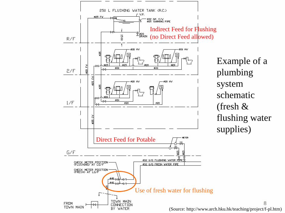
(Source: http://www.arch.hku.hk/teaching/project/f-pl.htm)
Example of a
plumbing
system
schematic
(fresh &
flushing water
supplies)
Use of fresh water for flushing
Direct Feed for Potable
Indirect Feed for Flushing
(no Direct Feed allowed)
8
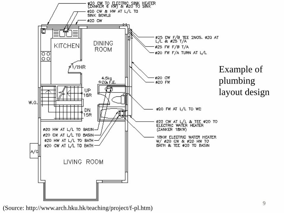
(Source: http://www.arch.hku.hk/teaching/project/f-pl.htm)
Example of
plumbing
layout design
9

Design principles
• Plumbing proposal (cont’d)
• A schedule containing the following items :-
• (a) number of flats/units in each block of the building
• (b) address of each premise needs individually metered water
supply
• (c) number of draw-off points and sanitary fittings in each unit
• (d) estimated daily consumption for all trade purposes
• Meters arranged in meter rooms & fittings at the meter
positions
• The relevant standards for the pipe materials to be used
• Capacities of the water storage tanks e.g. roof storage tanks
10
Water demand
• Water demand depends on:
• Type of building & its function
• Number of occupants, permanent or transitional
• Requirement for fire protection systems
• Landscape & water features
• Typical appliances using the cold water
• WC cistern, wash basin, bath, shower, sink
• Washing machine, dishwasher
• Urinal flushing cistern
11
Water demand
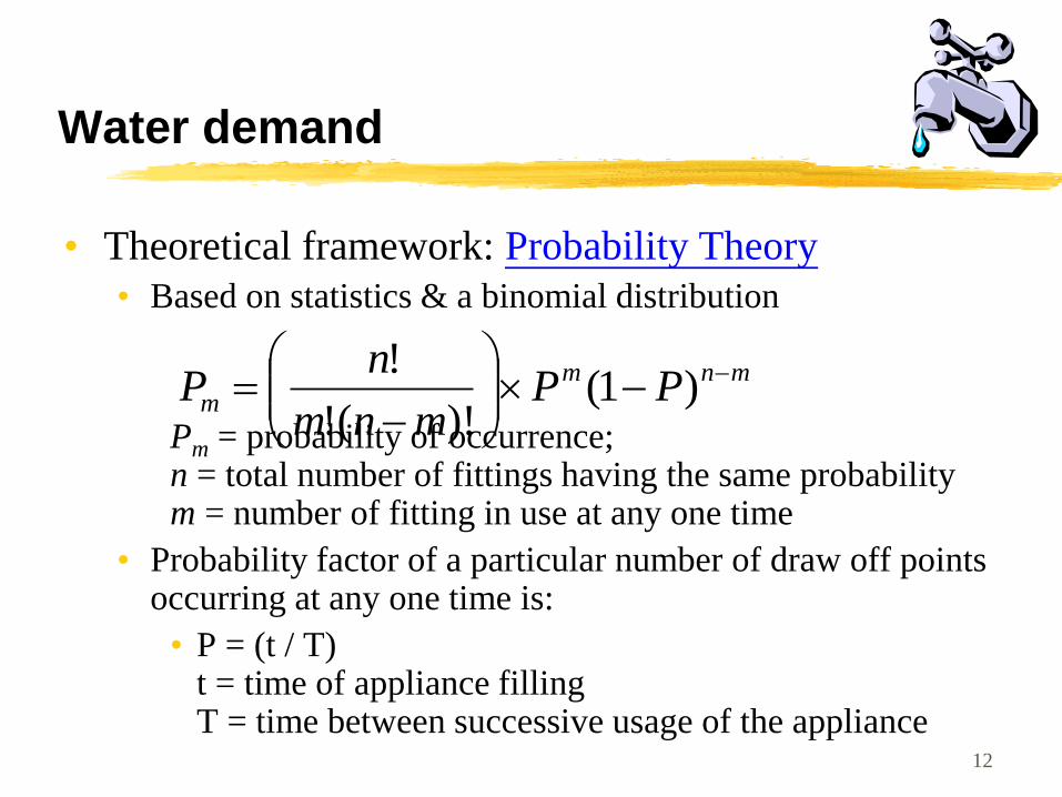
• Theoretical framework: Probability Theory
• Based on statistics & a binomial distribution
Pm = probability of occurrence; n = total number of fittings having the same probability m = number of fitting in use at any one time
• Probability factor of a particular number of draw off points occurring at any one time is:
• P = (t / T) t = time of appliance filling T = time between successive usage of the appliance
mnm
m PPmnm
nP
)1(
)!(!
!
12
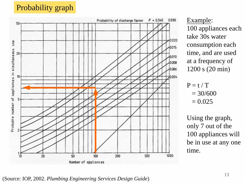
(Source: IOP, 2002. Plumbing Engineering Services Design Guide)
Probability graph
Example:
100 appliances each
take 30s water
consumption each
time, and are used
at a frequency of
1200 s (20 min)
P = t / T
= 30/600
= 0.025
Using the graph,
only 7 out of the
100 appliances will
be in use at any one
time.
13
Water demand
• Simultaneous demand
• Most fittings are used only at irregular intervals
• It is unlikely that all the appliances will be used
simultaneously
• No need to size pipework on continuous maximum
• Key factors to consider:
• Capacity of appliance (L)
• Draw-off flow rate (L/s)
• Draw-off period, or time taken to fill appliance (sec)
• Frequency of use, time between each use (sec)
14
Water demand
• Loading Unit (L.U.)
• A factor given to an appliance relating the flow rate at its
terminal fitting to
• Length of time in use
• Frequency of use for a particular type
• Use of building
• Evaluate the ‘probable maximum’
• Relates the flow rate to the probable usage
• Also, consider design & minimum flow rates
15
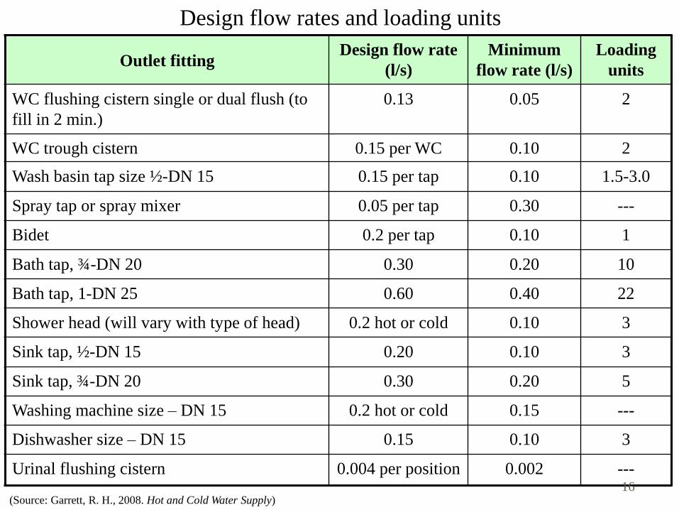
Design flow rates and loading units
Outlet fitting Design flow rate
(l/s)
Minimum
flow rate (l/s)
Loading
units
WC flushing cistern single or dual flush (to
fill in 2 min.)
0.13 0.05 2
WC trough cistern 0.15 per WC 0.10 2
Wash basin tap size ½ -DN 15 0.15 per tap 0.10 1.5-3.0
Spray tap or spray mixer 0.05 per tap 0.30 ---
Bidet 0.2 per tap 0.10 1
Bath tap, ¾ -DN 20 0.30 0.20 10
Bath tap, 1-DN 25 0.60 0.40 22
Shower head (will vary with type of head) 0.2 hot or cold 0.10 3
Sink tap, ½ -DN 15 0.20 0.10 3
Sink tap, ¾ -DN 20 0.30 0.20 5
Washing machine size – DN 15 0.2 hot or cold 0.15 ---
Dishwasher size – DN 15 0.15 0.10 3
Urinal flushing cistern 0.004 per position 0.002 ---
(Source: Garrett, R. H., 2008. Hot and Cold Water Supply) 16

Water demand
• Apply probability theory, with caution
• Assume random usage with fittings (is this true?)
• Determine max. frequencies of use
• Estimate average water usage rates & time
• The theory is valid with large nos. of fittings
• Often expect to be exceeded at 1% time only (99%
confidence level)
• Reliability and risk management (what is the consequence)
• Need to understand the context/circumstance
• Is it similar to average/typical? (* adjust data if needed)
• Any foreseeable special requirements? 17
Water demand
• Design flow considerations
• A small increase in demand over design level will cause a
slight reduction in pressure/flow (unlikely to be noticed by
users)
• Exceptional cases, such as:
• Cleaners’ sinks (depends on one’s behavior)
• Urinal flushing cisterns (continuous small flow)
• Team changing rooms at sport clubs (high demand)
• Special events (ad hoc demand)
18

19
Relationship between Loading Unit
and the respective flow rate (L/s)
e.g.
100L.U. equivalent to 1.3L/s
1000L.U. = 7 L/s (not 13L/s)
(Source: Plumbing Engineering Services Design Guide)
Water storage
• Purposes of water storage
• Provide for an interruption of supply
• Accommodate peak demand
• Provide a pressure (head) for gravity supplies
• Design factors
• Type and number of fittings
• Frequency and pattern of use
• Likelihood and frequency of breakdown of supply (often
design for 12- or 24-hour reserve capacity)
• Water storage requirements in Hong Kong to follow WSD
recommendations 20
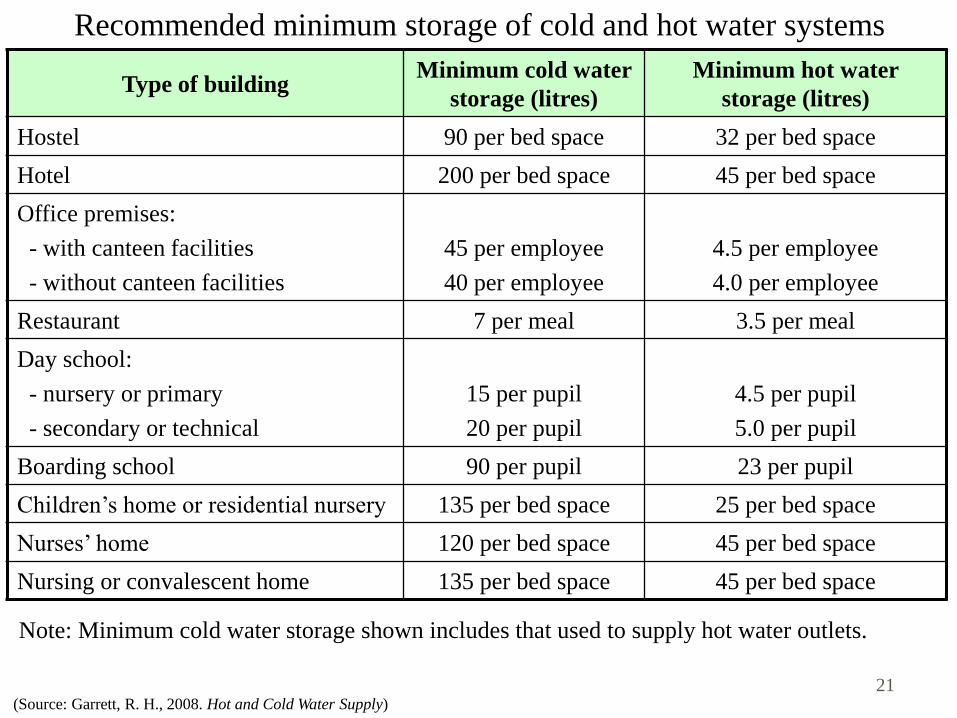
Recommended minimum storage of cold and hot water systems
Type of building Minimum cold water
storage (litres)
Minimum hot water
storage (litres)
Hostel 90 per bed space 32 per bed space
Hotel 200 per bed space 45 per bed space
Office premises:
- with canteen facilities
- without canteen facilities
45 per employee
40 per employee
4.5 per employee
4.0 per employee
Restaurant 7 per meal 3.5 per meal
Day school:
- nursery or primary
- secondary or technical
15 per pupil
20 per pupil
4.5 per pupil
5.0 per pupil
Boarding school 90 per pupil 23 per pupil
Children’s home or residential nursery 135 per bed space 25 per bed space
Nurses’ home 120 per bed space 45 per bed space
Nursing or convalescent home 135 per bed space 45 per bed space
(Source: Garrett, R. H., 2008. Hot and Cold Water Supply)
Note: Minimum cold water storage shown includes that used to supply hot water outlets.
21
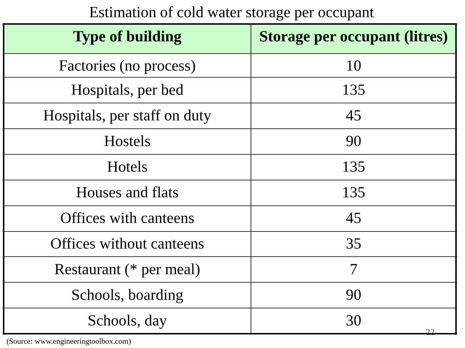
Estimation of cold water storage per occupant
Type of building Storage per occupant (litres)
Factories (no process) 10
Hospitals, per bed 135
Hospitals, per staff on duty 45
Hostels 90
Hotels 135
Houses and flats 135
Offices with canteens 45
Offices without canteens 35
Restaurant (* per meal) 7
Schools, boarding 90
Schools, day 30
(Source: www.engineeringtoolbox.com) 22
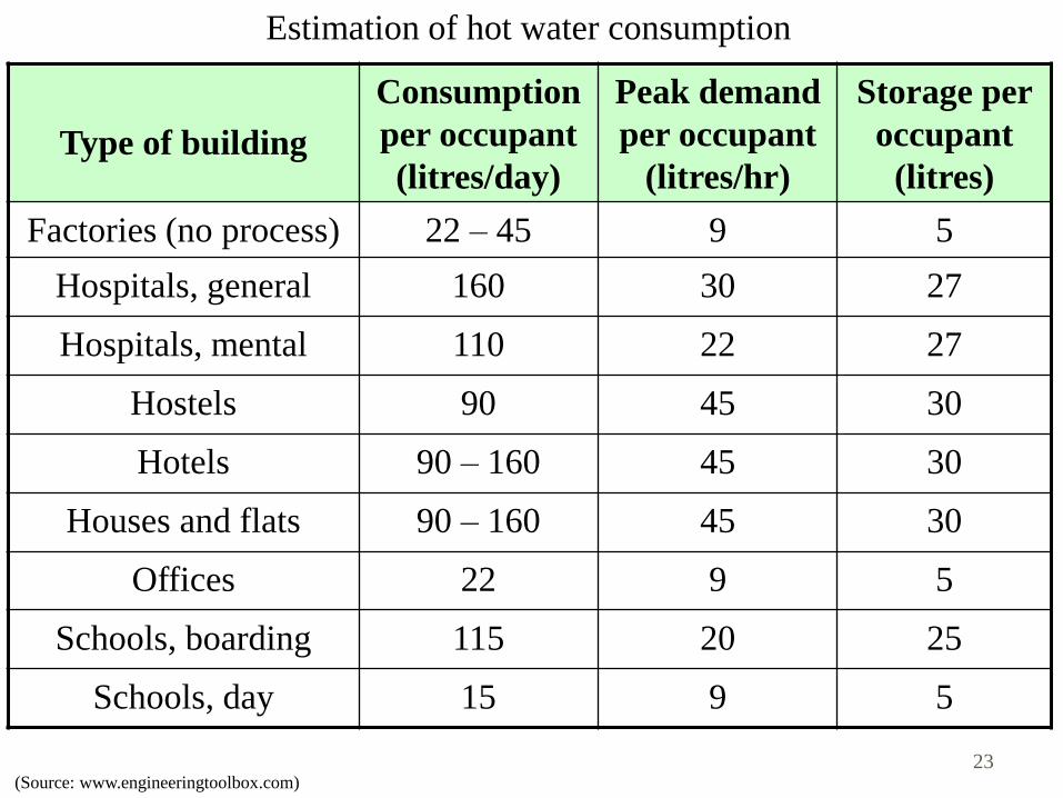
Estimation of hot water consumption
Type of building
Consumption
per occupant
(litres/day)
Peak demand
per occupant
(litres/hr)
Storage per
occupant
(litres)
Factories (no process) 22 – 45 9 5
Hospitals, general 160 30 27
Hospitals, mental 110 22 27
Hostels 90 45 30
Hotels 90 – 160 45 30
Houses and flats 90 – 160 45 30
Offices 22 9 5
Schools, boarding 115 20 25
Schools, day 15 9 5
(Source: www.engineeringtoolbox.com) 23
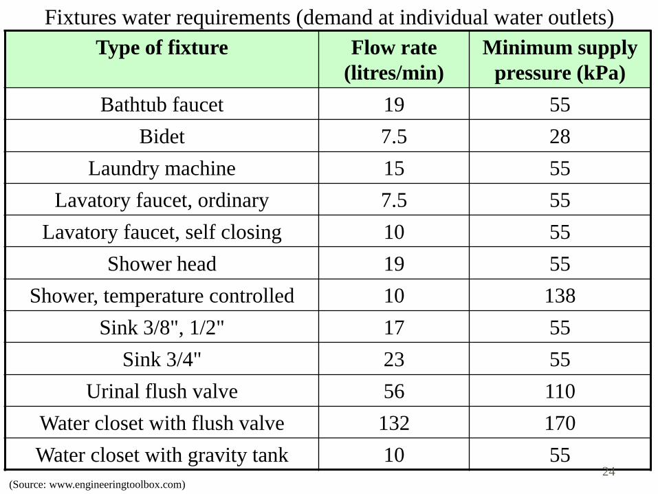
Fixtures water requirements (demand at individual water outlets)
Type of fixture Flow rate
(litres/min)
Minimum supply
pressure (kPa)
Bathtub faucet 19 55
Bidet 7.5 28
Laundry machine 15 55
Lavatory faucet, ordinary 7.5 55
Lavatory faucet, self closing 10 55
Shower head 19 55
Shower, temperature controlled 10 138
Sink 3/8", 1/2" 17 55
Sink 3/4" 23 55
Urinal flush valve 56 110
Water closet with flush valve 132 170
Water closet with gravity tank 10 55
(Source: www.engineeringtoolbox.com) 24
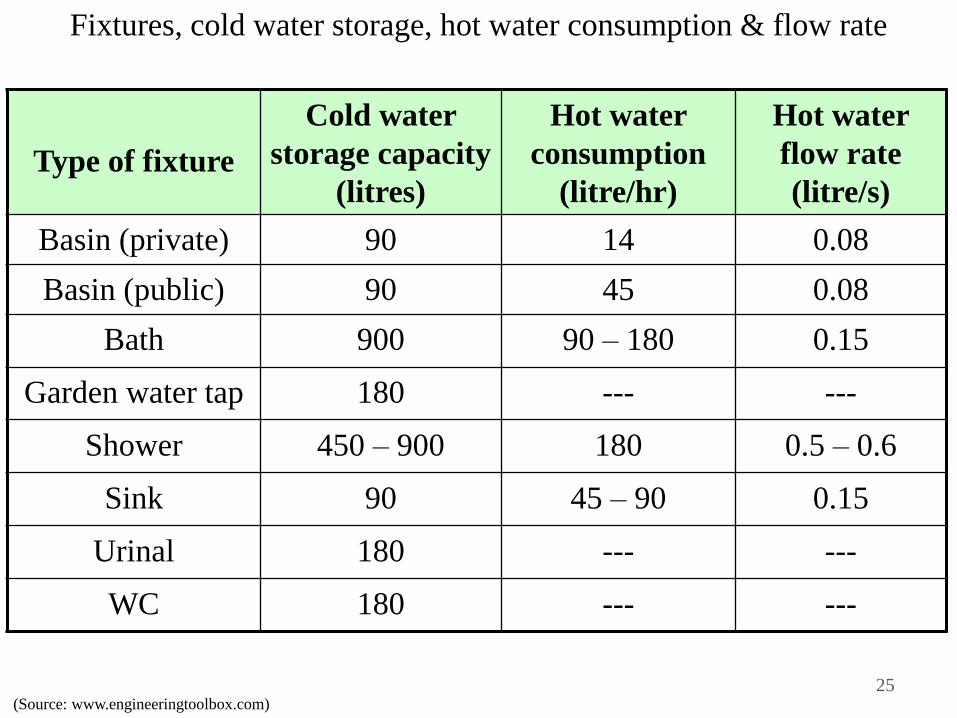
Fixtures, cold water storage, hot water consumption & flow rate
Type of fixture
Cold water
storage capacity
(litres)
Hot water
consumption
(litre/hr)
Hot water
flow rate
(litre/s)
Basin (private) 90 14 0.08
Basin (public) 90 45 0.08
Bath 900 90 – 180 0.15
Garden water tap 180 --- ---
Shower 450 – 900 180 0.5 – 0.6
Sink 90 45 – 90 0.15
Urinal 180 --- ---
WC 180 --- ---
(Source: www.engineeringtoolbox.com) 25
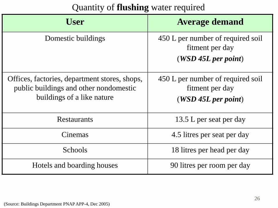
Quantity of flushing water required
User Average demand
Domestic buildings 450 L per number of required soil
fitment per day
(WSD 45L per point)
Offices, factories, department stores, shops,
public buildings and other nondomestic
buildings of a like nature
450 L per number of required soil
fitment per day
(WSD 45L per point)
Restaurants 13.5 L per seat per day
Cinemas 4.5 litres per seat per day
Schools 18 litres per head per day
Hotels and boarding houses 90 litres per room per day
(Source: Buildings Department PNAP APP-4, Dec 2005) 26
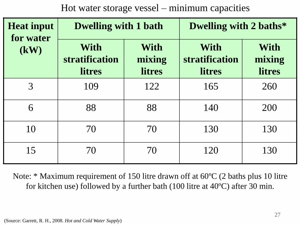
(Source: Garrett, R. H., 2008. Hot and Cold Water Supply)
Heat input
for water
(kW)
Dwelling with 1 bath Dwelling with 2 baths*
With
stratification
litres
With
mixing
litres
With
stratification
litres
With
mixing
litres
3 109 122 165 260
6 88 88 140 200
10 70 70 130 130
15 70 70 120 130
Hot water storage vessel – minimum capacities
Note: * Maximum requirement of 150 litre drawn off at 60ºC (2 baths plus 10 litre
for kitchen use) followed by a further bath (100 litre at 40ºC) after 30 min.
27
System Arrangements
• Direct Supply
• Indirect Supply
• sump and pump supply system
• cascade sump and pump supply system
• pneumatic booster supply system
• variable speed pumping supply system
• top floor boosting supply system
• gravity supply system
• Note that the overall system may include one or more
of the above system arrangements
28
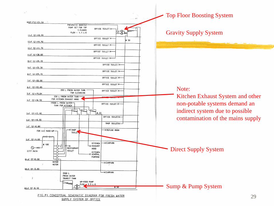
29
Top Floor Boosting System
Gravity Supply System
Sump & Pump System
Direct Supply System
Note:
Kitchen Exhaust System and other
non-potable systems demand an
indirect system due to possible
contamination of the mains supply
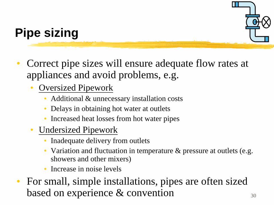
Pipe sizing
• Correct pipe sizes will ensure adequate flow rates at appliances and avoid problems, e.g.
• Oversized Pipework
• Additional & unnecessary installation costs
• Delays in obtaining hot water at outlets
• Increased heat losses from hot water pipes
• Undersized Pipework
• Inadequate delivery from outlets
• Variation and fluctuation in temperature & pressure at outlets (e.g. showers and other mixers)
• Increase in noise levels
• For small, simple installations, pipes are often sized based on experience & convention 30
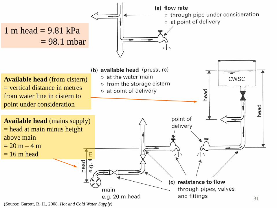
(Source: Garrett, R. H., 2008. Hot and Cold Water Supply)
Available head (from cistern)
= vertical distance in metres
from water line in cistern to
point under consideration
Available head (mains supply)
= head at main minus height
above main
= 20 m – 4 m
= 16 m head
1 m head = 9.81 kPa
= 98.1 mbar
31
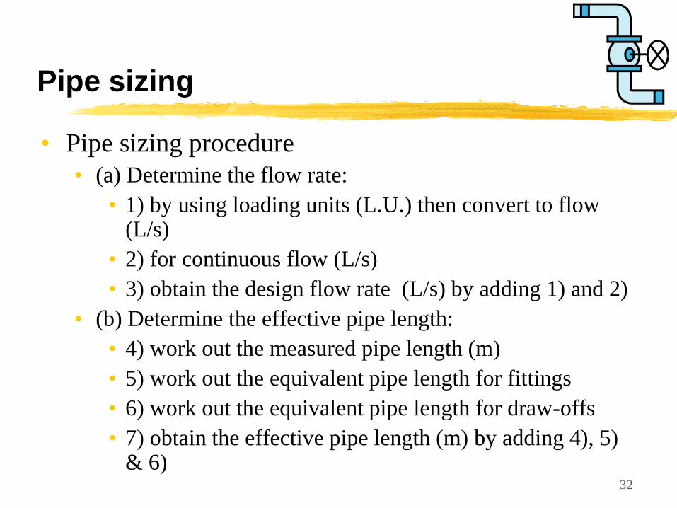
Pipe sizing
• Pipe sizing procedure
• (a) Determine the flow rate:
• 1) by using loading units (L.U.) then convert to flow (L/s)
• 2) for continuous flow (L/s)
• 3) obtain the design flow rate (L/s) by adding 1) and 2)
• (b) Determine the effective pipe length:
• 4) work out the measured pipe length (m)
• 5) work out the equivalent pipe length for fittings
• 6) work out the equivalent pipe length for draw-offs
• 7) obtain the effective pipe length (m) by adding 4), 5) & 6)
32
Pipe sizing
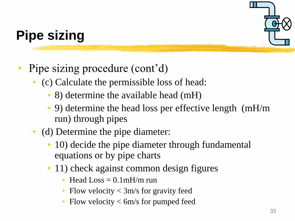
• Pipe sizing procedure (cont’d)
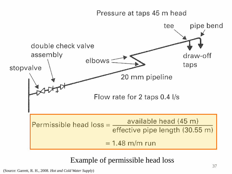
• (c) Calculate the permissible loss of head:
• 8) determine the available head (mH)
• 9) determine the head loss per effective length (mH/m run) through pipes
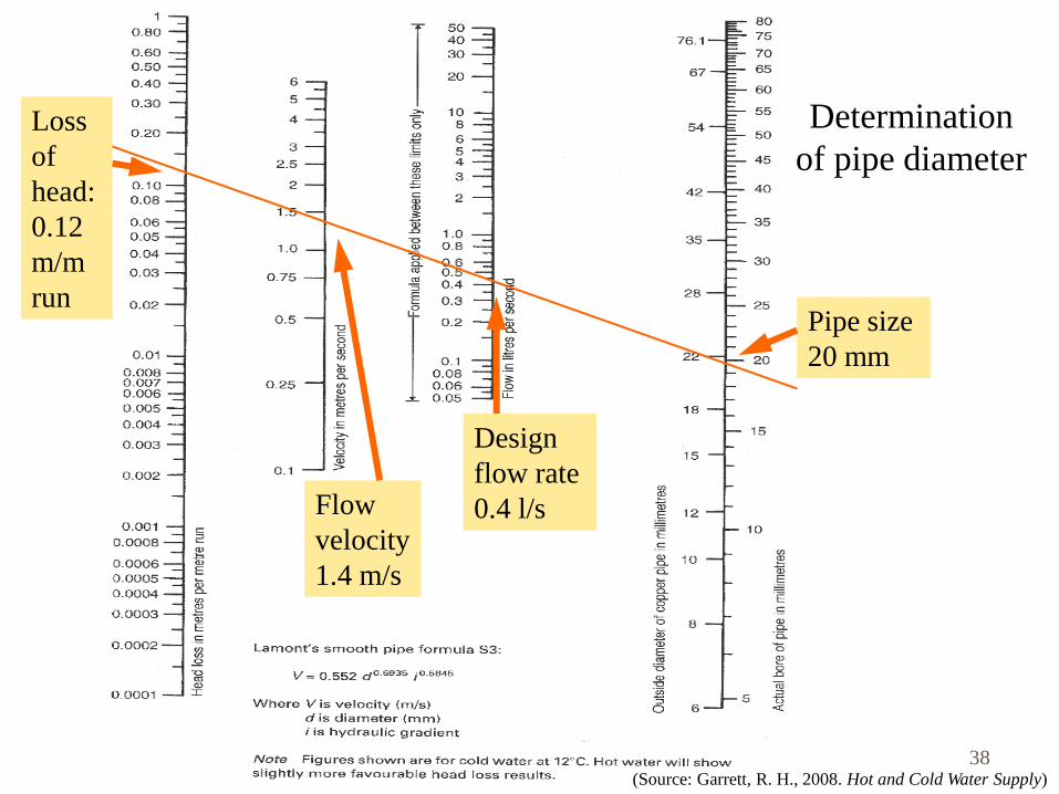
• (d) Determine the pipe diameter:
• 10) decide the pipe diameter through fundamental equations or by pipe charts
• 11) check against common design figures
• Head Loss = 0.1mH/m run
• Flow velocity < 3m/s for gravity feed
• Flow velocity < 6m/s for pumped feed 33
(Source: Garrett, R. H., 2008. Hot and Cold Water Supply)
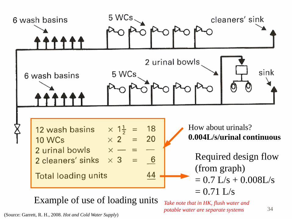
Example of use of loading units
Required design flow
(from graph)
= 0.7 L/s + 0.008L/s
= 0.71 L/s
How about urinals?
0.004L/s/urinal continuous
34 Take note that in HK, flush water and
potable water are separate systems
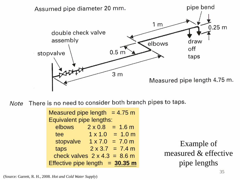
(Source: Garrett, R. H., 2008. Hot and Cold Water Supply)
Example of
measured & effective
pipe lengths
Measured pipe length = 4.75 m
Equivalent pipe lengths:
elbows 2 x 0.8 = 1.6 m
tee 1 x 1.0 = 1.0 m
stopvalve 1 x 7.0 = 7.0 m
taps 2 x 3.7 = 7.4 m
check valves 2 x 4.3 = 8.6 m
Effective pipe length = 30.35 m
35
(Source: Garrett, R. H., 2008. Hot and Cold Water Supply)
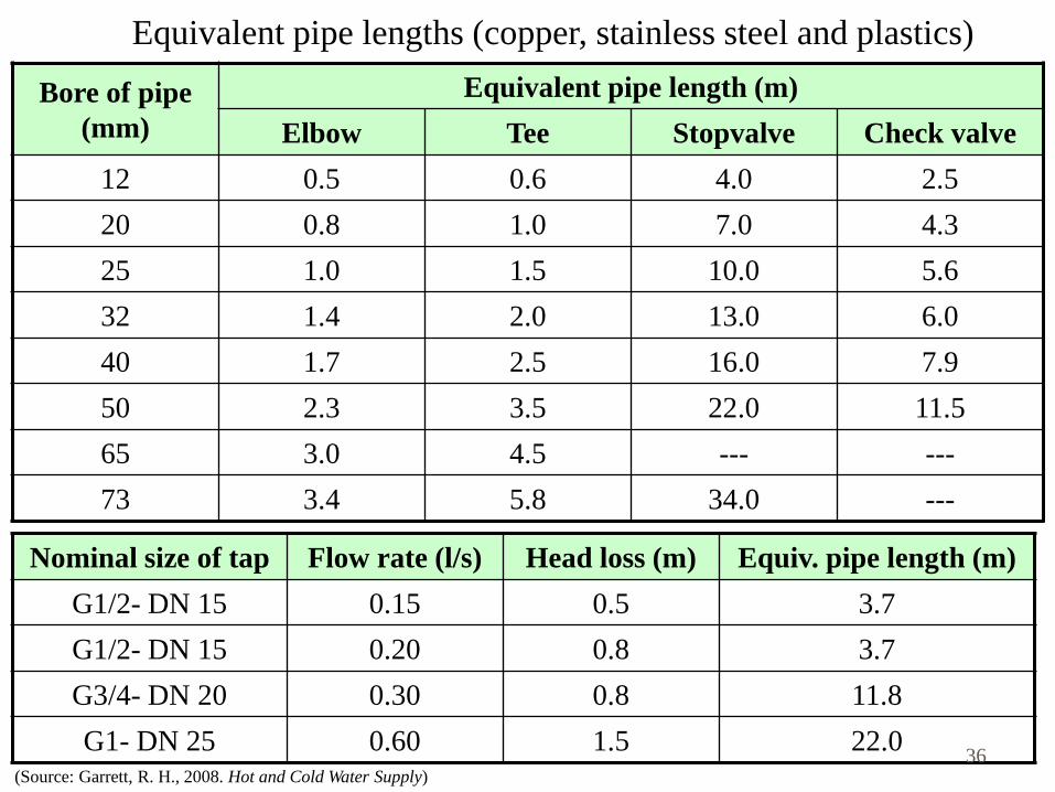
Equivalent pipe lengths (copper, stainless steel and plastics)
Bore of pipe
(mm)
Equivalent pipe length (m)
Elbow Tee Stopvalve Check valve
12 0.5 0.6 4.0 2.5
20 0.8 1.0 7.0 4.3
25 1.0 1.5 10.0 5.6
32 1.4 2.0 13.0 6.0
40 1.7 2.5 16.0 7.9
50 2.3 3.5 22.0 11.5
65 3.0 4.5 --- ---
73 3.4 5.8 34.0 ---
Nominal size of tap Flow rate (l/s) Head loss (m) Equiv. pipe length (m)
G1/2- DN 15 0.15 0.5 3.7
G1/2- DN 15 0.20 0.8 3.7
G3/4- DN 20 0.30 0.8 11.8
G1- DN 25 0.60 1.5 22.0 36
(Source: Garrett, R. H., 2008. Hot and Cold Water Supply)
Example of permissible head loss 37
(Source: Garrett, R. H., 2008. Hot and Cold Water Supply)
Determination
of pipe diameter
Pipe size
20 mm
Design
flow rate
0.4 l/s
Loss
of
head:
0.12
m/m
run
Flow
velocity
1.4 m/s
38
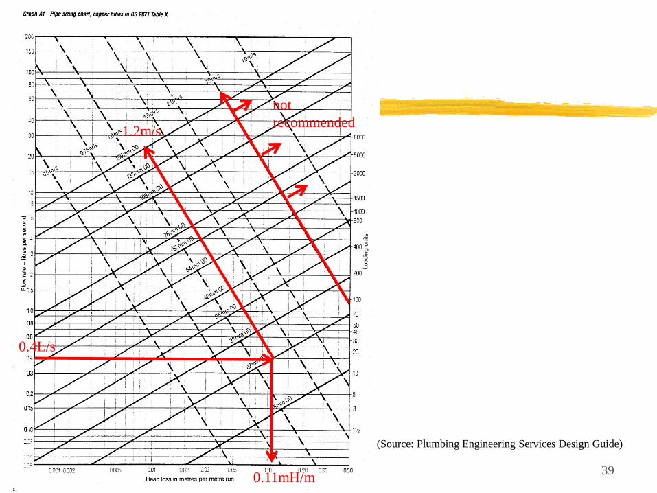
39
(Source: Plumbing Engineering Services Design Guide)
not
recommended
0.11mH/m
0.4L/s
1.2m/s
(Source: Garrett, R. H., 2008. Hot and Cold Water Supply)
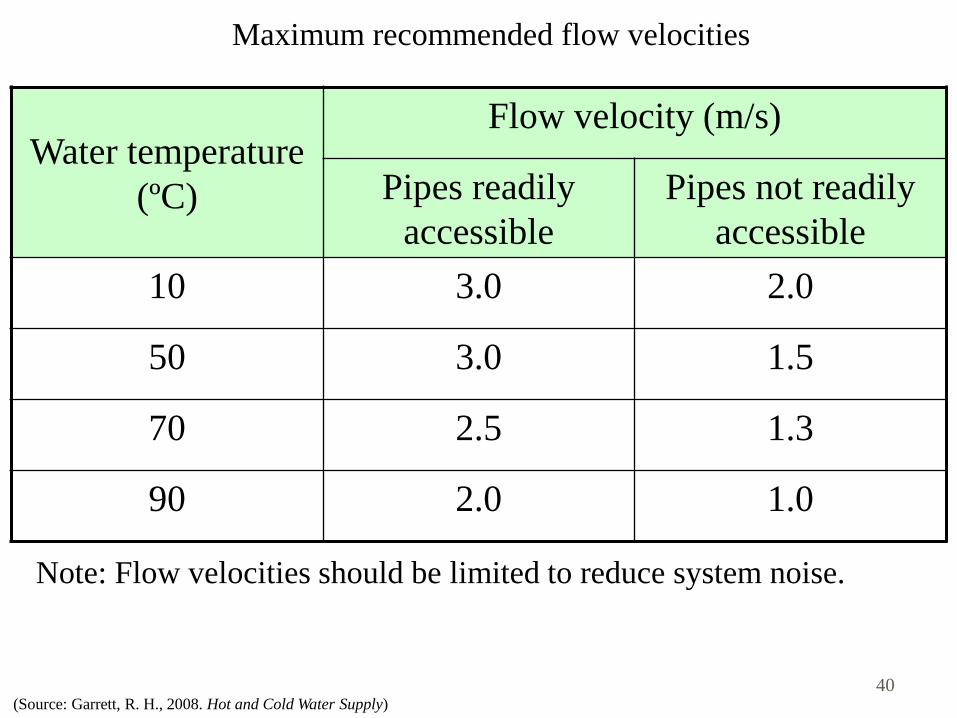
Maximum recommended flow velocities
Water temperature
(ºC)
Flow velocity (m/s)
Pipes readily
accessible
Pipes not readily
accessible
10 3.0 2.0
50 3.0 1.5
70 2.5 1.3
90 2.0 1.0
Note: Flow velocities should be limited to reduce system noise.
40
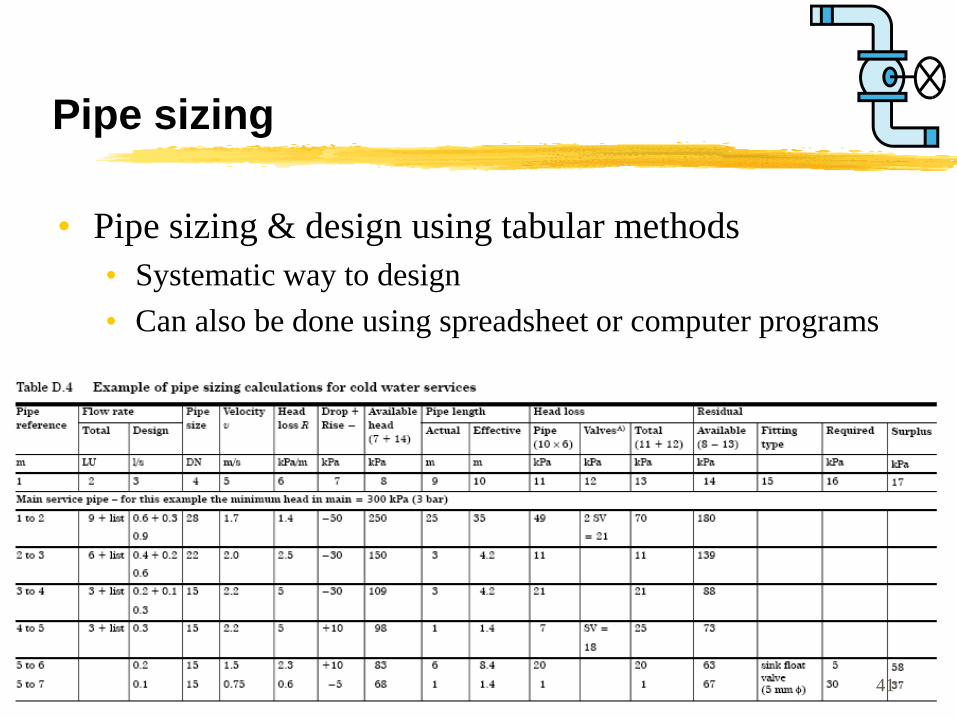
Pipe sizing
• Pipe sizing & design using tabular methods
• Systematic way to design
• Can also be done using spreadsheet or computer programs
41
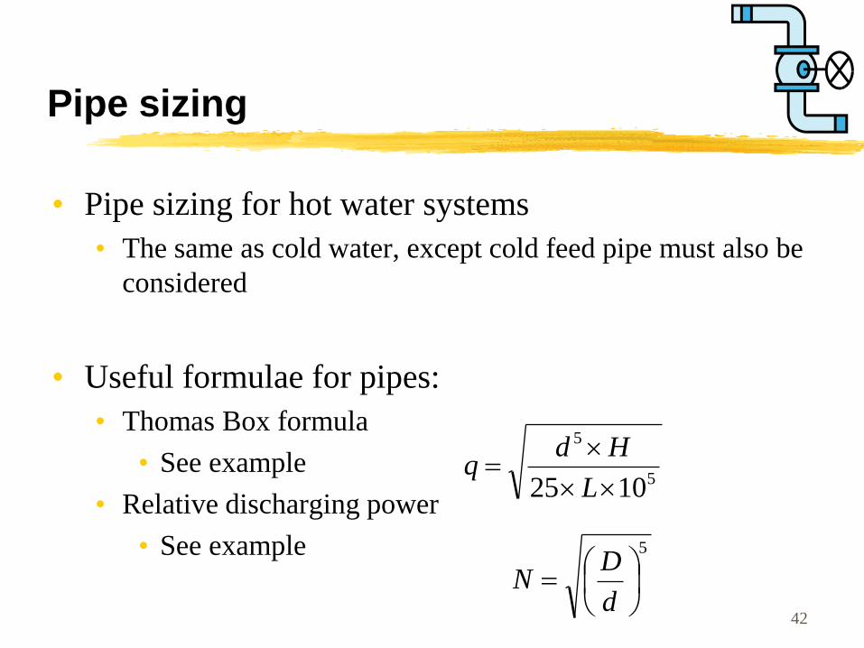
Pipe sizing
• Pipe sizing for hot water systems
• The same as cold water, except cold feed pipe must also be
considered
• Useful formulae for pipes:
• Thomas Box formula
• See example
• Relative discharging power
• See example 5
d
DN
5
5
1025
L
Hdq
42
(Source: Hall, F. and Greeno, R., 2008. Building Services Handbook)
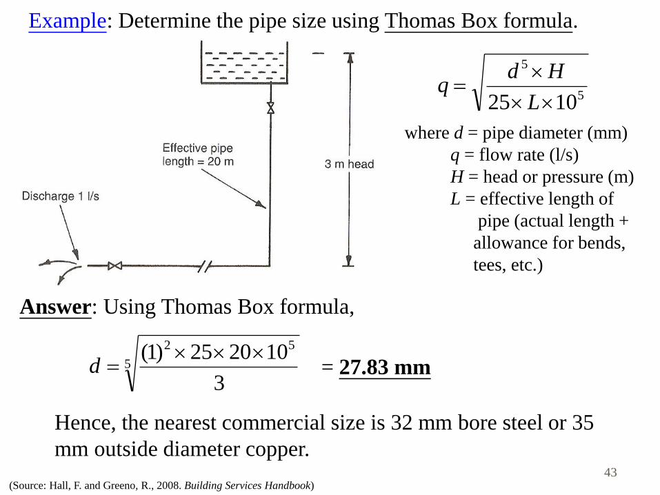
Example: Determine the pipe size using Thomas Box formula.
5
5
1025
L
Hdq
where d = pipe diameter (mm)
q = flow rate (l/s)
H = head or pressure (m)
L = effective length of
pipe (actual length +
allowance for bends,
tees, etc.)
Answer: Using Thomas Box formula,
5
52
3
102025)1( d = 27.83 mm
Hence, the nearest commercial size is 32 mm bore steel or 35
mm outside diameter copper. 43
(Source: Hall, F. and Greeno, R., 2008. Building Services Handbook)
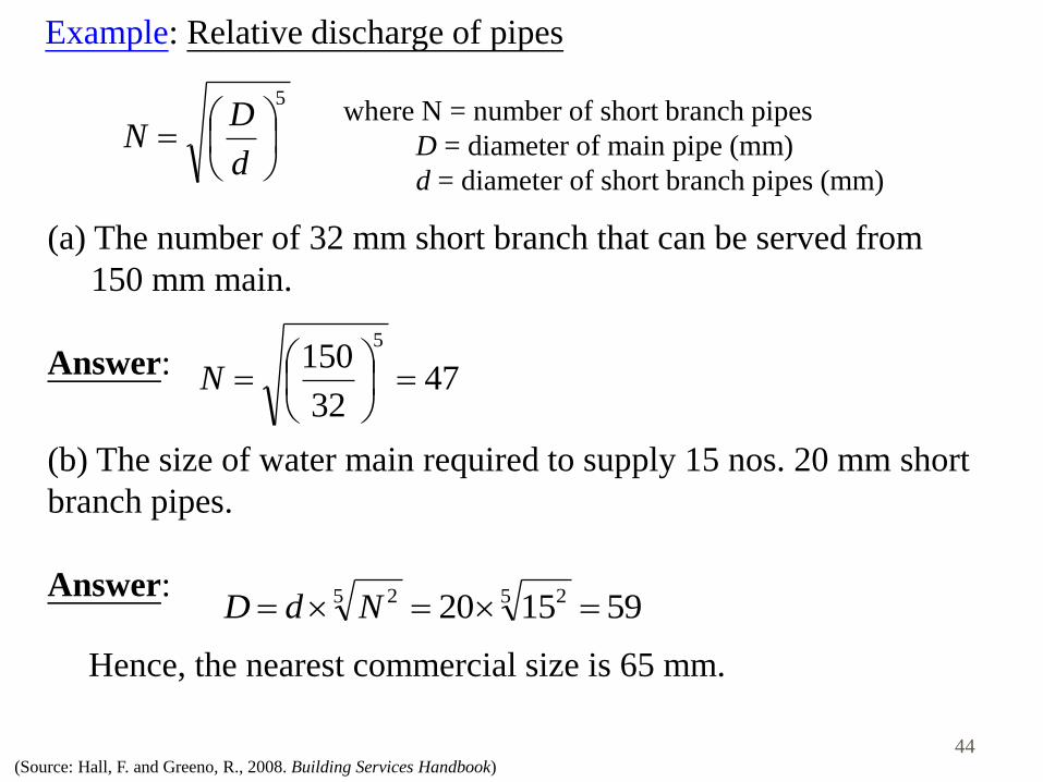
Example: Relative discharge of pipes
where N = number of short branch pipes
D = diameter of main pipe (mm)
d = diameter of short branch pipes (mm)
(a) The number of 32 mm short branch that can be served from
150 mm main.
Answer:
Hence, the nearest commercial size is 65 mm.
5
d
DN
4732
1505
N
(b) The size of water main required to supply 15 nos. 20 mm short
branch pipes.
Answer:
591520 5 25 2 NdD
44
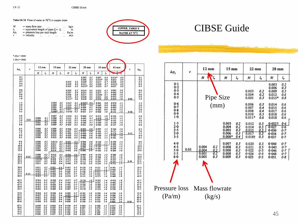
45
CIBSE Guide
Mass flowrate
(kg/s)
Pressure loss
(Pa/m)
Pipe Size
(mm)

Copper (W/m run) at 40oC above ambient
Nominal Bore Bare Insulated
13 28 8
19 39 11
25 48 13
32 58 16
38 68 17
51 88 20
63 106 24
76 120 26
102 160 35
127 190 42
152 220 47
Hot Water System
Secondary Return Pipe Sizing
• Heat loss from hot water pipe
• Supply pipe sizing same as
cold water supply
• Consider supply temp = 65oC
• Return temp = 55oC (min.)
• Take supply pipe = 60% of
heat loss (i.e. drop of temp = 6oC)
• Use Q = mcT, then mass flow of water is found
• Return pipe is sized accordingly
46

Worked Example
• Consider supply pipe size = 38mm (17W/m heat loss)
• Assume supply pipe length = 40m 680W heat loss
• If temperature drop = 6oC (from 65oC – 59oC at end of supply)
• Q=mcT, thus 680 = m x 4200 x 6, thus m = 0.026kg/s
• Use smallest 12mm Cu pipe
• 0.026 kg/s 130Pa/m run (0.013mH/m run) (acceptable)
• Heat loss = 8 W/m x 40m = 320W
• Q = mcT, thus 320 = 0.026 x 4200 x T, T = 3oC (in return)
• Thus return temp = 56oC (acceptable)
47
Pipe materials
• Design & selection factors:
• Effect on water quality
• Cost, service life and maintenance needs
• For metallic pipes, internal and external corrosion
• Compatibility of materials
• Ageing, fatigue and temperature effects, especially in plastics
• Mechanical properties and durability
• Vibration, stress or settlement
• Internal water pressure
48
Pipe materials
• Commonly used pipe materials, such as:
• Copper (BS EN 1057)
• Galvanised iron (GI) with PVC-C lining (BS 1387)
• PVC, unplasticized PVC, PB, PE, PE-X
• Stainless steel (BS 4127)
• Ductile iron (BS EN 545) (for pipe dia. > 80 mm)
• Mild steel (for pipe dia. > 600 mm)
• * Plastic material generally will degrade on
prolonged exposure to ultra-voilet light
49
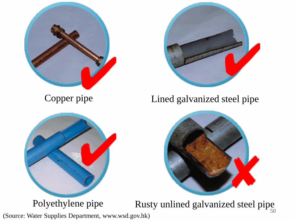
(Source: Water Supplies Department, www.wsd.gov.hk)
Copper pipe
Polyethylene pipe
Lined galvanized steel pipe
Rusty unlined galvanized steel pipe 50
(Source: Water Supplies Department, www.wsd.gov.hk)
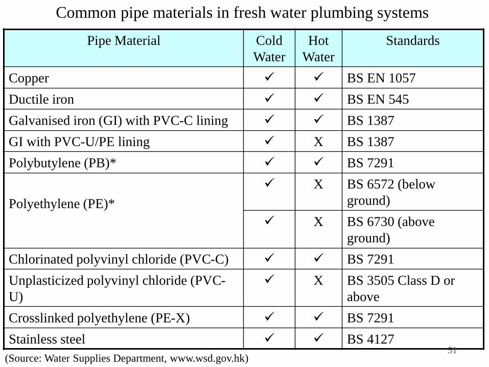
Pipe Material Cold
Water
Hot
Water
Standards
Copper BS EN 1057
Ductile iron BS EN 545
Galvanised iron (GI) with PVC-C lining BS 1387
GI with PVC-U/PE lining X BS 1387
Polybutylene (PB)* BS 7291
Polyethylene (PE)*
X BS 6572 (below
ground)
X BS 6730 (above
ground)
Chlorinated polyvinyl chloride (PVC-C) BS 7291
Unplasticized polyvinyl chloride (PVC-
U)
X BS 3505 Class D or
above
Crosslinked polyethylene (PE-X) BS 7291
Stainless steel BS 4127
Common pipe materials in fresh water plumbing systems
51
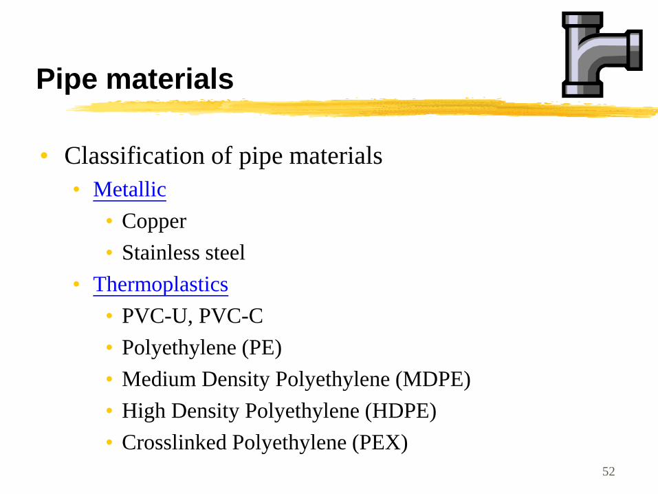
Pipe materials
• Classification of pipe materials
• Metallic
• Copper
• Stainless steel
• Thermoplastics
• PVC-U, PVC-C
• Polyethylene (PE)
• Medium Density Polyethylene (MDPE)
• High Density Polyethylene (HDPE)
• Crosslinked Polyethylene (PEX)
52
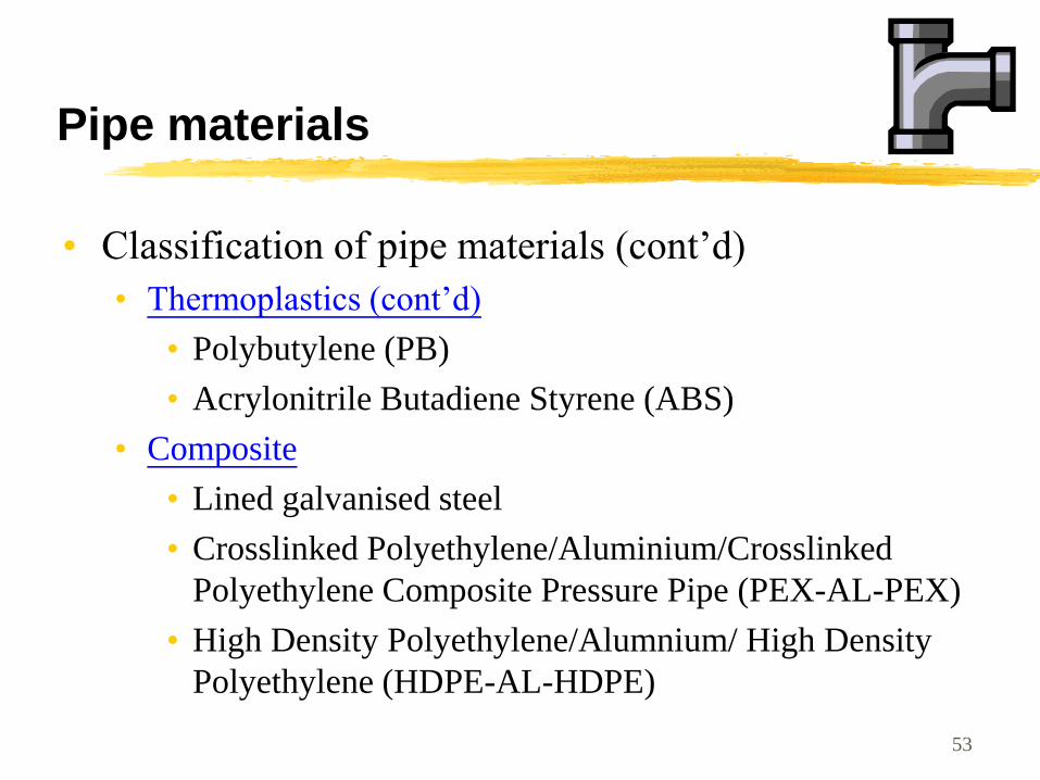
Pipe materials
• Classification of pipe materials (cont’d)
• Thermoplastics (cont’d)
• Polybutylene (PB)
• Acrylonitrile Butadiene Styrene (ABS)
• Composite
• Lined galvanised steel
• Crosslinked Polyethylene/Aluminium/Crosslinked
Polyethylene Composite Pressure Pipe (PEX-AL-PEX)
• High Density Polyethylene/Alumnium/ High Density
Polyethylene (HDPE-AL-HDPE)
53
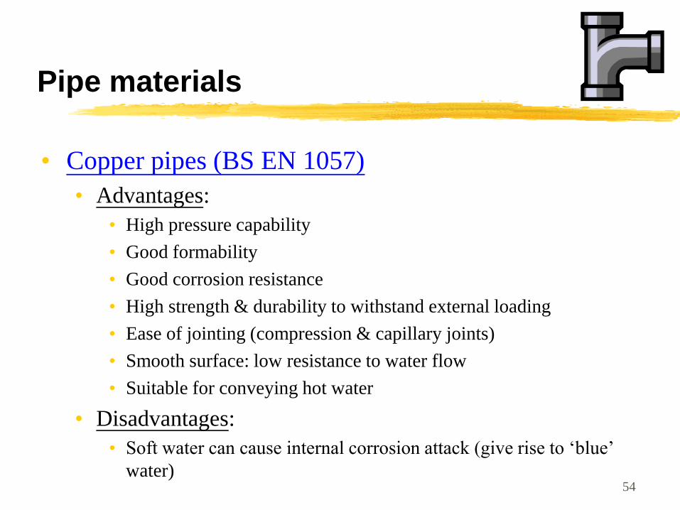
Pipe materials
• Copper pipes (BS EN 1057)
• Advantages:
• High pressure capability
• Good formability
• Good corrosion resistance
• High strength & durability to withstand external loading
• Ease of jointing (compression & capillary joints)
• Smooth surface: low resistance to water flow
• Suitable for conveying hot water
• Disadvantages:
• Soft water can cause internal corrosion attack (give rise to ‘blue’
water) 54
Pipe materials
• Stainless steel (BS 4127)
• Advantages:
• High pressure capability
• Good corrosion resistance
• High strength & durability
• Ease of jointing
• Good resistance to accidental damage
• Suitable for conveying hot water
• Disadvantage:
• More expensive than copper
55
Pipe materials
• Lined galvanised steel
• PVC-U/PVC-C/Polyethylene or epoxy resin lined
• Advantages:
• Good resistance to internal corrosion & encrustation
• Smooth surface: lower resistance to water flow
• Can be used in vulnerable conditions e.g. exposure to direct sunlight & traffic loads
• Readily compatible with existing commonly used unlined steel pipe
• Disadvantages:
• Heavy weight
• Susceptible to impact damage (great care in handling)
• Higher skills required for cutting, threading, jointing 56
Pipe materials
• PVC-U (BS 3505 Class D) • Advantages:
• Good corrosion resistance
• Light weight, low cost
• Ease of jointing
• Smooth surface: low resistance to water flow
• Not a conductor of electricity (no galvanic/oxidative corrosion)
• Disadvantages: • Brittle, susceptible to impact damage
• Long drying time of solvent cement in jointing
• Low abrasion resistance
• Permeation/degradation by certain organic contaminants
• UV degradation on prolonged exposure to sunlight
• Not suitable for hot water supply
57
Pipe materials
• PVC-C (BS 7291) • Advantages:
• Suitable for conveying hot water
• Good corrosion resistance & chemical resistance
• Light weight
• Smooth surface: low resistance to water flow
• Not a conductor of electricity (no galvanic/oxidative corrosion)
• Can be connected to other materials easily
• Disadvantages: • Brittle, susceptible to impact damage
• Long drying time of solvent cement in jointing
• Can be flammable
• Reduction in strength & rigidity with increase of temperature
• Permeation/degradation by certain organic contaminants
• Can be attacked by detergents & oxidizing agents
• UV degradation on prolonged exposure to sunlight 58
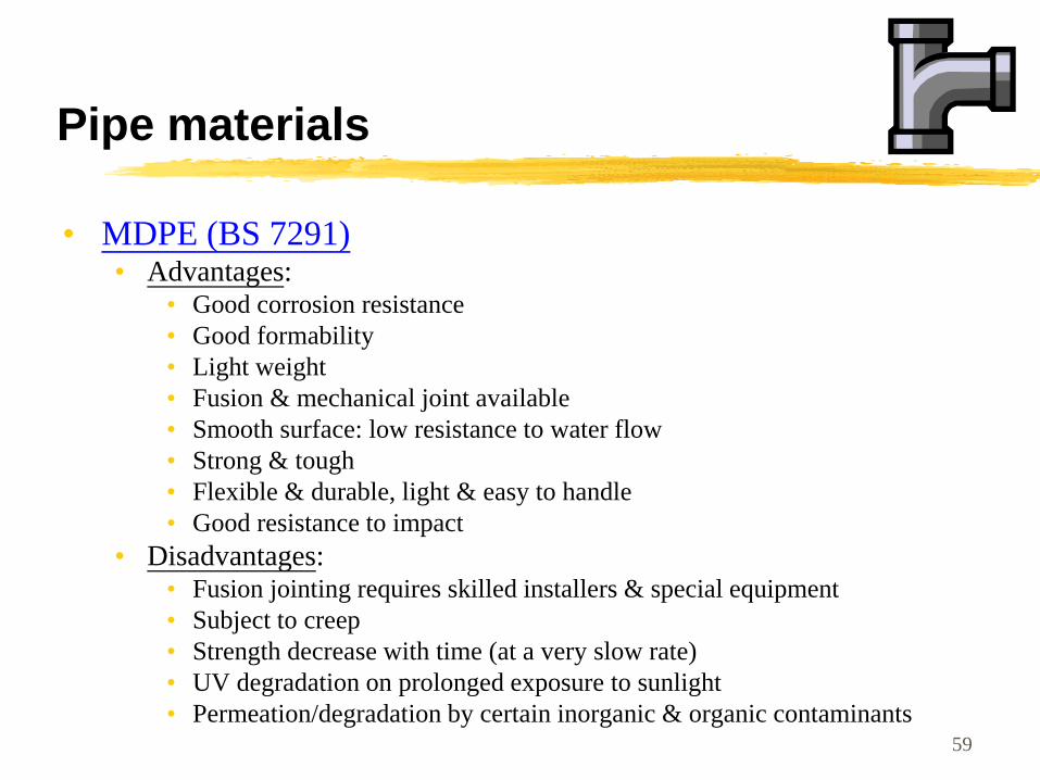
Pipe materials
• MDPE (BS 7291) • Advantages:
• Good corrosion resistance
• Good formability
• Light weight
• Fusion & mechanical joint available
• Smooth surface: low resistance to water flow
• Strong & tough
• Flexible & durable, light & easy to handle
• Good resistance to impact
• Disadvantages: • Fusion jointing requires skilled installers & special equipment
• Subject to creep
• Strength decrease with time (at a very slow rate)
• UV degradation on prolonged exposure to sunlight
• Permeation/degradation by certain inorganic & organic contaminants 59
Pipe materials
• Jointing of pipes
• Copper pipes
• Capillary solder or brazed joints
• Autogenous welding
• Compression, push, press/crimp fittings
• Steel pipes
• Screwed joints, with pipe threads
• Flange joints (screwed or welded flanges)
• Stainless steel pipes
• Compression, capillary, push, press/crimp fittings (but not joined by soft soldering)
60
Pipe materials
• Jointing of pipes (cont’d)
• Unplasticized PVC pipes
• Mechanical joints
• Compression joints
• Solvent cement welded joints
• Flange joints
• Polyethylene (PE) & polybutylene (PB) pipes
• Mechanical joints (e.g. push-fit), thermal fusion
• Acrylonitrile Butadiene Styrene (ABS) pipes
• Similar to PVC-U pipes
61
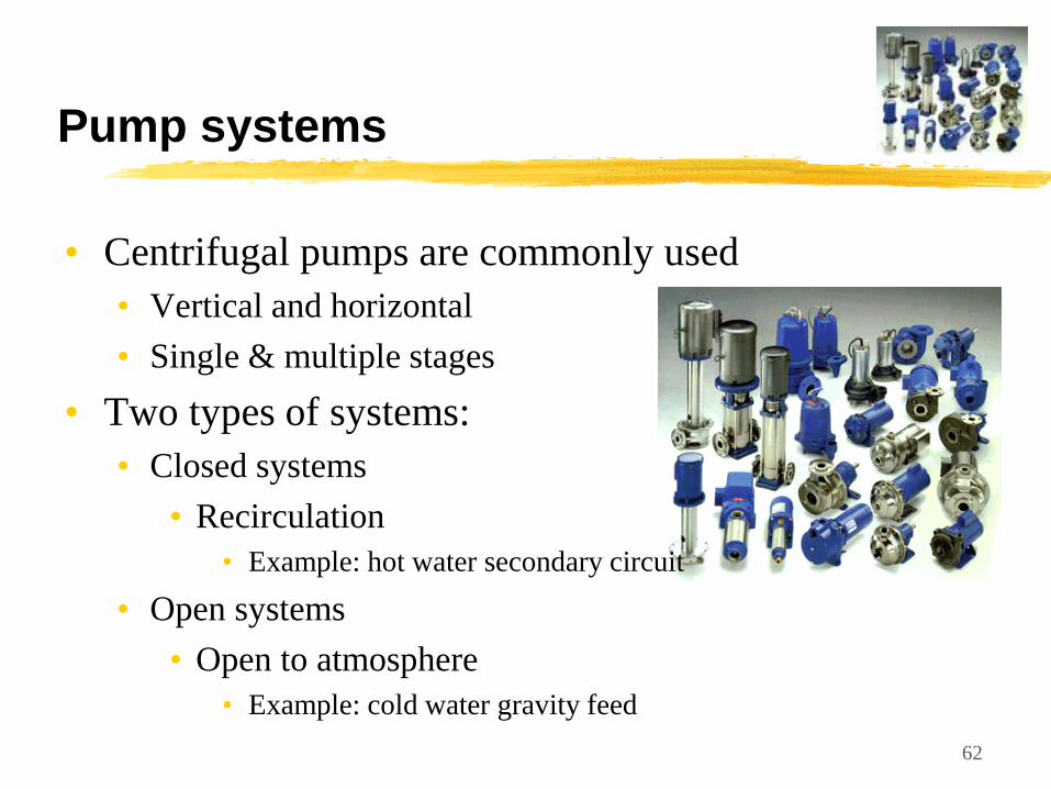
Pump systems
• Centrifugal pumps are commonly used
• Vertical and horizontal
• Single & multiple stages
• Two types of systems:
• Closed systems
• Recirculation
• Example: hot water secondary circuit
• Open systems
• Open to atmosphere
• Example: cold water gravity feed
62

Main characteristics of centrifugal & positive displacement pumps
Centrifugal pumps Positive displacement
pumps
- Capacity varies with head
- Capacity proportional to
pump speed
- Head proportional to the
square of pump speed
- Non self-priming
- Suitable for low-viscosity
liquid
- Capacity substantially
independent of head
- Capacity proportional to
speed
- Self-priming
- Suitable for various liquids
(reduced speeds usually
necessary for high viscosity
63
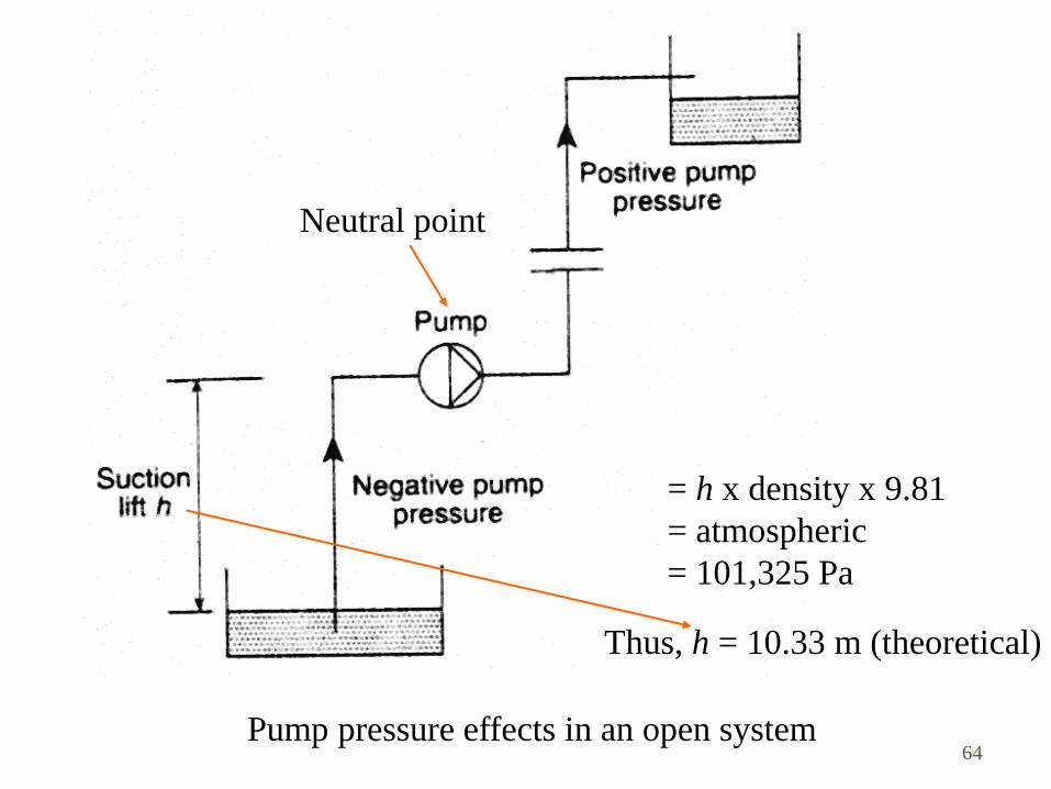
Pump pressure effects in an open system
= h x density x 9.81
= atmospheric
= 101,325 Pa
Thus, h = 10.33 m (theoretical)
Neutral point
64
Pump systems
• Pump considerations
• Practical suction lift is 5 m maximum
• Also known as net positive suction head (NPSH)
• Pump location is important for both closed and open systems
• Open system: not excessive to avoid cavitation
• Close system: Influence water level of open vent pipe & the magnitude of anti-flash margin (temp. difference between water & its saturation temp.)
• ‘Self-priming’ to evacuate air from suction line
65
Pump systems
• Pump characteristics
• Characteristics curves (e.g. from catalogue):
• Flow (m3/s, L/s)
• Total head (mH, kPa)
• Power (W, kW)
• Efficiency (%)
• No-flow conditions (flow = zero)
• Close valve pressure
• Need to prevent over-heat as pump power is continuously added to the fluid
• Pump power (W) = flow (m3/s) x pressure (Pa)
66
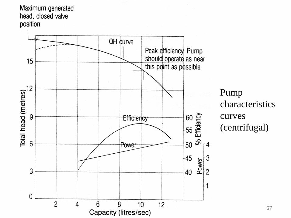
Pump
characteristics
curves
(centrifugal)
67
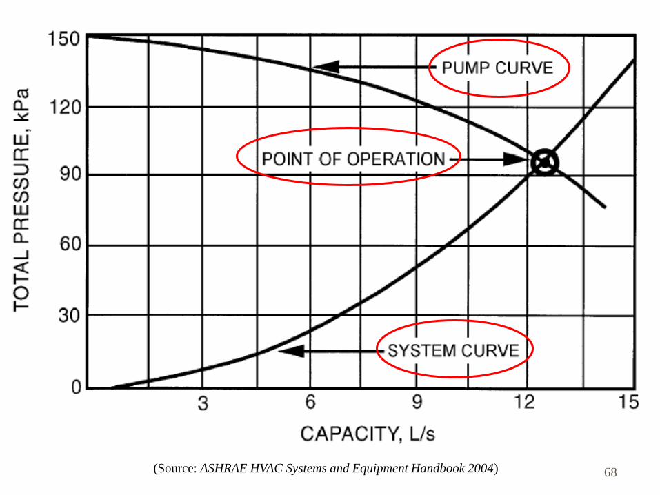
(Source: ASHRAE HVAC Systems and Equipment Handbook 2004) 68
• Pump Curve
• A characteristics of the pump alone (with particular
impeller size and configuration)
• At a certain flow rate, the pump delivers a certain pressure
• System Curve
• A characteristics of the piping network (without the pump)
relating the flowrate and the head loss
• Usually in the form P = h + kQ2
• Point of Operation
• Intersecting point between pump curve and system curve
• At the same flow, the pump pressure just compensates the
system head loss
69
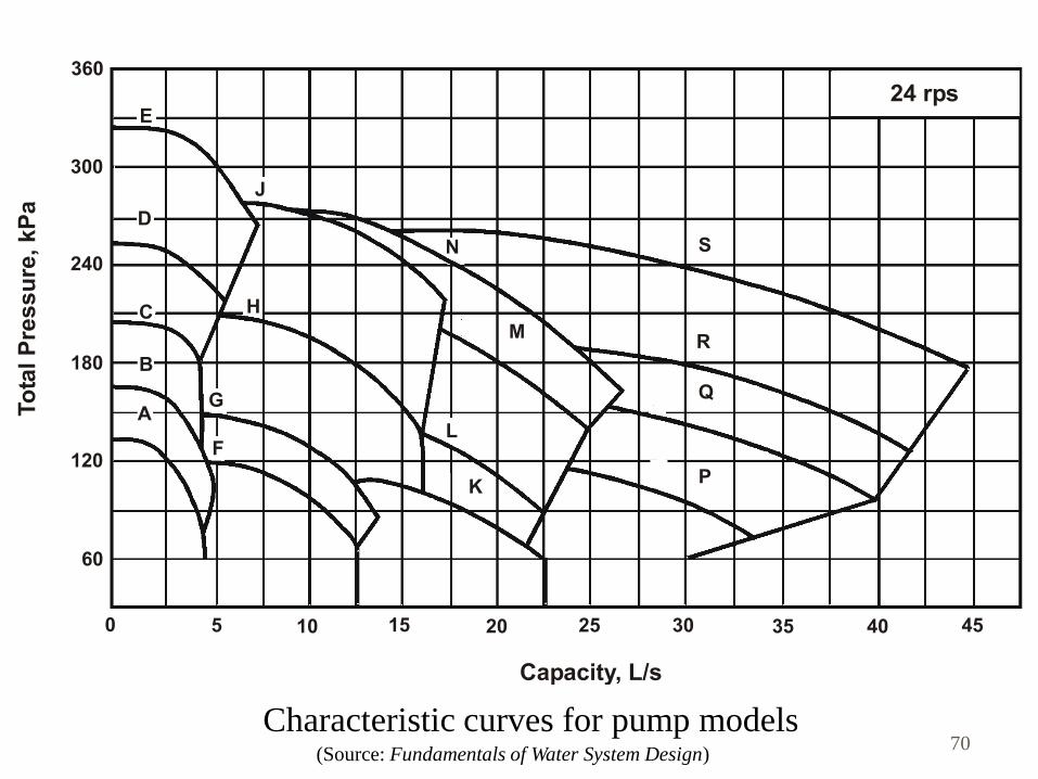
(Source: Fundamentals of Water System Design)
Characteristic curves for pump models 70
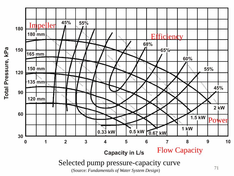
(Source: Fundamentals of Water System Design)
Selected pump pressure-capacity curve 71
Efficiency
Power
Flow Capacity
Impeller
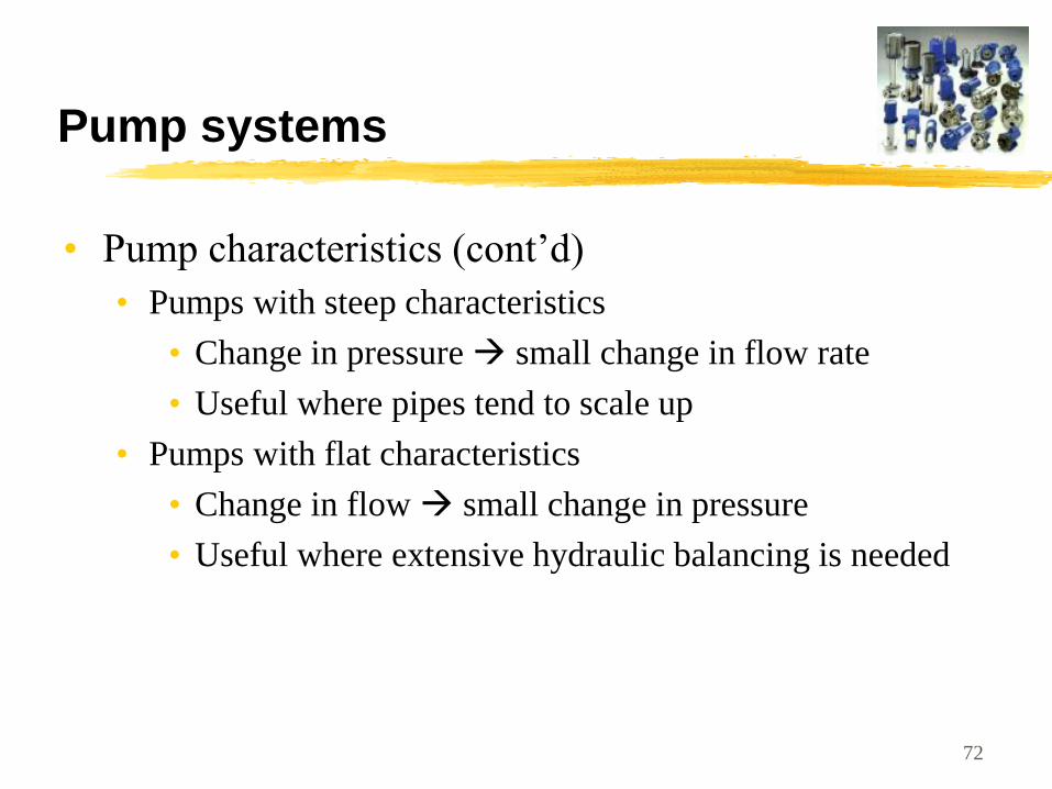
Pump systems
• Pump characteristics (cont’d)
• Pumps with steep characteristics
• Change in pressure small change in flow rate
• Useful where pipes tend to scale up
• Pumps with flat characteristics
• Change in flow small change in pressure
• Useful where extensive hydraulic balancing is needed
72
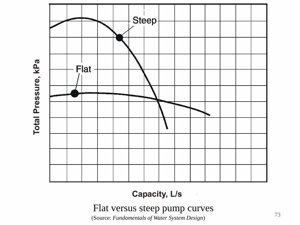
(Source: Fundamentals of Water System Design)
Flat versus steep pump curves 73
Pump systems
• Pump characteristics (cont’d)
• Constant Speed vs Variable Speed
• Pumps with constant speed cannot respond to changes
in load
• Require a bypass or a pipe restriction (e.g. a valve) to adjust
the flow
• Variable speed pumps
• Rotation speed reduces thus ‘point of operation’ changes
• Provides for savings in pumping costs during partial load
• Pump materials to suit the environment, e.g. stainless steel
pumps for salt water system
74
Other considerations
• Noise & vibration
• Pipe noise
• Pipe should not be fixed rigidly to lightweight panels
• Flow noise
• Keep velocities under control
• Pump noise
• Use rubber hose isolators, resilient inserts, acoustic
filters
75
Other considerations
• Water hammer
• Such as when a valve is closed rapidly
• Pulsating type of noise by shock waves
• Preventive measures:
• Prevent sudden closing of the valve
• Absorb pressure peaks (e.g. by pneumatic vessels)
• Increase the attenuation of pressure waves when
transmitted through the pipework
• Design the pipework to avoid long straight pipe runs
• Restrict water velocities (e.g. to a maximum of 3 m/s)
76
Other considerations
• Back siphonage
• Occur when water mains pressure reduce greatly
• Contamination of water may happen
• Contamination might also occur due to gravity &
backpressure backflow
• Anti-siphonage device and design precautions
77
Other considerations
• Water economy & energy conservation
• Economy of water
• A key factor in the design (to conserve water)
• Measures:
• Detect water leakage
• Reduce water consumption
• Reuse or recycle water
• Energy conservation
• Insulation of hot water pipe, fittings & vessels
• Use of fresh water for cooling tower make-up
78

Other considerations
• Water efficiency labeling scheme
• Water saving devices
• Low-flow showerheads
• Taps with flow restrictors
• Flow control valves
• Washing machines & dish-washers with high water efficiency
• Water plugs, self-closing taps, spray taps, aerators, etc.
79
Other considerations
• Water conservation (flushing water)
• Low-water and pressure flushing cisterns
• Dual-flush toilet cisterns
• Urinal controls
• Water reuse and recycling
• Rainwater reuse/recycling
• Grey water recycling
80
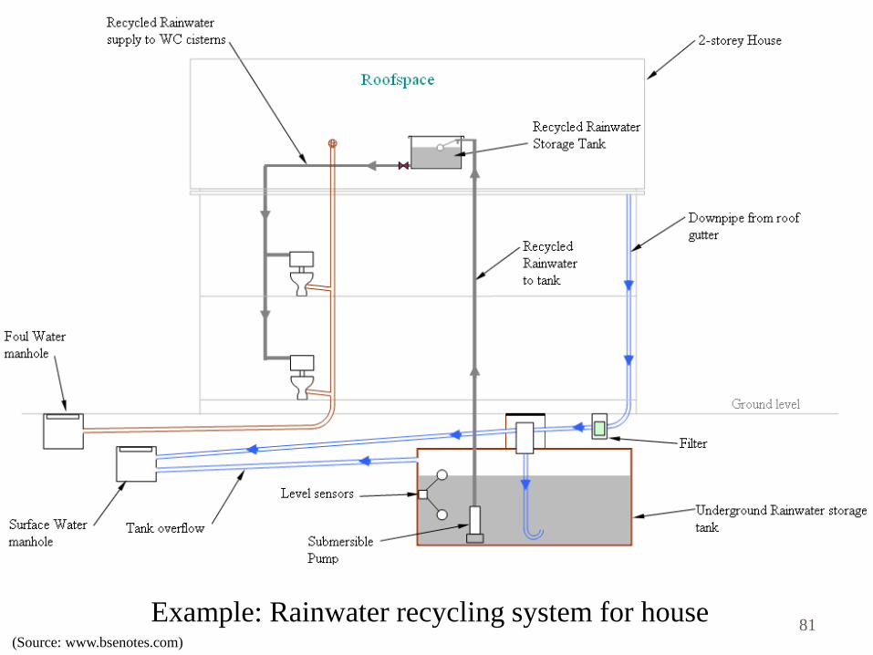
Example: Rainwater recycling system for house (Source: www.bsenotes.com)
81

82
End of Session