MEBS 6000 2010 Utilities services
18
MEBS 6000 2010 Utilities services M.Sc.(Eng) in building services Department of Electrical & Electronic Engineering University of Hong Kong K.F. Chan (Mr.) Page 1 of 18 18 July 2010 Joint speed torque characteristics of electric motors and mechanical loads Electric motors exhibit a variety of speed-torque characteristics that are suitable for a wide range of load demands. Mechanical loads also have a wide range of speed-torque characteristics depending on their mechanical properties. For example, the load torque of a hoist or a conveyor is largely independent of it speed. Load torque of a fan or a pump is proportional to the square of its speed. When an electric motor is connected to a mechanical load, the system operates at a speed-torque status that matches the characteristics of the motor as well as the mechanical load. Braking If no braking is applied to a motor, after electric power is removed, it only stops when all the kinetic energy is dissipated. Braking is a generic term used to describe a set of operating conditions for electric drive systems. It includes rapid stopping of the electric motor, holding the motor shaft, thus the driven equipment, to a specific position, etc. Besides mechanical braking, all these aspects of braking can also be done electrically. During braking, the energy flow changes its direction and utilization of the braking energy enhances system efficiency. Consider a PWM frequency inverter, in terms of power, the power input to the motor is: φ cos 3 VI P = where V is the phase to neutral voltage, I the phase current and φ the power factor. In motoring operation, φ <90 o , power is then positive and flows from the inverter to the motor. A reduction in frequency of the supply reduces the synchronous speed, before the rotor speed is reduced to the desired value, the rotor speed is higher than the synchronous speed. This reversal of relative speed reverses the rotor induced emf, rotor current and component of stator current which balances the rotor ampere turns. Consequently, the power factor φ >90 o , power becomes negative and flows from motor to the source. There are several forms of electric braking methods, collectively known as: 1. regenerative – feeding energy back to the power source, 2. dynamic – by dissipating the energy in an electrical resistance, 3. countercurrent – braking by reversing the direction of the stator field. We will discuss, briefly, dynamic braking and, more in detail, regenerative braking of ac induction motors.
Transcript of MEBS 6000 2010 Utilities services

MEBS 6000 2010 Utilities services M.Sc.(Eng) in building services
Department of Electrical & Electronic Engineering University of Hong Kong
K.F. Chan (Mr.) Page 1 of 1818 July 2010
Joint speed torque characteristics of electric motors and mechanical loads
Electric motors exhibit a variety of speed-torque characteristics that are suitable for a
wide range of load demands. Mechanical loads also have a wide range of
speed-torque characteristics depending on their mechanical properties. For example,
the load torque of a hoist or a conveyor is largely independent of it speed. Load torque
of a fan or a pump is proportional to the square of its speed. When an electric motor is
connected to a mechanical load, the system operates at a speed-torque status that
matches the characteristics of the motor as well as the mechanical load.
Braking
If no braking is applied to a motor, after electric power is removed, it only stops when
all the kinetic energy is dissipated. Braking is a generic term used to describe a set of
operating conditions for electric drive systems. It includes rapid stopping of the
electric motor, holding the motor shaft, thus the driven equipment, to a specific
position, etc. Besides mechanical braking, all these aspects of braking can also be
done electrically. During braking, the energy flow changes its direction and utilization
of the braking energy enhances system efficiency.
Consider a PWM frequency inverter, in terms of power, the power input to the motor
is:
φcos3VIP =
where V is the phase to neutral voltage, I the phase current and φ the power factor.
In motoring operation, φ <90o, power is then positive and flows from the inverter to
the motor. A reduction in frequency of the supply reduces the synchronous speed,
before the rotor speed is reduced to the desired value, the rotor speed is higher than
the synchronous speed. This reversal of relative speed reverses the rotor induced emf,
rotor current and component of stator current which balances the rotor ampere turns.
Consequently, the power factor φ >90o, power becomes negative and flows from
motor to the source.
There are several forms of electric braking methods, collectively known as:
1. regenerative – feeding energy back to the power source,
2. dynamic – by dissipating the energy in an electrical resistance,
3. countercurrent – braking by reversing the direction of the stator field.
We will discuss, briefly, dynamic braking and, more in detail, regenerative braking of
ac induction motors.
MEBS 6000 2010 Utilities services M.Sc.(Eng) in building services
Department of Electrical & Electronic Engineering University of Hong Kong
K.F. Chan (Mr.) Page 2 of 1818 July 2010
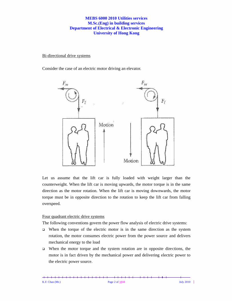
Bi-directional drive systems
Consider the case of an electric motor driving an elevator.
Let us assume that the lift car is fully loaded with weight larger than the
counterweight. When the lift car is moving upwards, the motor torque is in the same
direction as the motor rotation. When the lift car is moving downwards, the motor
torque must be in opposite direction to the rotation to keep the lift car from falling
overspeed.
Four quadrant electric drive systems
The following conventions govern the power flow analysis of electric drive systems:
When the torque of the electric motor is in the same direction as the system
rotation, the motor consumes electric power from the power source and delivers
mechanical energy to the load
When the motor torque and the system rotation are in opposite directions, the
motor is in fact driven by the mechanical power and delivering electric power to
the electric power source.

MEBS 6000 2010 Utilities services M.Sc.(Eng) in building services
Department of Electrical & Electronic Engineering University of Hong Kong
K.F. Chan (Mr.) Page 3 of 1818 July 2010
(Adopted from EL-SHARKAWI, M.A., Fundamentals of Electric Drives)
(Adopted from DUBEY, G.K. Fundamentals of Electrical Drives)
The above shows the four quadrants of speed-torque characteristics to cover all
possible combinations of any electric drive systems.

MEBS 6000 2010 Utilities services M.Sc.(Eng) in building services
Department of Electrical & Electronic Engineering University of Hong Kong
K.F. Chan (Mr.) Page 4 of 1818 July 2010
Quad
rant
Direction of
rotation
Load
torque and
rotation
Power flow Operating
as
Example
1st Same as 2nd
quadrant but
opposite to 3rd
Opposite
direction
From motor
to load
Motor Fully loaded
elevator moving
upwards
2nd Same as 1st
quadrant
Same
direction
From load
to motor
Generator Empty lift car
moving
upwards
3rd Opposite to 1st
quadrant
Opposite
direction
From motor
to load
Motor Empty lift car
moving
downwards
4th Opposite to 1st
quadrant but
same as 3rd
Same
direction
From load
to motor
Generator Fully loaded
elevator moving
downwards
A bi-directional grinding machine, a horizontal conveyor, a bi-directional travellator,
are all examples of machines required to operate in the 1st and 3rd quadrant.
Example of drive system operating in all four quadrants (Adopted from DUBEY, G.K. Fundamentals of Electrical Drives)
MEBS 6000 2010 Utilities services M.Sc.(Eng) in building services
Department of Electrical & Electronic Engineering University of Hong Kong
K.F. Chan (Mr.) Page 5 of 1818 July 2010
A versatile motor drive system operates in all 4 quadrants. An elevator carrying
passengers or a hoist with counterweight are typical examples. For maximum
efficiency, the power electronic circuit must then be designed to allow the electric
power to flow in both directions.
Four quadrant operation can be obtained by any drive system with braking capability.
A reduction of the inverter frequency, to make synchronous speed less than the
spinning rotor speed, transfers the operation from quadrant 1 (forward motoring) to
quadrant 2 (forward braking). The inverter frequency and voltage are progressively
reduced as speed falls to brake the machine to desired speed.
Next phase sequence of the inverter output voltage is reversed by interchanging the
firing pulses between any 2 legs of the inverter. This transfer the operation to quadrant
3 (reverse motoring). The inverter frequency and voltage are increased to get the
required speed in the reverse direction. Then a reduction of inverter frequency will
make the synchronous speed less than the spinning rotor speed, transferring operation
from quadrant 3 to 4 (reverse braking).
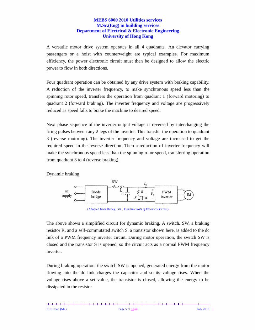
Dynamic braking
(Adopted from Dubey, G.K., Fundamentals of Electrical Drives)
The above shows a simplified circuit for dynamic braking. A switch, SW, a braking
resistor R, and a self-commutated switch S, a transistor shown here, is added to the dc
link of a PWM frequency inverter circuit. During motor operation, the switch SW is
closed and the transistor S is opened, so the circuit acts as a normal PWM frequency
inverter.
During braking operation, the switch SW is opened, generated energy from the motor
flowing into the dc link charges the capacitor and so its voltage rises. When the
voltage rises above a set value, the transistor is closed, allowing the energy to be
dissipated in the resistor.

MEBS 6000 2010 Utilities services M.Sc.(Eng) in building services
Department of Electrical & Electronic Engineering University of Hong Kong
K.F. Chan (Mr.) Page 6 of 1818 July 2010
Regenerative braking
Regenerative braking occurs when the motor speed exceeds the synchronous speed.
This may happen when the load torque drives the motor beyond its synchronous speed.
In this case, the load is the source of energy and the induction motor is converting the
mechanical power into electrical power, which is delivered back to the electrical
system.
If the power source of a frequency inverter comes from a rechargeable dc battery like
the one shown below, the circuit by its nature has the capability of regenerative
braking.
(Adopted from Dubey, G.K., Fundamentals of Electrical Drives)
However, if the power source comes from a ac/dc diode bridge like the one below,
some means shall be built into the frequency inverter drive to allow the regenerated
power during braking to return to the ac source.
(Adopted from Dubey, G.K., Fundamentals of Electrical Drives)

MEBS 6000 2010 Utilities services M.Sc.(Eng) in building services
Department of Electrical & Electronic Engineering University of Hong Kong
K.F. Chan (Mr.) Page 7 of 1818 July 2010
One method is to use dual converter in the power source section, one converting the
source ac to the dc link, the other one inverting the regenerated power in the dc link
back into the ac power source.
(Adopted from MURPHY, JMD, & TURNBULL, FG. Power electronic control of AC motors)

MEBS 6000 2010 Utilities services M.Sc.(Eng) in building services
Department of Electrical & Electronic Engineering University of Hong Kong
K.F. Chan (Mr.) Page 8 of 1818 July 2010
Another method is to use a synchronous link converter.
(Adopted from Dubey, G.K., Fundamentals of Electrical Drives)
Recall that diodes are typically installed across the transistors in the dc/ac inverter
section of a frequency drive to allow energy to flow back to the dc link. So one can
imagine that PWM inverter I, shown above in the power supply section, is an inverter
installed as a mirror image to PWM inverter II. PWM I and the inductor Ls constitute
a SLC.
PWM I is operated to produce voltage VI of required magnitude and phase – in phase
with Vs for motoring, and 180o out of phase with Vs for braking.
A SLI inverter schematics
MEBS 6000 2010 Utilities services M.Sc.(Eng) in building services
Department of Electrical & Electronic Engineering University of Hong Kong
K.F. Chan (Mr.) Page 9 of 1818 July 2010
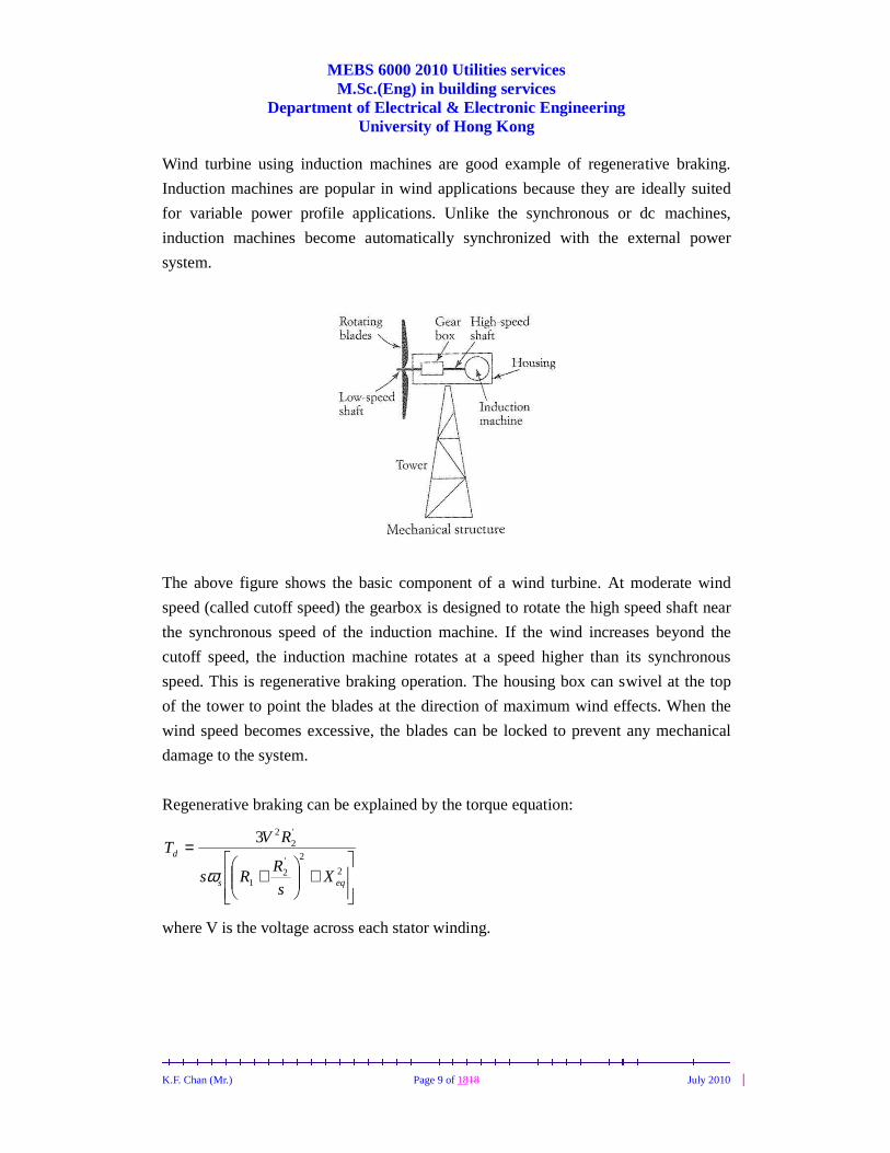
Wind turbine using induction machines are good example of regenerative braking.
Induction machines are popular in wind applications because they are ideally suited
for variable power profile applications. Unlike the synchronous or dc machines,
induction machines become automatically synchronized with the external power
system.
The above figure shows the basic component of a wind turbine. At moderate wind
speed (called cutoff speed) the gearbox is designed to rotate the high speed shaft near
the synchronous speed of the induction machine. If the wind increases beyond the
cutoff speed, the induction machine rotates at a speed higher than its synchronous
speed. This is regenerative braking operation. The housing box can swivel at the top
of the tower to point the blades at the direction of maximum wind effects. When the
wind speed becomes excessive, the blades can be locked to prevent any mechanical
damage to the system.
Regenerative braking can be explained by the torque equation:
+
+
=2
2'2
1
'2
23
eqs
d
Xs
RRs
RVT
ω
where V is the voltage across each stator winding.

MEBS 6000 2010 Utilities services M.Sc.(Eng) in building services
Department of Electrical & Electronic Engineering University of Hong Kong
K.F. Chan (Mr.) Page 10 of 1818 July 2010
The negative slip occurs when the speed of the machine exceeds the synchronous
speed:
s
s
n
nns
−=
When the turbine blades drives the electric machine to a speed faster than the
synchronous speed, the slip becomes negative. Since the load torque is in the same
direction as the machine, it operates in the 2nd quadrant as a generator. In fact,
induction machine of the wind system is designed to operate at regenerative braking
in the 2nd quadrant only. When the wind speed is low so that the rotor speed is near or
below the synchronous speed, the blades are locked and the motor is disconnected
from the electrical supply to prevent the machine from running as a motor.
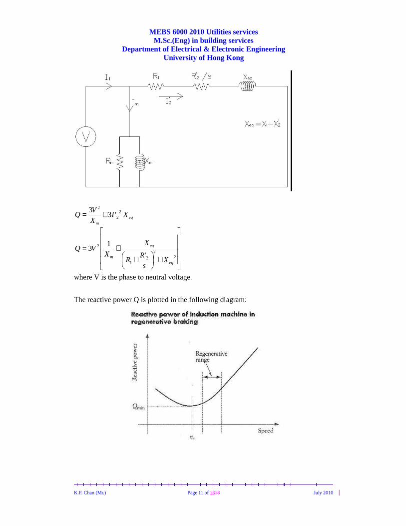
When used in wind applications, induction machines demand a significant amount of
reactive power from the utility system, mainly because they do not have their own
field circuit. When used in regenerative mode, the induction machine consumes
reactive power from the system while delivering real power. The inductive reactive
power Q is consumed in the magnetizing inductive reactance Xm and the equivalent
winding reactance Xeq.
MEBS 6000 2010 Utilities services M.Sc.(Eng) in building services
Department of Electrical & Electronic Engineering University of Hong Kong
K.F. Chan (Mr.) Page 11 of 1818 July 2010
eqm
XIX
VQ 2
2
2
'33 +=
+
++=
22
21
2
'
13
eq
eq
m Xs
RR
X
XVQ
where V is the phase to neutral voltage.
The reactive power Q is plotted in the following diagram:

MEBS 6000 2010 Utilities services M.Sc.(Eng) in building services
Department of Electrical & Electronic Engineering University of Hong Kong
K.F. Chan (Mr.) Page 12 of 1818 July 2010
Q is at its minimum at synchronous speed but is then almost linearly proportional to
speed when n>ns. To alleviate, a reactive power controller can be installed at the wind
farm.
In more general drive systems, the induction machine may operate in the first or
second quadrant only.
The above figure shows a constant but reversible load torque. When the load torque
changes from T1 to T2, the motor changes from 1st to 2nd quadrant operation, bear in
the mind that the motor is still rotating in the same direction.

MEBS 6000 2010 Utilities services M.Sc.(Eng) in building services
Department of Electrical & Electronic Engineering University of Hong Kong
K.F. Chan (Mr.) Page 13 of 1818 July 2010
The following figure shows another example. The figure shows 2 characteristics for
two different values of v/f control. The load torque is assumed to be constant. When a
speed reduction is desired from point 1, before the speed is changed, the motor
temporarily moves to operation point 2 in the 2nd quadrant under regenerative braking
then settles at point 3, the desired lower speed.

MEBS 6000 2010 Utilities services M.Sc.(Eng) in building services
Department of Electrical & Electronic Engineering University of Hong Kong
K.F. Chan (Mr.) Page 14 of 1818 July 2010
Example
A 400V, star connected, 3-phase, 6-pole, 50Hz induction motor has following
parameters referred to the stator:
R2’=R1=1Ω , X1=X2’=22Ω
For regenerative braking operation of this motor:
a) Determine maximum overhauling torque it can hold and range of speed for safe
operation.
b) Determine speed at which it will hold an overhauling load with a torque of
100Nm.
c) If a capacitive reactance of 2Ω is inserted in each phase of the stator, calculate
maximum overhauling torque the motor can hold as a ratio of maximum
overhauling torque without capacitor.
Answer
a) Synchronous speed = RPM10003
5060 =×=
3
502π =104.72rad/s
21
2
'2
maxRX
Rs
eq +±=
243.014
122max ±=
+±=s
For regenerative braking operation, the slip is negative, thus -0.243.
For generator action
++−
−=22
11
2
max
2
3
eqs XRR
VT
ω
[ ]22
2
max
411350
22
400
++−
−=
πT = -244.5Nm
Maximum torque occurs at smax of -0.243, i.e. at
(1+0.243)1000 = 1243RPM
Stable operation during regenerative braking occurs from synchronous speed to this
speed at which the torque is maximum. Thus range of speed for safe operation will
be from 1000 to 1243RPM.

MEBS 6000 2010 Utilities services M.Sc.(Eng) in building services
Department of Electrical & Electronic Engineering University of Hong Kong
K.F. Chan (Mr.) Page 15 of 1818 July 2010
b)
+
+
=2
2'2
1
'2
23
eqs
d
Xs
RRs
RVT
ω
Re-arranging, the above equation becomes
( ) 0''3
'2 22
22
21222
1 =+
−++ Rs
T
RVRRsXR
sdeq ω
Substituting the numerical values, the equation becomes
0126.1717 2 =++⇒ ss
Note that for a quadratic equation:
02 =++ cbxax
the solution can be written as:
a
acbbx
2
42 −±−=
So s = -0.957 or -0.063
However, -0.957 will give unstable operation, therefore s=-0.063.
Motor speed is thus
(1+0.063)1000 = 1063RPM
c)
If a capacitor is added per phase, the net effect is reducing the inductive reactance.
As 21
2
'2
maxRX
Rs
eq +±=
so ( )
447.0124
122max ±=
+−±=s
For generator action

MEBS 6000 2010 Utilities services M.Sc.(Eng) in building services
Department of Electrical & Electronic Engineering University of Hong Kong
K.F. Chan (Mr.) Page 16 of 1818 July 2010
++−
−=22
11
2
max
2
3
eqs XRR
VT
ω
( )
−++−
−=
22
2
max
2411350
22
400
πT =-618Nm
This is the maximum torque if a capacitor of 2Ω is added to each phase in series
with the stator winding. The ratio is
5.244
618
−−
=2.53
[This example adopted from Dubey, Gopal.K., Fundamentals of Electrical Drives]

MEBS 6000 2010 Utilities services M.Sc.(Eng) in building services
Department of Electrical & Electronic Engineering University of Hong Kong
K.F. Chan (Mr.) Page 17 of 1818 July 2010
Example
A 380V, 50Hz, six pole, star connected induction motor has the following parameters :
Ω=Ω=Ω= 5,4.0,6.0 '21 eqXRR
The motor is loaded by a 30 Nm bi-directional constant torque. If the load torque is
reversed, neglecting mechanical loss calculate
a) Motor speed
b) Power delivered to the electrical supply system
Answer
a) Phase to neutral voltage is V2203380 =
Synchronous speed is RPM10006
26050 =××
+
+
=2
2'2
1
'2
23
eqs
d
Xs
RRs
RVT
ω
Re-arranging, the above equation becomes
( ) 0''3
'2 22
22
21222
1 =+
−++ Rs
T
RVRRsXR
sdeq ω
Substituting the numerical values, the equation becomes
( ) ( )
+
+
=−
22
2
54.0
6.060
10002
4.0220330
ss π
( ) ( ) 016.097.1836.25 2 =++ ss
Note that for a quadratic equation:
02 =++ cbxax
The solution can be written as:
a
acbbx
2
42 −±−=
So s can be expressed as

MEBS 6000 2010 Utilities services M.Sc.(Eng) in building services
Department of Electrical & Electronic Engineering University of Hong Kong
K.F. Chan (Mr.) Page 18 of 1818 July 2010
( )( )( )22
1
22
221
2
22
212
2
21
2
'4'3
'2'3
'2
eq
eqsdsd
XR
RXRT
RVRR
T
RVRR
s+
+−
−±
−−
=ωω
Thus s = -0.0085 or -0.74
However, 21
2
'2
maxRX
Rs
eq +±= = 079.0±
Obviously, if the slip is -0.74, motor will run in unstable braking condition.
The regenerative speed is
( ) RPMsnn s 1009)0085.01(10001 =+=−=
b) ωTPd =
= Watt3170)60
10092)(30( =π
To calculate the stator and rotor copper loss we must first calculate the current '2I
Recall
gd PsP )1( −=
= )1(3'22'
2 ss
RI −
thus )0085.01()0085.0(
4.033170
2'2 +
−=− I
AmpI 72.4'2 =
So rotor copper loss is
WRI 7.26)4.0()72.4(33 2'2
2'2 ==
Stator copper loss is
WRI 1.40)6.0()72.4(33 21
2'2 ==
Therefore power delivered to the electrical system is
= 3170 – 26.7 – 40.1
=3103Watt
[Unless otherwise stated, text and figures adopted from EL-SHARKAWI, Mohamed
A., Fundamentals of Electric Drives]