MEASURING THE DIELECTRIC CONSTANTAND THE LOSS ANGLE … Bound... · SEPTEMBER 1951 I 61 MEASURING...
10
./ SEPTEMBER 1951 I 61 MEASURING THE DIELECTRIC CONSTANT AND THE LOSS ANGLE OF SOLIDS AT 3000 Mcfs by M. GEVERS. The dielectric properties of solids atfrequencies of some thousands of megacycles per second are interesting bothfrom the practical point of view - since decimetrio and centimetric radio waves have now found important practical applications - and from the 'theoretical-physicai point of view, for they help in giving an insight i~to the structure of a solid. .The method of measuring the dielectric constant and the loss angle is not new in principle but calls for an entirely new technique on account of the high frequencies occurring. Electromagnetic waves with a wavelength of about 10 cm (frequency 3000 Mc/s) have the proper- ty of being readily focused, so that they are highly suitable for radio communications between two fixed points and"for radar. Moreover, in that wave range an enormous number of channels arc available and therefore there will not so readily be that "congestion" which has to be con- tended with nowadays on the longer wavelengths. It was a long time, however, before the technique of the decimetric and centimetric waves, or the so-called ultra-high and super-frequencies, was sufficiently mastered. The fact that this may now he said to be the case - for a number of years already - is due in part to the results of the study that has been made of the properties of various constructional materials at these frequencies. The variation of the dielectric constant el} and of the loss "angle (J as a, function of the frequency has particularly been studied. When a dielectric is 'placed in an altérnating field with an r.m.s." value E and frequency f the. amount of heat "generated in the' dielectric per second is proportional to E2f e tan (J. From the proportionality with f it follows that e and tan IJ become particularly im- portant at high frequencies, -The amount of heat generated in a dielectric is_an important point of consideration, for instance, in the choice of the kind of glass to be used for the bulb of a transmitting valve; if the right kind is not chosen the glass may melt owing to excessive dielectric losses! Other examples are to he found in the various- kinds of insulators in cavity resonators, in coaxial cables and suchlike, the dielectric losses of which cause undesired damping and therefore have to be limited, tó the minimum. For these insulators certain plas-. 1) By e is understood here the real part of the complex dielec- tric constant. 621.317.335.3.029.63/.64 : 621.317.374.029.63/.64 tics or llIaterials of a ceramic nature are usually employed. The variation of tan (J as a function of the fre- quency is often erratic, so that in order to avoid unpleasant surprises the fueasurements have to be taken at the frequency at which. the insulating material is to be used. In this connection it is to be pointed out that knowledge of the dielectric properties of as many materials as possible in the widest possible frequency range is a matter of interest .not only to the tech- nician but' also to the physicist, -since it contri- butes towards the gaining of a better insight into the structure of solids 2). ,The method employed for measuring e and tan (J of solid dielectrics is a resonance method. When ,a rod (or disk) of the dielectric under investiga~ion is placed in the electric field of a resonant circuit the resonance curve of that circuit undergoes a change in two respects, namely a displàcement 'a:nd~à~'b-róadening. From the displacement it is possible to deduce the dielectric constant, and from the displacement and broadening together the loss angle can be determined 3}. This method, in itself well-known, will first be explained under the supposition that the frequency 2) See, e.g., M. Gevers and F. K. du Pr ë, A remarkable property oftechnical soliddielectrics, Philips Techn. Rev. 9, 91-96, 1947, dealt with more extensively in: M. Gevers, Philips Res. Rep. I, 197-224, 279-313, 361-379 and 44.7- 463, 1946. 3) In addition to the method described here, for determining the dielectric properties of solids at high' frequencies the Philips Laboratorles at Eindhoven also apply a method employing wave guides. The latter method is less,accurate than that described here but more suitable for still higher frequencies (10,000 Mets); for its description, see: H. G. , Beljers and W. J. van de Lindt, Dielectric measure- ments with two magic tees on shorted wave guides, Philips Res. Rep. 6, 96-104, 1951 (No. 2), and for the results of measurements taken with various kinds of glass, see: J. M. Stevels, Some experiments and theories on the power factor 'of glasses as a function of their composition, Philips Res. Rep. 5,23-36,1950 (No. 1) and 6, 34-53,1951 (No. I).
Transcript of MEASURING THE DIELECTRIC CONSTANTAND THE LOSS ANGLE … Bound... · SEPTEMBER 1951 I 61 MEASURING...
./
SEPTEMBER 1951I
61
MEASURING THE DIELECTRIC CONSTANT AND THE LOSS ANGLEOF SOLIDS AT 3000 Mcfs
by M. GEVERS.
The dielectric properties of solids at frequencies of some thousands of megacycles per secondare interesting both from the practical point of view - since decimetrio and centimetric radiowaves have now found important practical applications - and from the 'theoretical-physicaipoint of view, for they help in giving an insight i~to the structure of a solid. .The method ofmeasuring the dielectric constant and the loss angle is not new in principle but calls for anentirely new technique on account of the high frequencies occurring.
Electromagnetic waves with a wavelength ofabout 10 cm (frequency 3000 Mc/s) have the proper-ty of being readily focused, so that they arehighly suitable for radio communications betweentwo fixed points and" for radar. Moreover, in thatwave range an enormous number of channelsarc available and therefore there will not soreadily be that "congestion" which has to be con-tended with nowadays on the longer wavelengths.It was a long time, however, before the techniqueof the decimetric and centimetric waves, or theso-called ultra-high and super-frequencies, wassufficiently mastered. The fact that this may nowhe said to be the case - for a number of yearsalready - is due in part to the results of the studythat has been made of the properties of variousconstructional materials at these frequencies.The variation of the dielectric constant el} and
of the loss "angle (J as a, function of the frequencyhas particularly been studied. When a dielectricis 'placed in an altérnating field with an r.m.s."value E and frequency f the. amount of heat"generated in the' dielectric per second is proportionalto E2f e tan (J. From the proportionality with f itfollows that e and tan IJ become particularly im-portant at high frequencies, -The amount of heatgenerated in a dielectric is _an important point ofconsideration, for instance, in the choice of thekind of glass to be used for the bulb of a transmittingvalve; if the right kind is not chosen the glass maymelt owing to excessive dielectric losses! Otherexamples are to he found in the various- kinds ofinsulators in cavity resonators, in coaxial cablesand suchlike, the dielectric losses of which causeundesired damping and therefore have to be limited,tó the minimum. For these insulators certain plas-.
1) By e is understood here the real part of the complex dielec-tric constant.
621.317.335.3.029.63/.64 :621.317.374.029.63/.64
tics or llIaterials of a ceramic nature are usuallyemployed.
The variation of tan (J as a function of the fre-quency is often erratic, so that in order to avoidunpleasant surprises the fueasurements have tobe taken at the frequency at which. the insulatingmaterial is to be used.
In this connection it is to be pointed out thatknowledge of the dielectric properties of as manymaterials as possible in the widest possible frequencyrange is a matter of interest .not only to the tech-nician but' also to the physicist, -since it contri-butes towards the gaining of a better insight intothe structure of solids 2)., The method employed for measuring e and tan (J
of solid dielectrics is a resonance method. When, a rod (or disk) of the dielectric under investiga~ionis placed in the electric field of a resonant circuitthe resonance curve of that circuit undergoes achange in two respects, namely a displàcement'a:nd~à~'b-róadening. From the displacement it ispossible to deduce the dielectric constant, andfrom the displacement and broadening togetherthe loss angle can be determined 3}.
This method, in itself well-known, will first beexplained under the supposition that the frequency
2) See, e.g., M. Gevers and F. K. du Pr ë, A remarkableproperty of technical soliddielectrics, Philips Techn. Rev. 9,91-96, 1947, dealt with more extensively in: M. Gevers,Philips Res. Rep. I, 197-224, 279-313, 361-379 and 44.7-463, 1946.
3) In addition to the method described here, for determiningthe dielectric properties of solids at high' frequencies thePhilips Laboratorles at Eindhoven also apply a methodemploying wave guides. The latter method is less,accuratethan that described here but more suitable for still higherfrequencies (10,000 Mets); for its description, see: H. G.
, Beljers and W. J. van de Lindt, Dielectric measure-ments with two magic tees on shorted wave guides, PhilipsRes. Rep. 6, 96-104, 1951 (No. 2), and for the results ofmeasurements taken with various kinds of glass, see: J. M.Stevels, Some experiments and theories on the powerfactor 'of glasses as a function of their composition, PhilipsRes. Rep. 5,23-36,1950 (No. 1) and 6, 34-53,1951 (No. I).
62 PHILlPS TECHNICAL REVIEW - VÓL. 13, No. 3
at which the measurements are taken is not veryhigh (say 1 Mcfs), so that a normal resonant circuitcan be employed consisting of lumped inductanceand capacitance. Then the modifications -will bediscussed which are necessary when for a frequencyof, say, 3000 Mcfs the circuit has to be replacedby a cavity resonator 4).
Measuring with á normal resonant circuit
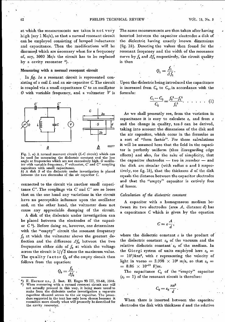
In fig. la a resonant circuit is represented con-sisting of a coil L and an air-capacitor C.The circuitis coupled via a small capacitance C' to an oscillatoro with variable frequency, and a voltmeter V is
c' c·
o v
c I 2aI
-5 Id2b
Fig. La) A normal resonant circuit (L-C circuit) which canhe used for measuring the dielectric constant and the lossangle at frequencies which are not excessivelyhigh. 0 oscilla-tor with variable frequency, V voltmeter, C' and C" couplingcapacitors with small capacitance.b) A disk S of the dielectric under investigation is placedbetween the two electrodes of the air capacitor C.
connected to the circuit via another small capaci-tance C". The couplings via C' and CIf are so loosethat on the one hand any variations in the circuithave no perceptible influence upon the oscillatorand, on the other hand, the voltmeter does notcause any appreciable damping of the circuit.A disk of the dielectric under investigation can
be placed between the electrodes of the capaci-or C ó). Before doing so, however, one determineswith the "empty" circuit the resonant frequency10 at which the voltmeter shows the greatest de-flection and the difference Afo between the twofrequencies either side of 10 at which the voltageacross the circuit is lff'i. times the maximum value.The quality factor Qo of the empty circuit thenfollows from the equation:
Qo= 10 .Llfo
. 4) F. Horner c.s., J. Inst. El. Engrs 93 Ill, 53,68, 1946.5) When measuring with a normal resonant circuit one will
not actually proceed in this way, it being more usual tomake from the dielectric under investigation a separatecapacitor shunted across to the air 'capacitor. The proce-dure suggested in the text has only been chosenbecause itresemblesmore closelywhat will presently be described forthe cavity resonat.?r.
The same measurements are then taken after havinginserted between the' capacitor electrodes a disk ofthe dielectric having exactly known dimensions(fig. lb). Denoting the values then found for theresonant frequency and the width of the resonancecurve by f1 and iJA respectively, the circuit qualityis then .
Q1 = _h_'.iJf1
Upon the dielectric being introduced the capacitanceis increased from Co to Cl' in accordance with theformula: .
C1- Co fo2-f12(1)
65577
As we shall presently see, from the variation incapacitance it is easy to calculate e, and from sand the change in quality, tan ~ can be derived,taking into account the dimensions of the disk andthe air capacitor, which occur in the formulae asa sort of "form factor". For these calculationsit will be assumed here that the field in the capaci-tor is perfectly uniform (thus disregarding edgeeffects) and also, for the sake of simplicity, thatthe capacitor electrodes - two in number - andthe disk are circular (with radius a and b respec-tively, see fig. lb), that the thickness d of the diskequals the distance between the capacitor electrodesand that the "empty" capacitor is entirely freeof losses.
Calculation of the dielectric constant
A capacitor with a homogeneous medium be-tween its two electrodes (area A, distance d) hasa capacitance C which is given by the equation
AC=e-,
d
where the dielectric constant e is the product ofthe dielectric constant eo of the vacuum and therelative dielectric constant' er ot the medium. Inthe Giorgi system of units employed here eo -= 107 f4nc2, with c representing the velocity oflight in vacuo = 2.998 X lOSmfs, so that eo == 8.86 X 10⁻¹² Ffni.The capacitance Co of the ~'empty" capacitor
(er = 1) of the resonant circuit is therefore:
When there is inserted, between the capacito ...·electrodes the disk with thickness d and the relative
,-
SEPTEMBER 1951 MEASURING s AND e AT 3000 Mcls 63
dielectric constant er (to he determined), the capa-citance is:
na2- nb2 nb2 nC1=eO d +eo·erd=eod(a2-b2+erb2).
Thus
In comhination with equation (1) this gives:
in which (a/b)2 might he termed the "form factorof the dielectric constant" (or rather of er '- 1).
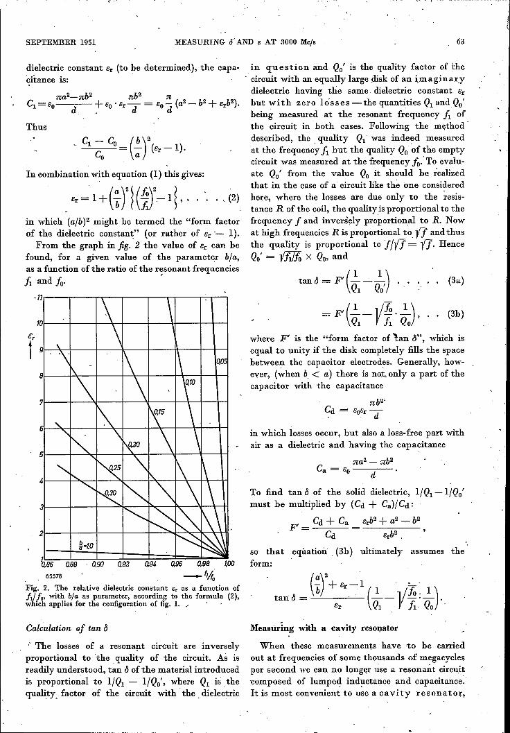
From the graph in jig. 2 the value of er can hefound, for a given value of the parameter bla,as a function of the ratio of the resonant frequencies.ft 'and 10· I
-11r---.----,-"T"""-r----r--"T"""T--...-'-~.....,
f~~~--+-~~~~~a
hB5 0,88 ,0,90 0,9205578
a9~ 0,95
Fig. 2. The relative dielectric constant Er as a function offd fo' with bl« as parameter, according to the formula (2),which applies for the configuration of fig. 1." , .
Calculation of tan Cl
.. The losses of a resonant circuit are inverselyproportional to 'the, quality of the circuit. As isreadily understood, tan Clof the material introducedis proportional to l/Ql - l/Qo', where Ql is thequality. factor of the circuit with' the. dielectric
in question and Qo' is the quality factor of the- circtiit withan equally large disk of an im agin arydielectric having the same dielectric constant erhut with zero lósses -the quantities Ql andQo'being measured at the resonant frequency fl ofthe circuit in hoth cases. Following the methoddescrihed, the quality Ql' was indeed measuredat the frequency f1 hut the quality Qo'of the emptycircuit was measured at the frequency i: To evalu-ate Qo' from the value Qo it should he realizedthat in the case of a circuit like the one consideredhere, where the losses are due only to the resis-tance R of the coil, the quality is proportional to thefrequency f and inversely proportional to R. Nowat high frequencies R is proportional to, -vl and thusthe quality is proportional to fNl = -Vl. HenceQo'= -vfl/fo X Qo, and "
. ( 1 1)'tan d = F' --- ...Ql Qo' .
(3a)
=F'(~l-Vj:·~J, .. (3h)
where F' is the "form factor of 'lan Cl", which isequal to unity if the disk completely fills the spacehetween the capacitor electrodes. Generally, how-ever, (when b < a) there is not, only a part of thecapacitor with the capacitance
nb2'Cd ==':
in which losses occur, hut also a loss-free part withair as a dielectric and having the capacitance
na2 - nb2Ca = eo d
To find tan Clof the solid dielectric, l/Ql -l/Qo'must he multiplied hy (Cd + Ca)/ Cd :
Cd + Ca erb2 + a2 - b2[t" eee" = ------
Cd .»,so that equation' (3h) ultimately assumes theform:
Measuring with a cavity resonator
When these measurements have ,to he carriedout at frequencies of some thousands of megacyclesper second we can no Iongor use a resonant circuitcomposed of lumped inductance and capacitance.It is most convenient to use a cavity resonator,
64 PHILIPS TECHNICAL REVIEW VOL. 13, No. 3
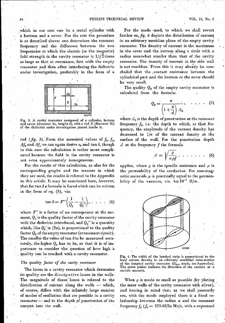
.which in our case can be a metal cylinder with .a bottom and a cover. For the rest the procedureis as described above: one determines the resonantfrequency and the difference. "between the twofrequencies at which "the electric (or the magnetic]field strength in the cavity resonator is 1fl/2 timesas large as that at resonance, first with the emptyresonator and then after introducing the dielectricunder investigation, preferably in the form of a
2bd ,
5 2a
~65579
Fig. 3. A' cavity resonator composed of a cylinder, bottomand cover (diameter 2a, height d), with a rod S (diameter 2b)of the dielectric under investigation placed inside it.
rod (fig. 3). From the measured values of fo, f1tLJfo and LJf1 we can again derive Er and tan ö, thoughin this case the calculation is rather more compli-cated because the field in the cavity resonator isnot even approximately homogeneous.
For the results of this calculation, as also for thecorresponding graphs and the manner in whichthey are used, the reader is referred to the Appendixto this article. Itmay be mentioned here, however,that for tan ö a formula is found which can be writtenin th~ form of eq. (3), viz:
(I I )
tan Ö= F" Q1 - Qo" '
where F" is a factor of no consequence at the mo-ment, Q1 is the quality factor of the cavity resonatorwith the dielectric introduced, and 'Qo" is a quantitywhich, like Qo' in (3a), is proportional to the qualityfactor Qo of th~ empty resonator (or resonant circuit).The smalle~ the value of tan Ö to be measured accu-rately, the higher Qo has to be, so that it is of im-portance to consider the question of how high aquality can be reached with a cavity resonator.
.'
The quality factor of the cavity resonator
The losses in a cavity resonator which determineits quality are the dissipative losses in the walls.The" magnitude of these' losses is related to thedistribution of current along the walls - wliich,of course, differs with the infinitely large numberof modes' ~f oscillation that are possible in a. cavityresonator - and to the depthof penetration of thecurrent into the wall.
For the mode -used, to which we shall revertfarther on, fig. 4 depicts the distribution of currentin an arbitrary meridian plane of the empty cavityresonator. The density of current is the maximumin the cover and the hottorn along a circle with aradius somewhat smaller than that of the. cavityresonator. The density of current in the side wallis not muchless. From this it may already be con- .eluded that the. contact resistance between thecylindrical part and the bottom or the cover shouldbe very small. .
'I'he quality Qo of the empty cavity resonator iscalculated from the formula:
Q, . (1+~)LI,where LJo is the dep!h of penetration at the resonantfrequency 10, i.e. the depth to which, at that fre-quency, the amplitude of the current density h~sdecreased to lie of the current density at thesurface of the wall.' For the penetratien depthLJ at the frequency f the formula
(5)
LJ = 1/ (! ••. n/kJ
(6)
applies, where (! is the specific resistance and fJ, isthe permeability of the conductor. For non-m_ag-netic materials fJ, is practically equal to the permea-bility of the vacuum, viz. 4n·IO-7 Hjm.
(4)
Fig. 4,. The width of the hatched strip is proportional to thelocal current density in an arbitrary meridinal cross sectionof the (empty) cavity.resonator (EolO mode, seeAppendix).The arrow points indicate the direction of the current at' acertain moment.
When (! is made as small as possible (by platingthe inner walls of the cavity resonator with silver),'and bearing in mind that, a~ we shall presentlysee, with the mode employed there is a fixed re-lationship between the radius a and the resonantfrequency fo (10= 229.49/2a Mc/s, with a expressed
SEPTEMBER 1951 MEASURING s AND e AT 3000 Mcts 65
in metres}, it appears that in the formula for Qoonly the height d of the cavity resonator is avail-able. From this equation (5) it is seen that increas-ing the value of d improves the quality, but thereis a limit set to the height, because if it is made toolarge, then óther, undesired, modes may easilyoccur in the cavity resonator. Besides, if d is greaterthan á any futher increase of d would, as a matterof fact, yield onlya slight improvement in quality,and moreover a tall cavity resonator with the de-sired extremely high quality is far more difficultto make than a' low one.
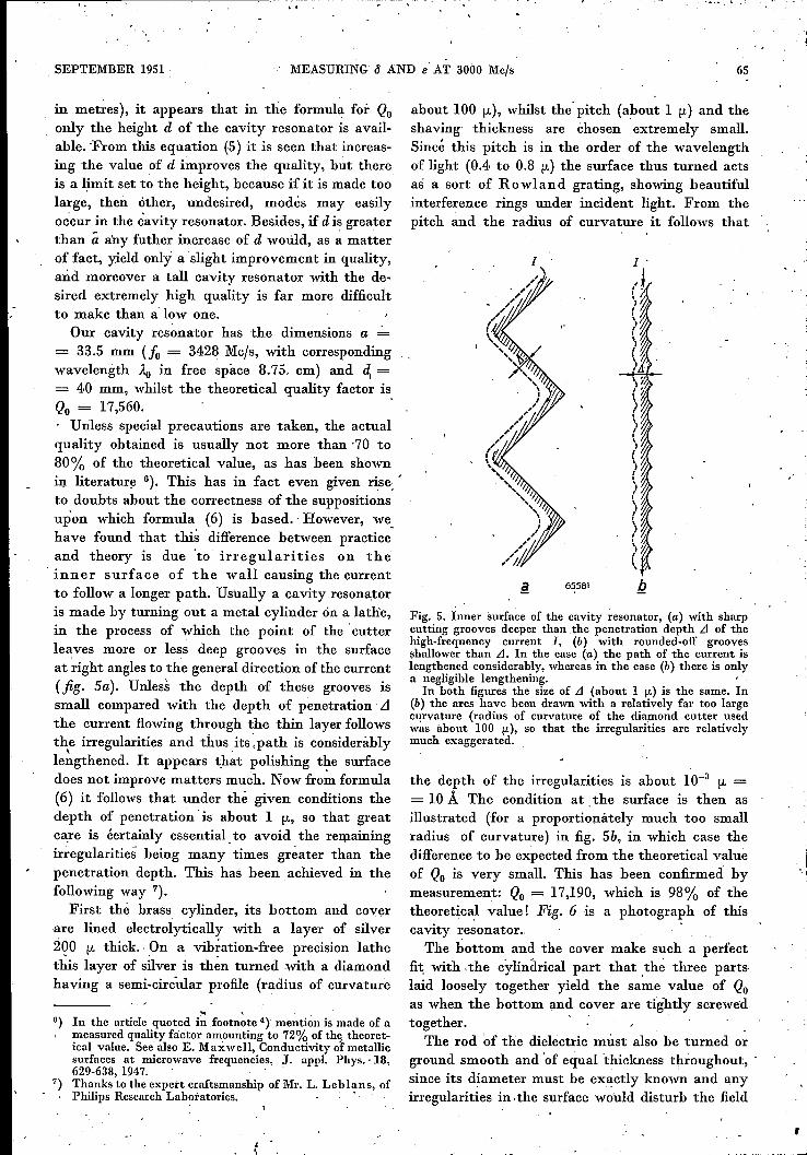
Our cavity resonator has the dimensions a= 33.5 mm (Jo = 3428 Mc/s, with correspondingwavelength Ao in free space 8.75. cm) and ~ == 40 mm, whilst the theoretical quality factor isQo = 17,560. .. Unless special precautions are taken, the actualquality obtained is usually not more than '70 to80% of the theoretical value, as has been shown:IT" lirerature 6). This has in fact even given rise:to doubts about the correctness of the suppositionsupon which formula (6) is based.' However, we.have found that this difference between practiceand theory is due 'to irregularities on theinner surface of the wall causing the currentto follow a longer path. Usually a cavity resonatoris made by turning out a metal cylinder ón a lathe,in the process of which the point of the 'cutterleaves more or less deep grooves in the surfaceat 'right angles to the general direction of the current(fig. Sa). Unless the depth of these grooves issmall compared 'with the depth of penetration LIthe current flowing through the thin layer followsthe irregularities and thus its.path is consideràbly, '
lengthened. It appears that polishing the surfacedoes not improve matters much. Now from formula(6) it follows that under the given conditions thedepth of penetratien is about 1 fL, so that greatcare is éertainly essential to avoid the remainingirregularities being many times greater than thepenetration depth. This has been achieved in thefollowing way 7).
First the brass cylinder, its bottom and coverare lined electrolytically with a layer of silver2QO fL thick. On a vibration-free precision lathethis layer of silver is then turned with a diamondhaving a semi-eireular profile (radius of curvature
.. ,6) In the article quoted in .footnote 4) mention is made of a
measured quality factor amounting to 72% of the theoret-ical value. See also E. Maxwell, Conductivity ot metallicsurfaces at microwave frequencies, J. appl. Phys. ·18,629-638, 1947.
7) Thanks to the expert craftsmanship of Mr. L. Leblans, ofPhilips Research Lab?tatories. . ,
about 100 fL), whilst the' pitch (about 1 fL) and theshaving" thickness are chosen extremely small.Sincé this pitch is in the order of the wavelengthof light (0.4 to 0.8 fL) the surface thus turned actsas a sort of Rowland grating, showing beautifulinterference rings under incident light. From thepitch and the radius of curvature it follows that
I
65581
Fig. 5. Inner surface of the cavity resonator, (a) with sharpcutting grooves deeper than the penetration depth .1 of thehigh-frequency current I, (b) with rounded-off groovesshallower than .1. In the case (a) the path of the current islengthened considerably, whereas in the case (b) there is onlya negligible lengthening. 'In both figures the size of .1 (about 1 (L) is the same. In
(b) the arcs have been drawn with a relatively far too largecurvature (radius of curvature of the diamond cutter usedwits about 100 (L), so that the Irregularities are relativelyllluch exaggerated.
the depth of the irregularities is about 10-3 fL == 10 Á The condition at the surface is then asillustrated (for a proportionàtely much too smallradius of curvature) in fig. Sb, in which case thedifference to be expected from the theoretical valueof Qo is very small. This has been confirmed bymeasurement: Qo = 17,190, which is 98% of thetheoretical value! Fig. 6 is a photograph of thiscavity resonator.The bottom and the cover make such a perfect
fit; with .the cylindrical part that .thé three partslaid loosely together yield the same value of Qoas when the bottom and cover are tightly screwedtogether. .
The rod 'of the dielectric must also be turned orground smooth and 'of equal thickness throughout, .since its diameter must be exactly known' and anyirregularities in. the surface would disturb the field
,
66 PHILIPS TECHNICAL REVIEW VOL. 13, No. 3
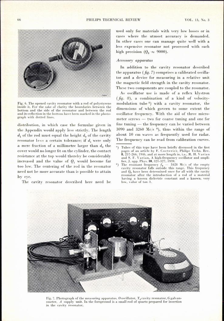
Fig. 7. Photograph of the measuring apparatus. 0 oscillator, T2 cavity resonator, G galvan-ometer, A supply unit. In the foreground is a small rod of quartz prepared for insertionin the cavity resonator.
Fig. 6. The opened cavity resonator with a rod of polystyreneinside it. For the sake of clarity the boundaries between thebottom and the side of the resonator and between the rodand its reflection in the bottom have been marked in the photo-graph with dotted lines.
distribution, in which case the formulae given inthe Appendix would apply less strictly. The lengthdl of the rod must equal the height do of the cavityresonator less a certain tolerance; if dl were onlya mere fraction of a millimetre larger than do thecover would no longer fit on the cylinder, the contactresistance at the top would thereby be considerablyincreased and the value of QI would become fartoo low. The centering of the rod in the resonatorneed not be more accurate than is possible to attainby eye.
The cavity resonator described here need be
used only for materials with very low losses or incases where the utmost accuracy is demanded.In other cases one can manage quite well with aless expensive resonator not processed with suchhigh precision (Qo'~ 9000).
Accessory apparatus
In addition to the cavity resonator describedthe apparatus (fig. 7) comprises a calibrated oscilla-tor and a device for measuring in a relative unitthe magnetic field strength in the cavity resonator.These two components are coupled to the resonator.As oscillator use is made of a reflex klystron
(fig. 8), a combination of a kind of velocity-modulation tube 8) with a cavity resonator, thedimensions of which govern to some extent theoscillator frequency. With the aid of three micro-meter screws - two for coarse tuning and one forfine tuning - the frequency can be varied between3090 and 3260 Mc/s 9), thus within the range ofabout 10 cm waves as frequently used for radar.The frequency can be read from calibration curves.
q) Tubes of this type have been briefly discussed in the firstpages of an article by F. Coeterier, Philips Techn. Rev.8,257-266,1946, and at more length in, i.a., R. H. Varianand S. F. Va ri a n , A high-frequency oscillator and ampli-fier, J. app. Phys.lO, 321-327, 1939.
2) The resonant frequency Jo = 34,28 Mc/s of the emptycavity resonator falls outside this range. This frequencyand Qo have been determined once for al! with the cavityresonator after the introduction of a rod of a materialhaving a known dielectric constant and a known, verylow, value of tan Ö.
SEPTEMBER 1951
N, V, PHIUPS' G10EllAMPENFABRIEK~MEASURING 0 AND e AT 3000 Mcls
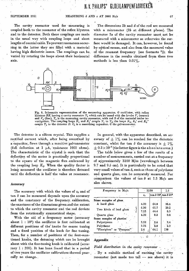
The cavity resonator used for' measuring iscoupled both to the resonator of the reflex klystronand to the detector. Both these couplings are madein the usual way with coupling loops and shortlengths of coaxial cable. To preventresonances occur-ring in the hitter they are filled with a materialhaving high 'dielectric losses. The couplings can he,varied by rotating the loops about their horizontalaxis.
The dimensions 2b and d of the rod are measuredwith a micrometer (2b at different places). Thediameter 2a of-the cavity resonator must. not bemeasured with a micrometer as otherwise the sur-face would be damaged. It can, however, be foundby optical means, and also from the measured val}leof the resonant frequency (see footnote 9)); thedifference in the results obtained from these twomethods is less than 0.01%.
.'
65584
Fig. 8. Schematic representation of the measuring apparatus. 0 oscillator, with reflexklystron RK having a cavity resonator Tl which can be tuned with the knobs VI (coarse)and V2 (fine). T2 is the measuring cavity resonator, with rod S of the material under in-vestigation. The coupling loops Kl and Kl' couple Tl to T2; the loops K2, K2' and K2"
couple T2 to the detector D. Cl is a smoothing capacitor. G the galvanometer.
The detector is a silicon crystal. This supplies arectified current which, after being smoothed bya ~apacitor, flows through a sensitive 'galvano~eter(full deflection at 1 !LA,'resistance 1000 ohms).The characteristic of the crystal i~ such that thedeflection of the meter is practically proportionalto' the' square of the magnetic flux. embraced bythe coupling loop 1(2' When the quality factor isbeing measured the oscillator is therefore 'détuneduntil the deflection is half the value at resonance.
Accuracy
The accuracy with which the values of Br and oftan d can be measured depends upon the accuracyand the constancy of the frequency, calibration,the exactness of the dimensions given and the extentto which the cavity resonator and the rod deviatefrom the rotationally symmetrical shape.
With the aid of a frequency meter (accuracyabout 1 : 106) the oscillator is first calibrated atdifferent positions of the' knobs for coarse tuning,and a fixed position of the knob for fine tuning.Then, for a number of positions of the first-men-tioned knobs, the detuning which can be brought. about with the fine-tuning knob is calibrated (accu-racy 1 : 200). It has been found that in a periodof two years the oscillator calibrations showed prac- .cally no change ..
I,r.
In general, with the apparatus described, an ac-curacy of ± 1% can be reached for the dielectricconstant, whilst for tan d the accuracy is ± 1%.± 0.2 X 10⁻⁴ (the latter fig~re is the ab solute error.)The table below gives a few of the results of a
number of measurements, carried out at a frequencyof approximately 3100 Mies (wavelength between9.7 and 9.5 cm). It is particularly to 'be noted thatvery small values of tan d, such as those of polytheneand quartz glass, can be accurately measured. Forcomparison the value~ of tan d at 1.5 Mcls arealso sh~wn·.
Frequency in Mcls 31ÓO I 1.5er Itan 0.1041tan 6.104
Some samples. of glass.A hard glass. 4.20 .64.8 36.4
Two kinds of lead glass 6.30 6Î.7 20.27.15 44.4 8.9
Quartz glass 4.20 0.8 0.8Some samples of plastics'Polystyrene 2.52 2.6 2.4Polythene 2.25 2.0 2.0"Plexiglass" or "Perspex" 2.6 ; . 64.1 130. .
Appendix
Field distribution tn the cavity resonator
, By a suitable method of exciting 'the cavityresonator (not made too tall - see above) it is
67
68 PHILIPS TECHNICAL REVIEW VOL. 13, No. 3
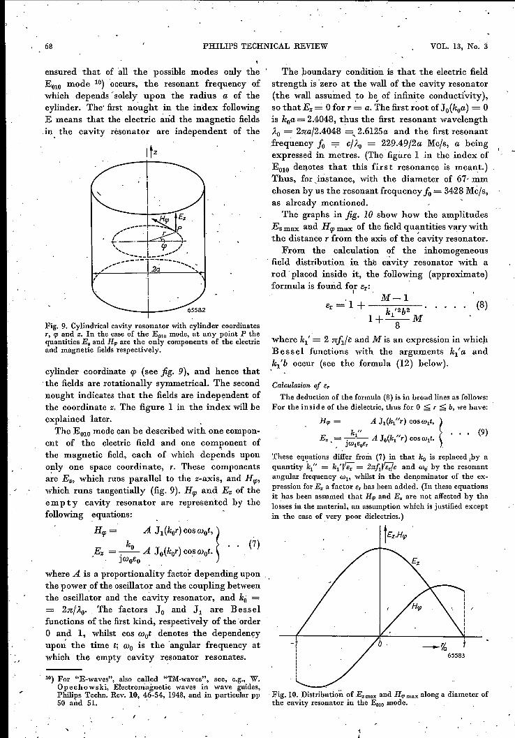
ensured that of all the possible modes only the 'EOIO mode 10) occurs, the resonant frequency ofwhich depends' solely upon the radius a of thecylinder. The' first nought in the index followingE means that the electric and the magnetic fieldsin the cavity resonator are independent of the
F:ig.9. Cylindrical cavity resonator with cylinder coordinatesr, rp and z, In the case of the EOlo mode, at any point P thequantities E. and H", are the only components of the electricand magnetic fields respectively.
cylinder coordinate gJ (see fig. 9), and hence thatthe fields are rotationally symmetrical. The secondnought indicates that the fields are independent ofthe coordinate z. The figure 1 in the index will beexplained 'later.
The E010mode can be described with one compon-ent of the electric field and one component ofthe magnetic field, each of which depends upononly one space coordinate, r, These componentsare Ez, which runs parallel to the z-axis, and Hrp,which runs tangentially (fig. 9). Hrp and Ez of theempty .cavity resonator are represerrted by thefollowing equations:
Hrp = ko A J1(kor) coswot,! (7)
,Ez = -.- A Jo(kor) cO,swot.JWoBo
where A is a proportionality factor depending uponthe power of the oscillator and the coupling betweenthe oscillator and the cavity resonator, and ko == 2nlÄo' The factors Jo and J1 are Besselfunctions of the first kind, respectively of the ordero and 1, whilst cos wot denotes the dependency
. upon: the time t; Wo is the 'angular frequency atwhich the empty cavity resonator resonates.
10) For "E-waves", also cal\ed "TM-waves", see, e.g., W.Opechowski, Electromagnetic waves in wave guides,Philips Techn. Rev. 10, 46-54, 1948, and in particular pp50 mid 51. '
The boundary condition is that the electric fieldstrength is' zero at the wall of the cavity resonator(the wall assumed ,to be"of infinite conductivity),so that Ez = 0 for r = a. The first root of Jo(koa) = 0is koa = 2.4048, thus the first resonant wavelengthÄo= 2na/2.4048 ,2.6125a and the first resonant.frequency Jo .--:- cl Äo = 229.49/2a Mc/s, a beingexpressed in metres. (The figure 1 in the index ofEOlO denotes that this first resonance is meant.)Thus, for 5nstance, with the diameter of 67· mmchosen by us the resonant frequency Jo= 3428 Mè/s,as already mentioned.
The graphs in fig. 10 show how the amplitudesEz max and Hrp max of the field quantities vary withthe distance r from the axis of the cavity resonator.
From the calculation of the inhomogeneousfield distribution in the cavity resonator with a:rod placed inside it, the following (approximate)formula is found for Br: .. I .
M-IB -' 1+---:--::-r - k '2b2
l+_l_M8
(8)
where k1' = 2 niI/c and M is an expression in whichBessel functions with the arguments k1'a and.k1'b occur (see the formula (12) below).
Calculation of Br
The deduction of the formula (8) is in broad lines as follows:For the inside of the dielectric, thus for 0 ;:£; r ;:£; b, we have:
H", = A J1(~"r) cosw1t, !~" " . • . (9)
E= , =-.-- AJo(~ r)cosw1t., JW1BoEr .
These equations differ from (7) in that ko is replaced .by aquantity ~" = k1'IIE." = 2nfJEJc and ClIo' by the resonantangular frequency W1' whilst in the denominator of the ex-pression for E. a factor Er has been added. (In these equationsit has been assumed that H", and E. are not affected by thelosses in the material, an assumption which is justified exceptin the case of very poor dielectrics.)
tEz.HqJ
--%65583
. Fig.IO. Distribution of E.m." and H",mux along a diameter ofthe cavity resonator in the EOlOmode.
SEPTEMBER 1951 MEASURING s AND e AT 3000 Mcjs 69
In the reni~ining p ;rt of the cavity resonator (b ~ r ~ a)the following equations applyr .
n; . ~B J1(k1'r) + CY1(k1'r)(cosw1t,(~' . (10)s; -.- ~B JO(k1'r) + CYo(~'r)(coswlt,
]wleO
where Yo and Y1 are Bessel functions of the second kind,respectively of the order 0 and 1. The ëonstants Band Care proportional to A and can be eliminated with the aidof the boundary conditions. Th~se are as follows: for r .= aagain Ez must equal 0, and at the boundary between the soliddielectric and air Ez and Hq>must be continuous, which meansto say that for r = b the equations (9) must yield the samevalues for Ez and Hq> as those yielded by the eqs (10).From the fust boundary condition it follows that:
B Jo(~'a) + C Yo(~'a) = 0,
and from the second boundary condition, in so far as the con-, tinuity of E; is concerned,
and as regards the continuity of 'Hq>,
AJ1(~"b) = BJ1(~'b) + CY1(~'b) •.
By eliminating BjA and CjA from these three equations wefind:
~" . Jo (k1"b) . J1 (~'b)Er = ~' . J1 (~"b) . JO (~'b) M,
YO(k1'a) Y1(~'b)M = J;;(k(a5 - MkTb)
Yo(~'a) Yo(~'b)' •••••Jo (k/a) - Jo (~'b)
In (11) Er occurs implicitly' in the fraction preceding M,namely in 'the factor k1". If, however, bl~ is very smallco~pared with a, this fraction can be approximated by
in which
1- (k1'b)2• (E -1)8 . r ,
.so that (11) is then simplified into:
~ (~'b)2 2Er R:! ? 1--8- (Er-l)S .M.
Solving this equation for er leads to eq. (8).
The formula (8) holds to a good approximationonly as long as by er ~ a (e.g. < 0.2 a). Most ofthe solid .dielectrics that can be considered foruse at frequencies in the order of 1000 Mcfs havea relative dielectric constant between 2 and 10.From the condition just mentioned it follows thatthe diameter of the rod must be smaller than 1/7thto V16th of the diameter of the cavity resonator.
\
The rod has to be much thinner still when taking measure-ments with materials such as barium titanate, where Er maybe in the order of 100011). The cavity resonator described cou1dbe made suitable for such cases by drilling a small hole inthe centre of the cover and the botton and inserting the di-electric in the form of a wire (thinner than 1mm) through thoseholes.
11) G."H. Jonker and J. H. van Santen, Theferro-elec-tricity of titanates, Philips. Techn. Rev. n, 183-192, 1949.
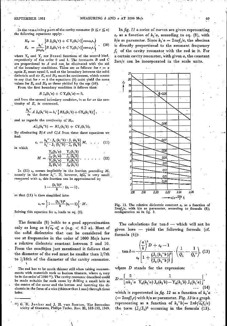
Infig. 11 a series of curves are given representinger as a function of k1'a, according to eq. (8), withbfa as parameter: Since' kj' a = 2nafl/c, the abscissais directly proportional to the resonant frequencyfl of the cavity resonator with the rod in it. Fora certain cavity resonator, with given a, the constant2an/c can be incorporated in the scale units.
2
20
19
18
17
(11)
1L'--..<,<,
~=O.D5
6 ~<,
t~ "I'.. -
3 I'-.. ~~~ ...... r-,11"---. ........ r-, ........ r-,0~7 <,
9 --.... ~r---8~ -............
71'--
6t--- --- ~09 --- r-......--- r--J3!.0 ----~5r--r-- 0,12 --r---t r--I- 0,15 r-----3'à20
2 ..
I
15
12
(12)
216 2.20 2.22 2.21. 2.26_k;a·2~a"
2.18
Fig. Ll , The relative dielectric constant Er as a function of2:naf1jc, with b]« as parameter, according to formula (8);configuration as in fig. 3. .
The calculations for tan <5 - which will not begiven here - yield the following formula (cf.formula (4)):
where D stands for the expression:
[2 . .' 1 J \
D= nkl'a'Yo(kl'a)Jo(kl'b)--:Yo(kl:b) Jo (kl'a) ,(14)
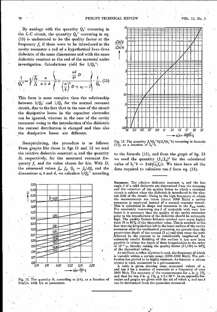
which is represented in fig. 12 as a function of kif a(= 2naf/lc) with bl a as parameter. Fig.13 is a graphrepresenting as a function of k1"b(= 2nby eJl/c)the term (J1/JO)2 occurring in the formula (13).
70 PHILIPS TECHNICAL REVIEW .VOL. 13, No. 3
, By analogy with the quantity Qo' .occurring inthe L-C circuit, the quantity Qo" occurring in eq.(13) is understood to be the quality factor at thefrequency iI if there were to be introduced in thecavity resonator a rod of a hypotheticalloss-freedielectric of the same di~ensions~and with the samedielectric constant as the rod of the material underinvestigation. Calculations yield for I/Qo":
This form is more complex than the relationshipbetween I/Qo' and I/Qo for the normal resonantcircuit, due to the fact that in the case of the circuitthe dissipative losses in the capacitor electrodescan be ignored, whereas in the case of the cavityresonator owing to 'the introduction ofthe dielectricthe current distribution is changed and thus also,the dissipative losses are different.
. Recapitulating, the procedure is as follows:From graphs like those in figs 11 and 12 we readthe relative dielectric constant 8r and the quantityD, respectively, for the measured resonant fre-quency 11 and the value chosen for b]a. With D,the measured values !O, /1' Qo = !o/LJ/o and thedimensions a, band d, we c~lculate I/Q,o" according
0'301r----,-----r--,-----,-----,0,291~--r--~r_---r--~r_--~o
't ~~t=ne~=Q20~l:~l===l=:lW6~-4---+--+_--r-~
o.l~,16 2,20 .2,22 2,24
-k;a=2:°ft2,18 2,26
Fig. 12. The quantity D, according to (14), as a function of2:rmfl/c, with bta as parameter.
10
J{(kib)
J~(kib)
t
5 r.
II
2 V
1/V
V
2 //
1 lL
5,
/2
1/
a
0,010,1 0.3 0,5 0.7 0.9 1.1 1.3 1.5 1.7 19 2,1
-k;b= 21r~vt;t,Fig. 13. The quantity J12(kl"b)fJo2(~"b) occurring in formula(13), as a function of k1"b.
to the formula (15), and from the graph of fig. 13we read the quantity (J1/JO)2 for the calculatedvalue of k1"b = 2nbfi;iI/c. We then have all the
. data required to calculate tan c5 from eq. (13).
Summary. The relative dielectric constant Er and the lossangle 6 of a solid dielectric are determined from the detuningand the reduction of the quality factor to which a resonantcircuit is subject when the dielectric is introduced in the elec-tric field of the circuit. Owing to the high frequency at whichthe measurements are. taken (about 3000 Mc/s) a cavityresonator is employed instead of a normal resonant circuit.This is cylindrical in shape and resonates in the Eo1omode.For accurately measuring tan 6 of materials with very lowlosses it is necessary that the quality of the cavity resonatorprior to the introduetion of the dielectric should be extremelyhigh. The quality factors hitherto reached wère never higherthan 70 to 80% of the theoretical value. This is ascribed to thefact that the irregularities left in the inner surface of the cavityresonator after the mechanical processing are greater than thepenetration depth of the current (1 jJ.) and thus cause the path_followedby the current to be considerably lengthened. By. extremely careful finishing of this surface it has now beenpossible to reduce the depth of these irregularities to the orderof 10-3 jJ., thereby raising the quality factor (17,190) to 98%of the theoretical value.. ,As oscillator a reflex klystron is used, the frequency of which
is variable within a certain range (3090-3260Mc/s). The cali- ,bration has proved to be highly constant. As detector a siliconcrystal is used, connected to a galvanometer.A table is given showing some measured values of Er
and tan 6 for a number of materials at a frequency of over3000 Mc/s. The accuracy of the measurements for Er is ± 1% '.and that for tan 6 is ±. 1% ± 0.2X 10⁻⁴. In an appendix for-mulae and graphs are given with the aid of which Er and tan 6can be determined from the quantities measured.