MEASURING ELECTRICAL ENERGY - kau electrical... · MEASURING ELECTRICAL ENERGY ... The average...
33
1 MEASURING ELECTRICAL ENERGY PRINCIPLES OF MEASUREMENTS ANALOG POWER METERS DIGITAL METERS
Transcript of MEASURING ELECTRICAL ENERGY - kau electrical... · MEASURING ELECTRICAL ENERGY ... The average...

1
MEASURING ELECTRICAL
ENERGY
PRINCIPLES OF MEASUREMENTS
ANALOG POWER METERS
DIGITAL METERS

Electrical Power in Resistive Loads
2
The product of voltage and current, P, varies during the
sinusoidal cycle
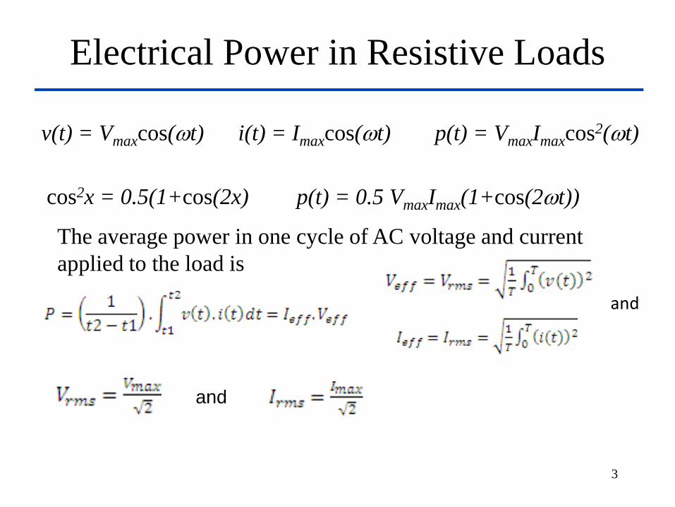
Electrical Power in Resistive Loads
3
v(t) = Vmaxcos(t) i(t) = Imaxcos(t) p(t) = VmaxImaxcos2(t)
cos2x = 0.5(1+cos(2x) p(t) = 0.5 VmaxImax(1+cos(2t))
The average power in one cycle of AC voltage and current
applied to the load is
and
and

Electrical Power in Reactive Loads
4
v(t) = Vmaxcos(t)
i(t) = Imaxcos(t+)
p(t)=VmaxImaxcos(t)cos(t+)

Electrical Power in Reactive Loads
5
i(t) = Imaxcos(t+)
Voltage (V)
Current (A)
Phase angle
(degrees)
p=VmaxImaxcos(t)cos(t+ )
cos(t)cos(t+ )=0.5cos()(1+cos(2t)) – 0.5sin()sin(2t))
P = IrmsVrmscos()
pF = cos( ) real average power
divided by apparent power, pF = P/VA
Active power (W)
Apparent power
(VA) Reactive power
(VARs)
The maximum is called the
apparent power or volt-ampere (VA)

Monitoring voltage, current, and power
6
The apparent power (VA) is the one generated and transmitted to
the loads. Two parts:
•one converted to real work, expressed in watts and
•one stored in the electromagnetic fields; called the reactive
power expressed in reactive Volt-Amperes (VARs).
How
much is
pF and
VAR?
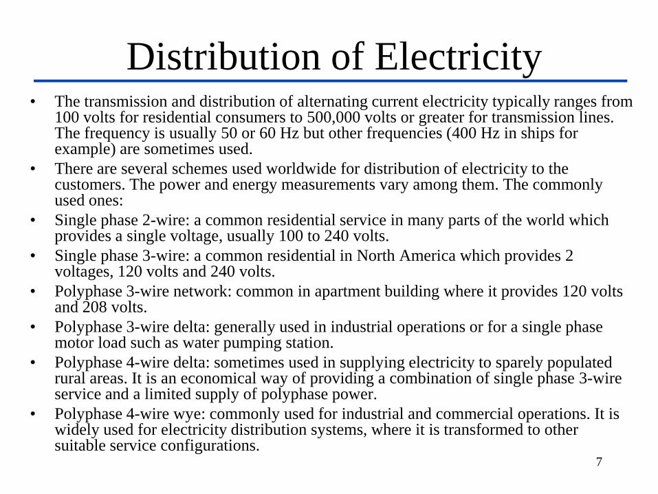
Distribution of Electricity • The transmission and distribution of alternating current electricity typically ranges from
100 volts for residential consumers to 500,000 volts or greater for transmission lines. The frequency is usually 50 or 60 Hz but other frequencies (400 Hz in ships for example) are sometimes used.
• There are several schemes used worldwide for distribution of electricity to the customers. The power and energy measurements vary among them. The commonly used ones:
• Single phase 2-wire: a common residential service in many parts of the world which provides a single voltage, usually 100 to 240 volts.
• Single phase 3-wire: a common residential in North America which provides 2 voltages, 120 volts and 240 volts.
• Polyphase 3-wire network: common in apartment building where it provides 120 volts and 208 volts.
• Polyphase 3-wire delta: generally used in industrial operations or for a single phase motor load such as water pumping station.
• Polyphase 4-wire delta: sometimes used in supplying electricity to sparely populated rural areas. It is an economical way of providing a combination of single phase 3-wire service and a limited supply of polyphase power.
• Polyphase 4-wire wye: commonly used for industrial and commercial operations. It is widely used for electricity distribution systems, where it is transformed to other suitable service configurations.
7

Metering Electricity
• Active power, reactive power and volt-ampere are commonly measured
• Maximum or peak power is used to determine the capacity of the generator and transmission system.
• Average power taken by the load in a given time interval indicates the power demand. – Watt (W) meter: measures active electrical power, normally displayed as kW.
– Reactive Volt-Ampere (VAR) meter: measures reactive electrical power, normally displayed as kVAR.
– Volt-Ampere (VA) meter: measures apparent electrical power, normally displayed as kVA.
• Energy is measured by energy meters and generally used for billing – Watt hour (Wh)meter: measures active electrical energy, integrating active
electrical power with respect to time; watts x time(in hours), normally displayed as kWh.
– VAR hour (VARh) meter: measures reactive electrical energy, integrating reactive electrical power with respect to time, normally displayed as kVARh.
– VA hour (VAh) meter: measures apparent electrical energy, integrating apparent electrical power with respect to time, normally displayed as kVAh.
8
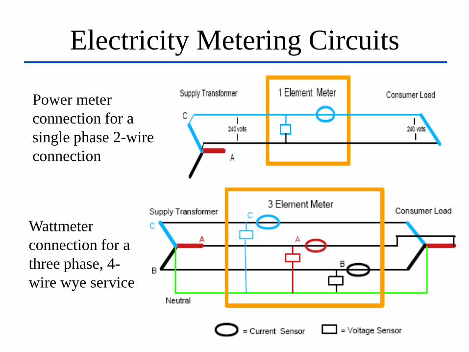
Electricity Metering Circuits
9
Power meter
connection for a
single phase 2-wire
connection
Wattmeter
connection for a
three phase, 4-
wire wye service
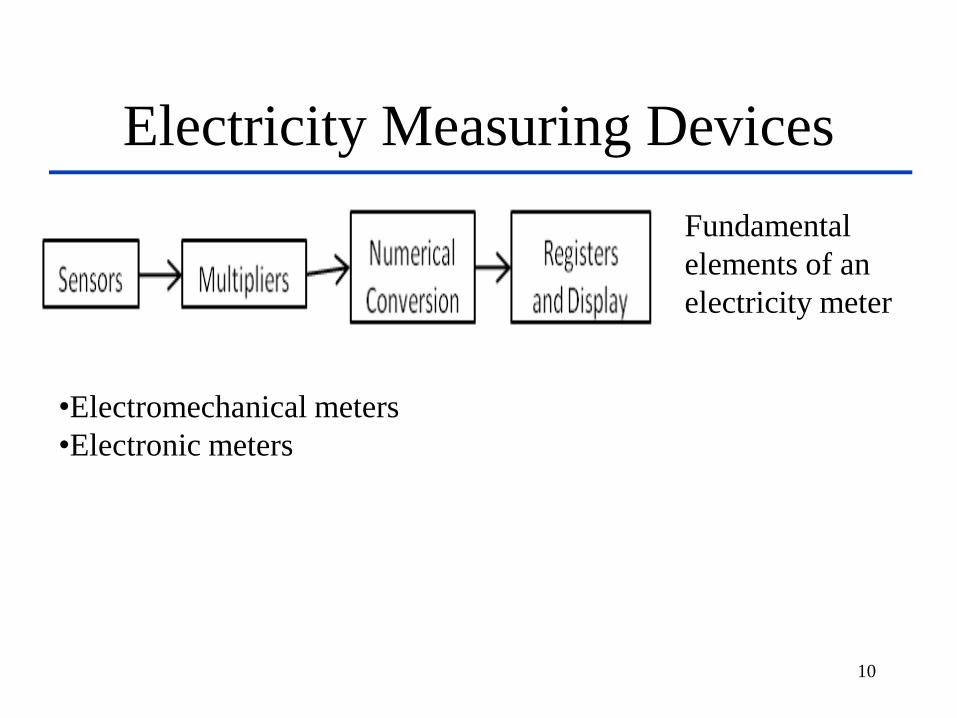
Electricity Measuring Devices
10
Fundamental
elements of an
electricity meter
•Electromechanical meters
•Electronic meters

Electromechanical meters
11
1. Current coil
2. Voltage coil
Mechanical Watt-hours meter
Mechanical means for measuring Watt-Hours are usually centered around the concept of the motor:
1. build an AC motor that spins at a rate of speed proportional to the instantaneous power in a circuit, then have that motor turn an “odometer” style counting mechanism to keep a running total of energy consumed.
2. The “motor” used in these meters has a rotor made of a thin aluminum disk, with the rotating magnetic field established by sets of coils energized by line voltage and load current so that the rotational speed of the disk is dependent on both voltage and current.
12

13
1. Voltage coil - many turns
of fine wire encased in
plastic, connected in
parallel with load.
2. Current coil - three turns
of thick wire, connected
in series with load.
3. Stator - concentrates and
confines magnetic field.
4. Aluminium rotor disc.
5. rotor brake magnets.
6. spindle with worm gear.
7. display dials - note that
the 1/10, 10 and 1000
dials rotate clockwise
while the 1, 100 and
10000 dials rotate
counter-clockwise
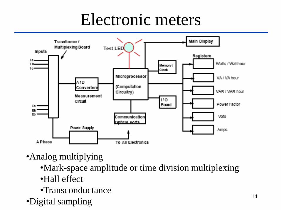
Electronic meters
14
•Analog multiplying
•Mark-space amplitude or time division multiplexing
•Hall effect
•Transconductance
•Digital sampling
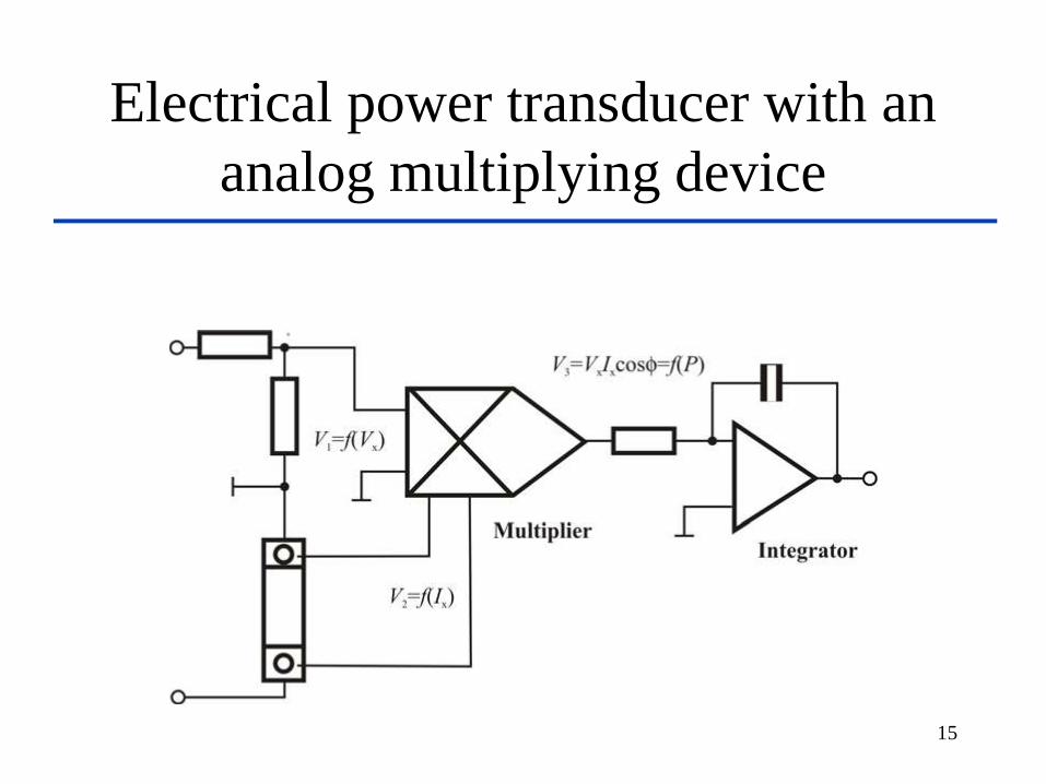
Electrical power transducer with an
analog multiplying device
15

Time Division Multiplexer (TDM)
Transducer
16

Time Division Multiplexing(TDM)
17
V2 = k2I
T1 – T2 = k1V1
The average value of V2 is V2A = k2I(T1-T2)/(T1+T2) = k1k2IV/(T1+T2)
Power to DC voltage converter using pulse-width pulse-height multiplier

18
Waveforms for
Analog
computation type
wattmeter (TDM)

General features of TDM method
• Good cost to accuracy ratio
• Excellent linearity and reliability
• Performance under distortion is limited
• Direct measurement limited to watts / vars
• Calibration is necessary
19
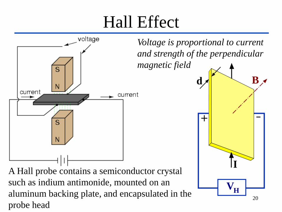
Hall Effect
20
Voltage is proportional to current
and strength of the perpendicular
magnetic field
A Hall probe contains a semiconductor crystal
such as indium antimonide, mounted on an
aluminum backing plate, and encapsulated in the
probe head

Hall effect sensors in measuring
electrical power
21
Hall effect power sensor measures instantaneous power
vH(t) =RHi(t)B(t) RH = Hall constant, vx(t) = ai(t) and ix(t) = bB(t)

Advantages of Hall effect method
• Analog watt transducers including Hall effect provide good accuracy even with distorted wave shapes, discontinuity, or where there is poor frequency regulation.
• General features of this method can be summarized as – Very cost effective
technology
– Can measure Watt /VARs, but not VA
– Linearity less than TDM technology
– Excellent response for harmonic content
– Susceptible to large temperature changes. 22
Bias
Resistor
Hal
l S
enso
r
Integration/
calibration Register
Module
Indicator
LED
Magnetic
Core
Iline
Vline

Transconductance
23
I0
GT(V2 – V1)
V1
V2
G0 Rd
Having Vi = (V1 – V2)
•An ordinary transistor type differential amplifier can also work:
•The secondary current from the meter transformer is converted to a voltage and
applied the bases of the two transistors.
•The line voltage is applied between the collectors and emitters of the transistors.
•A potential difference between the two collectors is generated. This voltage is the
product of the line voltage and line currents and therefore proportional to the line
power.
•Excellent cost to accuracy ratio
•Requires four quadrant amplifier for superior performance under varying power factors
and harmonic distortions.
CA 3080

Digital sampling
24
u(t): instantaneous
voltage value at time t
i (t) instantaneous
current value at time t
u (k): instantaneous
voltage value at kth
sample
i (k) instantaneous
current value at kth
sample
T : cycle

Waveforms for digital sampling
25
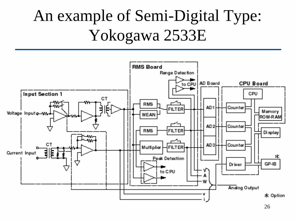
An example of Semi-Digital Type:
Yokogawa 2533E
26

An example of a Full-Digital
Type: Yokogawa WT 2030
27

Review of Digital Sampling
• Only technology that does not use analog values of voltage and current. – analog values of voltage and currents are converted to digital data prior to
any multiplication taking place.
– A group of sample includes a sample of voltage and current on each of the three lines.
– Two consecutive cycles have samples that are 34 microseconds apart, this is called sample migration and ensures that each group of samples is not taken at an identical point during the cycling of the signal.
• Most inaccuracies can be fully compensated algorithmically eliminating the need for any physical calibration of the meter.
• Not very cost effective technology for single phase residential compared to TDM, Hall effect and transconductance technologies.
• When measured with digital sampling type instrumentation, the powerful micro-processors can run statistical routines to reveal computed data, oriented to particular customer requirements.
28
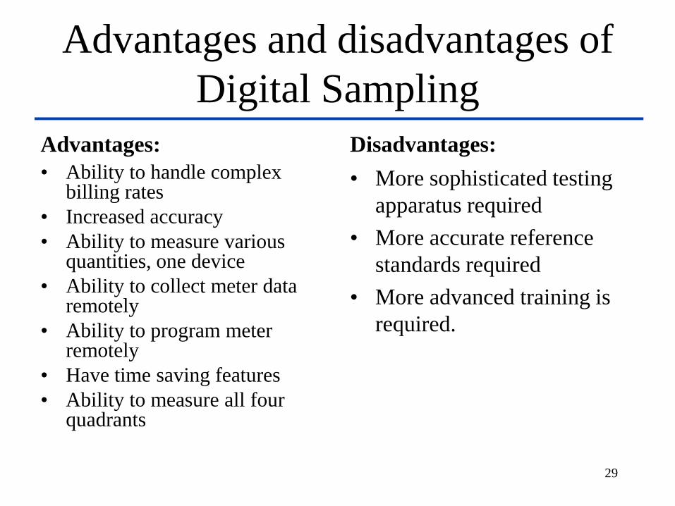
Advantages and disadvantages of
Digital Sampling
Advantages:
• Ability to handle complex billing rates
• Increased accuracy
• Ability to measure various quantities, one device
• Ability to collect meter data remotely
• Ability to program meter remotely
• Have time saving features
• Ability to measure all four quadrants
Disadvantages:
• More sophisticated testing
apparatus required
• More accurate reference
standards required
• More advanced training is
required.
29

30

31

32
33