
MCP19111 PMBus™ POL Reference Design User's Guide · Tempe, Arizona; Gresham, Oregon and ......
44
2015 Microchip Technology Inc. DS50002379A MCP19111 PMBus™ Protocol-Enabled Point-of-Load (POL) Converter Reference Design User’s Guide
Transcript of MCP19111 PMBus™ POL Reference Design User's Guide · Tempe, Arizona; Gresham, Oregon and ......

2015 Microchip Technology Inc. DS50002379A
MCP19111PMBus™ Protocol-Enabled
Point-of-Load (POL) ConverterReference Design
User’s Guide

DS50002379A-page 2 2015 Microchip Technology Inc.
Information contained in this publication regarding deviceapplications and the like is provided only for your convenienceand may be superseded by updates. It is your responsibility toensure that your application meets with your specifications.MICROCHIP MAKES NO REPRESENTATIONS ORWARRANTIES OF ANY KIND WHETHER EXPRESS ORIMPLIED, WRITTEN OR ORAL, STATUTORY OROTHERWISE, RELATED TO THE INFORMATION,INCLUDING BUT NOT LIMITED TO ITS CONDITION,QUALITY, PERFORMANCE, MERCHANTABILITY ORFITNESS FOR PURPOSE. Microchip disclaims all liabilityarising from this information and its use. Use of Microchipdevices in life support and/or safety applications is entirely atthe buyer’s risk, and the buyer agrees to defend, indemnify andhold harmless Microchip from any and all damages, claims,suits, or expenses resulting from such use. No licenses areconveyed, implicitly or otherwise, under any Microchipintellectual property rights unless otherwise stated.
Note the following details of the code protection feature on Microchip devices:
• Microchip products meet the specification contained in their particular Microchip Data Sheet.
• Microchip believes that its family of products is one of the most secure families of its kind on the market today, when used in the intended manner and under normal conditions.
• There are dishonest and possibly illegal methods used to breach the code protection feature. All of these methods, to our knowledge, require using the Microchip products in a manner outside the operating specifications contained in Microchip’s Data Sheets. Most likely, the person doing so is engaged in theft of intellectual property.
• Microchip is willing to work with the customer who is concerned about the integrity of their code.
• Neither Microchip nor any other semiconductor manufacturer can guarantee the security of their code. Code protection does not mean that we are guaranteeing the product as “unbreakable.”
Code protection is constantly evolving. We at Microchip are committed to continuously improving the code protection features of ourproducts. Attempts to break Microchip’s code protection feature may be a violation of the Digital Millennium Copyright Act. If such actsallow unauthorized access to your software or other copyrighted work, you may have a right to sue for relief under that Act.
Microchip received ISO/TS-16949:2009 certification for its worldwide headquarters, design and wafer fabrication facilities in Chandler and Tempe, Arizona; Gresham, Oregon and design centers in California and India. The Company’s quality system processes and procedures are for its PIC® MCUs and dsPIC® DSCs, KEELOQ® code hopping devices, Serial EEPROMs, microperipherals, nonvolatile memory and analog products. In addition, Microchip’s quality system for the design and manufacture of development systems is ISO 9001:2000 certified.
QUALITY MANAGEMENT SYSTEM CERTIFIED BY DNV
== ISO/TS 16949 ==
Trademarks
The Microchip name and logo, the Microchip logo, dsPIC, FlashFlex, flexPWR, JukeBlox, KEELOQ, KEELOQ logo, Kleer, LANCheck, MediaLB, MOST, MOST logo, MPLAB, OptoLyzer, PIC, PICSTART, PIC32 logo, RightTouch, SpyNIC, SST, SST Logo, SuperFlash and UNI/O are registered trademarks of Microchip Technology Incorporated in the U.S.A. and other countries.
The Embedded Control Solutions Company and mTouch are registered trademarks of Microchip Technology Incorporated in the U.S.A.
Analog-for-the-Digital Age, BodyCom, chipKIT, chipKIT logo, CodeGuard, dsPICDEM, dsPICDEM.net, ECAN, In-Circuit Serial Programming, ICSP, Inter-Chip Connectivity, KleerNet, KleerNet logo, MiWi, MPASM, MPF, MPLAB Certified logo, MPLIB, MPLINK, MultiTRAK, NetDetach, Omniscient Code Generation, PICDEM, PICDEM.net, PICtail, RightTouch logo, REAL ICE, SQI, Serial Quad I/O, Total Endurance, TSHARC, USBCheck, VariSense, ViewSpan, WiperLock, Wireless DNA, and ZENA are trademarks of Microchip Technology Incorporated in the U.S.A. and other countries.
SQTP is a service mark of Microchip Technology Incorporated in the U.S.A.
Silicon Storage Technology is a registered trademark of Microchip Technology Inc. in other countries.
GestIC is a registered trademarks of Microchip Technology Germany II GmbH & Co. KG, a subsidiary of Microchip Technology Inc., in other countries.
All other trademarks mentioned herein are property of their respective companies.
© 2015, Microchip Technology Incorporated, Printed in the U.S.A., All Rights Reserved.
ISBN: 978-1-63277-476-7

Object of Declaration: MCP19111 PMBus™ Protocol-Enabled POL Converter Reference Design
2015 Microchip Technology Inc. DS50002379A-page 3

MCP19111 PMBus™ Protocol-Enabled POL Converter Reference Design
NOTES:
DS50002379A-page 4 2015 Microchip Technology Inc.

MCP19111 PMBus™PROTOCOL-ENABLED POL
CONVERTER REFERENCE DESIGN
USER’S GUIDETable of Contents
Preface ........................................................................................................................... 7Introduction............................................................................................................ 7
Document Layout .................................................................................................. 8
Conventions Used in this Guide ............................................................................ 9
Warranty Registration.......................................................................................... 10
Recommended Reading...................................................................................... 10
The Microchip Web Site ...................................................................................... 10
Development Systems Customer Change Notification Service .......................... 11
Customer Support ............................................................................................... 11
MCP19111 PMBus™-Enabled POL Converter Reference Design License........ 11
Revision History .................................................................................................. 11
Chapter 1. Product Overview1.1 Introduction ................................................................................................... 131.2 MCP19111 Device Short Overview .............................................................. 131.3 What is the MCP19111 PMBus™ Protocol-Enabled Point-of-Load
Converter Reference Design? ................................................................ 15
1.4 System Requirements .................................................................................. 151.4.1 The Development System’s Components ................................................. 16
1.5 What the MCP19111 PMBus™ Protocol-Enabled Point-of-Load Converter Reference Design Kit Contains? ............................................................ 16
Chapter 2. Installation and Operation2.1 Board Features ............................................................................................. 172.2 Getting Started ............................................................................................. 18
2.2.1 Necessary Instruments and Tools ............................................................. 182.2.2 Setup Procedure ....................................................................................... 182.2.3 Board Testing ............................................................................................ 19
Chapter 3. Calibration Procedure3.1 Introduction ................................................................................................... 213.2 Voltage Calibration ....................................................................................... 223.3 Current Calibration with Inductor Temperature Measurement ..................... 23
Chapter 4. Typical Performance Data, Curves and Waveforms .............................. 25
2015 Microchip Technology Inc. DS50002379A-page 5
MCP19111 PMBus™ Protocol-Enabled POL Converter Reference Design
Appendix A. Schematics and LayoutsA.1 Introduction .................................................................................................. 33A.2 Board – Schematic 1 .................................................................................... 34A.3 Board – Schematic 2 .................................................................................... 35A.4 Board – Top Layer ....................................................................................... 36A.5 Board – Top Copper .................................................................................... 36A.6 Board – Mid Layer 1 ..................................................................................... 37A.7 Board – Mid Layer 2 ..................................................................................... 37A.8 Board – Bottom Layer .................................................................................. 38A.9 Board – Bottom Copper ............................................................................... 38
Appendix B. Bill of Materials (BOM) ...........................................................................39
Appendix C. Calibration ExampleC.1 Introduction .................................................................................................. 41C.2 Configuration Requirements ........................................................................ 42
C.2.1 Calibration .................................................................................................42
Worldwide Sales and Service .....................................................................................44
DS50002379A-page 6 2015 Microchip Technology Inc.

MCP19111 PMBus™PROTOCOL-ENABLED POL
CONVERTER REFERENCE DESIGNUSER’S GUIDE
Preface
INTRODUCTION
This chapter contains general information that will be useful to know before using the MCP19111 PMBus™ Protocol-Enabled Point-of-Load Converter Reference Design. Items discussed in this chapter include:
• Document Layout
• Conventions Used in this Guide
• Warranty Registration
• Recommended Reading
• The Microchip Web Site
• Development Systems Customer Change Notification Service
• Customer Support
• Revision HistoryI
NOTICE TO CUSTOMERS
All documentation becomes dated, and this manual is no exception. Microchip tools and documentation are constantly evolving to meet customer needs, so some actual dialogs and/or tool descriptions may differ from those in this document. Please refer to our web site (www.microchip.com) to obtain the latest documentation available.
Documents are identified with a “DS” number. This number is located on the bottom of each page, in front of the page number. The numbering convention for the DS number is “DSXXXXXXXXA”, where “XXXXXXXX” is the document number and “A” is the revision level of the document.
For the most up-to-date information on development tools, see the MPLAB® IDE online help. Select the Help menu, and then Topics to open a list of available online help files.
WARNING
The present reference design is intended to be used only to prove the MCP19111 functionality and performance, solely in a laboratory environment. Microchip Technology Inc. assumes no liability for any damage resulting from using the present reference design in other purposes.
2015 Microchip Technology Inc. DS50002379A-page 7

MCP19111 PMBus™ Protocol-Enabled POL Converter Reference Design
DOCUMENT LAYOUT
This document describes how to use the MCP19111 PMBus™ Protocol-Enabled Point-of-Load Converter Reference Design as a development tool to emulate and debug firmware on a target board, as well as how to program devices. The document is organized as follows:
• Chapter 1. “Product Overview” – Important information about the MCP19111 PMBus™ Protocol-Enabled Point-of-Load Converter Reference Design.
• Chapter 2. “Installation and Operation” – Includes instructions on how to get started using the MCP19111 PMBus™ Protocol-Enabled Point-of-Load Converter Reference Design.
• Chapter 3. “Calibration Procedure” – Includes instructions on the calibration procedure of the MCP19111 PMBus™ Protocol-Enabled Point-of-Load Converter Reference Design.
• Chapter 4. “Typical Performance Data, Curves and Waveforms” – Includes typical performance graphs of data, curves and waveforms.
• Appendix A. “Schematics and Layouts” – Shows the schematic and layout diagrams for the MCP19111 PMBus™ Protocol-Enabled Point-of-Load Converter Reference Design.
• Appendix B. “Bill of Materials (BOM)” – Lists the parts used to build the MCP19111 PMBus™ Protocol-Enabled Point-of-Load Converter Reference Design.
• Appendix C. “Calibration Example” – Gives an example of a calibration procedure for the MCP19111 PMBus™ Protocol-Enabled Point-of-Load Converter Reference Design.
DS50002379A-page 8 2015 Microchip Technology Inc.

Preface
CONVENTIONS USED IN THIS GUIDE
This manual uses the following documentation conventions:
DOCUMENTATION CONVENTIONS
Description Represents Examples
Arial font:
Italic characters Referenced books MPLAB® IDE User’s Guide
Emphasized text ...is the only compiler...
Initial caps A window the Output window
A dialog the Settings dialog
A menu selection select Enable Programmer
Quotes A field name in a window or dialog
“Save project before build”
Underlined, italic text with right angle bracket
A menu path File>Save
Bold characters A dialog button Click OK
A tab Click the Power tab
N‘Rnnnn A number in verilog format, where N is the total number of digits, R is the radix and n is a digit.
4‘b0010, 2‘hF1
Text in angle brackets < > A key on the keyboard Press <Enter>, <F1>
Courier New font:
Plain Courier New Sample source code #define START
Filenames autoexec.bat
File paths c:\mcc18\h
Keywords _asm, _endasm, static
Command-line options -Opa+, -Opa-
Bit values 0, 1
Constants 0xFF, ‘A’
Italic Courier New A variable argument file.o, where file can be any valid filename
Square brackets [ ] Optional arguments mcc18 [options] file [options]
Curly brackets and pipe character: { | }
Choice of mutually exclusive arguments; an OR selection
errorlevel {0|1}
Ellipses... Replaces repeated text var_name [, var_name...]
Represents code supplied by user
void main (void){ ...}
2015 Microchip Technology Inc. DS50002379A-page 9

MCP19111 PMBus™ Protocol-Enabled POL Converter Reference Design
WARRANTY REGISTRATION
Please complete the enclosed Warranty Registration Card and mail it promptly. Sending in the Warranty Registration Card entitles users to receive new product updates. Interim software releases are available at the Microchip web site.
RECOMMENDED READING
This user’s guide describes how to use MCP19111 PMBus™ Protocol-Enabled Point-of-Load Converter Reference Design. Other useful documents are listed below. The following Microchip documents are available and recommended as supplemental reference resources.
MCP19110/11 Data Sheet (DS20002331)
This data sheet describes the operation and features of the MCP19110/11 digitally-enhanced power analog controller with integrated synchronous driver.
PMBus™ Monitoring Graphical User Interface User’s Guide (DS50002380)
This user’s guide describes how to use the PMBus Monitoring Graphical User Interface (GUI).
TB3139, MCP19111 PMBus™ Firmware Technical Brief (DS90003139)
This technical brief describes how to use the MCP19111 PMBus firmware.
THE MICROCHIP WEB SITE
Microchip provides online support via our web site at www.microchip.com. This web site is used as a means to make files and information easily available to customers. Accessible by using your favorite Internet browser, the web site contains the following information:
• Product Support – Data sheets and errata, application notes and sample programs, design resources, user’s guides and hardware support documents, latest software releases and archived software
• General Technical Support – Frequently Asked Questions (FAQs), technical support requests, online discussion groups, Microchip consultant program member listing
• Business of Microchip – Product selector and ordering guides, latest Microchip press releases, listing of seminars and events, listings of Microchip sales offices, distributors and factory representatives
DS50002379A-page 10 2015 Microchip Technology Inc.

Preface
DEVELOPMENT SYSTEMS CUSTOMER CHANGE NOTIFICATION SERVICE
Microchip’s customer notification service helps keep customers current on Microchip products. Subscribers will receive e-mail notification whenever there are changes, updates, revisions or errata related to a specified product family or development tool of interest.
To register, access the Microchip web site at www.microchip.com, click on Customer Change Notification and follow the registration instructions.
The Development Systems product group categories are:
• Compilers – The latest information on Microchip C compilers, assemblers, linkers and other language tools. These include all MPLAB® C compilers; all MPLAB assemblers (including MPASM™ Assembler); all MPLAB linkers (including MPLINK™ Object Linker); and all MPLAB librarians (including MPLIB™ Object Librarian).
• Emulators – The latest information on Microchip in-circuit emulators.This includes the MPLAB REAL ICE™ and MPLAB ICE 2000 In-Circuit Emulators.
• In-Circuit Debuggers – The latest information on the Microchip in-circuit debuggers. This includes MPLAB ICD 3 In-Circuit debugger and PICkit™ 3 Debug Express.
• MPLAB® IDE – The latest information on Microchip MPLAB IDE, the Windows® Integrated Development Environment for development systems tools. This list is focused on the MPLAB IDE, MPLAB IDE Project Manager, MPLAB Editor and MPLAB SIM Simulator, as well as general editing and debugging features.
• Programmers – The latest information on Microchip programmers. These include production programmers, such as MPLAB REAL ICE In-Circuit Emulator, MPLAB ICD 3 In-Circuit Debugger and MPLAB PM3 Device Programmer.
CUSTOMER SUPPORT
Users of Microchip products can receive assistance through several channels:
• Distributor or Representative
• Local Sales Office
• Field Application Engineer (FAE)
• Technical Support
Customers should contact their distributor, representative or field application engineer (FAE) for support. Local sales offices are also available to help customers. A listing of sales offices and locations is included in the back of this document.
Technical support is available through the web site at:
http://www.microchip.com/support
MCP19111 PMBUS-ENABLED POL CONVERTER REFERENCE DESIGN LICENSE
Copyright © 2015 Microchip Technology Inc. All rights reserved.
1. License Grant. Microchip licenses to you the right to use this reference design and all related documentation (“Reference Design Materials”) for purposes of developing your application using Microchip products. You may not re-distribute Reference Design Materials to any third parties.
2. Warranty Disclaimer. Reference Design Materials are provided for your conve-nience only and may be superseded by updates. These materials will not be deemed to modify Microchip’s standard warranty for its products. It is your responsibility to: (1) ensure that the Reference Design Materials, and your use thereof, meet your requirements; and (2) test your application.
2015 Microchip Technology Inc. DS50002379A-page 11

MCP19111 PMBus™ Protocol-Enabled POL Converter Reference Design
REFERENCE DESIGN MATERIALS ARE PROVIDED “AS IS” WITHOUT WARRANTY OF ANY KIND, EITHER EXPRESS OR IMPLIED, INCLUDING WITHOUT LIMITATION, ANY WARRANTY OF MERCHANTABILITY, TITLE, NON-INFRINGEMENT AND FITNESS FOR A PARTICULAR PURPOSE.
3. Limit on Liability. IN NO EVENT WILL MICROCHIP BE LIABLE OR OBLIGATED UNDER CONTRACT, NEGLIGENCE, STRICT LIABILITY, CONTRIBUTION, BREACH OF WARRANTY, OR OTHER LEGAL EQUITABLE THEORY ANY DIRECT OR INDIRECT DAMAGES OR EXPENSES INCLUDING BUT NOT LIMITED TO ANY INCIDENTAL, SPECIAL, OR CONSEQUENTIAL DAMAGES, LOST PROFITS OR LOST DATA, COST OF PROCUREMENT OF SUBSTITUTE GOODS, TECHNOLOGY, SERVICES, ANY CLAIMS BY THIRD PARTIES (INCLUDING BUT NOT LIMITED TO ANY DEFENSE THEREOF), OR OTHER SIMILAR COSTS. MICROCHIP DISCLAIMS ALL LIABILITY ARISING FROM THIS INFORMATION AND ITS USE. USE OF MICROCHIP DEVICES IN LIFE SUPPORT AND/OR SAFETY APPLICATIONS IS ENTIRELY AT THE BUYER’S RISK, AND THE BUYER AGREES TO DEFEND, INDEMNIFY AND HOLD HARMLESS MICROCHIP FROM ANY AND ALL DAMAGES, CLAIMS, SUITS, OR EXPENSES RESULTING FROM SUCH USE.
TO THE FULLEST EXTENT PERMITTED BY LAW, MICROCHIP’S LIABILITY IS CAPPED AT THE AMOUNT YOU PAID DIRECTLY TO MICROCHIP FOR THESE REFRENCE DESIGN MATERIALS.
4. Governing Law. THIS LICENSE WILL BE GOVERNED BY AND CONSTRUCTED UNDER THE LAWS OF THE STATE OF ARIZONA AND THE UNITED STATES WITHOUT REGARD TO CONFLICTS OF LAWS PROVISIONS. Licensee agrees that any disputes arising out of or related to this License, Software or Reference Design Materials will be brought in the courts of State of Arizona. The parties agree to waive their rights to a jury trial in actions relating to this License.
REVISION HISTORY
Revision A (June 2015)
This is the initial release of this document.
DS50002379A-page 12 2015 Microchip Technology Inc.

MCP19111 PMBus™PROTOCOL-ENABLED POL
CONVERTER REFERENCE DESIGNUSER’S GUIDE
Chapter 1. Product Overview
1.1 INTRODUCTION
This chapter provides an overview of the MCP19111 PMBus™ Protocol-Enabled Point-of-Load Converter Reference Design and covers the following topics:
• MCP19111 Device Short Overview
• What is the MCP19111 PMBus™ Protocol-Enabled Point-of-Load Converter Reference Design?
• What the MCP19111 PMBus™ Protocol-Enabled Point-of-Load Converter Reference Design Kit Contains?
1.2 MCP19111 DEVICE SHORT OVERVIEW
The MCP19111 device is a highly integrated, mixed signal, Analog Pulse-Width Modulation (PWM) Current mode controller with an integrated microcontroller core for synchronous DC/DC step-down applications. Since the MCP19111 uses traditional analog control circuitry to regulate the output of the DC/DC converter, the integration of the PIC® microcontroller mid-range core is used to provide complete customization of the device operating parameters, start-up and shutdown profiles, protection levels and Fault handling procedures.
The MCP19111 is designed to efficiently operate from a single, 4.5V to 32V supply. It features integrated synchronous drivers, a bootstrap device, internal linear regulator and 4000 words of nonvolatile memory, all in a space-saving, 28-pin 5 mm x 5 mm QFN package.
PMBus™ or I2C™ can be used by a host to communicate with, or modify the operation of, the MCP19111. A subset of the commands contained in the “PMBus™ Power System Management Protocol Specification, Revision 1.1” are supported by the ARD00609 board.
An internal 5V rail provides power to the PIC MCU and is also present on the VDD pin.
It is recommended that a 1 μF capacitor be placed between VDD and PGND. The VDD pin may also be directly connected to the VDR pin or connected through a low-pass RC filter. The VDR pin provides power to the internal synchronous driver.
NOTICE TO CUSTOMERS
The present reference design is intended to be used only to prove the MCP19111 functionality and performance, solely in laboratory environment. Microchip Technology Inc. assumes no liability for any damage resulting from using the present reference design in other purposes.
CAUTION
All the functionalities described in this document are specific to the original firmware loaded in the MCP19111. Once the user software is loaded, the PMBus communication and board settings become the user’s responsibility.
2015 Microchip Technology Inc. DS50002379A-page 13

MC
P19111 P
MB
us™
Pro
toco
l-En
abled
PO
L C
on
verter Referen
ce Desig
n
DS
50
00
23
79
A-p
ag
e 1
4
20
15
Micro
chip
Te
chn
olo
gy In
c.
+VOUT
-VOUT
FIGURE 1-1: MCP19111 Typical Application.
HDRV
BOOT
PHASE
LDRV
VIN
VDD
VDR
+ISEN
-ISEN
+VSEN
-VSEN
GND
PGND
GPB0
GPA7
GPA4
GPA1
GPB6
GPB7
GPA3
GPB2
GPA2
GPA5
GPB4
GPB5
GPA0
GPB1
GPA6
MCLR
ICDCLK
ICDDAT
SDA
SCL
SMBus
SYNC
ADDR0
ADDR1
CNTL
PGOOD
TRACK
MCP19111
VIN
X I CDProgrammer
MPLAB®
™Alert

Product Overview
1.3 WHAT IS THE MCP19111 PMBus™ PROTOCOL-ENABLED POINT-OF-LOAD CONVERTER REFERENCE DESIGN?
The MCP19111 PMBus™ Protocol-Enabled Point-of-Load Converter Reference Design demonstrates how the MCP19111 device operates in a synchronous buck topology over a wide input voltage and load range. Nearly all operational and control system parameters are programmable by utilizing the integrated PIC microcontroller.
For precise measurements of the output current, a precision op amp (MCP6061) and an inductor temperature sensor (MCP9700) are provided. The output current may be measured and calibrated using an internal or external op amp. The temperature compensation may be performed by temperature measurement or by second order polynomial approximation.
The PMBus Monitoring Graphical User Interface (GUI) can be used to program the functioning parameters and to check the operational status. To simplify the connection, a USB to PMBus converter is implemented on board, allowing a standard interface to any Windows® computer.
Alternatively, the user can program the MCP19111 using self-developed firmware (see Section 1.4.1 “The Development System’s Components”), tailoring it to the application.
The evaluation board contains headers for In-Circuit Serial Programming™ (ICSP™) as well as I2C and mini-USB communication, pull-up and pull-down resistor pads and test point pads on each GPIO pin, and a push button for system development. The MCP19111 PMBus™ Protocol-Enabled Point-of-Load Converter Reference Design is also intended to demonstrate an optimized Printed Circuit Board (PCB) layout that minimizes parasitics, while increasing efficiency and power density.
Proper PCB layout is critical to achieve optimum MCP19111 operation, as well as power train efficiency and noise minimization.
1.4 SYSTEM REQUIREMENTS
To operate the board, the following tools are required:
• Microsoft® .NET Framework 4.5 or higher
• PMBus Monitoring Graphical User Interface: This graphical user interface allows monitoring and changing input and output parameters for any device that has an incorporated PMBus™ protocol. For installation, operation and other system requirements, see the “PMBus™ Monitoring Graphical User Interface User’s Guide” (DS50002380).
WARNING
Any changes in the Settings tab from the Developer menu may result in system instability and/or permanent damage of the board, and is the user’s sole responsibility to take the necessary precautions.
2015 Microchip Technology Inc. DS50002379A-page 15

MCP19111 PMBus™ Protocol-Enabled POL Converter Reference Design
1.4.1 The Development System’s Components
To redevelop the board firmware, the following may be required:
• MCP19111 MPLAB® X IDE Graphical User Interface Plug-In: This graphical user interface simplifies the configuration of the MCP19111. It is user-installed and resides within the MPLAB X IDE. The “MCP19110/11/18/19 – Buck Power Supply Graphical User Interface User’s Guide” (DS50002113) describes the plug-in installation procedure, as well as how to use it.
• MPLAB® X Integrated Development Environment (IDE): This is a complete software development environment that links the software and hardware development. This is a free tool, available from Microchip, that supports device configuration, advanced programming, as well as debug support. The GUI resides inside the MPLAB X IDE.
• MPLAB® XC8 Compiler: The firmware described above is coded in C and thus requires a C compiler. C compilers are available for free from Microchip’s web site.
• Configuration tools:
- PICkit™ Serial Analyzer: This communication tool may be used to configure the evaluation board. The PICkit Serial Analyzer is recommended and is available for purchase on microchipDIRECT.
- PICkit 3 In-Circuit Debugger/Programmer: A programming tool is required to reprogram the evaluation board. The PICkit 3 or MPLAB ICD 3 is recommended and they are available for purchase on microchipDIRECT.
- Any other user-preferred I2C connection for further board development.
To resume the original functionality of the ARD00609, the user can download the 00609_RevA1.hex file from Microchip’s web site and upload it in the MCP19111 using a PICkit 3 In-Circuit Debugger/Programmer.
1.5 WHAT THE MCP19111 PMBus™ PROTOCOL-ENABLED POINT-OF-LOAD CONVERTER REFERENCE DESIGN KIT CONTAINS?
This MCP19111 PMBus™ Protocol-Enabled Point-of-Load Converter Reference Design kit includes the following items:
• MCP19111 PMBus™ Protocol-Enabled Point-of-Load Converter Reference Design board (ARD00609)
• Important Information Sheet
DS50002379A-page 16 2015 Microchip Technology Inc.

MCP19111 PMBus™PROTOCOL-ENABLED POL
CONVERTER REFERENCE DESIGN
USER’S GUIDEChapter 2. Installation and Operation
2.1 BOARD FEATURES
The MCP19111 PMBus™ Protocol-Enabled Point-of-Load Converter Reference Design was developed to provide a compact, low-cost and highly efficient step-down conversion for low-to-medium output currents.
The key features of this board include:
• Input Voltage Range: 8V to 14V
• Output Voltage: 1.2V (can be adjusted by software from 0.1 to 3.6V)
• Maximum Output Current: 20A
• 88% Typical Efficiency at 1.2V/15A output and 12V input
• 500 kHz Switching Frequency (can be software adjusted from 100 kHz to 1.6 MHz)
• On-Board High-Performance Power MOSFET Transistors
• Overcurrent and Overtemperature Protection
• Status Report (including errors, input voltage, output voltage and current) via the PMBus Communication Protocol
• Precision Op Amp for Accurate Output Current Measurement
• Inductor Temperature Sensor
• Calibration of Output Voltage
• Calibration of Output Voltage and Output Current Measurements (via PMBus)
• Undervoltage Lockout (UVLO) with Programmable (via software) Thresholds
• Output Overvoltage, Undervoltage and Overcurrent Lockout, Programmable via Software
• For Advanced Users (use with caution): Control Loop Parameters and MOSFET’s Switching Dead Time can also be Adjusted by Software.
2015 Microchip Technology Inc. DS50002379A-page 17

MCP19111 PMBus™ Protocol-Enabled POL Converter Reference Design
2.2 GETTING STARTED
The MCP19111 PMBus™ Protocol-Enabled Point-of-Load Converter Reference Design is fully assembled and tested to evaluate and demonstrate the MCP19111 capabilities.
2.2.1 Necessary Instruments and Tools
• Adjustable DC Power Supply with 0V-15V/5 ADC Range Output Capability
• Electronic Load with at least 25A Current Capability and Load Stepping Capability
• Digital Oscilloscope with a Minimum Bandwidth of 50 MHz
• Digital Voltmeter/Ammeter
• Optionally, a Network Analyzer/Bode Plot Analyzer for Control Loop Analyzing
• PC with PMBMonitor GUI Pre-Installed
• USB-A to mini-USB Cable
• Wires for Connections, Capable to Sustain High Currents:
- 5A for the connection between the adjustable DC power supply and board
- 20A for the connection between the board and the electronic load
2.2.2 Setup Procedure
To power-up the MCP19111 PMBus™ Protocol-Enabled Point-of-Load Converter Reference Design, the following steps must be completed:
1. Connect the electronic load to the J2 connector of the demo board; the Positive (+) and Negative (–) connector pins are marked on the board silkscreen.
2. Connect the adjustable DC power supply to the J1 connector of the demo board; the Positive (+) and Negative (–) connector pins are marked on the board silkscreen.
3. Supply 12V from the adjustable power source.
4. Connect the test board to a PC with the PMBMonitor GUI pre-installed via a USB-A to mini-USB cable (J3 connector).
5. After powering up, press the push button, BT1, to turn on the output voltage. Alternatively, the output may be turned on from the PMBMonitor GUI ON button (under Status>Operation Panel).
6. The board is factory set to deliver 1.2V at 20A maximum, with the loop adjusted for optimum performance and current measurement performed via the auxiliary op amp. If different settings are desired, changes may be performed in several ways:
- Via the PMBus to USB on-board interface – refer to the “PMBus™ Monitoring Graphical User Interface User’s Guide” (DS50002380) for details.
- Via PMBus – the user must connect a PMBus master via the I2C interface of the board, connector J1.
- By user-developed software that may be loaded into the MCP19111 J2 connector using PICkit™ 3 or another suitable programming tool.
DS50002379A-page 18 2015 Microchip Technology Inc.

Installation and Operation
2.2.3 Board Testing
The typical testing setup is depicted in Figure 2-1. Table 2-1 shows all the available test points on the board. Table 2-2 describes the ICP/I2C communication pins’ function. PROG on the J2 connector is used with the PICkit 3 in-circuit programmer/debugger.
The user can connect various instruments at the listed test points to evaluate the parameters of the converter. The typical performance data, curves and waveforms are presented in Chapter 4. “Typical Performance Data, Curves and Waveforms”.
FIGURE 2-1: Typical Test Setup.
USB
TP4
TP1
TP5
TP2
TP10
TP33
TP32
TP31
TP30
TP41
TP40TP16
TP17
TP35
TP12
TP14TP34
TP18
V
V
LOADMax20A
ADJDCPS
BODE PLOTANALYZER
A B
J1
J2
ICP/I2C
PROG
+
-
+
-
TP3
RD1
RD2
RC1RC2
BT1
2015 Microchip Technology Inc. DS50002379A-page 19

MCP19111 PMBus™ Protocol-Enabled POL Converter Reference Design
TABLE 2-1: TEST POINT DESCRIPTION
Test Point Name Description
TP1 GPA0 Connects to GPA0 or Analog Test Output (Note 1)
TP2 GPB1 Connects to GPB1 (Note 1)
TP3 GPB7 By Default, used as Power-on Signal (connected to BT1) (Note 1)
TP4 GPA1 Connects to GPA1 (Note 1)
TP5 GPB2 By Default, used for Inductor Temperature Measurement (Note 1)
TP10 GPB6 Connects to GPB6 (Note 1)
TP12 GPB0/SDA Connects to GPB0/SDA (Note 1)
TP14 GPA7/SCL Connects to GPA7/SCL (Note 1)
TP16 VIN Input Voltage
TP17, TP41 GND Power GND
TP18 CH A Injection Point for Loop Measurement
TP30, TP31, TP32, TP33, TP34, TP35
SGND Signal GND
TP35 GPA3 By Default, used as External Current Measurement Input (Note 1)
TP40 VOUT Output Voltage and Channel B Injection Point for Loop Measurement
Note 1: For a detailed description of the port pin functions, see the “MCP19110/11 Data Sheet”.
TABLE 2-2: ICP/I2C™ COMMUNICATION CONNECTOR J1 PINS
Pin Number Description
1 Do not connect
2 Do not connect
3 GND
4 SCL
5 SDA
6 GND
Note: Communication over the USB interface uses the same I2C bus; normally, the user should not simultaneously connect the USB and the ICP/I2C interfaces.
DS50002379A-page 20 2015 Microchip Technology Inc.

MCP19111 PMBus™PROTOCOL-ENABLED POL
CONVERTER REFERENCE DESIGNUSER’S GUIDE
Chapter 3. Calibration Procedure
3.1 INTRODUCTION
In order to increase the accuracy of the output voltage setting, output voltage measurement and output current reading, a calibration procedure must be performed.
It is recommended to use the Microchip dedicated PMBMonitor GUI that can be downloaded from the board’s web page, as it performs all needed computations and greatly simplifies the procedures.
For more information on the mathematical basis and implementation of the calibration procedures, refer to the Appendix C. “Calibration Example”.
Figure 3-1 shows the PMBMonitor GUI Interface Calibration tab. It also identifies the main panels used in the calibration procedures described in this chapter.
For more information on the Installation and Operation of the PMBMonitor GUI, refer to the “PMBus™ Monitoring Graphical User Interface User’s Guide” (DS50002380).
FIGURE 3-1: PMBMonitor GUI – Calibration Tab.
VOUT Settings Panel
LOG Text Box
STATUS Bar
Code Label
IOUT Settings Panel
Developer Menu
Calibration Tab
2015 Microchip Technology Inc. DS50002379A-page 21

MCP19111 PMBus™ Protocol-Enabled POL Converter Reference Design
3.2 VOLTAGE CALIBRATION
Follow these steps to perform the voltage calibration procedure:
1. Select Developer from the PMBMonitor GUI main menu, then choose the Calibration tab.
2. In the VOUT Settings Panel, press the Read button.
FIGURE 3-2: VOUT Settings Panel Description.
3. On the board, measure with an accurate voltmeter the output voltage between the TP41 and TP40 test points.
4. Input the value obtained in Step 3 in the “Measured” field, then press the Send button to update the data on the board.
5. Verify that both the output voltage (measured with the voltmeter) and the PMBMonitor transmitted value that appears on the screen are correct.
6. Go to the Status menu, and in the Operation Panel, press the StoreALL button to keep the actual value after power-off.
FIGURE 3-3: Status Menu – Operation Panel.
MeasuredValueInput Field
PMBus™TransmittedValue
Reads VOUT from the Board
Sends Data to Board
StoreALL Button
DS50002379A-page 22 2015 Microchip Technology Inc.

Calibration Procedure
3.3 CURRENT CALIBRATION WITH INDUCTOR TEMPERATURE MEASUREMENT
1. Select Developer from the PMBMonitor GUI main menu, then choose the Calibration tab.
2. Choose a low test current (except zero, for example, 1A) and write the value in the first “Current” field in the IOUT Settings Panel. Set this current on the external load as accurate as possible. Press the corresponding Read button. A value will appear in the corresponding “Voltage” field.
FIGURE 3-4: IOUT Settings Panel.
3. Choose a high test current (at best, the highest load current, for example, 17A), write the value in the second “Current” field and set this output current on the external load. Press the corresponding Read button. Write down the value that appears in the second “Voltage” field.
4. Press the Calculate button. The values in the “ADC(T0)”, “Coefficient-X1” and “Coefficient-X0” fields may update once the calculations are done.
5. Press Send from the bottom of the IOUT Settings Panel.
Input the Low Test Current
Input the High Test Current
Updateable Values after PressingCalculate Button
Updates the Value of the Temperature Coefficient
Updates theCurrent Calibration
WARNING
Keep constant board temperature around ambient during Steps 2 to 5; therefore, all these measurements should be done as fast as possible and/or provide adequate cooling.
2015 Microchip Technology Inc. DS50002379A-page 23

MCP19111 PMBus™ Protocol-Enabled POL Converter Reference Design
Steps 6-12 are used to calibrate the temperature coefficient. Note that these steps apply only when a different inductor and/or layout is used.
6. Write down the T0 value from the “ADC(T0)” field.
7. Maintain the high-current output and allow the board to heat up (70-80°C is the optimum).
8. Press the high-current corresponding Read button and the Calculate button to update the values. Remember the updated value of the second voltage.
9. Compute the difference between the high-current voltage obtained in Step 8 and the one written down (see Step 3).
10. Compute the difference between the T0 value updated on Step 8 and the one written down (see Step 6).
11. Compute as the voltage difference, divided by the last second voltage value, divided again by the T0 difference (see example in Equation C-5) ( Step 9:Step 8:Step 10). Multiply the value by 16384; write the rounded to next integer value of the result in the “ALPHA” field and press the corresponding Send button at the right.
12. Go to the Status menu, and in the Operation Panel, press the StoreALL button to preserve the actual value after power-off.
DS50002379A-page 24 2015 Microchip Technology Inc.

MCP19111 PMBus™PROTOCOL-ENABLED POL
CONVERTER REFERENCE DESIGNUSER’S GUIDE
Chapter 4. Typical Performance Data, Curves and Waveforms
This chapter shows examples of the parameters used for converter and performance curves, and waveforms.
FIGURE 4-1: Efficiency.
TABLE 4-1: CONVERTER PARAMETERS
Parameter Value Comments
Input Voltage Range (V) 8-14 —
Output Voltage (V) 1.2 ±2.5% Tolerance
Maximum Output Current (A) 20 Steady-State Output Current
Output Voltage Ripple (mV) <30 VIN = 12V, IOUT = 20A
Input Voltage Ripple (mV) <400 VIN = 12V, IOUT = 20A
Output Voltage Overshoot during Step Load (mV) <30 Step Load 5A to 15A
Switching Frequency (kHz) Typical 570 kHz —
60
65
70
75
80
85
90
95
0 5 10 15 20
Effic
ienc
y (%
)
IOUT(A)
Vin=8V
Vin=12V
Vin=14V
VIN = 12V
VIN = 14V
VIN = 8V
2015 Microchip Technology Inc. DS50002379A-page 25

MCP19111 PMBus™ Protocol-Enabled POL Converter Reference Design
FIGURE 4-2: Load Regulation (VIN = 12V).
FIGURE 4-3: Output Voltage Ripple/Noise (VIN = 12V, IOUT = 10A, BW = 20 MHz).
1.191.1921.1941.1961.198
1.21.2021.2041.2061.208
1.21
0 5 10 15 20
V OU
T (V)
IOUT(A)
VOUT
DS50002379A-page 26 2015 Microchip Technology Inc.

Typical Performance Data, Curves and Waveforms
FIGURE 4-4: Input Voltage Ripple/Noise (VIN = 12V, IOUT = 10A, BW = 20 MHz).
FIGURE 4-5: SW, LDRV and HDRV Signals (VIN = 12V, IOUT = 15A, BW = 300 MHz).
VIN
SW
HDRV
LDRV
2015 Microchip Technology Inc. DS50002379A-page 27

MCP19111 PMBus™ Protocol-Enabled POL Converter Reference Design
FIGURE 4-6: LDRV and HDRV Signals (VIN = 12V, IOUT = 15A, BW = 300 MHz).
FIGURE 4-7: Dead-Time Rise (VIN = 12V, IOUT = 15A, BW = 300 MHz).
LDRV
HDRV
LDRV
HDRV
DS50002379A-page 28 2015 Microchip Technology Inc.

Typical Performance Data, Curves and Waveforms
FIGURE 4-8: Dead-Time Fall (VIN = 12V, IOUT = 15A, BW = 300 MHz).
FIGURE 4-9: The Body Diode Conduction Time (VIN = 12V, IOUT = 15A, BW = 300 MHz).
HDRV
LDRV
SW
2015 Microchip Technology Inc. DS50002379A-page 29

MCP19111 PMBus™ Protocol-Enabled POL Converter Reference Design
FIGURE 4-10: Step Load Rising Current (VIN = 12V).
FIGURE 4-11: Step Load Falling Current (VIN = 12V).
IOUT
VOUT
VOUT
IOUT
DS50002379A-page 30 2015 Microchip Technology Inc.

Typical Performance Data, Curves and Waveforms
FIGURE 4-12: Soft Start.
VOUT
2015 Microchip Technology Inc. DS50002379A-page 31

MCP19111 PMBus™ Protocol-Enabled POL Converter Reference Design
NOTES:
DS50002379A-page 32 2015 Microchip Technology Inc.

MCP19111 PMBus™PROTOCOL-ENABLED POL
CONVERTER REFERENCE DESIGNUSER’S GUIDE
Appendix A. Schematics and Layouts
A.1 INTRODUCTION
This appendix contains the following schematics and layouts for the MCP19111 PMBus™ Protocol-Enabled Point-of-Load Converter Reference Design:
• Board – Schematic 1
• Board – Schematic 2
• Board – Top Layer
• Board – Top Copper
• Board – Mid Layer 1
• Board – Mid Layer 2
• Board – Bottom Layer
• Board – Bottom Copper
2015 Microchip Technology Inc. DS50002379A-page 33

MC
P19111 P
MB
us™
Pro
toco
l-En
abled
PO
L C
on
verter Referen
ce Desig
n
DS
50
00
23
79
A-p
ag
e 3
4
20
15
Micro
chip
Te
chn
olo
gy In
c.
GPB1/AN4/EAPIN
10k
R5
DNP
R2VDD
GND
GPB610kR20
DNPR18 VDD
GND
TP10
TP2
GND 3VDD1
VOUT2
U4
GND
1K
R41TEMP
F
50V
60.1 μF
C37
ND
GND
A.2 BOARD – SCHEMATIC 1
123456
J1
10k
R4
DNP
R1
GPA0/AN0
GPA1/AN1/CLKPIN
GPB4/AN6/ICSPDAT
GPA
7/SC
L
GPA5/MCLR
GPB
0/SD
A
GPB7
GPB5/AN7/ICSPCLK/ALT_CLKPIN
123456
J2
GND
VDD
4.7KR22
GND
VDD
GND
10k
R9
DNP
R7VDD
GND
TP1
TP4
TP12
TP14
0
R3TP310kR6
GPA4
GND
VDD1
RA52
RA43
MCLR/VPP/RA34
RC55
RC46
RC37 RC2 8RC1/ICSPCLK 9RC0/ICSPDAT 10VUSB3V311RA1/D-/ICSPCLK 12RA0/D+/ICSPDAT 13VSS14
U2 MCP2221
ID4
VBUS1
GND5
D-2
D+3
0
USB Mini-B Female
J3
D+D-
D+D-
GND
GND
GPA
7/SC
LG
PB0/
SDA
VDD
4.7K
R24
4.7K
R25
VDD
VDD
UVDD
1 μF
C22
GPA2/T0CKI/INT
12
REDLD1
LED
820R26
GND
LED
UVDD
14
23
5
SHIE
LD
TACT SPSTBT1
TP30 TP31 TP32 TP33
GND GND GND GND
TP34
GND
1 μFC23
GND
+A3
-A4
OUTA 1
VSS
VDD
25 U3
R365.1k
R38510k
C32
4.7 nF
R354.7k
C334.7 nF
GND
GNDGND
R335.1k
R34510k
-OPAMP
+OPAMP
GPA3/AN3
VDDC34
0.1 μF
GND
GPA7/SCLGPB0/SDA
C35
4.7 nF
GND
R371k VD
D
TP35
OUT
4.7KR11
4.7KR12
GPA
2/T0
CKI/I
NT
GPA
4
VDD
VDD
R39
47k
100
R40VDD
0.1 μ
C3
G
R430
R420

Sc
hem
atics an
d L
ayo
uts
2
01
5 M
icroch
ip T
ech
no
log
y Inc.
DS
50
00
23
79
A-p
ag
e 3
5
A.
100 μF
C13
1000 μF
12
+C14
TP19
TP20
2
100 μF
C10
GND
VOUT
GND
1
C1100 μF
C12
100 μF
C11
TP40
TP41
3 BOARD – SCHEMATIC 2
0.47 μFC9
10 μF
C7
VIN
TP16
TP17
10.47 μH/26A
L1
10 μF
C3
10 μF
C4
10 μF
C5
GND
GND
G
D
SMCP87050Q1
G
D
SMCP87018Q2
GPB6
1 μF
C18
GND
VDR
GPB1/AN4/EAPIN
GPB5/AN7/ICSPCLK/ALT_CLKPIN
GPA0/AN0
GPA1/AN1/CLKPIN
GPA2/T0CKI/INT
GPB4/AN6/ICSPDAT
GPA3/AN3
GPA7/SCL
GPA5/MCLR
GPA4
GPB0/SDA
GPB7
GNDGNDGND
0.1 μF
C16
μF
5
VIN
GND
51
R28
TP18
220
R29
0.47 μFC8
0R30
10
R32
2.2 μF
C19
GND
VDD
GPA0/AN01
GPA1/AN1/CLKPIN2
GPA2/AN2/T0CKI/INT3
GPB4/AN6/ICSPDAT4
GPA3/AN35
GPA7/SCL6
GPA67
GPA5/MCLR8
GPA49
GPB0/SDA10
GPB711
GND12
VIN13
PGND14 LDRV 15
VDR 16
PHASE 17
HDRV 18
BOOT 19
VDD20
GPB6 21
-ISEN22
+ ISEN23
+VSEN24
-VSEN25
GPB1/AN4/EAPIN 26
GPB5/AN7/ICSPCLK/ALT_CLKPIN 27
GPB2/AN5 28
EP29
U1 MCP19111
+O
PAM
P
-OPA
MP
OUT
TEMP
12
EDZ250/2J4

MCP19111 PMBus™ Protocol-Enabled POL Converter Reference Design
A.4 BOARD – TOP LAYER
A.5 BOARD – TOP COPPER
DS50002379A-page 36 2015 Microchip Technology Inc.

Schematics and Layouts
A.6 BOARD – MID LAYER 1
A.7 BOARD – MID LAYER 2
2015 Microchip Technology Inc. DS50002379A-page 37

MCP19111 PMBus™ Protocol-Enabled POL Converter Reference Design
A.8 BOARD – BOTTOM LAYER
A.9 BOARD – BOTTOM COPPER
DS50002379A-page 38 2015 Microchip Technology Inc.

MCP19111 PMBus™PROTOCOL-ENABLED POL
CONVERTER REFERENCE DESIGNUSER’S GUIDE
Appendix B. Bill of Materials (BOM)
TABLE B-1: BILL OF MATERIALS (BOM)
Qty Reference Description Manufacturer Part Number
1 BT1 Switch TACT, SPST, 24V, 50 mA, B3S-1100, SMD
OMRON Corporation B3S-1100
4 C3, C4, C5, C7
Cap. Ceramic, 10 µF, 25V, 20%, X5R, SMD, 1210
Panasonic® – ECG ECJ-4YB1E106M
2 C8, C9 Cap. Ceramic, 0.47 µF, 10V, 10%, X5R, 0603 TDK Corporation C1608X5R1A474K080AA
4 C10, C11, C12, C13
Cap. Ceramic,100 µF, 6.3V, 20%, X5R, 1210 Murata Electronics® GRM32ER60J107ME20L
1 C14 Cap. Alum., 1000 µF, 6.3V, 20%, Radial Nichicon Corporation RL80J102MDN1KX
1 C19 Cap. Ceramic, 2.2 µF, 10V, 20%, X5R, 0805 TDK Corporation C2012X5R1A225M085AA
4 C15, C18, C22, C23
Cap. Ceramic, 1 µF, 16V, 10%, X7R, 0805 TDK Corporation C2012X7R1C105K125AA
4 C16, C34, C36, C37
Cap. Ceramic, 0.1 µF, 25V, 10%, X7R, 0603 TDK Corporation C1608X7R1E104K080AA
3 C32, C33, C35
Cap. Ceramic, 4700 pF, 25V, 5%, C0G, 0603 TDK Corporation C1608C0G1E472J080AA
2 J1, J2 Conn. Header, .100, Single, STR, 6 Pos Sullins Connector Solutions
PEC06SAAN
1 J3 Conn., USB Mini-B Female, SMD, R/A Hirose Electric Co., Ltd. UX60-MB-5ST
1 J4 Terminal Block, 5.08 mm, 2 Pos, PCB On-Shore Technology, Inc.
EDZ250/2
1 L1 Fixed IND, 470 nH, 26A, 0.72 m Wurth Elektronik 7443320047
1 LD1 LED CHIPLED, 633 nm, Red, 0805, SMD OSRAM Opto Semiconductors GmbH.
LS R976-NR-1
1 PCB Printed Circuit Board – MCP19111 PMBus™ Protocol-Enabled Point-of-Load Converter Reference Design
Microchip Technology Inc. 04-10337
1 Q1 High-Speed N-Channel Power MOSFET Microchip Technology Inc. MCP87050T-U/MF
1 Q2 High-Speed N-Channel Power MOSFET Microchip Technology Inc. MCP87018T-U/MF
4 R1, R2, R7, R18
DO NOT POPULATE — —
4 R3, R30, R42, R43
Res., SMD, 0.0, Jumper, 1/10W Vishay/Dale CRCW06030000Z0EA
5 R4, R5, R6, R9, R20
Res., SMD, 10 k, 5%, 1/10W, 0603 Yageo Corporation RC0603JR-0710KP
6 R11, R12, R22, R24, R25, R35
Res., SMD, 4.7 k, 5%, 1/10W, 0603 Yageo Corporation RC0603JR-074K7P
1 R26 Res., SMD, 820, 5%, 1/10W, 0603 ROHM Semiconductor MCR03ERTJ821
1 R28 Res., SMD, 51, 1%, 1/10W, 0603 ROHM Semiconductor MCR03ERTF51R0
1 R29 Res., SMD, 220, 1%, 1/10W, 0603 ROHM Semiconductor MCR03ERTF2200
2015 Microchip Technology Inc. DS50002379A-page 39

MCP19111 PMBus™ Protocol-Enabled POL Converter Reference Design
1 R32 Res., SMD, 10, 1%, 1/10W, 0603 ROHM Semiconductor MCR03ERTF10R0
2 R33, R36 Res., SMD, 5.1 k, 1%, 1/10W, 0603 ROHM Semiconductor MCR03ERTF5101
2 R34, R38 Res., SMD, 510 k, 1%, 1/10W, 0603 ROHM Semiconductor MCR03ERTF5103
2 R37, R41 Res., SMD, 1 k, 1%, 1/10W, 0603 ROHM Semiconductor MCR03ERTF1001
1 R39 Res., SMD, 47 k, 1%, 1/10W, 0603 ROHM Semiconductor MCR03ERTF4702
1 R40 Res., SMD, 100, 1%, 1/10W, 0603 ROHM Semiconductor MCR03ERTF1000
2 TP19, T20 Terminal Screw PC Heavy Duty Keystone Electronics Corp.
8197
4 TP16, TP17, TP40, TP41
PC Test Point Compact SMT Keystone Electronics Corp.
5016
6 TP19, TP20, TP30, TP31, TP32, TP33
Test Point PC Multi-Purpose BLK Keystone Electronics Corp.
5011
1 U1 Digitally Enhanced Power Analog Controller with Integrated Synchronous Driver
Microchip Technology Inc. MCP19111-E/MQ
1 U2 USB 2.0 to I2C™/UART Protocol Converter with GPIO
Microchip Technology Inc. MCP2221- I/SL
1 U3 MCHP Analog Op Amp, 1-Ch, 1 MHz, MCP6001T-I/OT, SOT-23-5
Microchip Technology Inc. MCP6001T-I/OT
1 U4 Low-Power Linear Active Thermistor™ ICs Microchip Technology Inc. MCP9700AT-E/OT
TABLE B-1: BILL OF MATERIALS (BOM)
Qty Reference Description Manufacturer Part Number
DS50002379A-page 40 2015 Microchip Technology Inc.
MCP19111 PMBus™PROTOCOL-ENABLED POL
CONVERTER REFERENCE DESIGN
USER’S GUIDEAppendix C. Calibration Example
C.1 INTRODUCTION
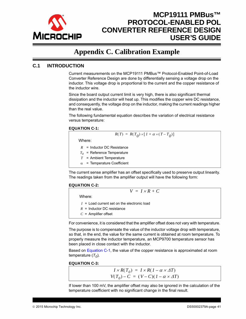
Current measurements on the MCP19111 PMBus™ Protocol-Enabled Point-of-Load Converter Reference Design are done by differentially sensing a voltage drop on the inductor. This voltage drop is proportional to the current and the copper resistance of the inductor wire.
Since the board output current limit is very high, there is also significant thermal dissipation and the inductor will heat up. This modifies the copper wire DC resistance, and consequently, the voltage drop on the inductor, making the current readings higher than the real value.
The following fundamental equation describes the variation of electrical resistance versus temperature:
EQUATION C-1:
The current sense amplifier has an offset specifically used to preserve output linearity. The readings taken from the amplifier output will have the following form:
EQUATION C-2:
For convenience, it is considered that the amplifier offset does not vary with temperature.
The purpose is to compensate the value of the inductor voltage drop with temperature, so that, in the end, the value for the same current is obtained at room temperature. To properly measure the inductor temperature, an MCP9700 temperature sensor has been placed in close contact with the inductor.
Based on Equation C-1, the value of the copper resistance is approximated at room temperature (T0).
EQUATION C-3:
If lower than 100 mV, the amplifier offset may also be ignored in the calculation of the temperature coefficient with no significant change in the final result.
R T R T0 1 T T0– + =
Where:
R = Inductor DC Resistance
T0 = Reference Temperature
T = Ambient Temperature
= Temperature Coefficient
V I R C+=Where:
I = Load current set on the electronic load
R = Inductor DC resistance
C = Amplifier offset
I R T0 I R 1 T– =V T0 C– V C– 1 T– =
2015 Microchip Technology Inc. DS50002379A-page 41

MCP19111 PMBus™ Protocol-Enabled POL Converter Reference Design
C.2 CONFIGURATION REQUIREMENTS
To properly calibrate the board current reading, the user needs the following tools:
• 12V power supply• PMBMonitor GUI running on a PC connected to the board via USB• 20A capable electronic load
C.2.1 Calibration
To calibrate the MCP19111 PMBus™ Protocol-Enabled Point-of-Load Converter Reference Design, proceed to the following steps:
FIGURE C-1: MCP19111 Calibration Values Example.
1. Connect the PC with the GUI installed to the board and power-up the board. Go to the Developer menu in the GUI and select the Calibration tab.
2. Set the low test current to 1A and write the value in the first “Current” field, in the IOUT Settings Panel. Set this current on the external load as accurate as possible. Press the corresponding Read button. In this calibration example, a voltage of 0.247V is obtained in the corresponding “Voltage” field.
3. Set the high test current to 17A, write the value in the second “Current” field and set this output current on the external load. Press the corresponding Read button. In this calibration example, the result is 3.063V. Write down the result.
4. Press the Calculate button to update values. Write down the “ADC(T0)” value. This value will later be used to compensate all current readings. The “ADC(T0)” value and the second voltage value must be read simultaneously.
For this example, the measurement was taken at +27°C, resulting in a reading of 770 mV or 631 ADC units (4x10-bit samples summed together).
WARNING
Keep constant board temperature around ambient during Steps 2 to 4 to obtain accurate values. Use an external cooling device on the board to prevent heating while drawing 17A.
DS50002379A-page 42 2015 Microchip Technology Inc.

Calibration Example
5. Press Send from the bottom of the IOUT Settings Panel. The coefficients are used in a first-order polynomial to calculate the output current based on the readings from the current amplifier. These coefficients are calculated using the amplifier offset and the inductor resistance at room temperature.
Before the next steps, stop the external cooling device and make sure the board heats up to around 70-80°C. Cover it up, if necessary. Ideally, a forced temperature enclosure should be used, but this can also be done on a laboratory bench.
6. Press the Read button on the 17A row and write down the result. For this example, the reading is 3.516V. Write this down.
7. Press the Calculate button again and write down the “ADC(T0)” value. For the calibration example, the final temperature is +70°C, resulting in a temperature reading of 1200 mV or 983 ADC units. This is the “T” value later used in the calculations.
8. Start the calculations. Even if the values are shown as 12-bit (4x10-bit) results, the internal calculations only use 10-bit values for temperature and voltage. Using a different resolution will affect the α calculation.
Do the following calculations:
- Divide the temperature ADC results by 4.
- Round the results to the nearest integer if necessary.
For calculating the voltage ADC units, use a 5V reference.
Two temperature points and two voltages are required to calculate the temperature coefficient:
EXAMPLE C-1:
Use the simplest form of the equation:
EQUATION C-4:
Since all calculations are done using integer arithmetic, the temperature coefficient is scaled internally by 214 or 16384.
EQUATION C-5:
9. In the “ALPHA” field from the IOUT Settings Panel, write the rounded value (24) and press the associated Send button.
10. Go to the Status menu and press the StoreALL button to save all of the calibration values. The calibration is now finished and the board should indicate the correct load current at any operating temperature.
27°C 0.770V 631 ADC (12-bit) 158 ADC (10-bit)
70°C 1.200V 931 ADC (12-bit) 246 ADC (10-bit)
= 246 ADC – 156 ADC = 88 ADC
17A @ 27°C V(T0) = 3.063
17A @ 70°C V(T) = 3.516V
V T0 V T 1 T– =
3.063 3.516 1 88 – =
0.001464=
ALPHA 0.001464 16384 23.98==
2015 Microchip Technology Inc. DS50002379A-page 43

DS50002379A-page 44 2015 Microchip Technology Inc.
AMERICASCorporate Office2355 West Chandler Blvd.Chandler, AZ 85224-6199Tel: 480-792-7200 Fax: 480-792-7277Technical Support: http://www.microchip.com/supportWeb Address: www.microchip.com
AtlantaDuluth, GA Tel: 678-957-9614 Fax: 678-957-1455
Austin, TXTel: 512-257-3370
BostonWestborough, MA Tel: 774-760-0087 Fax: 774-760-0088
ChicagoItasca, IL Tel: 630-285-0071 Fax: 630-285-0075
ClevelandIndependence, OH Tel: 216-447-0464 Fax: 216-447-0643
DallasAddison, TX Tel: 972-818-7423 Fax: 972-818-2924
DetroitNovi, MI Tel: 248-848-4000
Houston, TX Tel: 281-894-5983
IndianapolisNoblesville, IN Tel: 317-773-8323Fax: 317-773-5453
Los AngelesMission Viejo, CA Tel: 949-462-9523 Fax: 949-462-9608
New York, NY Tel: 631-435-6000
San Jose, CA Tel: 408-735-9110
Canada - TorontoTel: 905-673-0699 Fax: 905-673-6509
ASIA/PACIFICAsia Pacific OfficeSuites 3707-14, 37th FloorTower 6, The GatewayHarbour City, Kowloon
Hong KongTel: 852-2943-5100Fax: 852-2401-3431
Australia - SydneyTel: 61-2-9868-6733Fax: 61-2-9868-6755
China - BeijingTel: 86-10-8569-7000 Fax: 86-10-8528-2104
China - ChengduTel: 86-28-8665-5511Fax: 86-28-8665-7889
China - ChongqingTel: 86-23-8980-9588Fax: 86-23-8980-9500
China - DongguanTel: 86-769-8702-9880
China - HangzhouTel: 86-571-8792-8115 Fax: 86-571-8792-8116
China - Hong Kong SARTel: 852-2943-5100 Fax: 852-2401-3431
China - NanjingTel: 86-25-8473-2460Fax: 86-25-8473-2470
China - QingdaoTel: 86-532-8502-7355Fax: 86-532-8502-7205
China - ShanghaiTel: 86-21-5407-5533 Fax: 86-21-5407-5066
China - ShenyangTel: 86-24-2334-2829Fax: 86-24-2334-2393
China - ShenzhenTel: 86-755-8864-2200 Fax: 86-755-8203-1760
China - WuhanTel: 86-27-5980-5300Fax: 86-27-5980-5118
China - XianTel: 86-29-8833-7252Fax: 86-29-8833-7256
ASIA/PACIFICChina - XiamenTel: 86-592-2388138 Fax: 86-592-2388130
China - ZhuhaiTel: 86-756-3210040 Fax: 86-756-3210049
India - BangaloreTel: 91-80-3090-4444 Fax: 91-80-3090-4123
India - New DelhiTel: 91-11-4160-8631Fax: 91-11-4160-8632
India - PuneTel: 91-20-3019-1500
Japan - OsakaTel: 81-6-6152-7160 Fax: 81-6-6152-9310
Japan - TokyoTel: 81-3-6880- 3770 Fax: 81-3-6880-3771
Korea - DaeguTel: 82-53-744-4301Fax: 82-53-744-4302
Korea - SeoulTel: 82-2-554-7200Fax: 82-2-558-5932 or 82-2-558-5934
Malaysia - Kuala LumpurTel: 60-3-6201-9857Fax: 60-3-6201-9859
Malaysia - PenangTel: 60-4-227-8870Fax: 60-4-227-4068
Philippines - ManilaTel: 63-2-634-9065Fax: 63-2-634-9069
SingaporeTel: 65-6334-8870Fax: 65-6334-8850
Taiwan - Hsin ChuTel: 886-3-5778-366Fax: 886-3-5770-955
Taiwan - KaohsiungTel: 886-7-213-7828
Taiwan - TaipeiTel: 886-2-2508-8600 Fax: 886-2-2508-0102
Thailand - BangkokTel: 66-2-694-1351Fax: 66-2-694-1350
EUROPEAustria - WelsTel: 43-7242-2244-39Fax: 43-7242-2244-393
Denmark - CopenhagenTel: 45-4450-2828 Fax: 45-4485-2829
France - ParisTel: 33-1-69-53-63-20 Fax: 33-1-69-30-90-79
Germany - DusseldorfTel: 49-2129-3766400
Germany - MunichTel: 49-89-627-144-0 Fax: 49-89-627-144-44
Germany - PforzheimTel: 49-7231-424750
Italy - Milan Tel: 39-0331-742611 Fax: 39-0331-466781
Italy - VeniceTel: 39-049-7625286
Netherlands - DrunenTel: 31-416-690399 Fax: 31-416-690340
Poland - WarsawTel: 48-22-3325737
Spain - MadridTel: 34-91-708-08-90Fax: 34-91-708-08-91
Sweden - StockholmTel: 46-8-5090-4654
UK - WokinghamTel: 44-118-921-5800Fax: 44-118-921-5820
Worldwide Sales and Service
01/27/15