Mazin B. Abdulrahman, Shakir A. Salih, Rusul J ...
13
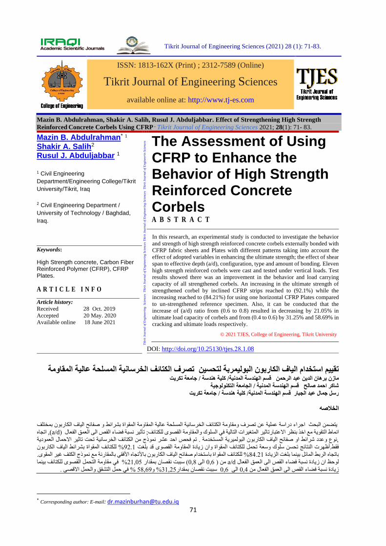
71 Tikrit Journal of Engineering Sciences (2021) 28 (1): 71-83. ISSN: 1813-162X (Print) ; 2312-7589 (Online) Tikrit Journal of Engineering Sciences available online at: http://www.tj-es.com Mazin B. Abdulrahman, Shakir A. Salih, Rusul J. Abduljabbar. Effect of Strengthening High Strength Reinforced Concrete Corbels Using CFRP . Tikrit Journal of Engineering Sciences 2021; 28(1): 71- 83. Mazin B. Abdulrahman * 1 Shakir A. Salih 2 Rusul J. Abduljabbar 1 1 Civil Engineering Department/Engineering College/Tikrit University/Tikrit, Iraq 2 Civil Engineering Department / University of Technology / Baghdad, Iraq. Keywords: High Strength concrete, Carbon Fiber Reinforced Polymer (CFRP), CFRP Plates. ARTICLE INFO Article history: Received 28 Oct. 2019 Accepted 20 May. 2020 Available online 18 June 2021 Tikrit Journal of Engineering Sciences Tikrit Journal of Engineering Sciences Tikrit Journal of Engineering Sciences Tikrit Journal of Engineerin Sciences The Assessment of Using CFRP to Enhance the Behavior of High Strength Reinforced Concrete Corbels ABSTRACT In this research, an experimental study is conducted to investigate the behavior and strength of high strength reinforced concrete corbels externally bonded with CFRP fabric sheets and Plates with different patterns taking into account the effect of adopted variables in enhancing the ultimate strength; the effect of shear span to effective depth (a/d), configuration, type and amount of bonding. Eleven high strength reinforced corbels were cast and tested under vertical loads. Test results showed there was an improvement in the behavior and load carrying capacity of all strengthened corbels. An increasing in the ultimate strength of strengthened corbel by inclined CFRP strips reached to (92.1%) while the increasing reached to (84.21%) for using one horizontal CFRP Plates compared to un-strengthened reference specimen. Also, it can be conducted that the increase of (a/d) ratio from (0.6 to 0.8) resulted in decreasing by 21.05% in ultimate load capacity of corbels and from (0.4 to 0.6) by 31.25% and 58.69% in cracking and ultimate loads respectively. © 2021 TJES, College of Engineering, Tikrit University DOI: http://doi.org/10.25130/tjes.28.1.08 قاومةلية الممسلحة عانية اللخرسائف الكتا تصرف اوليمربة لتحسينون البلكاربف اليا استخدام ا تقييممدنية/ كليةم الهندسة ال قس الدين عبد الرحمن مازن برهان هندسة/ جامعةكريت تمد صالحكر اح شام الهندسة قس المدنية/ معة التكنولوجيةلجا امدنية/ كليةم الهندسة ال قسلجبارل عبد ا رسل جما هندسة/ جامعةكريت تص الخ هلكاربونف اليائح ائط و صفا المقواة بشراقاومةلية الممسلحة عانية اللخرسائف الكتاومة الية عن تصرف ومقااء دراسة عم اجر يتضمن البحث بمختلفة فيلتاليغيرات اثير المتبارتاعتط التقوية مع اخذ بنظر انما ا اللكتائف;مة القصوى للمقاوك وا سلوفعالص الى العمق الء الق تأثير نسبة فضا( (a/d تجاه , ا الحمالثير ا تاحتلخرسانية تئف الكتاوذج من اص احد عشر نمة . تم فحستخدمرية المون البولميلكاربف اليائح او صفاد شرائط ا وعد ,نوع عموديةقاومةدة المن زيااة وائف المقولكتا لك وسعة تحملن سلوائج تحس النت فقط.أظهرتصوى قد بلغت الق92.1 لكاربونف اليائف المقواة بشرائط الكتا ل% لزيادة بلغت امائل بينماه الربط ال باتجا84.21 لكاربون بف اليائح ام صفاستخداة بائف المقوالكتا ل% اع نموذج الكتف غير المقوى.قارنة مفقي بالمه ا تجافعالص الى العمق الء الق نسبة فضان زيادة لوحظ اa/d م ن( 0,6 الى0,8 ) سبب تن بمقدار نقصا21,05 لكتائف القصوى لتحملومة ال في مقا% بينمافعال منص الى العمق الء الق نسبة فضا زيادة0,4 الى0,6 قصان سببت ن بمقدار31,25 و% 58,69 في% حملقصى .حمل اق وال التشق* Corresponding author: E-mail: [email protected]
Transcript of Mazin B. Abdulrahman, Shakir A. Salih, Rusul J ...
71
Tikrit Journal of Engineering Sciences (2021) 28 (1): 71-83.
ISSN: 1813-162X (Print) ; 2312-7589 (Online)
Tikrit Journal of Engineering Sciences
available online at: http://www.tj-es.com
Mazin B. Abdulrahman, Shakir A. Salih, Rusul J. Abduljabbar. Effect of Strengthening High Strength
Reinforced Concrete Corbels Using CFRP . Tikrit Journal of Engineering Sciences 2021; 28(1): 71- 83.
Mazin B. Abdulrahman* 1
Shakir A. Salih2
Rusul J. Abduljabbar 1 1 Civil Engineering
Department/Engineering College/Tikrit
University/Tikrit, Iraq
2 Civil Engineering Department /
University of Technology / Baghdad,
Iraq.
Keywords:
High Strength concrete, Carbon Fiber Reinforced Polymer (CFRP), CFRP Plates.
A R T I C L E I N F O
Article history: Received 28 Oct. 2019
Accepted 20 May. 2020
Available online 18 June 2021
Tik
rit
Journ
al
of
Engin
eeri
ng
Sci
ence
s T
ikri
t Jo
urn
al
of
Engin
eeri
ng S
cien
ces
Tik
rit
Journ
al
of
Engin
eeri
ng S
cien
ces
Tik
rit
Jou
rnal
of
En
gin
eeri
n S
cien
ces The Assessment of Using
CFRP to Enhance the Behavior of High Strength Reinforced Concrete Corbels
A B S T R A C T
In this research, an experimental study is conducted to investigate the behavior
and strength of high strength reinforced concrete corbels externally bonded with
CFRP fabric sheets and Plates with different patterns taking into account the
effect of adopted variables in enhancing the ultimate strength; the effect of shear
span to effective depth (a/d), configuration, type and amount of bonding. Eleven
high strength reinforced corbels were cast and tested under vertical loads. Test
results showed there was an improvement in the behavior and load carrying
capacity of all strengthened corbels. An increasing in the ultimate strength of
strengthened corbel by inclined CFRP strips reached to (92.1%) while the
increasing reached to (84.21%) for using one horizontal CFRP Plates compared
to un-strengthened reference specimen. Also, it can be conducted that the
increase of (a/d) ratio from (0.6 to 0.8) resulted in decreasing by 21.05% in
ultimate load capacity of corbels and from (0.4 to 0.6) by 31.25% and 58.69% in
cracking and ultimate loads respectively.
© 2021 TJES, College of Engineering, Tikrit University
DOI: http://doi.org/10.25130/tjes.28.1.08
تقييم استخدام الياف الكاربون البوليمربة لتحسين تصرف الكتائف الخرسانية المسلحة عالية المقاومة تكريت جامعة /هندسة مازن برهان الدين عبد الرحمن قسم الهندسة المدنية/ كلية
الجامعة التكنولوجية / المدنيةقسم الهندسة شاكر احمد صالح
تكريت جامعة /هندسة رسل جمال عبد الجبار قسم الهندسة المدنية/ كلية
ه الخلاص
بمختلف يتضمن البحث اجراء دراسة عملية عن تصرف ومقاومة الكتائف الخرسانية المسلحة عالية المقاومة المقواة بشرائط و صفائح الياف الكاربون
, اتجاه a/d))تأثير نسبة فضاء القص الى العمق الفعال سلوك والمقاومة القصوى للكتائف; الانماط التقوية مع اخذ بنظر الاعتبارتاثير المتغيرات التالية في
عمودية ,نوع وعدد شرائط او صفائح الياف الكاربون البولميرية المستخدمة . تم فحص احد عشر نموذج من الكتائف الخرسانية تحت تاثير الاحمال ال
% للكتائف المقواة بشرائط الياف الكاربون 92.1القصوى قد بلغت فقط.أظهرت النتائج تحسن سلوك وسعة تحمل للكتائف المقواة وان زيادة المقاومة
تجاه الأفقي بالمقارنة مع نموذج الكتف غير المقوى. الأ% للكتائف المقواة باستخدام صفائح الياف الكاربون ب84.21باتجاه الربط المائل بينما بلغت الزيادة
بينما % في مقاومة التحمل القصوى للكتائف 21,05نقصان بمقدار تسبب ( 0,8الى 0,6 ) نم a/dلوحظ ان زيادة نسبة فضاء القص الى العمق الفعال
التشقق والحمل الاقصى . حمل % في 58,69% و 31,25بمقدارسببت نقصان 0,6الى 0,4 زيادة نسبة فضاء القص الى العمق الفعال من
* Corresponding author: E-mail: [email protected]
Mazin B. Abdulrahman, Shakir A. Salih, Rusul J. Abduljabbar / Tikrit Journal of Engineering Sciences (2021) 28(1): 71-83.
72
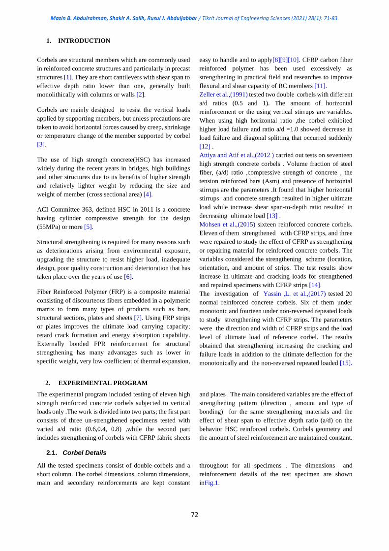
1. INTRODUCTION
Corbels are structural members which are commonly used
in reinforced concrete structures and particularly in precast
structures [1]. They are short cantilevers with shear span to
effective depth ratio lower than one, generally built
monolithically with columns or walls [2].
Corbels are mainly designed to resist the vertical loads
applied by supporting members, but unless precautions are
taken to avoid horizontal forces caused by creep, shrinkage
or temperature change of the member supported by corbel
[3].
The use of high strength concrete(HSC) has increased
widely during the recent years in bridges, high buildings
and other structures due to its benefits of higher strength
and relatively lighter weight by reducing the size and
weight of member (cross sectional area) [4].
ACI Committee 363, defined HSC in 2011 is a concrete
having cylinder compressive strength for the design
(55MPa) or more [5].
Structural strengthening is required for many reasons such
as deteriorations arising from environmental exposure,
upgrading the structure to resist higher load, inadequate
design, poor quality construction and deterioration that has
taken place over the years of use [6].
Fiber Reinforced Polymer (FRP) is a composite material
consisting of discourteous fibers embedded in a polymeric
matrix to form many types of products such as bars,
structural sections, plates and sheets [7]. Using FRP strips
or plates improves the ultimate load carrying capacity;
retard crack formation and energy absorption capability.
Externally bonded FPR reinforcement for structural
strengthening has many advantages such as lower in
specific weight, very low coefficient of thermal expansion,
easy to handle and to apply[8][9][10]. CFRP carbon fiber
reinforced polymer has been used excessively as
strengthening in practical field and researches to improve
flexural and shear capacity of RC members [11].
Zeller et al.,(1991) tested two double corbels with different
a/d ratios (0.5 and 1). The amount of horizontal
reinforcement or the using vertical stirrups are variables.
When using high horizontal ratio ,the corbel exhibited
higher load failure and ratio a/d =1.0 showed decrease in
load failure and diagonal splitting that occurred suddenly
[12] .
Attiya and Atif et al.,(2012 ) carried out tests on seventeen
high strength concrete corbels . Volume fraction of steel
fiber, (a/d) ratio ,compressive strength of concrete , the
tension reinforced bars (Asm) and presence of horizontal
stirrups are the parameters .It found that higher horizontal
stirrups and concrete strength resulted in higher ultimate
load while increase shear span-to-depth ratio resulted in
decreasing ultimate load [13] .
Mohsen et al.,(2015) sixteen reinforced concrete corbels.
Eleven of them strengthened with CFRP strips, and three
were repaired to study the effect of CFRP as strengthening
or repairing material for reinforced concrete corbels. The
variables considered the strengthening scheme (location,
orientation, and amount of strips. The test results show
increase in ultimate and cracking loads for strengthened
and repaired specimens with CFRP strips [14].
The investigation of Yassin ,L. et al.,(2017) tested 20
normal reinforced concrete corbels. Six of them under
monotonic and fourteen under non-reversed repeated loads
to study strengthening with CFRP strips. The parameters
were the direction and width of CFRP strips and the load
level of ultimate load of reference corbel. The results
obtained that strengthening increasing the cracking and
failure loads in addition to the ultimate deflection for the
monotonically and the non-reversed repeated loaded [15].
2. EXPERIMENTAL PROGRAM
The experimental program included testing of eleven high
strength reinforced concrete corbels subjected to vertical
loads only .The work is divided into two parts; the first part
consists of three un-strengthened specimens tested with
varied a/d ratio (0.6,0.4, 0.8) ,while the second part
includes strengthening of corbels with CFRP fabric sheets
and plates . The main considered variables are the effect of
strengthening pattern (direction , amount and type of
bonding) for the same strengthening materials and the
effect of shear span to effective depth ratio (a/d) on the
behavior HSC reinforced corbels. Corbels geometry and
the amount of steel reinforcement are maintained constant.
2.1. Corbel Details
All the tested specimens consist of double-corbels and a
short column. The corbel dimensions, column dimensions,
main and secondary reinforcements are kept constant
throughout for all specimens . The dimensions and
reinforcement details of the test specimen are shown
inFig.1.
Mazin B. Abdulrahman, Shakir A. Salih, Rusul J. Abduljabbar / Tikrit Journal of Engineering Sciences (2021) 28(1): 71-83.
73
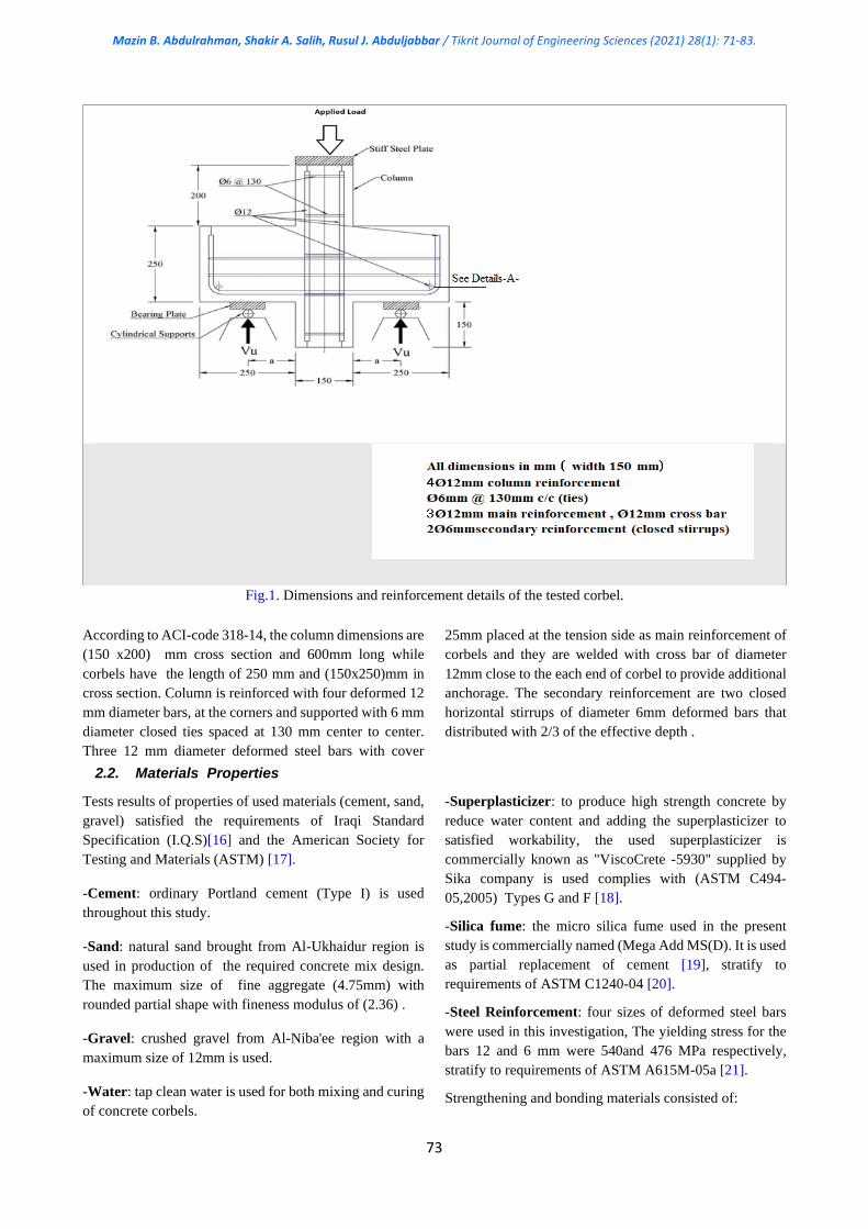
Fig.1. Dimensions and reinforcement details of the tested corbel.
According to ACI-code 318-14, the column dimensions are
(150 x200) mm cross section and 600mm long while
corbels have the length of 250 mm and (150x250)mm in
cross section. Column is reinforced with four deformed 12
mm diameter bars, at the corners and supported with 6 mm
diameter closed ties spaced at 130 mm center to center.
Three 12 mm diameter deformed steel bars with cover
25mm placed at the tension side as main reinforcement of
corbels and they are welded with cross bar of diameter
12mm close to the each end of corbel to provide additional
anchorage. The secondary reinforcement are two closed
horizontal stirrups of diameter 6mm deformed bars that
distributed with 2/3 of the effective depth .
2.2. Materials Properties
Tests results of properties of used materials (cement, sand,
gravel) satisfied the requirements of Iraqi Standard
Specification (I.Q.S)[16] and the American Society for
Testing and Materials (ASTM) [17].
-Cement: ordinary Portland cement (Type I) is used
throughout this study.
-Sand: natural sand brought from Al-Ukhaidur region is
used in production of the required concrete mix design.
The maximum size of fine aggregate (4.75mm) with
rounded partial shape with fineness modulus of (2.36) .
-Gravel: crushed gravel from Al-Niba'ee region with a
maximum size of 12mm is used.
-Water: tap clean water is used for both mixing and curing
of concrete corbels.
-Superplasticizer: to produce high strength concrete by
reduce water content and adding the superplasticizer to
satisfied workability, the used superplasticizer is
commercially known as "ViscoCrete -5930" supplied by
Sika company is used complies with (ASTM C494-
05,2005) Types G and F [18].
-Silica fume: the micro silica fume used in the present
study is commercially named (Mega Add MS(D). It is used
as partial replacement of cement [19], stratify to
requirements of ASTM C1240-04 [20].
-Steel Reinforcement: four sizes of deformed steel bars
were used in this investigation, The yielding stress for the
bars 12 and 6 mm were 540and 476 MPa respectively,
stratify to requirements of ASTM A615M-05a [21].
Strengthening and bonding materials consisted of:
Mazin B. Abdulrahman, Shakir A. Salih, Rusul J. Abduljabbar / Tikrit Journal of Engineering Sciences (2021) 28(1): 71-83.
74
a- A woven black unidirectional Carbon Fibers
Reinforced Polymers CFRP fabric sheets, named Sika
Wrap®-300 C, has thickness of 0.167 mm ,tensile strength
of 4000 MPa and modulus of elasticity 230,000 MPa ,as
supplied by manufacture.
b- A unidirectional pultruded corrosion resistant Carbon
Fiber Reinforced Polymers CFRP plates, named Sika
CarboDur S512, has thickness of 1.2 mm, modulus of
elasticity of 165,000 MPa and tensile strength of more than
2800 MPa and ,as given by manufacture.
c- Two compatible epoxy resins, Sikadur®-330 and
Sikadur-30LP manufactured by Sika Company.
2.3 Mix Design
According to ASTM method in (Nevile,2000) [22] [23],
three trial mixes were made to obtain high strength
concrete mix design of cement content of 500 kg/m3 and
water/cement (w/c) of 0.25 with a slump of 100 mm. A
proportion by weight (1:1.5:1.92) with superplasticizer
ratio 2.5% of cement content and silica fume content of
10% of cement weight was found to obtain a compressive
strength of 72.59 MPa.
2.4 Preparing of the Specimens
Casting and curing were carried out in the Structural
Laboratory of University of Technology, Iraq. The
concrete mixer was cleaned and moistened before use, all
quantities were weighed and added in the following order,
gravel and sand were first mixed in with required water,
then silica fume and cement were added and mixed, finally
superplasticizer with the mixing water were added and
remixed for three minutes.
After 28 days of curing all specimens were left to dry and
then the strengthening materials were applied.
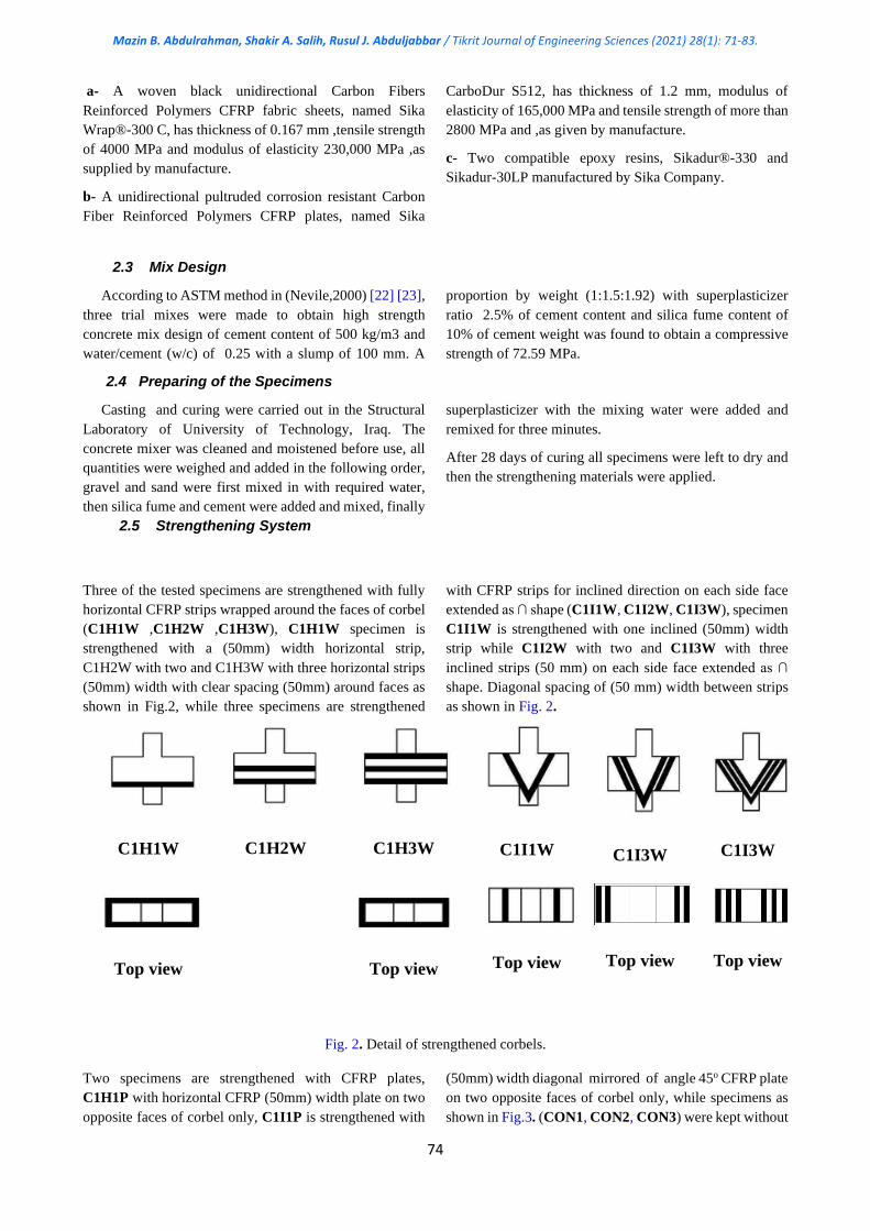
2.5 Strengthening System
Three of the tested specimens are strengthened with fully
horizontal CFRP strips wrapped around the faces of corbel
(C1H1W ,C1H2W ,C1H3W), C1H1W specimen is
strengthened with a (50mm) width horizontal strip,
C1H2W with two and C1H3W with three horizontal strips
(50mm) width with clear spacing (50mm) around faces as
shown in Fig.2, while three specimens are strengthened
with CFRP strips for inclined direction on each side face
extended as ∩ shape (C1I1W, C1I2W, C1I3W), specimen
C1I1W is strengthened with one inclined (50mm) width
strip while C1I2W with two and C1I3W with three
inclined strips (50 mm) on each side face extended as ∩
shape. Diagonal spacing of (50 mm) width between strips
as shown in Fig. 2.
C1H1W
C1H2W
C1H3W
C1I1W
C1I3W
C1I3W
Top view
Top view
Top view
Top view
Top view
Fig. 2. Detail of strengthened corbels.
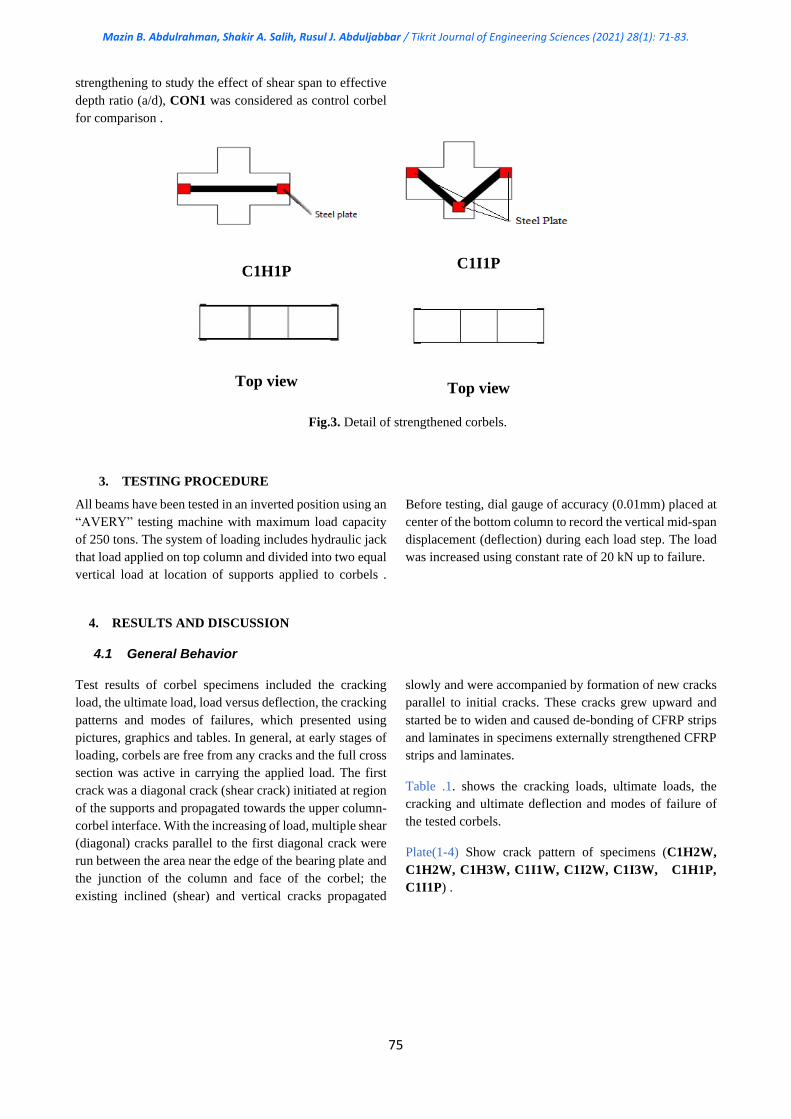
Two specimens are strengthened with CFRP plates,
C1H1P with horizontal CFRP (50mm) width plate on two
opposite faces of corbel only, C1I1P is strengthened with
(50mm) width diagonal mirrored of angle 45o CFRP plate
on two opposite faces of corbel only, while specimens as
shown in Fig.3. (CON1, CON2, CON3) were kept without
Mazin B. Abdulrahman, Shakir A. Salih, Rusul J. Abduljabbar / Tikrit Journal of Engineering Sciences (2021) 28(1): 71-83.
75
strengthening to study the effect of shear span to effective
depth ratio (a/d), CON1 was considered as control corbel
for comparison .
C1H1P
C1I1P
Top view
Top view
Fig.3. Detail of strengthened corbels.
3. TESTING PROCEDURE
All beams have been tested in an inverted position using an
“AVERY” testing machine with maximum load capacity
of 250 tons. The system of loading includes hydraulic jack
that load applied on top column and divided into two equal
vertical load at location of supports applied to corbels .
Before testing, dial gauge of accuracy (0.01mm) placed at
center of the bottom column to record the vertical mid-span
displacement (deflection) during each load step. The load
was increased using constant rate of 20 kN up to failure.
4. RESULTS AND DISCUSSION
4.1 General Behavior
Test results of corbel specimens included the cracking
load, the ultimate load, load versus deflection, the cracking
patterns and modes of failures, which presented using
pictures, graphics and tables. In general, at early stages of
loading, corbels are free from any cracks and the full cross
section was active in carrying the applied load. The first
crack was a diagonal crack (shear crack) initiated at region
of the supports and propagated towards the upper column-
corbel interface. With the increasing of load, multiple shear
(diagonal) cracks parallel to the first diagonal crack were
run between the area near the edge of the bearing plate and
the junction of the column and face of the corbel; the
existing inclined (shear) and vertical cracks propagated
slowly and were accompanied by formation of new cracks
parallel to initial cracks. These cracks grew upward and
started be to widen and caused de-bonding of CFRP strips
and laminates in specimens externally strengthened CFRP
strips and laminates.
Table .1. shows the cracking loads, ultimate loads, the
cracking and ultimate deflection and modes of failure of
the tested corbels.
Plate(1-4) Show crack pattern of specimens (C1H2W,
C1H2W, C1H3W, C1I1W, C1I2W, C1I3W, C1H1P,
C1I1P) .
Mazin B. Abdulrahman, Shakir A. Salih, Rusul J. Abduljabbar / Tikrit Journal of Engineering Sciences (2021) 28(1): 71-83.
76
Table(1)
Results of tested corbels specimens.
Specimen a/d Pcr (kN) ∆cr(mm) Pu (kN) ∆u(mm) Mode of Failure
CON1 0.6 220 1.73 380 2.9 Diagonal splitting
CON2 0.4 320 1.7 920 3.93 Diagonal splitting
CON3 0.8 220 3.24 300 4.63 Diagonal splitting
C1H1W 0.6 260 1.7 580 3.1 Diagonal splitting +CFRP de-
bonding
C1H2W 0.6 280 1.42 630 2.7 Diagonal splitting +CFRP de-
bonding
C1H3W 0.6 340 1.45 700 3.2 Diagonal splitting +CFRP de-
bonding
C1I1W 0.6 280 1.29 710 3.70 Diagonal splitting +CFRP de-
bonding
C1I2W 0.6 320 2.57 720 4.7 Diagonal splitting +CFRP de-
bonding
C1I3W 0.6 480 3.33 730 4.37 Diagonal splitting +CFRP de-
bonding
C1H1P 0.6 280 2.69 700 3.37 Diagonal splitting +CFRP de-
bonding
C1I1P 0.6 340 2.8 480 3.58 Diagonal splitting +CFRP de-
bonding
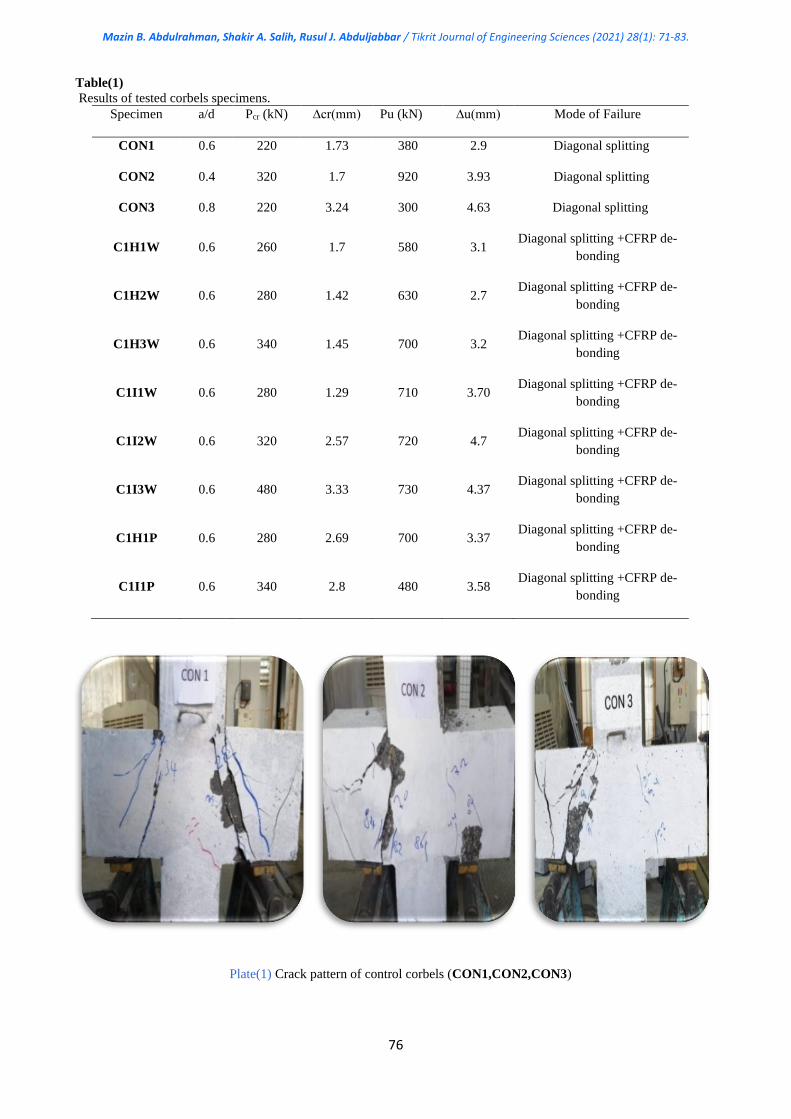
Plate(1) Crack pattern of control corbels (CON1,CON2,CON3)
Mazin B. Abdulrahman, Shakir A. Salih, Rusul J. Abduljabbar / Tikrit Journal of Engineering Sciences (2021) 28(1): 71-83.
77
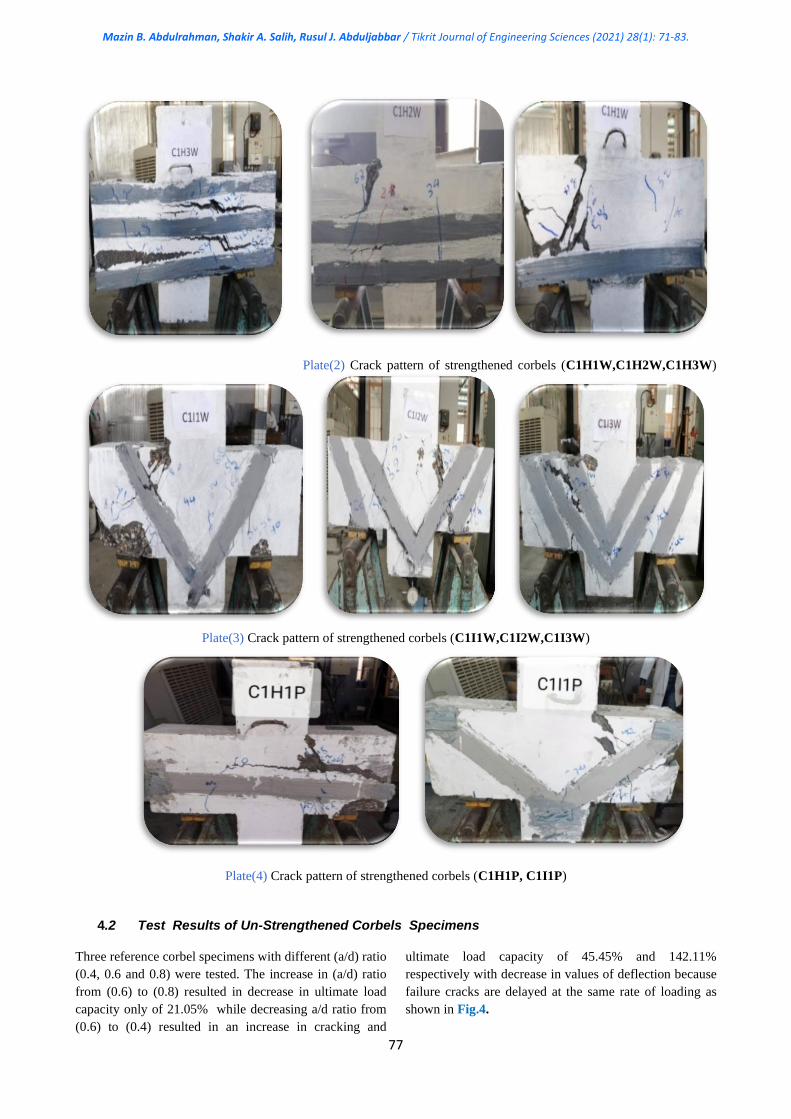
Plate(2) Crack pattern of strengthened corbels (C1H1W,C1H2W,C1H3W)
Plate(3) Crack pattern of strengthened corbels (C1I1W,C1I2W,C1I3W)
Plate(4) Crack pattern of strengthened corbels (C1H1P, C1I1P)
4.2 Test Results of Un-Strengthened Corbels Specimens
Three reference corbel specimens with different (a/d) ratio
(0.4, 0.6 and 0.8) were tested. The increase in (a/d) ratio
from (0.6) to (0.8) resulted in decrease in ultimate load
capacity only of 21.05% while decreasing a/d ratio from
(0.6) to (0.4) resulted in an increase in cracking and
ultimate load capacity of 45.45% and 142.11%
respectively with decrease in values of deflection because
failure cracks are delayed at the same rate of loading as
shown in Fig.4.
Mazin B. Abdulrahman, Shakir A. Salih, Rusul J. Abduljabbar / Tikrit Journal of Engineering Sciences (2021) 28(1): 71-83.
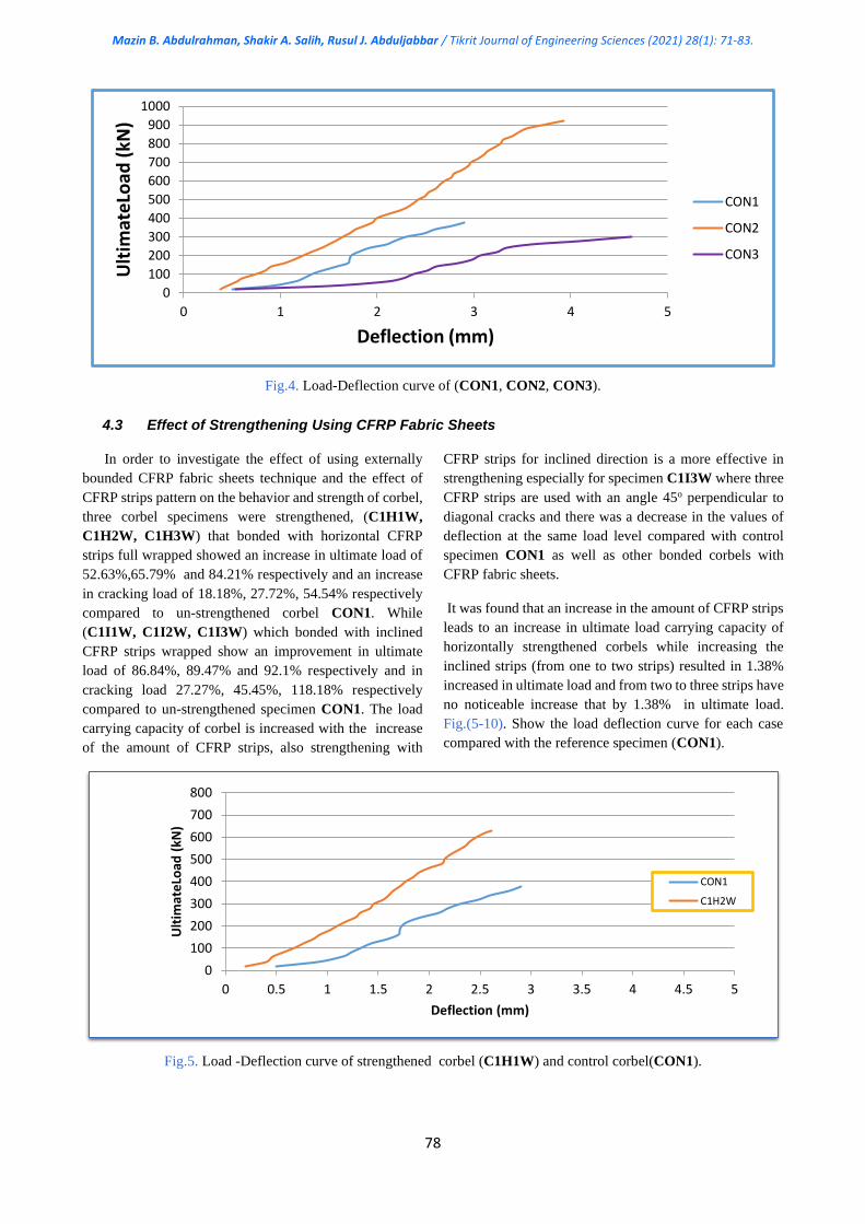
78
Fig.4. Load-Deflection curve of (CON1, CON2, CON3).
4.3 Effect of Strengthening Using CFRP Fabric Sheets
In order to investigate the effect of using externally
bounded CFRP fabric sheets technique and the effect of
CFRP strips pattern on the behavior and strength of corbel,
three corbel specimens were strengthened, (C1H1W,
C1H2W, C1H3W) that bonded with horizontal CFRP
strips full wrapped showed an increase in ultimate load of
52.63%,65.79% and 84.21% respectively and an increase
in cracking load of 18.18%, 27.72%, 54.54% respectively
compared to un-strengthened corbel CON1. While
(C1I1W, C1I2W, C1I3W) which bonded with inclined
CFRP strips wrapped show an improvement in ultimate
load of 86.84%, 89.47% and 92.1% respectively and in
cracking load 27.27%, 45.45%, 118.18% respectively
compared to un-strengthened specimen CON1. The load
carrying capacity of corbel is increased with the increase
of the amount of CFRP strips, also strengthening with
CFRP strips for inclined direction is a more effective in
strengthening especially for specimen C1I3W where three
CFRP strips are used with an angle 45o perpendicular to
diagonal cracks and there was a decrease in the values of
deflection at the same load level compared with control
specimen CON1 as well as other bonded corbels with
CFRP fabric sheets.
It was found that an increase in the amount of CFRP strips
leads to an increase in ultimate load carrying capacity of
horizontally strengthened corbels while increasing the
inclined strips (from one to two strips) resulted in 1.38%
increased in ultimate load and from two to three strips have
no noticeable increase that by 1.38% in ultimate load.
Fig.(5-10). Show the load deflection curve for each case
compared with the reference specimen (CON1).
Fig.5. Load -Deflection curve of strengthened corbel (C1H1W) and control corbel(CON1).
0
100
200
300
400
500
600
700
800
900
1000
0 1 2 3 4 5
Ult
imat
eLo
ad (
kN)
Deflection (mm)
CON1
CON2
CON3
0
100
200
300
400
500
600
700
800
0 0.5 1 1.5 2 2.5 3 3.5 4 4.5 5
Ult
imat
eLo
ad (
kN)
Deflection (mm)
CON1
C1H2W
Mazin B. Abdulrahman, Shakir A. Salih, Rusul J. Abduljabbar / Tikrit Journal of Engineering Sciences (2021) 28(1): 71-83.
79
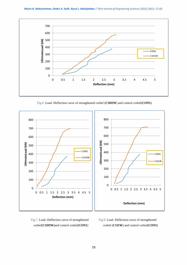
Fig.6. Load -Deflection curve of strengthened corbel (C1H2W) and control corbel(CON1).
Fig.7. Load -Deflection curve of strengthened Fig.8. Load -Deflection curve of strengthened
corbel(C1H3W)and control corbel(CON1) corbel (C1I1W) and control corbel(CON1)
0
100
200
300
400
500
600
700
800
0 0.5 1 1.5 2 2.5 3 3.5 4 4.5 5
Ult
imat
eLo
ad (
kN)
Deflection (mm)
CON1
C1H3W
0
100
200
300
400
500
600
700
800
0 0.5 1 1.5 2 2.5 3 3.5 4 4.5 5
Ult
imat
eLo
ad (
kN)
Deflection (mm)
CON1
C1I1W
0
100
200
300
400
500
600
700
0 0.5 1 1.5 2 2.5 3 3.5 4 4.5 5
Ult
imat
eLo
ad (
kN)
Deflection (mm)
CON1
C1H1W
Mazin B. Abdulrahman, Shakir A. Salih, Rusul J. Abduljabbar / Tikrit Journal of Engineering Sciences (2021) 28(1): 71-83.
80
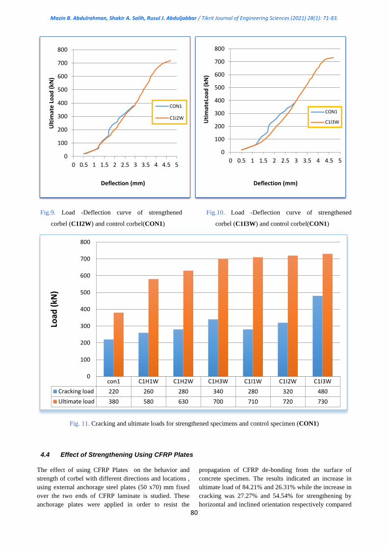
Fig.9. Load -Deflection curve of strengthened Fig.10. Load -Deflection curve of strengthened
corbel (C1I2W) and control corbel(CON1) corbel (C1I3W) and control corbel(CON1)
Fig. 11. Cracking and ultimate loads for strengthened specimens and control specimen (CON1)
4.4 Effect of Strengthening Using CFRP Plates
The effect of using CFRP Plates on the behavior and
strength of corbel with different directions and locations ,
using external anchorage steel plates (50 x70) mm fixed
over the two ends of CFRP laminate is studied. These
anchorage plates were applied in order to resist the
propagation of CFRP de-bonding from the surface of
concrete specimen. The results indicated an increase in
ultimate load of 84.21% and 26.31% while the increase in
cracking was 27.27% and 54.54% for strengthening by
horizontal and inclined orientation respectively compared
0
100
200
300
400
500
600
700
800
0 0.5 1 1.5 2 2.5 3 3.5 4 4.5 5
Ult
imat
e L
oad
(kN
)
Deflection (mm)
CON1
C1I2W
0
100
200
300
400
500
600
700
800
0 0.5 1 1.5 2 2.5 3 3.5 4 4.5 5
Uti
mat
eLo
ad (
kN)
Deflection (mm)
CON1
C1I3W
con1 C1H1W C1H2W C1H3W C1I1W C1I2W C1I3W
Cracking load 220 260 280 340 280 320 480
Ultimate load 380 580 630 700 710 720 730
0
100
200
300
400
500
600
700
800
Load
(kN
)

Mazin B. Abdulrahman, Shakir A. Salih, Rusul J. Abduljabbar / Tikrit Journal of Engineering Sciences (2021) 28(1): 71-83.
81
to reference specimen CON1. It was concluded that
C1HIP strengthening by horizontal direction gave better
improvment in strength than strengthening by inclined
direction for specimen C1I1P due to debonding of carbon
fiber reinforced polymers (CFRP) at the ends of the CFRP
Plates. Fig.12. and Fig.13 show the load -deflection curve
for C1HIP and C1I1P specimens compared with the
reference specimen (CON1). For these specimen
debonding of (CFRP) at the ends of the CFRP
reinforcement play an important role in failure of specimen
C1I1P due to more ends near flexure and shear cracks and
area of highest stresses in this strengthening configuration.
Fig.12. Load-Deflection Curve of strengthened corbel (C1H1P) and control corbel(CON1).
Fig.13. Load-Deflection Curve of strengthened corbel (C1I1P) and control corbel(CON1).
0
100
200
300
400
500
600
700
800
0 0.5 1 1.5 2 2.5 3 3.5 4 4.5 5
Ult
imat
e L
oad
(kN
)
Deflection (mm)
CON1 C1H1P
0
100
200
300
400
500
600
700
0 0.5 1 1.5 2 2.5 3 3.5 4 4.5 5
Ult
imat
e L
oad
(kN
)
Deflecion (mm)
CON1 C1I1P
Mazin B. Abdulrahman, Shakir A. Salih, Rusul J. Abduljabbar / Tikrit Journal of Engineering Sciences (2021) 28(1): 71-83.
82
5. CONCLUSIONS
1–It was found that the decrease in the shear span to
effective depth ratio (a/d) from 0.6 to 0.4 increases the
cracking load by 45% and increases the ultimate load by
142.1% while by increasing the (a/d) ratio from 0.6 to 0.8,
there was no variation in the cracking load and decrease in
the ultimate load by about 21% is occurred.
2- Tests results of strengthening HSC corbels with CFRP
strips showed an improvement in the resistance for
cracking of these corbels, the increase in the cracking load
reached to 54.54 % for horizontal full wrapped
configuration and 118.18% for inclined configuration
3-An increase in corbel cracking load and ultimate load
was observed with an increase the amount of CFRP strips
in horizontal and diagonal orientation
4-The location, direction, and amount of CFRP strips play
an important role in enhancing the stiffness, cracking and
ultimate loads; therefore the diagonal wrapped as ∩ shape
configuration strengthening technique was found to give
better results (additional increasing of cracking load and
ultimate load) as compared to specimens that were un-
strengthened or strengthened with horizontal full wrapped
as a box shape.
5-Externally bonded with CFRP plates generally showed a
significant increase in ultimate loads which reached to 84.1
% for corbels strengthened with CFRP plates as horizontal
layers on two faces of corbel only while the increase in
ultimate loads of 26.31% for strengthened for inclined
orientation compared to reference specimen CON1.
6-Strengthening with CFRP plates showed higher load
bearing capacity and higher deflection up to failure
compared with the same amount of CFRP fabric sheets
used in strengthening corbels.
REFERENCES
[1]Campione, G., Mendola ,L. La. and Papia M.
,"Flexural Behaviour Of Concrete Corbels Containing
Steel Fibers Or Wrapped With FRP Sheets", Materials
and Structures, 2005, 617-625.
[2] Kriz, L.B. and Raths, C.H. , "Connections in Precast
Concrete Structures-Strength of Corbels", PCI journal,
1965, 10 (1) , 16-61.
[3] Yousif , A. R., " Prediction Of Ultimate Load Capacity
Of High-Strength Reinforced Concrete Corbels ", Al-
Rafidain Engineering, 2009, 17 (4).
[4] Klaiber, F.W., Wipf, j.j. and Kempers, B.j. ,"Repair of
Damaged Prestressed Concrete Bridges Using CFRP",
Ames, Iowa State University, 2003.
[5] ACI Committee 363 2R-11, "Guide to Quality Control
and Assurance of High-Strength Concrete", 2011,
American Concrete Institute.
[6] ACI committee 440. XR, "Report on Fiber-Reinforced
Polymer (FRP) Reinforcement for Concrete Structures"
,2006, American Concrete Institute, Michigan USA, 348.
[7] AlShadidi, R. M. , Hassan, H. F. and Mohammed,
M.H., ''Shear Behavior Of High Strength Concrete
Beams Reinforced With GFRP Bars And Strengthened
By CFRP Sheets'', journal of Engineering and
Development, 2016, 20 (1).
[8] Abdulrahman MB, Rashid HM., ''Repairing of
Reactive Powder Concrete T-beams Containing Web
Opening by CFRP Strips.'', Tikrit journal of Engineering
Sciences,2019, 26(1), 9-19.
[9] Abdulrahman MB, Mahmood SM., ''Strength of
Reinforced Reactive Powder Concrete Hollow Beams.'',
Tikrit journal of Engineering Sciences; 2019, 26(2),15-
22.
[10] Spadea, G., Bencardino, F., and Swamy, R. N.,
''Structural Behavior of Composite RC Beams with
Externally Bonded CFRP'' journal of composite for
Construction, 1998, 2 (3).
[11] Aziz ,O.Q. and Yaseen ,S.O., ''Optimum Position of
Shear Reinforcement of High-Strength Reinforced
Concrete Beams''. Eng. &Tech. journal, 2013, 31, (1).
[12] Zeller, W., "Conclusions from Tests on Corbels",
IABSE Colloquium, Structural Concrete, International
Association for Bridge and Structural Engineering,
Stuttgart, 1991,577-582.
[13] Attiya, M.A.," Behavior Of Reinforced Concrete
Corbels Strengthened With Carbon Fibre Reinforced
Polymer Strips", PhD thesis, University of Basrah, Iraq
,2012.
[14] Kadhim, M.M.M., "Experimental Investigation Of
Reinforced Concrete Corbels Strengthened With CFRP
Laminates", M.S.C Thesis, University of Babylon, Iraq,
2015.
Mazin B. Abdulrahman, Shakir A. Salih, Rusul J. Abduljabbar / Tikrit Journal of Engineering Sciences (2021) 28(1): 71-83.
83
[15] Yassin ,L.A.G., "Behavior of RC Corbels
Strengthened With CFRP under Monotonic and Repeated
Loading ", PhD thesis, ,University of Technology, 2017,
[16] Iraqi standard specifications No.5/1984,"Portland
Cement", Central Agency for Standardization and Quality
Control, Planning Council, Baghdad, IRAQ,(in Arabic)
[17] Iraqi standard specifications No.45/1984, "Aggregate
from Natural Sources for Concrete", Central Agency for
Standardization and Quality Control, Planning Council,
Baghdad, IRAQ, (in Arabic) .
[18] ASTM C494/C494M-05a, "Standard Specification
for Chemical Admixtures for Concrete", ASTM
International, West Conshohocken, 2005, 9 .
[19] BS EN 13263-1, "Silica fume for concrete", Part 1
"Definitions, requirements and conformity criteria",2005,
Part 2 Conformity evaluation .
[20] ASTM C 1240 – 05 "Standard Specification for
Silica Fume Used in Cementations Mixtures",2005, 4,(2).
[21]ASTM A615M-05a, "Standard Specification for
Deformed and Plain Carbon-Steel Bars for Concrete
Reinforcement", ASTM International, West
Conshohocken",2003, 7.
[22] Neville, A. M., “Properties of Concrete” Fourth
Edition, Prentice Hall, London,2000.
[23] Abdul-Rahman MB, Ali AA, Younus AM., "
Effecting of Steel Fibers and Fly Ash on the Properties of
Concrete", Tikrit Journal of Engineering Sciences, 2018,
25 (4), 30-36.