
Maxon Model “400” OVENPAK Gas Burners · Page 2106 Model “400” OVENPAK® Gas Burners Design...
34
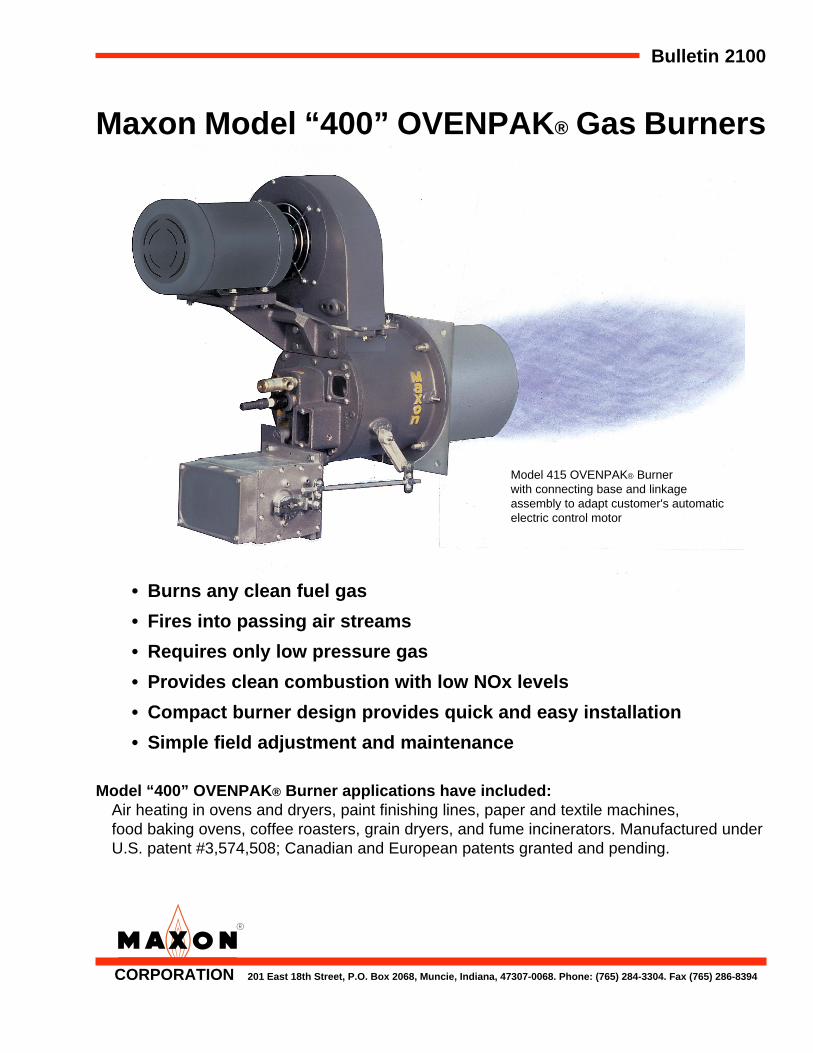
Bulletin 2100 Maxon Model “400” OVENPAK® Gas Burners • Burns any clean fuel gas • Fires into passing air streams • Requires only low pressure gas • Provides clean combustion with low NOx levels • Compact burner design provides quick and easy installation • Simple field adjustment and maintenance Model “400” OVENPAK® Burner applications have included: Air heating in ovens and dryers, paint finishing lines, paper and textile machines, food baking ovens, coffee roasters, grain dryers, and fume incinerators. Manufactured under U.S. patent #3,574,508; Canadian and European patents granted and pending. Model 415 OVENPAK® Burner with connecting base and linkage assembly to adapt customer's automatic electric control motor CORPORATION 201 East 18th Street, P.O. Box 2068, Muncie, Indiana, 47307-0068. Phone: (765) 284-3304. Fax (765) 286-8394
Transcript of Maxon Model “400” OVENPAK Gas Burners · Page 2106 Model “400” OVENPAK® Gas Burners Design...
Bulletin 2100
Maxon Model “400” OVENPAK® Gas Burners
• Burns any clean fuel gas
• Fires into passing air streams
• Requires only low pressure gas
• Provides clean combustion with low NOx levels
• Compact burner design provides quick and easy installation
• Simple field adjustment and maintenance
Model “400” OVENPAK® Burner applications have included:Air heating in ovens and dryers, paint finishing lines, paper and textile machines,food baking ovens, coffee roasters, grain dryers, and fume incinerators. Manufactured underU.S. patent #3,574,508; Canadian and European patents granted and pending.
Model 415 OVENPAK® Burnerwith connecting base and linkageassembly to adapt customer's automaticelectric control motor
CORPORATION 201 East 18th Street, P.O. Box 2068, Muncie, Indiana, 47307-0068. Phone: (765) 284-3304. Fax (765) 286-8394

Page 2102
Maxon Model “400” OVENPAK® Gas Burners
Model EB-3 OVENPAK® Burner withconnecting base and linkage assembly
Provide application flexibility with:• 40:1 turndown or more
• Over 90 different styles and sizes
• Heat releases to 16,500,000 Btu/hr
• Cost-effective external blower (EB) version
Typical piping layout with “Block and Bleed” gas train arrangement

Page 2103
Maxon Pre-Assembled PackageModel “400” OVENPAK® Gas Burner System
• A complete “packaged burner” system for maximum efficiency
• Pre-assembled system includes:
– High turndown Model “400” OVENPAK® Burner
– Completely assembled and pre-wired pipe train package
• Fast and easy installation with your choice of mounting options:
– Arranged for mounting onto your existing duct;
– Or mounted by Maxon in a pre-fabricated combustion heater/duct
Model 435OVENPAK®
Burner with pre-assembled “Block& Bleed” pipetrain and pre-wired intopackage system

Maxon Packaged Heater/Duct Sectionsfor Pre-Assembled OVENPAK® Gas Burner Systems
Model 425OVENPAK® Burnerpre-assembledpackage system,installed and mountedonto a Maxon pre-fabricated heater/ductsection
• Reduce your fabrication time and costly design details
• Easy mounting provided by flanged duct connection joints
• Application flexibility offered by:
– Three duct sizes
– Five capacity options
– Optional return/inlet duct opening positions
• Discharge air volumes up to 12,000 SCFM
• Handles discharge air temperatures up to 600°F (316°C)
Page 2104
12/89
CORPORATION 201 East 18th Street, P.O. Box 2068, Muncie, Indiana, 47307-0068. Phone: (765) 284-3304. Fax (765) 286-8394
Model “400” OVENPAK ® Gas Burner Page 2105
10/92
Design and Application Details
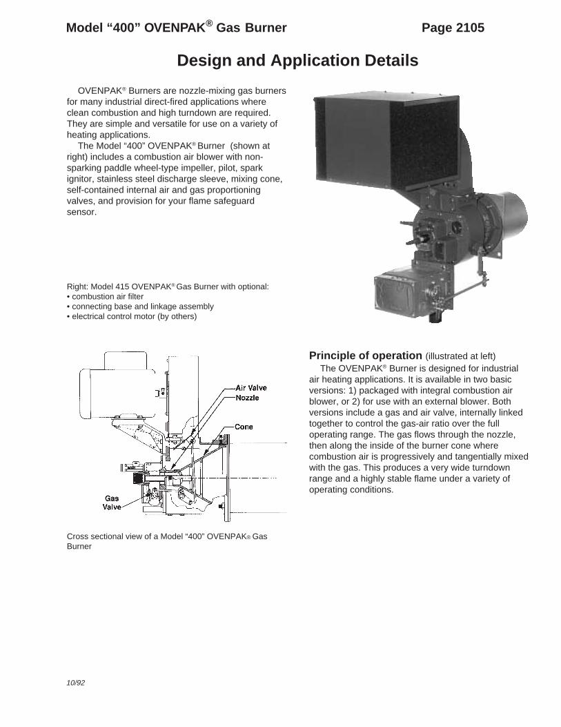
OVENPAK® Burners are nozzle-mixing gas burnersfor many industrial direct-fired applications whereclean combustion and high turndown are required.They are simple and versatile for use on a variety ofheating applications.
The Model “400” OVENPAK® Burner (shown atright) includes a combustion air blower with non-sparking paddle wheel-type impeller, pilot, sparkignitor, stainless steel discharge sleeve, mixing cone,self-contained internal air and gas proportioningvalves, and provision for your flame safeguardsensor.
Right: Model 415 OVENPAK® Gas Burner with optional:• combustion air filter• connecting base and linkage assembly• electrical control motor (by others)
Principle of operation (illustrated at left)The OVENPAK® Burner is designed for industrial
air heating applications. It is available in two basicversions: 1) packaged with integral combustion airblower, or 2) for use with an external blower. Bothversions include a gas and air valve, internally linkedtogether to control the gas-air ratio over the fulloperating range. The gas flows through the nozzle,then along the inside of the burner cone wherecombustion air is progressively and tangentially mixedwith the gas. This produces a very wide turndownrange and a highly stable flame under a variety ofoperating conditions.
Cross sectional view of a Model “400” OVENPAK® GasBurner
Page 2106 Model “400” OVENPAK ® Gas Burners
Design and Application Details
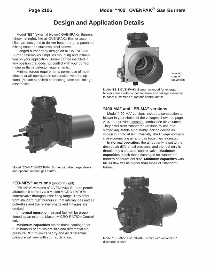
Model “EB” (external blower) OVENPAK® Burners(shown at right), like all OVENPAK® Burner assem-blies, are designed to deliver heat through a patentedmixing cone and stainless steel sleeve.
Flanged burner body design on all OVENPAK®
Burner assemblies simplifies mounting and installa-tion on your application. Burner can be installed inany position that does not conflict with your controlmotor or flame detector requirements.
Minimal torque requirements permit use of mostelectric or air operators in conjunction with the op-tional (Maxon supplied) connecting base and linkageassemblies.
Model EB-3 OVENPAK® Burner arranged for externalblower source with connecting base and linkage assemblyto adapt customer's automatic control motor
“400-MA” and “EB-MA” versionsModel “400-MA” versions include a combustion air
blower in your choice of the voltages shown on page2107, but provide constant combustion air volumes.They differ from “standard” versions by use of aslotted adjustable air butterfly locking device asshown in photo at left. Internally, the linkage normallycross-connecting air and gas butterflies is omitted.
In normal operation, the air butterfly is set to thedesired air differential pressure, and the fuel only isthrottled by a separate control valve. Maximumcapacities match those cataloged for “standard”burners of equivalent size. Minimum capacities withfull air flow will be higher than those of “standard”burner.
“EB-MRV” versions (photo at right)“EB-MRV” versions of OVENPAK® Burners permit
air/fuel ratio control via a Maxon MICRO-RATIO®
control valve throughout the firing range. They differfrom standard “EB” burners in that internal gas and airbutterflies and the related shafts and linkages areomitted.
In normal operation , air and fuel will be propor-tioned by an external Maxon MICRO-RATIO® Controlvalve.
Maximum capacities match those cataloged for“EB” burners of equivalent size and differential airpressure. Minimum capacity and air differentialpressure will vary with your application. Model “EB-MRV” OVENPAK® Burner with optional 12"
discharge sleeve
view intocone ofEB version
Model “EB-MA” OVENPAK® Burner with discharge sleeveand optional manual gas control

Page 2107Model “400” OVENPAK ® Gas Burners
Capacities and Specifications – 60 Hertz
5/93
Standard Model “400” OVENPAK ® Burner in-cludes a combustion air blower with motor.
Maximum capacity of Model “400” OVENPAK®
Burner is affected by the static pressure within thecombustion chamber. Data shown assumes firing inthe open, or into an airstream with enough oxygen tocomplete the combustion process. If burner is fired intoan oxygen-starved chamber or airstream, capacitiesmay be reduced as much as 25-30%. Do not attemptto operate beyond the duct static pressure rangeshown. For higher back pressure applications, selectfrom Model “EB” or “EB-MRV” OVENPAK® Burneroptions.
All gas pressures are differential pressures andare measured at the gas pressure test connection onthe backplate of each OVENPAK® Burner. Differentialpressures shown are approximate.
elbaliavAsegatloVrotoMzH06
rewopesroH epyT-802/51106/1/032
-80206/3/064/032
06/3/575
2/1&3/1yllatoT
desolcnEX X X
1&4/3yllatoT
desolcnEX X X
3&2,2/1-1yllatoT
desolcnEtoN
elbaliavAX X
–ataDgnitarepOdnaseiticapaC M224hguorht504ledoM
ledoMrenruB 504 M704 804 M804 M214 M314 514 M224
rotoMnoitacificepS
:rewopesroH 3/1 2/1 3/1 4/3 2/1 4/3 3/1 4/3
:rebmuNemarF 84 84 84 65 84 65 84 65
mumixaMseiticapaC
)rh/utBs'0001(saGlarutaNhtiw)cw"(serusserP
DUCT
STATICS
ot0.5-cw"5.0-
055"8.2
---088"4.3
-- --- ---0561"7.1
---
cw"0±005"3.2
057"5.2
008"8.2
097"7.2
0021"8.2
0031"3.3
0051"4.1
0512"9.2
cw"0.1+574"1.2
007"2.2
067"6.2
057"5.2
0011"4.2
0911"8.2
5241"3.1
0002"5.2
cw"0.2+054"9.1
006"6.1
027"3.2
046"8.1
529"7.1
0011"4.2
0531"1.1
5271"9.1
cw"0.3+ ---015"1.1
---055"3.1
008"3.1
0001"0.2
---0161"6.1
cw"0.4+ ---054"9.0
---594"1.1
057"1.1
009"6.1
---0051"4.1
cw"0.5+ --- --- ---574"0.1
---008"3.1
---0241"3.1
muminiMseiticapaC
)rh/utBs'0001(
tolipsulpniaM 51 02 73
ylnotoliP 01 51 02
laitnereffidsaglarutanderiuqeRerusserp )cw"(telnirenrubot
0.3 5.3 1.4 5.4 2.5 2.4 2.7
htgnelemalfetamixorppAriallitsni
.tf1ot2/1ot1
.tf2/1-1.tf1ot2/1 .tf2/1-2ot1
ot2/1-2.tf2/1-3
ot2/1-1.tf2

Page 2108 Model “400” OVENPAK ® Gas Burners
Capacities and Specifications – 60 Hertz
–ataDgnitarepOdnaseiticapaC M784hguorht524ledoM
ledoMrenruB 524 M234 534 M244 544 M654 M074 M784
rotoMnoitacificepS
:rewopesroH 4/3 4/3 4/3 1 1 2/1-1 2 3
:rebmuNemarF 65 65 65 65 65 T341 T541 T281
mumixaMseiticapaC
)rh/utBs'0001(saGlarutaNhtiw)cw"(serusserP
DUCT
STATICS
ot0.5-cw"5.0-
0572"7.2
---0583"2.2
---5715"4.3
0046"6.3
0508"7.3
06001"6.4
cw"0±0052"2.2
0023"6.3
0053"8.1
0514"5.2
0054"6.2
0065"8.2
0007"8.2
0078"4.3
cw"0.1+5732"0.2
0003"2.3
5233"6.1
0004"4.2
0824"3.2
0435"5.2
0756"5.2
0048"2.3
cw"0.2+0522"8.1
0082"8.2
0513"4.1
0083"1.2
5214"2.2
0025"4.2
0036"3.2
0028"0.3
cw"0.3+ ---0562"5.2
---0563"9.1
---0005"2.2
0055"7.1
0057"5.2
cw"0.4+ ---0052"2.2
---0053"8.1
---0064"9.1
0005"4.1
0026"7.1
cw"0.5+ ---0522"8.1
---0033"6.1
---0014"5.1
0054"2.1
0055"4.1
cw"0.6+ --- --- --- --- --- ---0053"7.0
0005"1.1
muminiMseiticapaC
)rh/utBs'0001(
tolipsulpniaM 06 78 011 521 051 571
ylnotoliP 53 54 09 501 511 711
laitnereffidsaglarutanderiuqeRerusserp )cw"(telnirenrubot
6.3 9.4 8.3 9.4 5.4 1.5 2.5 6.7
htgnelemalfetamixorppAriallitsni
.tf2/1-3ot2/1-2ot2/1-3
.tf5.tf5ot4 .tf6ot4 .tf7ot5 .tf8ot6 .tf01ot8

Page 2109Model “400” OVENPAK ® Gas Burners
Capacities and Specifications – 50 Hertz
8/00
Standard Model “400” OVENPAK ®
Burner includes a combustion air blowerwith motor.
Maximum capacity of Model “400”OVENPAK® Burner is affected by the staticpressure within the combustion chamber.Data shown assumes firing in the open, orinto an airstream with enough oxygen tocomplete the combustion process. If burneris fired into an oxygen-starved chamber orairstream, capacities may be reduced asmuch as 25-30%. Do not attempt to operatebeyond the duct static pressure rangeshown. For higher back pressure applica-tions, select from Model “EB” or “EB-MRV”OVENPAK® Burner options.
All gas pressures are differentialpressures and are measured at the gaspressure test connection on the backplateof each OVENPAK® Burner. Differentialpressures shown are approximate.
elbaliavAsegatloVrotoMzH05 )tsocartxetenelbissop(
rewopesroH epyT 05/1/002-091 05/3/514-083 05/3/005
2/1&3/1yllatoT
desolcnEX X X
1&4/3yllatoT
desolcnEX X X
3&2,2/1-1yllatoT
desolcnEX X X
-ataDgnitarepOdnaseiticapaC M224hguorht504ledoM
ledoMrenruB 504 M704 804 M804 M214 M314 514 M224
rotoMnoitacificepS
:rewopesroH 3/1 2/1 3/1 4/3 2/1 4/3 3/1 4/3
:rebmuNemarF 84 84 84 65 84 65 84 65
mumixaMseiticapaC
)rh/utBs'0001(saGlarutaNhtiw)cw"(serusserP
DUCT
STATICS
cw"0.5-064"0.2
---537"4.2
--- --- ---5731"2.1
---
cw"0.3-064"0.2
---537"4.2
--- --- ---5731"2.1
---
cw"0±514"6.1
526"7.1
076"0.2
066"9.1
0001"0.2
0801"5.2
0521"0.1
0081"0.2
cw"0.1+093"4.1
585"5.1
036"7.1
526"7.1
029"7.1
099"4.2
0911"9.0
0761"8.1
cw"0.2+ --- --- --- --- ---029"7.1
---0441"3.1
muminiMseiticapaC
)rh/utBs'0001(
tolipsulpniaM 51 02 51 02 73
ylnotoliP 01 51 02
laitnereffidsaglarutanderiuqeRerusserp )cw"(telnirenrubot
2.2 3.2 0.3 6.2 5.3 1.4 9.2 6.5
htgnelemalfetamixorppAriallitsni
.tf1ot2/1ot1
.tf2/1-1.tf1ot2/1 .tf2ot1
ot2/1-1.tf2
ot2.tf2/1-2

Page 2110 Model “400” OVENPAK ® Gas Burners
Capacities and Specifications – 50 Hertz
-ataDgnitarepOdnaseiticapaC M784hguorht524ledoM
ledoMrenruB 524 M234 534 M244 544 M654 M074 M784
rotoMnoitacificepS
:rewopesroH 4/3 4/3 4/3 1 1 2/1-1 2 3
:rebmuNemarF 65 65 65 65 65 T341 T541 T281
mumixaMseiticapaC
)rh/utBs'0001(saGlarutaNhtiw)cw"(serusserP
DUCT
STATICS
cw"0.5-0032"9.1
---0292"3.1
---5234"4.2
0535"5.2
0076"6.2
0048"2.3
cw"0.3-0032"9.1
---0292"3.1
---5234"4.2
0535"5.2
0076"6.2
0048"2.3
cw"0±0902"6.1
0762"5.2
0872"1.1
0643"8.1
0673"8.1
0764"9.1
0585"0.2
0527"3.2
cw"0.1+0791"4.1
0432"0.2
---0433"6.1
---0544"8.1
0055"7.1
0507"1.2
cw"0.2+ --- --- ---0223"5.1
---0434"7.1
0525"6.1
0586"1.2
cw"0.3+ --- --- --- --- --- --- ---0526"7.1
muminiMseiticapaC
)rh/utBs'0001(
tolipsulpniaM 06 78 011 521 051 571
ylnotoliP 53 54 09 501 511 711
laitnereffidsaglarutanderiuqeRerusserp )cw"(telnirenrubot
5.2 8.3 2.2 8.3 1.3 6.3 0.5 0.5
htgnelemalfetamixorppAriallitsni
.tf3ot2ot3
.tf2/1-4ot2/1-3
.tf4.tf5ot4 .tf6ot5 .tf8ot7

Page 2111Model “400” OVENPAK ® Gas Burners
12/92
Capacities and SpecificationsExternal Blower (EB) versions
1-BEKAPNEVO ®
renruB
dnanoitsubmoCriAgnilooC
deriuqer
)cw"(erusserPriAlaitnereffiD 3 4 5 6 8 9 01 11
)MFCS(emuloV 051 071 091 012 042 552 072 082
sesaeleRtaeH)rh/utBs'0001(
yticapaCmumixaM 064 085 517 087 078 019 069 0001
tolip&muminiM 06 06 06 06 06 06 06 06
ylnotoliP 54 54 54 54 54 54 54 54
saGlarutaNlaitnereffid
serusserp )cw"(
telnirenrubtA 1.2 4.3 1.5 1.6 6.7 3.8 2.9 0.01
noitcennoctsetsagrenrubtA 0.2 1.3 7.4 6.5 0.7 6.7 5.8 2.9
shtgneLemalF riallitsnI eveelsegrahcsidfodnednoyeb"51ot"4
2-BEKAPNEVO ®
renruB
dnanoitsubmoCriAgnilooC
deriuqer
)cw"(erusserPriAlaitnereffiD 3 4 5 6 8 9 01 11
)MFCS(emuloV 022 052 082 013 553 573 593 514
sesaeleRtaeH)rh/utBs'0001(
yticapaCmumixaM 057 089 0021 0331 0541 0051 0551 0061
tolip&muminiM 06 06 06 06 07 07 57 08
ylnotoliP 52 52 52 52 03 03 53 53
saGlarutaNlaitnereffid
serusserp )cw"(
telnirenrubtA 3 2.5 8.7 5.9 3.11 1.21 9.21 8.31
noitcennoctsetsagrenrubtA 5.2 2.4 3.6 7.7 2.9 8.9 5.01 2.11
shtgneLemalF riallitsnI eveelsegrahcsidfodnednoyeb"03ot"21
3-BEKAPNEVO ®
renruB
dnanoitsubmoCriAgnilooC
deriuqer
)cw"(erusserPriAlaitnereffiD 3 4 5 6 8 9 01 11
)MFCS(emuloV 053 504 554 594 575 516 056 576
sesaeleRtaeH)rh/utBs'0001(
yticapaCmumixaM 0261 0091 0212 0232 0762 0482 0003 0513
tolip&muminiM 09 59 501 511 031 041 051 551
ylnotoliP 54 54 05 55 56 07 57 57
saGlarutaNlaitnereffid
serusserp )cw"(
telnirenrubtA 1.4 6.5 0.7 3.8 0.11 5.21 9.31 4.51
noitcennoctsetsagrenrubtA 6.1 2.2 8.2 3.3 4.4 0.5 6.5 2.6
shtgneLemalF riallitsnI eveelsegrahcsidfodnednoyebteef3ot2
4-BEKAPNEVO ®
renruB
dnanoitsubmoCriAgnilooC
deriuqer
)cw"(erusserPriAlaitnereffiD 3 4 5 6 8 9 01 11
)MFCS(emuloV 055 536 017 577 598 059 0001 0501
sesaeleRtaeH)rh/utBs'0001(
yticapaCmumixaM 0232 0082 0323 0053 0593 0514 0334 0064
tolip&muminiM 001 511 031 041 061 071 081 091
ylnotoliP 04 04 04 54 05 55 55 06
saGlarutaNlaitnereffid
serusserp )cw"(
telnirenrubtA 5.2 7.3 9.4 8.5 4.7 1.8 8.8 0.01
noitcennoctsetsagrenrubtA 9.1 8.2 7.3 3.4 5.5 1.6 6.6 5.7
shtgneLemalF riallitsnI eveelsegrahcsidfodnednoyebteef2/1-3ot2/1-2

Page 2112 Model “400” OVENPAK ® Gas Burners
Capacities and SpecificationsExternal Blower (EB) versions
5-BEKAPNEVO ®
renruB
dnanoitsubmoCriAgnilooC
deriuqer
)cw"(erusserPriAlaitnereffiD 3 4 5 6 8 9 01 11
)MFCS(emuloV 566 077 068 049 0801 0511 0121 0721
sesaeleRtaeH)rh/utBs'0001(
yticapaCmumixaM 0492 0053 0893 0244 0315 0545 0475 0006
tolip&muminiM 551 081 002 022 552 072 582 003
ylnotoliP 52 03 53 53 04 54 05 05
saGlarutaNlaitnereffid
serusserp )cw"(
telnirenrubtA 2.2 1.3 0.4 9.4 6.6 5.7 3.8 1.9
noitcennoctsetsagrenrubtA 3.1 8.1 3.2 9.2 9.3 4.4 8.4 3.5
shtgneLemalF riallitsnI eveelsegrahcsidfodnednoyebteef5ot3
6-BEKAPNEVO ®
renruB
dnanoitsubmoCriAgnilooC
deriuqer
)cw"(erusserPriAlaitnereffiD 3 5 8 11 61 81 22 42
)MFCS(emuloV 579 0621 0951 0781 0522 0932 0462 0672
sesaeleRtaeH)rh/utBs'0001(
yticapaCmumixaM 0174 0076 0059 00211 00531 00341 00851 00561
tolip&muminiM 533 093 094 575 596 537 518 058
ylnotoliP 001 001 001 511 041 541 561 071
saGlarutaNlaitnereffid
serusserp )cw"(
telnirenrubtA 8.2 6.5 3.11 7.51 8.22 6.52 3.13 1.43
noitcennoctsetsagrenrubtA 0.2 0.4 1.8 2.11 3.61 3.81 3.22 3.42
shtgneLemalF riallitsnIfodnednoyebteef8ot3
eveelsegrahcsidfodnednoyebteef21ot8
eveelsegrahcsid
7-BEKAPNEVO ®
renruB
dnanoitsubmoCriAgnilooC
deriuqer
)cw"(erusserPriAlaitnereffiD 3 5 8 11 61 81 22 42
)MFCS(emuloV 579 0621 0951 0781 0522 0932 0462 0672
sesaeleRtaeH)rh/utBs'0001(
yticapaCmumixaM 0174 0076 0059 00211 00531 00341 00851 00561
tolip&muminiM 533 093 094 575 596 537 518 058
ylnotoliP 001 001 001 511 041 541 561 071
saGlarutaNlaitnereffid
serusserp )cw"(
telnirenrubtA 8.1 6.3 3.7 1.01 8.41 6.61 2.02 1.22
noitcennoctsetsagrenrubtA 0.1 0.2 1.4 6.5 2.8 2.9 2.11 2.21
shtgneLemalF riallitsnIfodnednoyebteef8ot3
eveelsegrahcsidfodnednoyebteef21ot8
eveelsegrahcsid
Page 2113Model “400” OVENPAK ® Gas Burners
Accessory Options
6/96
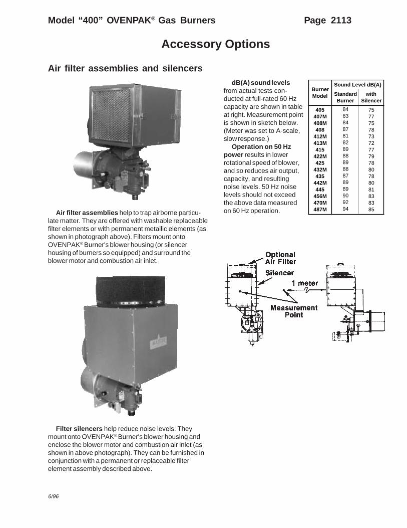
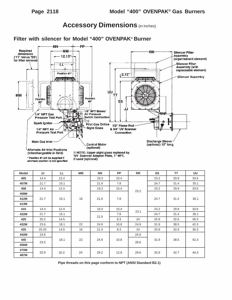
Air filter assemblies and silencersdB(A) sound levels
from actual tests con-ducted at full-rated 60 Hzcapacity are shown in tableat right. Measurement pointis shown in sketch below.(Meter was set to A-scale,slow response.)
Operation on 50 Hzpower results in lowerrotational speed of blower,and so reduces air output,capacity, and resultingnoise levels. 50 Hz noiselevels should not exceedthe above data measuredon 60 Hz operation.Air filter assemblies help to trap airborne particu-
late matter. They are offered with washable replaceablefilter elements or with permanent metallic elements (asshown in photograph above). Filters mount ontoOVENPAK® Burner's blower housing (or silencerhousing of burners so equipped) and surround theblower motor and combustion air inlet.
Filter silencers help reduce noise levels. Theymount onto OVENPAK® Burner's blower housing andenclose the blower motor and combustion air inlet (asshown in above photograph). They can be furnished inconjunction with a permanent or replaceable filterelement assembly described above.
BurnerModel
Sound Level dB(A)
StandardBurner
withSilencer
405407M408M408
412M413M415
422M425
432M435
442M445
456M470M487M
84838487818289888988878989909294
75777578737277797880788081838385

Page 2114 Model “400” OVENPAK ® Gas Burners
Accessory Options
Auxiliary SwitchesMaxon offers 4 types, all cam-actuated by the
burner main operating shaft. (If Universal Joint Ar-rangements are used, switch must mount on furthestleft burner.) Field installation MAY require burnermodification per instructions provided in ProductInformation Sheet 2000-7/8.
Low Fire Start Switch Assembly (SPDT) opensthe circuit when burner leaves minimum position. Alsoavailable in Weatherproof and Hazardous Location/Weatherproof versions.
High and Low Fire Position Switch Assemblyincludes 2 SPDT switches. One switch may be field-set to activate at high fire position, while other is set toactivate at low fire position. Switch assemblies arealso available in a weatherproof version.
Universal Joint Arrangements (for allversions except EB-MRV) allow control of as many as5 burners by a single control motor. Torque require-ment is 10 in-lbs for EACH burner driven. Primaryburner should drive no more than 2 Secondary burnersto either side of itself.
Miniature universal joints simplify burner alignment.Aluminum connecting rod can be cut to fit actualburner spacing. (Allowable distance between adjacentburner centerlines is 21" – 33" for 422M and smaller,23.5" – 36" for larger burners.)
To order, specify:1. Primary and secondary burners2. Any other accessories desired3. Required quantity of Universal Joint Assemblies
Manual Handle Kit permits setting and lockingair and fuel valves at a constant firing rate. See photobelow.
Discharge Sleeve Mounting GasketsStandard discharge sleeve gasket provides
adequate sealing in most applications.High Back Pressure Gasket Kit includes 2 addi-
tional gaskets to provide sealing against back pres-sures as shown in sketch below.
WithHigh Back Pressure Kit
StandardArrangement
Low Fire Start Switch shown

Page 2115
Accessory Options
Model “400” OVENPAK ® Gas Burners
9/94
Discharge Sleeves are available in 3 versions:
– Standard sleeve is 8" long, made of #310 SS, andis suitable for downstream temperatures up to1000°F (538°C).
– For higher velocities , specify 12" long sleeve madeof #310 SS for downstream temperatures up to1000°F (538°C).
– For higher downstream temperatures between1000°F (538°C) and 1500°F (816°C), specify 8" long,#RA 330 SS sleeve.
Hi/Lo Control Motor Sets for high or low firing.Optional set includes 2-position unidirectional 11-second 120v 50/60 Hz motor and connecting base withmounting linkage. See table below for dimensionswhich differ from standard burner.
ledoMrenruBsehcnInisnoisnemiD
P R T
2,1-BE M314-504 52.01 36.71 57.7
3-BE M224-514 91.01 65.71 57.7
5,4-BE M244ot524 96.11 60.91 57.8
7,6-BE M784-544 96.61 60.42 57.8

Page 2116 Model “400” OVENPAK ® Gas Burners
Dimensions (in Inches)
Model “400” and “400-MA” OVENPAK ® Burners
Pipe threads on this page conform to NPT (ANSI Standard B2.1)
NOTE: Use of auxiliary switches will add to dimension D.
ledoM A *B C D E F G H J K L M N CC DD EE FF GG HH JJ KK
504
57.3 1
44.5
26.6 78.8 03.01
91.31
44.8
73.4
13.6 44.8 26.3
52.0
18.8 73.11 41 66.313.71
18.71 73.41 60.71
M704 52.51 78.51 81 96.4 96.91 96.12 26.81
804 18.8 73.11 41 66.3 21.91 18.71 73.41 60.71
M804
52.51 78.51 81 96.413.71
96.91 96.12 26.81M214
M314 21.91
51457.4 4/1-1 96.7 18.8 52.01 73.01 52.8 73.01 44.4
18.8 73.11 4195.3 13.71
57.71 73.41 60.71
M224 52.51 78.51
81
65.91 96.12 26.81
524
57.5
2/1-1
60.6 26.8
60.01 88.11 96.41 05.21 44.5 52.01 5.21 26.5
73.0
21.21 44.41 49.3
52.81
5.02 52.02 57.91
M234
2
52.51 78.51 18.2 52.12 65.32 26.92
534 21.21 44.41 49.3 5.02 52.02 57.91
M244
52.51 78.51
18.2 52.12 65.32
26.92
544
18.6 83.41 88.61 13.91 26.41 5.6 52.21 57.41 96.6 73.5
5.2252 5.32
M654
42M0743 57.71 97.71 91 18.62 49.52
M784
TPNtelnisagleufniaM*

Page 2117Model “400” OVENPAK ® Gas Burners
10/03
Dimensions (in Inches)
Model EB, EB-MA, and EB-MRV OVENPAK ® Burners
Pipe threads on this page conform to NPT (ANSI Standard B2.1)
NOTE: Use of auxiliary switches will add to dimension D.
ledoM A B C D E F G H J K L M N U V W X Y AA BB
1-BE57.3
4/1-1 44.526.6
78.8 13.01 91.3144.8
73.413.6 44.8 26.3
52.0 52.7 26.8 73.6 44.0 44.544.5
42-BE
3-BE 57.4 96.7 73.01 52.8 73.01 44.4 83.5
4-BE57.5 2
60.6 26.8
60.01 88.11 96.41 5.21 44.5 52.01 5.21 26.5
73.0
52.9 26.01 78.8
65.0
57.7 6 65-BE
6-BE18.6 3 83.41 88.61 13.91 26.41 5.6 52.21 57.41 96.6 26.9 21.11
-7.115
52.01 5.8 87-BE
A
B C
45˚
22.5˚
D dia.
.562 dia.8 holes
renruBeziS
A B C .aidD
M314-5042BE,1BE
83.8 31.01 60.41 36.21
M224,5143BE
83.8 0.21 49.51 5.41
M244-5245BE,4BE
83.8 60.41 0.81 35.61
M784-5447BE,6BE
83.8 60.61 0.02 35.81
Refractory Lined Discharge Sleeve
Page 2118 Model “400” OVENPAK ® Gas Burners
Accessory Dimensions (in Inches)
Filter with silencer for Model “400” OVENPAK ® Burner
Pipe threads on this page conform to NPT (ANSI Standard B2.1)
ledoM JJ LL MM NN PP RR SS TT UU
504 4.41 4.21
61
3.91 4.01
2.32
2.32 9.92 6.33
M704 7.12 1.51 9.12 8.7 7.42 4.13 1.53
804 4.41 4.21 3.91 4.01 2.32 9.92 6.33
M804
7.12 1.51 9.12 8.7 7.42 4.13 1.53M214
M314
514 4.41 4.21 3.91 4.011.32
2.32 9.92 6.33
M224 7.12 1.519.12
8.7 7.42 4.13 1.53
524 2.02 5.41 3.8 42 9.52 6.23 3.63
M234 6.32 1.81 22 9.42 8.01 9.42 9.13 5.83 3.24
534 52.02 5.41 61 4.12 3.8 42 9.52 6.23 3.63
M244 6.32
1.81 22 9.42 8.01
9.42
9.13 5.83 3.245445.32 6.82
M654
M0749.52 2.02 42 2.92 8.21 6.92 9.33 7.24 3.44
M784

Page 2119Model “400” OVENPAK ® Gas Burners
Component Identification
9/03
Suggested spare parts– Spark Ignitor – Discharge Sleeve and Gasket– Flame Rod, if used – Motor– Filter Elements, if used – Impeller– Mixing Cone – Gas/Air Valve Linkage KitTo order parts for an existing OVENPAK® Burner assembly, list:1. Name(s) of part(s) from above illustration2. Quantity of each required3. OVENPAK® Burner nameplate information:
• size and model number of burner• assembly number• date of manufacture• if available, serial number of Maxon fuel shut-off valve in-line to OVENPAK®
Burner (This serial number is on Maxon valve's nameplate.)
Nameplate

Page 2120 Model “400” OVENPAK ® Gas Burners
Suggested Maintenance/Inspection Procedures
Discharge sleeve and cone alignmentCentering of the mixing cone provides a small
annular opening for the flow of some cooling combus-tion air along the discharge sleeve wall. We SUGGESTperiodic inspection from the discharge side of theburner to assure that this alignment is maintained.
Caution: Tightening can lead to cone distortionand greatly reduce cone and discharge sleevelife. Cone should be free to move and allow forthermal expansion.
If re-adjustment is necessary, back out the four locknuts and re-center mixing cone with adjusting screwshandtight. Back each screw out one-half turn before re-locking. This allows for thermal expansion as conegets hot.
Filters should be inspected regularly and cleaned,using a vacuum to remove loose/dry accumulations,then washing and/or degreasing as appropriate for thefilter type used.
To replace flame rod or spark ignitor:1. Check Table 1 at right for dimension “Y” and cut tip
to length shown.2. Insert 1/2" NPT collar into burner and snug into
position.3. Insert insulator through collar into burner.4. Check table for dimension “X”, position accordingly,
and tighten locking bushing until insulator is heldfirmly.
WARNING: Over-tightening locking bushing maydamage insulator.
NOTE: A full-wave 6000 volt spark ignition transformeris suggested for use with Maxon burner equipment.
Flame Rod
NOTE: 1/2" x 1" adapter bushing supplied by others
Table 1: Flame rod and spark ignitor dimensionsfor all Model “400” OVENPAK ® Burnersmanufactured after 1/1/91 ①
① Manufactured date is stamped on metal nameplateof Model “400” OVENPAK® Burner. For specificsrelative to units manufactured prior to 1/1/91, seeProduct Information Sheet 2100-3.
ledoMrenruB
rotingIkrapSsnoisnemiD
doRemalFsnoisnemiD
X Y X Y Z
1-BE2-BE
504
3.1 4.
4. 6 9.2
M704
M804
804
M214
M314
3-BE514
5.1 4.M224
4-BE5-BE
524
2.1 4. 8. 8.01 5.3M234
534
M244
6-BE7-BE
544
3.1 4. 4. 8.21 9.2M654
M074
M784

Page 2121Model “400” OVENPAK ® Gas Burners
Maxon Pre-Assembled PackageModel “400” OVENPAK ® Gas Burner System
6/03
425 OVENPAK®
package systeminstalled andmounted onto aMaxonpre-fabricatedheater/duct section
Save time and reduce your installation costs with acompletely assembled and pre-wired burner and pipetrain “package”.
All system components have been carefully se-lected to match the high performance characteristics ofthe Model “400” OVENPAK® Gas Burner.
The compact design of this “packaged system”makes mounting to your duct fast and easy. Connectto the gas line and bring in electricity. It's wired andpiped, ready to go.
All pre-assembled package systems include aModel “400” OVENPAK® Burner and pipe train. Thepipe trains are available with “Block and Bleed” ar-rangement options only.
Additional application flexibility is provided with fivedifferent sized systems, all with 40:1 turndowncapacity ranges.
Packaged OVENPAK® Burner systems may also bemounted in a pre-fabricated combustion heater/ductsection by Maxon. This option is value-engineered togive you the most for your dollar spent.

Page 2122 Model “400” OVENPAK ® Gas Burners
Design / Application Summary
Five Model "400" OVENPAK ® pre-assembled package options:
Pre-assembled pipe train “package”includes the following components:– Burner gas shut-off cock– Main inlet gas shut-off cock– Pilot gas train consisting of:
• Pilot gas shut-off cock• Pilot gas pressure regulator (maximum 1 PSIG
natural gas inlet pressure)• Pilot gas solenoid valve, 115/60VAC
– Main gas pressure regulator (maximum 1 PSIGnatural gas inlet pressure)
– Combustion air pressure switch, automatic reset,NEMA 1, 115/60VAC
– Combination high and low gas pressure switch,manual reset, NEMA 1, 115/60VAC
– Spark ignition transformer, 6000 volts, NEMA 1, 115/60VAC
– NEMA type 12 and 13 junction box with terminalwiring strip
– Normally open vent solenoid valve, 115/60VAC
A complete packaged system also includes:• Maxon Model “400” OVENPAK® Burner assembly
– Connecting base and linkage assembly to adaptcustomer-supplied automatic control motor(optional)
– Low fire start switch (mounted to OVENPAK®
Burner)– Air filter assembly
• Maxon main gas shut-off valve, position “L”, 115/60VAC
• Maxon main gas “blocking” shut-off valve, position“L”, 115/60VAC00000000
Factory pre-wiring includes the followingcomponents for 115 volts 60 hertz AC:– Low fire start switch– Combustion air pressure switch– Combination high and low gas pressure switch– Pilot gas solenoid valve– Normally-open vent solenoid valve (when used)– Spark ignition transformer– Maxon “main” and/or “blocking” gas shut-off valve(s)– NEMA type 12 and 13 junction box with terminal
wiring strip
Field wiring is required:– To the packaged system's junction box wiring strip– To the Model “400” OVENPAK® Burner's combustion
air blower motor– Between your flame safeguard relay and the
OVENPAK® Burner's flame sensorNOTE: A flame rod may be furnished by Maxon; UVdetector is a part of the control package whensupplied by Maxon or may be supplied by others.
– Other field wiring connections may be required if yourcontrol circuit includes high/low temperature limits,automatic temperature controller, and/or othermiscellaneous safety limit switches.
KAPNEVO ® >ledoMrenruB 504 804 514 524 534
rotoMrewolBdesolcnEyllatoTrewopesroH 3/1 4/3
rebmuNemarF 84 65
yticapaCmumixaM )rh/utB( 000,005 000,008 000,005,1 000,005,2 000,005,3
yticapaCmuminiM tolipsulpniam)rh/utB( 000,51 000,02 000,73 000,06 000,78
erusserpsaglarutanmuminiM telniniartepiptaderiuqer cw"6 cw"01 cw"9 cw"41
ezisniartepiptelnI TPN "52.1 "5.1
snoisnemidepolevnellarevoetamixorppA ediw"42xhgih"04xgnol"24

Page 2123Model “400” OVENPAK ® Gas Burners
Maxon Packaged Heater/Duct Sections
Reduce your fabrication time with a completecombustion heater/duct including the prewired andprepiped Model “400” OVENPAK® Burner systempackage.
Easy installation is provided by flanged ductconnection joints. Burner is mounted to a .312" mildsteel wall, lined with 6" thick fiber insulation. The other16 gauge aluminized steel heater/duct walls are readyfor your insulation.
Application flexibility is offered by three sizes ofducts. All sizes can be fabricated to have return/inletopening at any 90° increment position (viewing fromthe back of the OVENPAK® Burner). Continuous weldson all joint seals permit duct section installation onpressure-side or suction-side applications.
6/03
snoisnemidnoitcestcudetamixorppA )sehcnini(ledoM A B )edisni( C D )edisni( E F G H J )edisni( K
804-504 21 42 5 01 63 84 26.21 26.62 5.7 73
514 51 03 6 21 24 06 26.41 26.23 5.9 84
534-524 81 63 8 61 84 27 26.81 26.83 5.11 85

Page 2124 Model “400” OVENPAK ® Gas Burners
Maxon Packaged Heater/Duct SectionsDesign and Application Details
Maximum discharge temperature 600°F (316°C)Duct static pressures may range between +2" wc and -5" wcOptimum design parameters permit up to 3000 feet per minute air velocity through return/inlet duct.
To select your packaged system, specify:
1. Quantity ________
2. Model “400” OVENPAK ® Gas Burner Assembly _________, for natural gas– Arranged for UV detector, or with flame rod– Furnished with blower motor for ___________ AC– With low fire start switch _________ , General Purpose, 115/60 AC– With combustion air filter assembly ____________ (optional)– With connecting base and linkage assembly ____________ to adapt customer's automatic electric
control motor. Specify/select which one of these electric operators will be used:– Barber-Colman #EA51–58, also with prefix MC, MP or MF– Honeywell #M644, #M744, #M941, or #M944– Penn/Johnson #M-80 or #M81
3. Arranged into pre-assembled and wired pipe train package, 115/60VAC,– With Block and Bleed arrangement assembly ______________.
4. With _______ 1-1/4" or 1-1/2" Maxon Series __________ Automatic Reset, Manual ResetShut-Off Valve (s), for natural gas, in top assembly position “L” for 115/60VAC– With electrical terminal block (option)– With 6 second, or 2.5 second opening time (automatic reset valve(s) only)– With ______________ auxiliary signal switch(es) (optional)
NOTE: Specify which switch(es) go in main valve and which switch(es) in blocking valve, if different.
5. With heater/duct section assembly ____________ (optional)with return/inlet duct positioned on top, right, bottom, or left
semulovriaegrahcsidmumixamdednemmoceRKAPNEVO"004"ledoM ® renruB 504 804 514 524 534
emulovriaegrahcsidmumixaM MFCSni 0005 0057 000,21

Page 2125Model “200” OVENPAK ® Gas Burners
12/89
Model “200” OVENPAK ® Burners
Model “200” OVENPAK® Gas Burnersprovide a broad range of heat without acombustion blower by firing through-the-wallinto your combustion chamber on the suctionside of the circulating fan. An internal mixingcone blends air drawn through the burner (bychamber suction) with fuel gas deliveredthrough its central gas nozzle. The Model“200” OVENPAK® Burner is designed forapplications involving suction-side firing from -0.2" to -1.6" wc static chamber conditions.They provide:– low initial and operating cost– easy installation– simple adjustment– heavy duty cast iron construction in a
compact burner configuration
Performance dataNOTE: Maximum capacity varies with the range of suction provided at operating temperature
Air volumes shown are for burners without damper,or with damper in full-open position. If damper is usedto restrict air flow, maximum capacity will be similarlyreduced.
Pilot flame issues from the same gas ports asmain flame, so proof of pilot gas ignition assuresignition of main gas supply.
Flame sensing can be either by flame rod or UVscanner when natural gas is the fuel, but only with UVscanner if propane is the fuel.
Installation is simple, utilizing the built-in, direct-mounting flange provided.
A complete combustion system utilizing Model“200” OVENPAK® Burners also includes gas train,fuel-throttling valve and control system. Your Maxonrepresentative can help you choose from the broadrange of options available.
Typical pipe train
Model “200” OVENPAK®
Burner arranged with air inletguard and optional UV scanner
atadecnamrofrePseiticapacmumixaM laitnereffidsagleufgnidnopserrochtiw)rh/utBs'0001(
snoitidnocerusserpcitatsrebmahcnoitsubmoccificepstaserusserp
noitcusrebmahcnoitsubmoC )cw"( 2.0- 3.0- 4.0- 5.0- 6.0- 7.0- 8.0- 9.0- 0.1- 6.1-
yticapacmumixaM )rh/utBs'0001( 001 091 572 063 054 045 526 007 008 0001
yticapacmuminiM )rh/utBs'0001( 01 21 31 41 51 71 81 91 02 52
emulovrianoitsubmoC )MFCS(deriuqer 56 08 09 59 011 021 031 531 541 481
erusserplaitnereffidsaglarutaN )cw"(deriuqer 1.0 4.0 7.0 2.1 9.1 7.2 7.3 6.4 0.6 4.9
erusserplaitnereffidsagenaporP )cw"(deriuqer --- --- 3.0 5.0 8.0 1.1 5.1 8.1 4.2 8.3
shtgnelemalfetamixorppA fodnednoyeb)sehcni(eveelsegrahcsid
3-0 9-6 81-21 12-51 42-81 72-12 03-42 62-42

Page 2126 Model “200” OVENPAK ® Gas Burners
Design and Application Details
Differential gas pressures in inches water column(" wc) for both natural gas and propane are those thatshould be measured by connecting a manometerbetween test points shown in the photo below.
Suction (shown in inches wc) should be thatavailable at operating temperature. It can be deter-mined by a two-step procedure: First, measure coldsuction (chamber to atmosphere). Second, multiplythat reading by the correction factor shown in Graph"A" for your desired operating temperature.
Dimensions (in inches)
BurnerAssembly
Flame Rod Assembly
Model “208” OVENPAK® Burner shown with air damperand flame rod For example, if you anticipate running the system at 600°F,
follow that dotted line to the right until it intersects curve,then read downward to a correction factor of 0.5. Therefore,if you read a cold suction of 1" wc, your expected suction“at temperature” would be 1" x 0.5 = 0.5" wc.
mCORPORATIONMUNCIE, INDIANA, USAINDUSTRIAL COMBUSTION EQUIPMENT AND VALVES
Maxon practices a policy of continuous product improvement. It reserves the right to alter specifications without prior notice.
Page 2100-S-1“400”, “200” OVENPAK® Burners
Installation Instructions
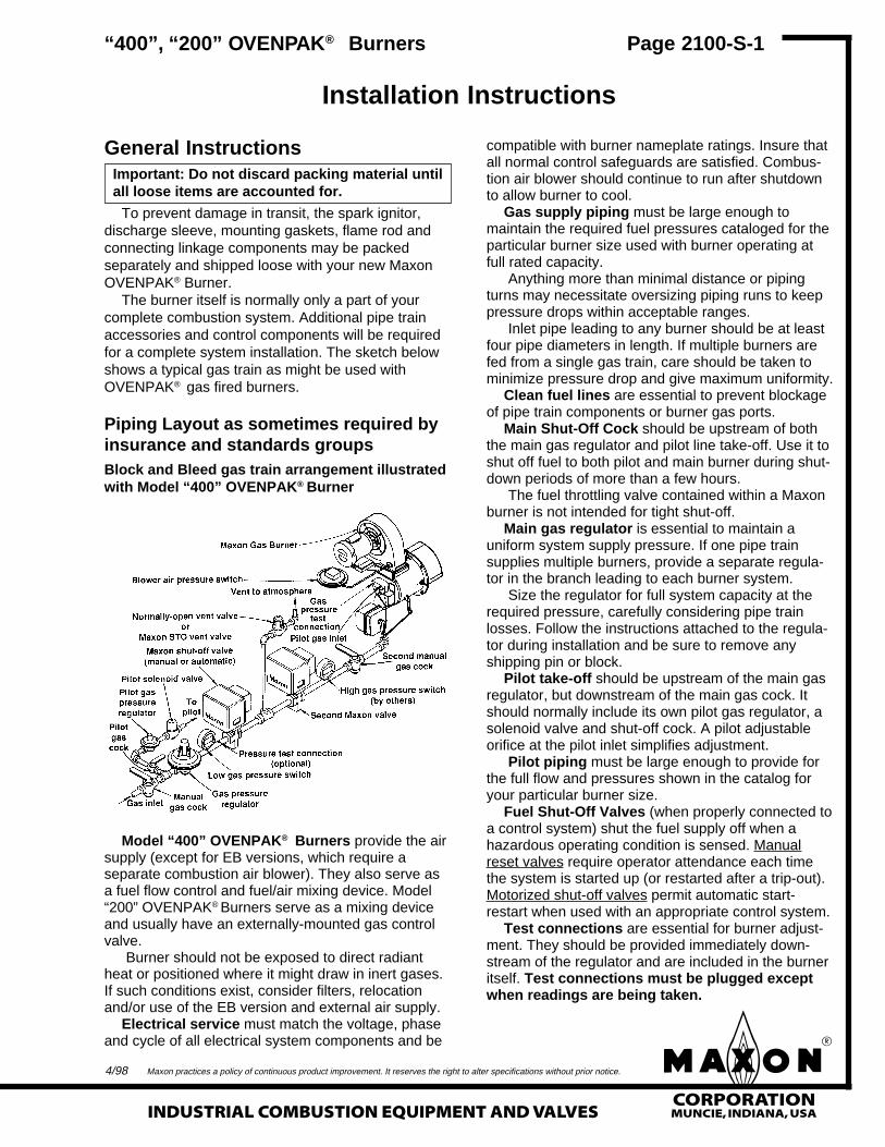
General InstructionsImportant: Do not discard packing material untilall loose items are accounted for.
To prevent damage in transit, the spark ignitor,discharge sleeve, mounting gaskets, flame rod andconnecting linkage components may be packedseparately and shipped loose with your new MaxonOVENPAK® Burner.
The burner itself is normally only a part of yourcomplete combustion system. Additional pipe trainaccessories and control components will be requiredfor a complete system installation. The sketch belowshows a typical gas train as might be used withOVENPAK® gas fired burners.
compatible with burner nameplate ratings. Insure thatall normal control safeguards are satisfied. Combus-tion air blower should continue to run after shutdownto allow burner to cool.
Gas supply piping must be large enough tomaintain the required fuel pressures cataloged for theparticular burner size used with burner operating atfull rated capacity.
Anything more than minimal distance or pipingturns may necessitate oversizing piping runs to keeppressure drops within acceptable ranges.
Inlet pipe leading to any burner should be at leastfour pipe diameters in length. If multiple burners arefed from a single gas train, care should be taken tominimize pressure drop and give maximum uniformity.
Clean fuel lines are essential to prevent blockageof pipe train components or burner gas ports.
Main Shut-Off Cock should be upstream of boththe main gas regulator and pilot line take-off. Use it toshut off fuel to both pilot and main burner during shut-down periods of more than a few hours.
The fuel throttling valve contained within a Maxonburner is not intended for tight shut-off.
Main gas regulator is essential to maintain auniform system supply pressure. If one pipe trainsupplies multiple burners, provide a separate regula-tor in the branch leading to each burner system.
Size the regulator for full system capacity at therequired pressure, carefully considering pipe trainlosses. Follow the instructions attached to the regula-tor during installation and be sure to remove anyshipping pin or block.
Pilot take-off should be upstream of the main gasregulator, but downstream of the main gas cock. Itshould normally include its own pilot gas regulator, asolenoid valve and shut-off cock. A pilot adjustableorifice at the pilot inlet simplifies adjustment.
Pilot piping must be large enough to provide forthe full flow and pressures shown in the catalog foryour particular burner size.
Fuel Shut-Off Valves (when properly connected toa control system) shut the fuel supply off when ahazardous operating condition is sensed. Manualreset valves require operator attendance each timethe system is started up (or restarted after a trip-out).Motorized shut-off valves permit automatic start-restart when used with an appropriate control system.
Test connections are essential for burner adjust-ment. They should be provided immediately down-stream of the regulator and are included in the burneritself. Test connections must be plugged exceptwhen readings are being taken.
4/98
Piping Layout as sometimes required byinsurance and standards groupsBlock and Bleed gas train arrangement illustratedwith Model “400” OVENPAK® Burner
Model “400” OVENPAK® Burners provide the airsupply (except for EB versions, which require aseparate combustion air blower). They also serve asa fuel flow control and fuel/air mixing device. Model“200” OVENPAK® Burners serve as a mixing deviceand usually have an externally-mounted gas controlvalve.
Burner should not be exposed to direct radiantheat or positioned where it might draw in inert gases.If such conditions exist, consider filters, relocationand/or use of the EB version and external air supply.
Electrical service must match the voltage, phaseand cycle of all electrical system components and be
mCORPORATIONMUNCIE, INDIANA, USA INDUSTRIAL COMBUSTION EQUIPMENT AND VALVES
Maxon practices a policy of continuous product improvement. It reserves the right to alter specifications without prior notice.
Page 2100-S-2
Installation Instructions
Horizontal mounting is preferred, but burner maybe mounted in any position suitable for automaticcontrol motor and UV scanner (if used).
OVENPAK® Burners will typically be installedthrough an oven wall or insulated air duct. Cut open-ing approximately 1" larger in diameter than dischargesleeve to allow for thermal expansion of sleeve.
Burner mounting requires four studs and a flatmounting surface perfectly centered on the dischargesleeve.
After placing burner in position over studs, add lockwashers and nuts, then draw up hand-tight only.Check that burner is seated evenly all around theflange, filling any gaps to prevent air leakage, thentighten all nuts firmly.
For proper performance of any burner, air inlet andmotor should be surrounded by clean, fresh, cool air.
Burner and pipe manifold support will be re-quired to support weight of the burner and connectedpipe train components. Air control motors, in particu-lar, require additional support. Maxon connectingbase and linkage assemblies are designed to positionthe control motors to work with the burner, not tosupport their weight.
The Packaged Model “400” OVENPAK® Burnerrequires external auxiliary support provided by theuser. The support configuration may be similar to theleg support or knee bracket support illustrated below.
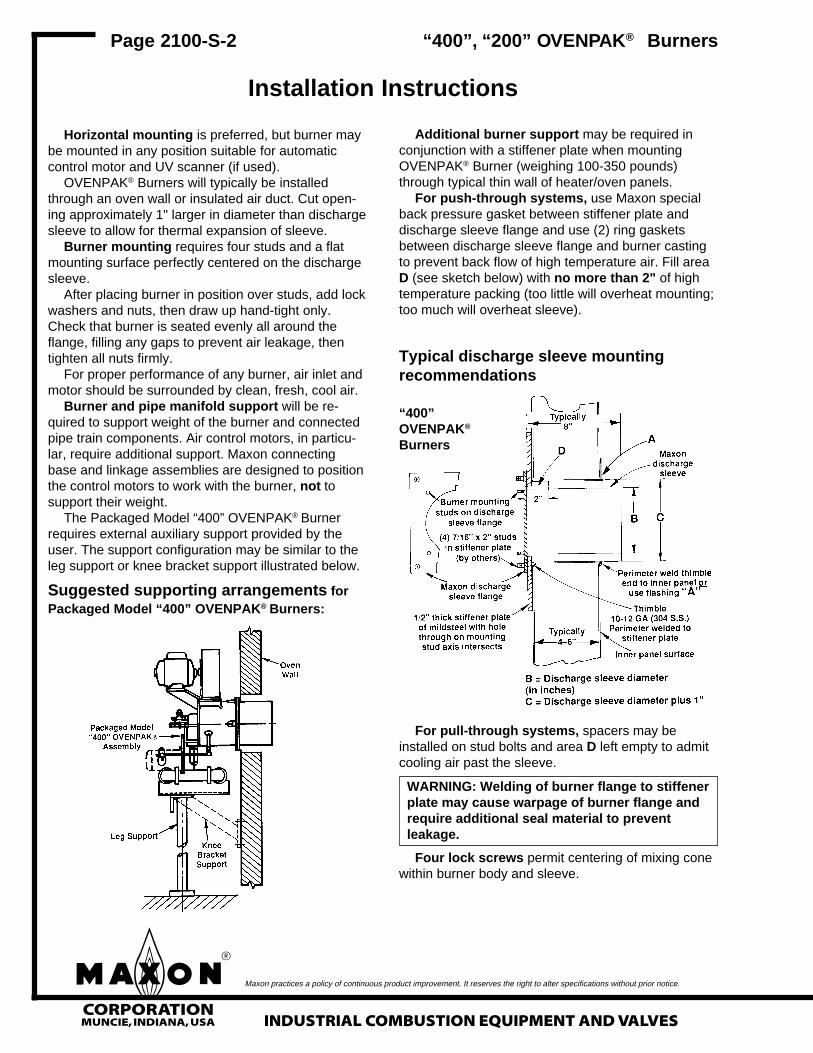
Suggested supporting arrangements forPackaged Model “400” OVENPAK® Burners:
Additional burner support may be required inconjunction with a stiffener plate when mountingOVENPAK® Burner (weighing 100-350 pounds)through typical thin wall of heater/oven panels.
For push-through systems, use Maxon specialback pressure gasket between stiffener plate anddischarge sleeve flange and use (2) ring gasketsbetween discharge sleeve flange and burner castingto prevent back flow of high temperature air. Fill areaD (see sketch below) with no more than 2" of hightemperature packing (too little will overheat mounting;too much will overheat sleeve).
“400”, “200” OVENPAK® Burners
For pull-through systems, spacers may beinstalled on stud bolts and area D left empty to admitcooling air past the sleeve.
WARNING: Welding of burner flange to stiffenerplate may cause warpage of burner flange andrequire additional seal material to preventleakage.
Four lock screws permit centering of mixing conewithin burner body and sleeve.
Typical discharge sleeve mountingrecommendations
“400”OVENPAK®
Burners

mCORPORATIONMUNCIE, INDIANA, USAINDUSTRIAL COMBUSTION EQUIPMENT AND VALVES
Maxon practices a policy of continuous product improvement. It reserves the right to alter specifications without prior notice.
Page 2100-S-3
Installation Instructions
For “400” OVENPAK® Burners: Lock screwsshould be drawn up hand-tight, then backed out one-half turn to allow for cone expansion. They must bere-checked after start-up, and loosened if necessaryto prevent deformation of cone. See start-up instruc-tions for details. Over-tightening lock screws canlead to cone distortion and greatly reduce coneand discharge sleeve life.
Discharge sleeve must be flush with, or extendbeyond, interior wall. Maxon can supply a special 12"long discharge sleeve, but higher noise levels mayresult, particularly when firing on propane.
An external viewing port should be provided forflame observation, preferably in such a position thatburner pilot and main flame can both be seen.
Flame sensing can be accomplished by eitherflame rod or UV scanner. When UV scanner is used,it should be kept as close to burner as feasible. Heatblock, if used, may affect signal strength with somebrands of scanners.
For “400” OVENPAK® Burners, field conversionfrom a flame rod version to a UV scanner version andvice versa may require additional parts in the burner.Contact Maxon for requirements.
Alternate fuels may require correction of supplypressures.
If OVENPAK® Burner is equipped with Maxon Hi/LoControl Motor, low-fire start wiring can be accom-plished as shown in the sketch below.
Maxon assumes no responsibility for the use ormisuse of the layouts shown. Specific pipingand wiring diagrams should always be submit-ted to the appropriate agencies for approval oneach application.
Multi-burner installations require special consid-erations if supplied by a common pipe train and/or airsupply. Air and Gas Balancing Valves should beused for improved heating uniformity; Gas Swing-Check Valves should be installed as close as pos-sible to each burner inlet for dependable lightoff (gasmanifold may otherwise act as a reservoir, preventinglightoff during trial-for-ignition period).
Control system’s circuitry must not allow mainFuel Shut-Off Valve to be opened unless combustionair is on, and must de-energize valve upon loss ofcombustion air pressure, along with the other usualsystem interlocks. Motor starter is to be interlockedwith valve, whether or not a combustion air pressureswitch is used.
4/98
“400”, “200” OVENPAK® Burners
mCORPORATIONMUNCIE, INDIANA, USA INDUSTRIAL COMBUSTION EQUIPMENT AND VALVES
Maxon practices a policy of continuous product improvement. It reserves the right to alter specifications without prior notice.
Read complete instructions before proceeding,and familiarize yourself with all the system's equip-ment components. Verify that your equipment hasbeen installed in accordance with the original manu-facturer's current instructions.
CAUTION: Initial adjustment and light-offshould be undertaken only by trained andexperienced personnel familiar with combus-tion systems, with control/safety circuitry, andwith knowledge of the overall installation.Instructions provided by the company and/orindividuals responsible for the manufactureand/or overall installation of complete systemincorporating Maxon burners take precedenceover these provided by Maxon. If Maxoninstructions conflict with any codes or regula-tions, contact Maxon Corporation beforeattempting start-up.
For initial OVENPAK® Burner start-up:
1. Close all burner fuel valves and cocks. Makepreliminary adjustments to fuel gas regulators.Remove pilot and main gas regulator’s adjustingscrew covers. Turn adjusting screw down (clock-wise) to approximately mid-position. Close pilotgas adjustable orifice screw by turning in clock-wise until it stops. (Do not over-tighten.) Thenback out the adjustable orifice (counter-clockwise)approximately 2-3 turns.
2. Check all electric circuitry. Verify that all controldevices and interlocks are operable and function-ing within their respective settings/ranges. Besure all air and gas manifolds are tight and thattest ports are plugged if not being used.
3. Check that all duct and chamber dampers areproperly positioned and locked into operatingpositions.
4. Disconnect the automatic control motor’slinkage from the “400” OVENPAK® Burner’soperating crank arm by loosening the controlmotor’s connecting rod from the burner’s togglelinkage.
For Model EB-MRV and Model “200”OVENPAK® Burners, the connecting linkage onthe separate control valve must be similarlyloosened and disconnected. Refer to specificadjusting procedures relating to control valveadjustment in Maxon catalog.
Initial start-up adjustment should only beaccomplished during a manual burner controlmode.
5. Start all system-related fans and blowers.Check for proper motor rotation and impellerdirection. Verify that all control interlocks areworking. Allow air handling equipment to run foradequate purge of your manifolds and combus-tion chamber plenums. With main gas shut off,manually advance burner to high fire position sothat air only flows through burner and combustionchamber.
CAUTION: Do not by-pass control panel timerstypically controlling sequential operations.
For EB OVENPAK® Burners only (step 6)
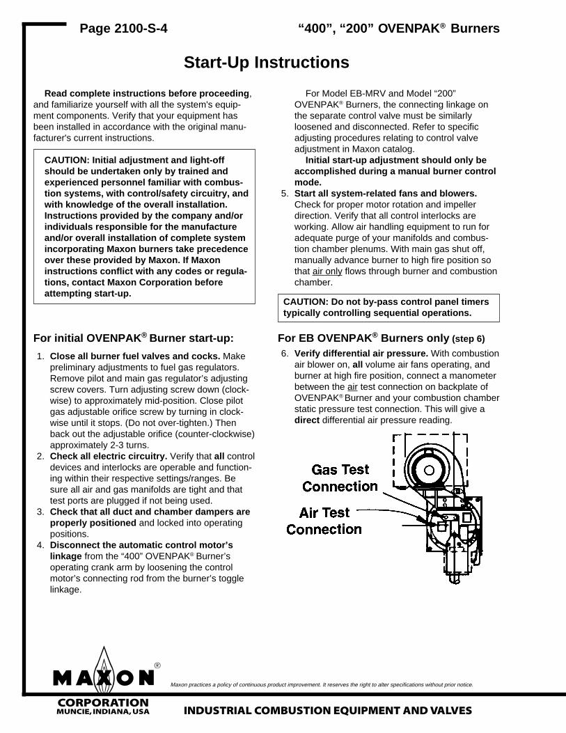
6. Verify differential air pressure. With combustionair blower on, all volume air fans operating, andburner at high fire position, connect a manometerbetween the air test connection on backplate ofOVENPAK® Burner and your combustion chamberstatic pressure test connection. This will give adirect differential air pressure reading.
Page 2100-S-4
Start-Up Instructions
“400”, “200” OVENPAK® Burners
mCORPORATIONMUNCIE, INDIANA, USAINDUSTRIAL COMBUSTION EQUIPMENT AND VALVES
Maxon practices a policy of continuous product improvement. It reserves the right to alter specifications without prior notice.
Determine your differential air pressure readingby taking an additional reading with manometerconnected between the burner’s air pressure testport and atmosphere with the burner at high fireposition, fuel valves closed, and all air handlingsystems running. Subtract the combustionchamber static pressure obtained above from thisair pressure reading to give you differential airpressure reading.
For Model “200” OVENPAK® Burner only(steps 6A-6C)
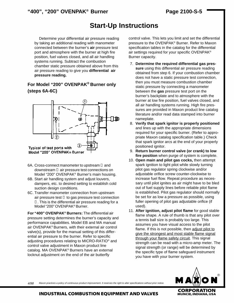
6A. Cross-connect manometer to upstream ① anddownstream ② air pressure test connections onModel “200” OVENPAK® Burner’s main housing.
6B. Start air handling system and adjust louvers,dampers, etc. to desired setting to establish coldsuction design conditions.
6C. Transfer manometer connection from upstreamair pressure test ① to gas pressure test connection③ . This is the differential air pressure reading for aModel “200” OVENPAK® Burner.
For “400” OVENPAK® Burners: The differential airpressure setting determines the burner’s capacity andperformance capabilities. Model EB and MA manualair OVENPAK® Burners, with their external air controlvalve(s), provide for the manual setting of this differ-ential air pressure to the burner. Refer to specificadjusting procedures relating to MICRO-RATIO® andcontrol valve adjustment in Maxon product linecatalog. MA OVENPAK® Burners have an externallocknut adjustment on the end of the air butterfly
control valve. This lets you limit and set the differentialpressure to the OVENPAK® Burner. Refer to Maxonspecification tables in the catalog for the differentialair settings required for your specific OVENPAK®
Burner capacity.
7. Determine the required differential gas pres-sure using this differential air pressure readingobtained from step 6. If your combustion chamberdoes not have a static pressure test connection,then you must measure combustion chamberstatic pressure by connecting a manometerbetween the gas pressure test port on theburner’s backplate and to atmosphere with theburner at low fire position, fuel valves closed, andall air handling systems running. High fire pres-sures are provided in Maxon product line catalogliterature and/or read data stamped into burnernameplate.
8. Verify that spark ignitor is properly positionedand lines up with the appropriate dimensionsrequired for your specific burner. (Refer to appro-priate Maxon catalog specification table.) Checkthat spark ignitor arcs at the end of your properlypositioned ignitor.
9. Return burner control valve (or crank) to lowfire position when purge of system is complete.
10. Open main and pilot gas cocks, then attemptspark ignition to light pilot while slowly turningpilot gas regulator spring clockwise and/oradjustable orifice screw counter-clockwise toincrease fuel flow. Repeat procedure as neces-sary until pilot ignites as air might have to be bledout of fuel supply lines before reliable pilot flameis established. Pilot gas regulator should normallybe set for as low a pressure as possible, usingfuller opening of pilot gas adjustable orifice (ifused).
11. After ignition, adjust pilot flame for good stableflame shape. A rule of thumb is that any pilot overa tennis ball size is probably too large. Thisassumes you have visual access to the pilotflame. If this is not possible, then adjust pilot togive the strongest and most stable flame signalthrough your flame safety circuit. This signalstrength can be read with a micro-amp meter. Thesignal strength (or range) will be determined bythe specific type of flame safeguard instrumentyou have with your burner system.
Page 2100-S-5
Start-Up Instructions
“400”, “200” OVENPAK® Burner
4/98
mCORPORATIONMUNCIE, INDIANA, USA INDUSTRIAL COMBUSTION EQUIPMENT AND VALVES
Maxon practices a policy of continuous product improvement. It reserves the right to alter specifications without prior notice.
Cycle burner from minimum to maximumand refine adjustment, if necessary.
For operation with interrupted pilot (asrecommended), shut off pilots and cycle burnerfrom minimum to maximum and back severaltimes to verify the flame is maintained.
15. When burner performance is satisfactory andstable throughout the firing range, reconnectcontrol motor.
For “400” OVENPAK® Burners: Reconnectlinkage to control motor. Control linkage travelmust be such that burner crank is moved through-out its complete travel, or cataloged capacitiesand turndowns will not be achieved. If less thanfull-rated burner capacity is required, linkage canbe adjusted to limit maximum output.
With interrupted pilot, it may be necessary toset control for somewhat higher than minimumburner setting to permit hold-in of flame detectionsystem without pilot.
CAUTION: Internal drive mechanism within thecontrol motor may be damaged if linkage isadjusted so as to cause binding with burner inhigh or low fire position.
16. Re-check differential gas pressure with unit atoperating temperature. Refine high fire setting ifnecessary, considering differential pressure,flame length, and appearance. Natural gas flameshould normally be predominantly clear blue butpossibly with semi-luminous tips. Dust or contami-nants in the air stream may affect flame appear-ance.
17. For “400” OVENPAK® Burners: Check forcontact between mixing cone and top-mostcentering screw after system has reachedmaximum operating temperature. If set screwtouches cone, back off an additional 1/8 turn ontop and both side set screws.
18. Plug all test connections not in use to avoiddangerous fuel leakage. Replace equipmentcover caps and tighten linkage screws.
12. Re-check pilot ignition by closing pilot gas cockor otherwise causing pilot outage. Re-light andrefine pilot gas adjustment as necessary to getignition within a second or two. The flame safe-guard relays should now power your main fuelShut-Off Valve(s).
CAUTION: After completing steps above, re-check all interlocking safety components andcircuitry to prove that they are properly in-stalled, correctly set, and fully operational. If indoubt, shut the system down, close pilot cockand contact responsible individual beforeproceeding further.
13. Establish main flame. With burner at low fireposition, back out main gas pressure regulatoradjusting screw (counter-clockwise) to get lowestoutlet pressure possible. Open all manual fuelshut-off valves (automatic fuel shut-off valveshould already be open) so gas flows to burnerinlet. There should be little, if any, change inflame appearance. Turn main regulator adjust-ing screw in (clockwise) to obtain outlet pressureof about 4"-6" wc higher than combustion cham-ber pressure (2"-4" wc for propane, considerablyhigher for some EB versions). Main flame shouldnow appear larger than pilot-only flame.
14. Establish high fire setting by slowly movingburner toward high fire position while observinggas pressure at burner gas test connection.Refine main gas regulator adjustment as neces-sary to provide correct differential pressure(gauge to combustion chamber, see step 7) athigh fire. If pressure cannot be adjusted lowenough, a different regulator or regulator springmay be necessary, or a limiting orifice valve (suchas Maxon's Series “BV”) should be added. Donot, however, exceed 4" wc pressure dropbetween regulator outlet and burner inlet.
CAUTION: If burner(s) go out, close shut-offvalve or shut main gas cock at once. Return tominimum setting, re-light pilots if necessary,then turn main gas on again. Check carefullythat every burner is lit before proceeding.
Page 2100-S-6
Start-Up Instructions
“400”, “200” OVENPAK® Burners

mCORPORATIONMUNCIE, INDIANA, USAINDUSTRIAL COMBUSTION EQUIPMENT AND VALVES
Maxon practices a policy of continuous product improvement. It reserves the right to alter specifications without prior notice.
19. Check out overall system operation by cyclingthrough light-off at minimum, interrupting pilot,and allowing temperature control system to cycleburner from minimum to maximum and return.Recheck all safety system interlocks for propersetting and operation.
NOTE: Typical gas firing control sequence for Maxonburner is provided only as a guide. Instructionsprovided by complete system manufacturer incorpo-rating Maxon burners take precedence.
For gas firing Model “400” OVENPAK® Burner
Light-off: Shut-down:1. Close cocks, shut-off valve(s) 1. Close main &2. Verify burner at low fire pilot gas cocks3. Start recirculating/exhaust fans 2. Keep combustion4. Start burner blower air blower running5. Purge at least 4 air changes after shut-down long6. Open pilot & main gas cocks enough to allow
burner to cool
WARNING: Test every UV installation fordangerous spark excitation from ignitors andother possible sources of direct or reflected UVradiation. Use only gas-tight scannerconnections.
20. Before system is placed into full service,instruct operator personnel on proper start-upoperation with shut-down of system, establishingwritten instructions for their future reference.
Page 2100-S-7“400”, “200” OVENPAK® Burners
Start-Up Instructions
4/98

mCORPORATIONMUNCIE, INDIANA, USA INDUSTRIAL COMBUSTION EQUIPMENT AND VALVES
Maxon practices a policy of continuous product improvement. It reserves the right to alter specifications without prior notice.
Page 2100-S-8
Notes“400”, “200” OVENPAK® Burners


![400 Ovenpak AP - Maxon Corporation€¦ · 1-1.2-ap-® [1]](https://static.fdocuments.net/doc/165x107/5ec3c39a762e251bd71bad56/400-ovenpak-ap-maxon-corporation-1-12-ap-1.jpg)


