MassDOT Separated Bike Lane Planning & Design Guide ... · 6D for recommended and optional...
18
Bicyclists have unique needs at signalized intersections. Bicycle movements may be controlled by the same indications that control motor vehicle movements, by pedestrian signals, or by bicycle- specific traffic signals. As discussed in Chapter 1 , bicyclists have unique operating characteristics that may be addressed with bike signals. In addition, as discussed in Chapter 4, the introduction of separated bike lanes creates situations that may require leading or protected phases for bicycle traffic, or place bicyclists outside the cone of vision of existing signal equipment. In these situations, provision of signals for bicycle traffic will be required. 6 SIGNALS
Transcript of MassDOT Separated Bike Lane Planning & Design Guide ... · 6D for recommended and optional...
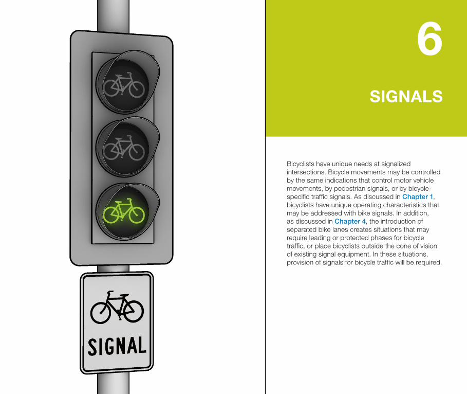
Bicyclists have unique needs at signalized intersections. Bicycle movements may be controlled by the same indications that control motor vehicle movements, by pedestrian signals, or by bicycle-specific traffic signals. As discussed in Chapter 1, bicyclists have unique operating characteristics that may be addressed with bike signals. In addition, as discussed in Chapter 4, the introduction of separated bike lanes creates situations that may require leading or protected phases for bicycle traffic, or place bicyclists outside the cone of vision of existing signal equipment. In these situations, provision of signals for bicycle traffic will be required.
6SIGNALS
106 MassDOT Separated Bike Lane Planning & Design Guide
6 S
IGN
ALS
6.1 GUIDANCE FOR SIGNALIZATION
The designer should review existing traffic volumes, traffic signal equipment, and phasing for any signalized intersection along a separated bike lane. Bike signal control may be achieved through minor modification of existing signal equipment or with installation of a new traffic signal.
Consideration should be given to:
• Existingsignalequipmentandvisibility
• Existingsignaltimingandphasing
• Conflictsbetweenturningvehiclesandbicycles
• Sightlinesbetweenturningvehiclesandbicycles
• Signaltimingandclearancesforbicycles
• Signaldetectionforbicycles
This chapter discusses the need for bike signals, as well as design controls for signal phasing and equipment.
6.1.1 TRAFFIC SIGNAL WARRANT
In general, the addition of a separated bike lane at an intersection will not require installation of a new traffic control signal at existing unsignalized intersections. The decision to use traffic signals should follow the signal warrants specified in the MUTCD.
When evaluating warrants for a potential signal, the designer should be aware that separated bike lanes attract additional users which could result in an intersection meeting warrants for a signal within a short time of the facility opening. Therefore anticipated future volumes of bicyclists should be considered during any warrant analysis effort. The designer should also evaluate the pedestrian hybrid beacon warrant, counting bicyclists as pedestrians, for crossings of high volume (more than 250 vehicles/hour) or high speed (greater than 30 mph) roadways.
6.1.2 BIKE SIGNAL HEAD WARRANT
Bike signals should generally be installed at all traffic control signals where separated bike lanes are present to provide a uniform indication for bicyclists. Requiring bicyclists to follow a mixture of pedestrian signal, vehicle signal and bike signal indications may result in confusion and lower signal compliance. While the use of bike signal heads is not required, under the following circumstances bike signal heads shall be provided to ensure safety for bicyclists:
• Locationswhereleadingorprotectedphasesareprovidedforbicyclists
• Locationswithcontra-flowbicyclemovements
• Locationswhereexistingtrafficsignalheadsarenotvisibletoapproachingbicyclists
• Locationswherebicyclistsarephysicallyseparatedfrommotoristsandpedestrians
6.1.3 CONSIDERATIONS FOR PROVIDING A PROTECTED BICYCLE PHASE
Separate bicycle phases are not required at signal controlled intersections. The decision to provide a protected bicycle phase should be based on a need to eliminate conflicts. The provision of protected movements may require the presence of motor vehicle turn lanes on the intersection approach. Scenarios where provision of a separate phase should be considered are discussed on the following page. These include:
• Locationswithtwo-wayorcontra-flowbicyclemovements
• Locationswithuniqueorhighvolumebicyclemovements
• Locationswithhighvolumesofturningtraffic

107MassDOT Separated Bike Lane Planning & Design Guide
6 S
IGN
ALS
LOCATIONS WITH HIGH VOLUMES OF TURNING TRAFFIC
Time-separated turning movements should be considered in locations with the motor vehicle turn volumes in EXHIBIT6A.
In locations where the roadway width does not allow for the provision of turn lanes and therefore limits phasing options, the designer should consider access management measures to reduce conflicts (see Section4.3.7). Where conflicts with permissive turns are necessary, enhanced treatments should be considered to reduce speeds and increase sight distance (see Section4.3.1).
Separated Bike Lane Operation
Motor Vehicles per Hour Turning across Separated Bike Lane
Two-way Street One-way Street
Right TurnLeft Turn
across One Lane
Left Turn across Two
Lanes
Right or Left Turn
One-way 150 100 50 150
Two-way 100 50 0 100
LOCATIONS WITH TWO-WAY OR CONTRA-FLOW BICYCLE MOVEMENTS
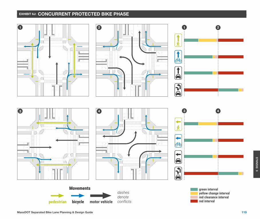
As discussed in Chapter4, bicyclists may be exposed to increased conflicts with left turning motorists on two-way streets with two-way separated bike lanes on one or both sides. The conflicts result when the bicyclists traveling in the same direction as the left turning motorist is not seen. While the motorist is scanning for a gap in traffic, they may not detect a bicyclist arriving from behind them and entering the crossing. Depending upon the time of arrival and the size of the intersection, there may be little time for either party to react. Where geometric solutions such as raised crossings or recessed crossings are not feasible or do not mitigate the conflict, the provision of a protected left turn phase or a protected bike phase should be considered to separate this conflict in time. Examples of potential phasing are shown in EXHIBIT6J,EXHIBIT6K,andEXHIBIT6L.
LOCATIONS WITH UNIQUE OR HIGH VOLUME BICYCLE MOVEMENTS
At locations where bicycle volumes and/or parallel pedestrian volumes are high, turning vehicles may find it difficult to find a safe gap to turn across. Separating the turning vehicle movements from the through bicycle and pedestrian movements may reduce delays and frustrations for all users.
6.1.4 CONSIDERATIONS FOR PROVIDING A LEADING BICYCLE INTERVAL
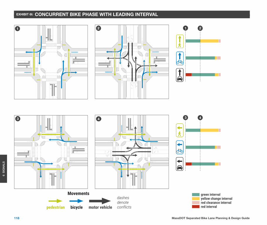
At locations where bicycle volumes and/or motorist turning volumes are lower than the threshold to provide a protected phase, or at locations where provision of a protected phase is not feasible, there may be benefits to providing a leading bicycle phase. A leading bicycle interval allows a bicyclist to enter the street crossing prior to a turning motorist, thereby improving their visibility. In some cases, a leading bicycle interval may allow bicyclists to clear the conflict point before motor vehicles enter. A parallel leading pedestrian interval should also be provided. An example of potential phasing is shown in EXHIBIT6I.
EXHIBIT 6A: Considerations for Time-separated Bicycle Movements

108 MassDOT Separated Bike Lane Planning & Design Guide
6 S
IGN
ALS
6.2 SIGNAL DESIGN
6.2.1 TYPES OF BIKE SIGNALS
Bike signals take on two typical forms, as illustrated in EXHIBIT 6B. The first is a standard three section head with circular signal faces. A BICYCLE SIGNAL sign (R10-10b) mounted below the signal head designates the signal for the exclusive use of bicyclist movements. It is permitted for general use under the MUTCD.
The second form of bike signal provides a three section head with bicycle symbols on each face. The use of bike signal faces has been approved by FHWA (see Interim Approval IA-16 for further details). The application and use of bike signal faces should be designed in accordance with the latest version of the MUTCD and associated interim approvals. If bicycles signals are to be used, the controlling municipality should amend the local traffic code to define their meaning.
6.2.2 BIKE SIGNAL EQUIPMENT
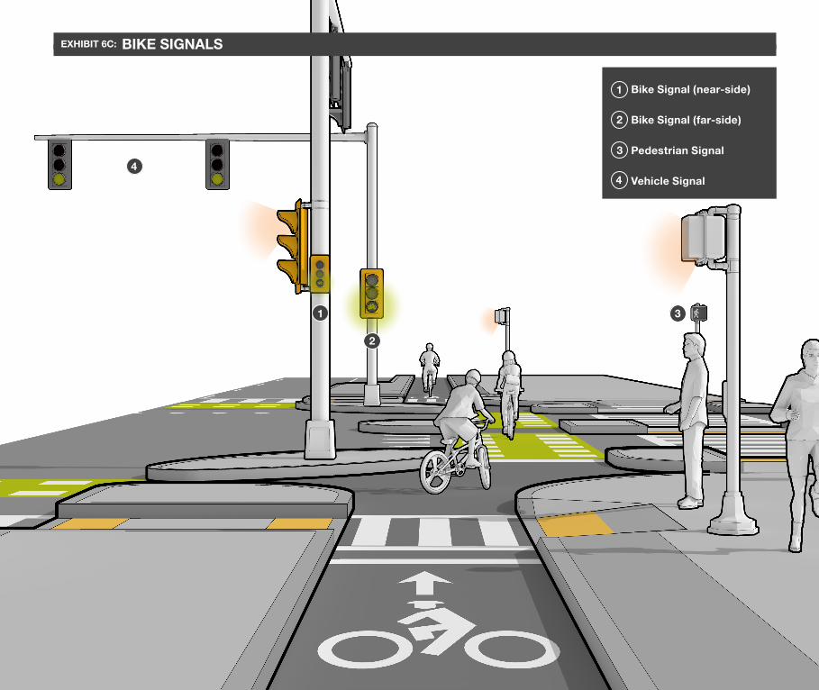
The layout of traffic signals is an important task for ensuring the safe operation of a separated bike lane (see EXHIBIT 6C). The MUTCD establishes requirements for where traffic signal displays can be placed in an intersection. The following guidance supplements the MUTCD.
Bike Signal FacesStandard Signal Faces
R10-10b (required)
R10-10b (optional)
SIZE OF DISPLAYS
Standard traffic signals are 12 in. in diameter. The MUTCD permits the use of an 8 in. circular indication for the sole purpose of controlling a bikeway or a bicycle movement (see MUTCD Section 4D.07). The interim approval also authorizes the use of 4 in. bicycle faces as a supplemental near-side signal.
NUMBER OF DISPLAYS
The MUTCD prescribes the use of two signal faces for the primary movement. In the case of a separated bike lane, one signal face is sufficient, however supplemental near-side signal may be used for clarifying traffic control at the intersection for bicyclists.
EXHIBIT 6B: Typical Forms of Bike Signals
109MassDOT Separated Bike Lane Planning & Design Guide
6 S
IGN
ALS
1 Bike Signal (near-side)
2 Bike Signal (far-side)
3 Pedestrian Signal
4 Vehicle Signal
1
2
3
4
EXHIBIT 6C: BIKE SIGNALS
110 MassDOT Separated Bike Lane Planning & Design Guide
6 S
IGN
ALS
VISIBILITY OF SIGNAL FACES
The designer should take care to ensure traffic signals and bike signal heads are visible for approaching bicyclists. Where existing traffic signals are anticipated to be the sole source of guidance for bicyclists, they should be located within the cone of vision measured from the bike stop bar (see MUTCD Section 4D.13 for further detail). This is especially important to consider in locations with contra-flow or two-way bike facilities. If the signals fall outside the cone of vision, supplementary bike signal heads shall be provided.
Section 4D.12 of the MUTCD states that signals should be designed to “optimize the visibility of signal indications to approaching traffic” and that road users shall be given a clear unmistakable indication of their right-of-way assignment. For separated bike lanes, this may mean that the bicycle traffic signal face should be optically programmed or shielded with louvers to prevent confusion for parallel motor vehicle traffic.
Designers should also ensure optically programmed or shielded signals are visible to approaching bicyclists where bicyclists are required to follow traffic signals or pedestrian signals.
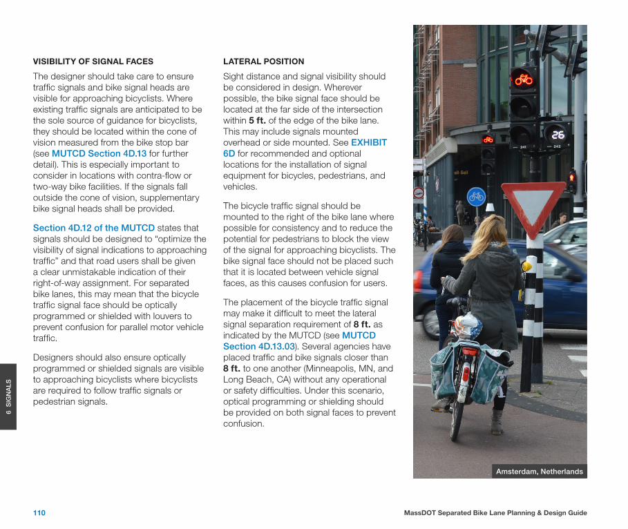
LATERAL POSITION
Sight distance and signal visibility should be considered in design. Wherever possible, the bike signal face should be located at the far side of the intersection within 5 ft. of the edge of the bike lane. This may include signals mounted overhead or side mounted. See EXHIBIT 6D for recommended and optional locations for the installation of signal equipment for bicycles, pedestrians, and vehicles.
The bicycle traffic signal should be mounted to the right of the bike lane where possible for consistency and to reduce the potential for pedestrians to block the view of the signal for approaching bicyclists. The bike signal face should not be placed such that it is located between vehicle signal faces, as this causes confusion for users.
The placement of the bicycle traffic signal may make it difficult to meet the lateral signal separation requirement of 8 ft. as indicated by the MUTCD (see MUTCD Section 4D.13.03). Several agencies have placed traffic and bike signals closer than 8 ft. to one another (Minneapolis, MN, and Long Beach, CA) without any operational or safety difficulties. Under this scenario, optical programming or shielding should be provided on both signal faces to prevent confusion.
Amsterdam, Netherlands
111MassDOT Separated Bike Lane Planning & Design Guide
6 S
IGN
ALS
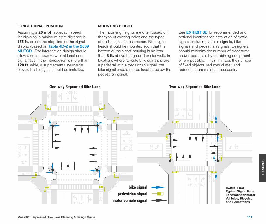
LONGITUDINAL POSITION
Assuming a 20 mph approach speed for bicycles, a minimum sight distance is 175 ft. before the stop line for the signal display (based on Table 4D-2 in the 2009 MUTCD). The intersection design should allow a continuous view of at least one signal face. If the intersection is more than 120 ft. wide, a supplemental near-side bicycle traffic signal should be installed.
MOUNTING HEIGHT
The mounting heights are often based on the type of existing poles and the types of traffic signal faces chosen. Bike signal heads should be mounted such that the bottom of the signal housing is no less than 8 ft. above the ground or sidewalk. In locations where far-side bike signals share a pedestal with a pedestrian signal, the bike signal should not be located below the pedestrian signal.
See EXHIBIT 6D for recommended and optional locations for installation of traffic signals including vehicle signals, bike signals and pedestrian signals. Designers should minimize the number of mast arms and/or pedestals by combining equipment where possible. This minimizes the number of fixed objects, reduces clutter, and reduces future maintenance costs.
One-way Separated Bike Lane Two-way Separated Bike Lane
bike signalpedestrian signal
motor vehicle signal
EXHIBIT 6D: Typical Signal Face Locations for Motor Vehicles, Bicycles and Pedestrians

112 MassDOT Separated Bike Lane Planning & Design Guide
6 S
IGN
ALS
6.2.3 PEDESTRIAN SIGNAL EQUIPMENT
The designer should carefully consider the placement of pedestrian signal equipment with relation to the separated bike lane. Under all scenarios, designers must ensure that all proposed pedestrian ramps, push buttons, and signals meet current accessibility guidance, including the minimum separation of 10 ft. between accessible pedestrian push buttons (see EXHIBIT 6E).
Pedestrian signal timing should include sufficient clearance time for a pedestrian to cross the entire roadway including the bike lanes and street buffers. Pedestrian signal equipment should be located within the sidewalk buffer adjacent to the curb ramp outside of the bike lane. Designers should ensure that pedestrian signals meet all current accessibility guidelines with regards to proximity to the level landing area and reach range for the push button.
6.3 SIGNAL OPERATIONS
6.3.1 SIGNAL PHASING
Traffic signal phasing represents the fundamental method by which a traffic signal accommodates the various users at an intersection in a safe and efficient manner. Under the control of a bicycle-specific traffic signal, bicyclists’ movement may occur concurrently with other compatible vehicle phases or exclusively on a separate phase.
The signal phasing for bikes may provide concurrent phasing with through vehicle traffic, a leading bicycle interval, a protected bicycle phase, or turning bike phases.
As described in Section 6.1, the designer will have to evaluate the need to provide a protected bicycle phase where left and right turn motor vehicle volumes across the bike lane are high. Designers should consider providing protected-only left turn phasing wherever feasible for signalized approaches where left turning motor vehicle movements cross a separated bike lane.
Protected right turn phases are desirable in locations where high volumes of right turning vehicles conflict with a parallel separated bike lane. However, provision of a protected right turn phase carries several challenges, including the need for a right turn lane and impacts to level of service and queueing. In locations where parking lanes are provided, elimination of
Designers should minimize the number of mast arms and/or pedestals by combining equipment where possible. This minimizes the number of fixed objects, reduces clutter and minimizes future maintenance costs.
10’ min.
EXHIBIT 6E: Minimum Separation between Accessible Pedestrian Push Buttons
the parking on the intersection approach can allow for the provision of a right turn lane to accommodate a protected phase. If it is not possible to provide protected turn signal phasing, designers should consider implementing flashing yellow arrow signal phasing for permissive right or left turn movements that conflict with a concurrent bike movement. Further guidance for the installation and operation of flashing yellow arrow indications for permissive left and right turn movements may be found in section 4D.18 and 4D.22 of the MUTCD, respectively.
113MassDOT Separated Bike Lane Planning & Design Guide
6 S
IGN
ALS
EXHIBIT 6H through EXHIBIT 6L (at the end of this chapter) show five scenarios for bike signal phasing, ranging from fully concurrent to protected phasing that should be considered at intersections with separated bike lanes.
6.3.2 SIGNAL TIMING
The updated Traffic Signal Timing Manual (FHWA, 2nd Edition, 2015) has guidance on intervals for accommodating and encouraging bicycle travel. In locations where bike signals are not provided, signal timing for standard traffic signals along a corridor with a separated bike lane must be designed to accommodate bicyclists. The designer must consider the differing operating characteristics of bicyclists which impact parameters such as minimum green time, extension time, and clearance intervals. In locations where bike signals are provided, the designer may provide separate signal timing for bicycles, reducing unnecessary delay for vehicles in the adjacent travel lanes.
MINIMUM GREEN TIME
Minimum green time is used to allow people to react to the start of the green interval and meet reasonable expectations for how long a signal will be green (see Traffic Signal Timing Manual). Traffic signal control for a separated bike lane must provide sufficient minimum green time for a bicyclist to clear the intersection from
a stopped position. The designer should consider the operating characteristics of a bicycle when calculating the required minimum green time. In locations where bike signals are not provided, the designer should allow for a minimum bicycle green time as a part of the timing for the concurrent vehicle signal phase. In locations where bicycle detection is provided within the separated bike lane, the signal timing should be designed to allow for an actuated minimum bicycle green time, if possible.
EXTENSION TIME (PASSAGE GAP)
In locations where bike detection is provided for actuated signal phasing, extension time may be provided as appropriate to extend the bicycle green phase up to the maximum green time. Bicycle detectors used for extension purposes should be located at the stop bar.
CHANGE AND CLEARANCE INTERVALS
The intent of the vehicle phase change and clearance intervals is to provide a safe transition of right-of-way. Traffic signal control for bicyclists should provide adequate clearance time to allow a bicyclist who enters at the end of the green phase to safely cross the intersection prior to the beginning of the conflicting signal phase. Designers should ensure that the combined yellow and all-red intervals for
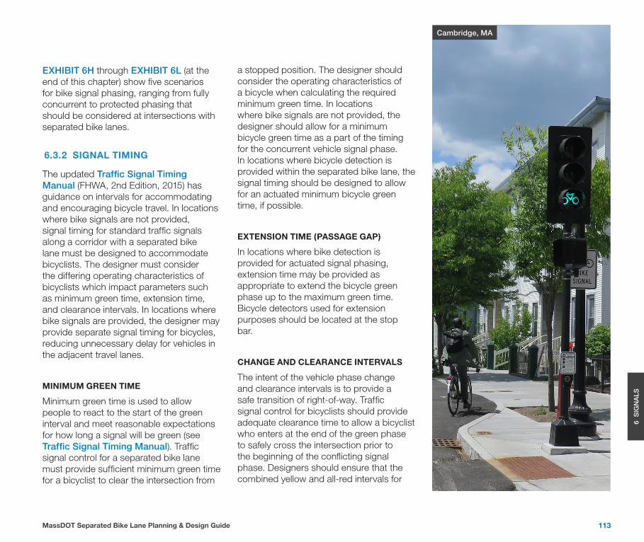
Cambridge, MA
114 MassDOT Separated Bike Lane Planning & Design Guide
6 S
IGN
ALS
concurrent bicycle and vehicle movements are equal. However, the individual yellow and all-red interval values may vary between modes based on engineering judgement. In calculating the clearance intervals, designers should include any grade differential through the intersection, which may significantly impact bicycle crossing time. In locations where bike signals are not provided, the bicycle crossing time may be accommodated during the combined yellow and all-red vehicle intervals.
• Two-stage turn queue box – At locations where a two-stage turn queue box is provided for turns from the separated bike lane, turns on red should be restricted from the side street, as turning motorists may otherwise obstruct the queue box.
• Two-way separated bike lanes – At locations where two-way separated bike lanes are provided, turns on red should be restricted from the side street adjacent to the facility, because motorists may not anticipate conflicts from bicyclists approaching in the contra-flow direction.
• Contra-flow separated bike lanes – At locations where contra-flow separated bike lanes are provided, turns on red should be restricted from the side street adjacent to the facility, because motorists may not anticipate conflicts from bicyclists approaching in the contra-flow direction.
• Protected bike phase – At locations where traffic signal phasing includes a protected bike phase, the designer should consider restricting turns on red for all movements which would conflict with the protected phase.
• Protected right turns – At locations where protected right turns are implemented to separate bicycle and pedestrian movements, turns on red should be restricted for the same movement.
• Leading bike phase – At locations where a leading bike phase is provided, designers should consider restricting turns on red for conflicting movements.
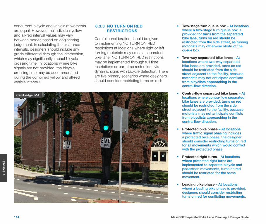
Cambridge, MA
6.3.3 NO TURN ON RED RESTRICTIONS
Careful consideration should be given to implementing NO TURN ON RED restrictions at locations where right or left turning motorists may cross a separated bike lane. NO TURN ON RED restrictions may be implemented through full time restrictions or part-time restrictions via dynamic signs with bicycle detection. There are five primary scenarios where designers should consider restricting turns on red:
115MassDOT Separated Bike Lane Planning & Design Guide
6 S
IGN
ALS
100’
bicycle detector
6.4 BICYCLE DETECTION
Bicycle detection is used at traffic signals to alert the signal controller to bicycle demand on a particular approach. Properly located detection enables the length of green time to fluctuate based on demand.
The addition of a separated bike lane may create a need to add a protected phase to separate turning motorists from through bicyclists. In those situations, it may be desirable to convert a pre-timed intersection into partially actuated intersection to maximize signal efficiency. In those locations, the addition of detection for bicyclists and relevant motorist turn lanes can minimize lost time. Regardless, the designer must consider the need for signal detection for any location where a separated bike lane will interact with a traffic signal.
The addition of detection and signal timing ensures that bicycles are provided safe crossing opportunities and reduces the potential for red-light running (provided that the signal timing is responsive to the bike lane). Detection also allows the intersection to operate more efficiently, especially during off-peak periods when traffic volumes are lower.
Bicycle detection may also be used to activate variable turn on red restriction signs to further increase safety.
Signal detection may be necessary or provide operational improvements under several scenarios:
• Actuated signals – Where the bicycle facility is located on any approach where the green phase may not be automatically called during every cycle, bicycle detection must be provided to ensure that bicyclists receive a green signal indication.
• Bicycle minimum green – In locations where vehicle minimum green times may be too short for a bicyclist to clear an intersection after starting from a stopped condition, the detection of a bicyclists should trigger an extension of the vehicle minimum green to provide the bicyclist minimum green time.
• Protected bicycle phases – In locations where protected bicycle phases are provided or where time-separated turn restrictions exist, bicycle detection should enable the signal to skip phases dynamically when bicyclists are not present.
The designer should ensure that detection significantly covers the entire approach. For locations where passive detection is used to capture both motorists and bicyclists, detection zones should be designed to capture approaching vehicles as well as bicycles within the separated bike lane. Where feasible, designers should provide passive detection, as it is more reliable in detecting bicycles and may be designed to limit the number of detectors required for parallel vehicle and bicycle approaches. Designers should ensure that, if used, loop detectors located within the vehicle travel lanes are still capable of functioning for bicyclists in order to accommodate those who approach from outside of the separated bike lane.
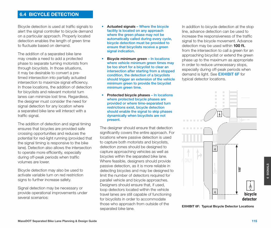
In addition to bicycle detection at the stop line, advance detection can be used to increase the responsiveness of the traffic signal to the bicycle movement. Advance detection may be used within 100 ft. from the intersection to call a green for an approaching bicyclist or extend the green phase up to the maximum as appropriate in order to reduce unnecessary stops, especially during off-peak periods when demand is light. See EXHIBIT 6F for typical detector locations.
EXHIBIT 6F: Typical Bicycle Detector Locations
116 MassDOT Separated Bike Lane Planning & Design Guide
6 S
IGN
ALS
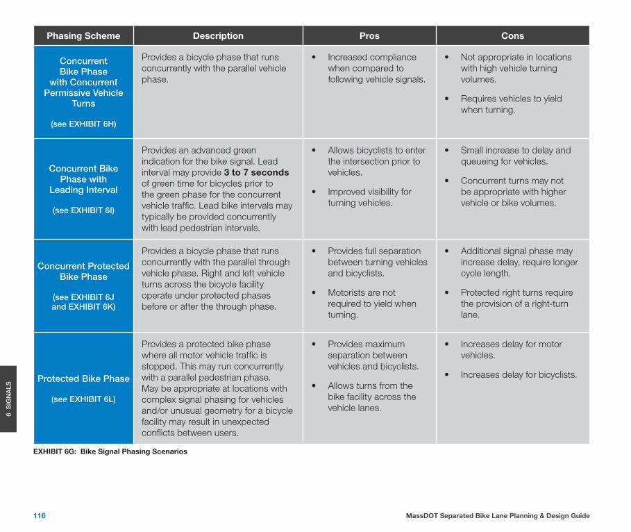
EXHIBIT 6G: Bike Signal Phasing Scenarios
Phasing Scheme Description Pros Cons
Concurrent Bike Phase
with Concurrent Permissive Vehicle
Turns
(see EXHIBIT 6H)
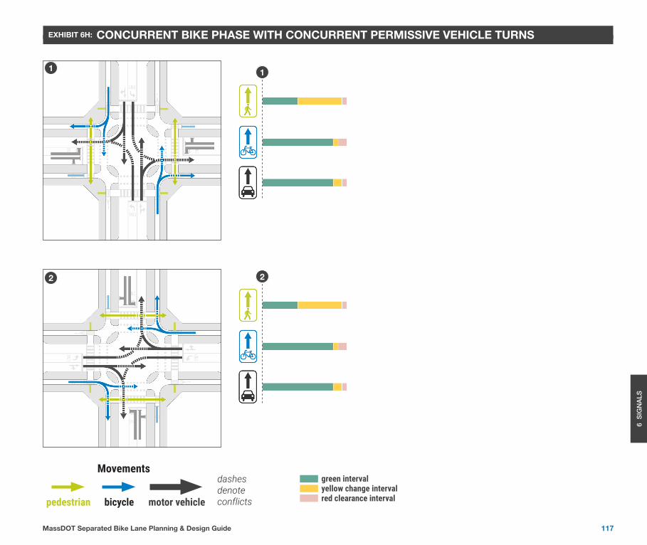
Provides a bicycle phase that runs concurrently with the parallel vehicle phase.
• Increased compliance when compared to following vehicle signals.
• Not appropriate in locations with high vehicle turning volumes.
• Requires vehicles to yield when turning.
Concurrent Bike Phase with
Leading Interval
(see EXHIBIT 6I)
Provides an advanced green indication for the bike signal. Lead interval may provide 3 to 7 seconds of green time for bicycles prior to the green phase for the concurrent vehicle traffic. Lead bike intervals may typically be provided concurrently with lead pedestrian intervals.
• Allows bicyclists to enter the intersection prior to vehicles.
• Improved visibility for turning vehicles.
• Small increase to delay and queueing for vehicles.
• Concurrent turns may not be appropriate with higher vehicle or bike volumes.
Concurrent Protected Bike Phase
(see EXHIBIT 6J and EXHIBIT 6K)
Provides a bicycle phase that runs concurrently with the parallel through vehicle phase. Right and left vehicle turns across the bicycle facility operate under protected phases before or after the through phase.
• Provides full separation between turning vehicles and bicyclists.
• Motorists are not required to yield when turning.
• Additional signal phase may increase delay, require longer cycle length.
• Protected right turns require the provision of a right-turn lane.
Protected Bike Phase
(see EXHIBIT 6L)
Provides a protected bike phase where all motor vehicle traffic is stopped. This may run concurrently with a parallel pedestrian phase. May be appropriate at locations with complex signal phasing for vehicles and/or unusual geometry for a bicycle facility may result in unexpected conflicts between users.
• Provides maximum separation between vehicles and bicyclists.
• Allows turns from the bike facility across the vehicle lanes.
• Increases delay for motor vehicles.
• Increases delay for bicyclists.
117MassDOT Separated Bike Lane Planning & Design Guide
6 S
IGN
ALS
EXHIBIT 6H: CONCURRENT BIKE PHASE WITH CONCURRENT PERMISSIVE VEHICLE TURNS
1 1
2 2
dashes denote conflicts
Movements
pedestrian bicycle motor vehicle
green intervalyellow change intervalred clearance interval
118 MassDOT Separated Bike Lane Planning & Design Guide
6 S
IGN
ALS
EXHIBIT 6I: CONCURRENT BIKE PHASE WITH LEADING INTERVAL
1
3
1
3
2
4
2
4
green intervalyellow change intervalred clearance intervalred interval
dashes denote conflicts
Movements
pedestrian bicycle motor vehicle
119MassDOT Separated Bike Lane Planning & Design Guide
6 S
IGN
ALS
EXHIBIT 6J: CONCURRENT PROTECTED BIKE PHASE
1
3
2
4
1
3
2
4
green intervalyellow change intervalred clearance intervalred interval
dashes denote conflicts
Movements
pedestrian bicycle motor vehicle
120 MassDOT Separated Bike Lane Planning & Design Guide
6 S
IGN
ALS
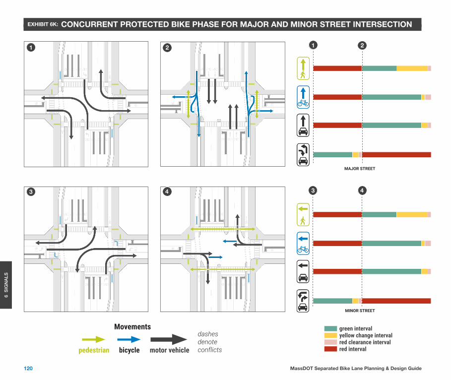
EXHIBIT 6K: CONCURRENT PROTECTED BIKE PHASE FOR MAJOR AND MINOR STREET INTERSECTION
MAJOR STREET
MINOR STREET
1 2 21
3 4 3 4
green intervalyellow change intervalred clearance intervalred interval
dashes denote conflicts
Movements
pedestrian bicycle motor vehicle
121MassDOT Separated Bike Lane Planning & Design Guide
6 S
IGN
ALS
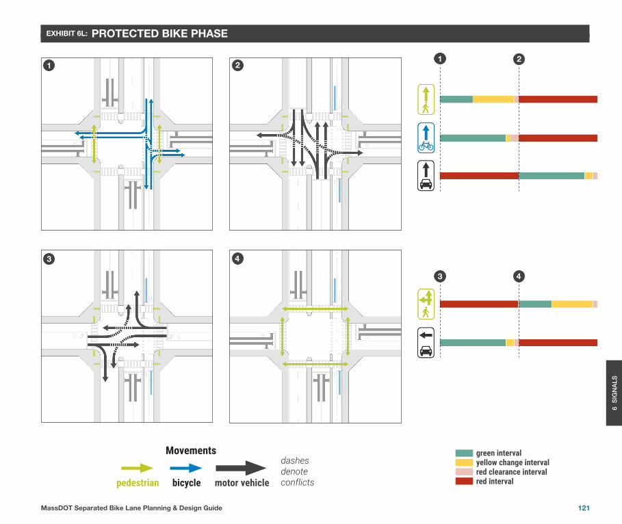
EXHIBIT 6L: PROTECTED BIKE PHASE
2121
43
43
green intervalyellow change intervalred clearance intervalred interval
dashes denote conflicts
Movements
pedestrian bicycle motor vehicle

This page left blank intentionally


![Welcome [] · for Tysons which will support multi-modal forms of transportation including transit, bicycles, pedestrians, and auto vehicles. Project Status and Schedule: • Preliminary](https://static.fdocuments.net/doc/165x107/5f09e7417e708231d4290e5a/welcome-for-tysons-which-will-support-multi-modal-forms-of-transportation-including.jpg)