Manufacturing optical fibresbythePCVD process - Philips Bound Archive... · Philips Tech. Rev. 44,...
9
Philips Tech. Rev. 44, No. 8/9/10, 241-249, May 1989 241 Manufacturing optical fibres by the PCVD process P. Geittner and H. Lydtin Copper wires or coaxial cablesfor communications are increasingly being replaced by optical fibres made of glass. The main reasons for this are the increased signal frequency and the lower attenuation. Ten years ago an attenuation of J dB/km might have seemed impressive; today an attenuation of 0.2 dB/km is attainable. The advantage of the very low attenuation is that fewer repeaters are required in transmission links, so that the costs per kilometre of trans- mission path diminish. Other advantages of optical fibres are their insensitivity to interference from electromagnetic fields and the ready availability of the basic raw material - silica. Op- tical fibres with very low attenuation can only be made from extremely pure materials, how- ever, and doping with special additives must be controlled very accurately. In the PCVD pro- cess (Plasma-activated Chemical Vapour Deposition), the result of research at Philips For- schungslaboratorium Aachen, these very difficult conditions can be met. Introduetion Optical methods for transrmttuig messages have been known for many thousands of years. In all such methods there is always a transmitter, a transmission path and a receiver. The transmitter can be thought of as the person sending smoke or light signals, the re- ceiver as the person who observes these signals and the transmission path as the atmosphere between the trans- mitter and the receiver. Two fairly advanced forms of Dr P. Geittner and Dr H. Lydtin are with Philips GmbH For- schungs/aboratorium Aachen, Aachen, West Germany. optical communication were Claude Chappe's visual (or semaphore) telegraph system [1], which was set up in France in the mid-19th century, and A. G. Bell's 'photophone' [2], see jig. 1. In spite of the enormous velocity of light the transmission rate was always lim- ited until fairly recently by the inertia of the transmit- [1] G. R. M. Garratt, The early history of telegraphy, Philips Tech. Rev. 26, 268-284, 1965. [2] C. Mackenzie, Alexander Graharn Bell, Grosset and Dunlap, New York 1928.
Transcript of Manufacturing optical fibresbythePCVD process - Philips Bound Archive... · Philips Tech. Rev. 44,...

Philips Tech. Rev. 44, No. 8/9/10, 241-249, May 1989 241
Manufacturing optical fibres by the PCVD process
P. Geittner and H. Lydtin
Copper wires or coaxial cablesfor communications are increasingly being replaced by opticalfibres made of glass. The main reasons for this are the increased signal frequency and thelower attenuation. Ten years ago an attenuation of J dB/km might have seemed impressive;today an attenuation of 0.2 dB/km is attainable. The advantage of the very low attenuation isthat fewer repeaters are required in transmission links, so that the costs per kilometre of trans-mission path diminish. Other advantages of optical fibres are their insensitivity to interferencefrom electromagnetic fields and the ready availability of the basic raw material - silica. Op-tical fibres with very low attenuation can only be made from extremely pure materials, how-ever, and doping with special additives must be controlled very accurately. In the PCVD pro-cess (Plasma-activated Chemical Vapour Deposition), the result of research at Philips For-schungslaboratorium Aachen, these very difficult conditions can be met.
Introduetion
Optical methods for transrmttuig messages havebeen known for many thousands of years. In all suchmethods there is always a transmitter, a transmissionpath and a receiver. The transmitter can be thought ofas the person sending smoke or light signals, the re-ceiver as the person who observes these signals and thetransmission path as the atmosphere between the trans-mitter and the receiver. Two fairly advanced forms of
Dr P. Geittner and Dr H. Lydtin are with Philips GmbH For-schungs/aboratorium Aachen, Aachen, West Germany.
optical communication were Claude Chappe's visual(or semaphore) telegraph system [1], which was set upin France in the mid-19th century, and A. G. Bell's'photophone' [2], see jig. 1. In spite of the enormousvelocity of light the transmission rate was always lim-ited until fairly recently by the inertia of the transmit-
[1] G. R. M. Garratt, The early history of telegraphy, PhilipsTech. Rev. 26, 268-284, 1965.
[2] C. Mackenzie, Alexander Graharn Bell, Grosset and Dunlap,New York 1928.
242 P. GEITTNER and H. LYDTIN Philips Tech. Rev. 44, No. 8/9/10
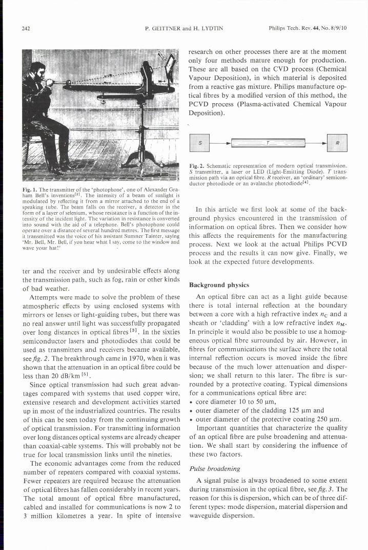
Fig.1. The transmitter of the 'photophone', one of Alexander Gra-ham Bell's inventions'U. The intensity of a beam of sunlight ismodulated by reflecting it from a mirror attached to the end of aspeaking tube. The beam falls on the receiver, a detector in theform of a layer of selenium, whose resistance is a function of the in-tensity of the incident light. The variation in resistance is convertedinto sound with the aid of a telephone. Bell's photophone couldoperate over a distance of several hundred metres. The first messageit transmitted was the voice of his assistant Sumner Tainter, saying'Mr. Bell, Mr. Bell, if you hear what I say, come to the window andwave your hat!'
ter and the receiver and by undesirable effects alongthe transmission path, such as fog, rain or other kindsof bad weather.Attempts were made to solve the problem of these
atmospheric effects by using enclosed systems withmirrors or lenses or light-guiding tubes, but there wasno real answer untillight was successfully propagatedover long distances in optical fibres [31. In the sixtiessemiconductor lasers and photodiodes that could beused as transmitters and receivers became available,seefig. 2. The breakthrough came in 1970, when it wasshown that the attenuation in an optical fibre could beless than 20 dB/km [51.
Since optical transmission had such great advan-tages compared with systems that used copper wire,extensive research and development activities startedup in most of the industrialized countries. The resultsof this can be seen today from the continuing growthof optical transmission. For transmitting informationover long distances optical systems are already cheaperthan coaxial-cable systems. This will probably not betrue for local transmission links until the nineties.
The economic advantages come from the reducednumber of repeaters compared with coaxial systems.Fewer repeaters are required because the attenuationof optical fibres has fallen considerably in recent years.The total amount of optical fibre manufactured,cabled and installed for communications is now 2 to3 million kilometres a year. In spite of intensive
research on other processes there are at the momentonly four methods mature enough for production.These are all based on the CVD process (ChemicalVapour Deposition), in which material is depositedfrom a reactive gas mixture. Philips manufacture op-tical fibres by a modified version of this method, thePCVD process (Plasma-activated Chemical VapourDeposition) .
Fig. 2. Schematic representation of modern optical transmission.S transmitter, a laser or LED (Light-Emitting Diode). T trans-mission path via an optical fibre. R receiver, an 'ordinary' semicon-ductor photodiode or an avalanche photodiodel+l.
In this article we first look at some of the back-ground physics encountered in the transmission ofinformation on optical fibres. Then we consider howthis affects the requirements for the manufacturingprocess. Next we look at the actual Philips PCVDprocess and the results it can now give. Finally, welook at the expected future developments.
Background physics
An optical fibre can act as a light guide becausethere is total internal reflection at the boundarybetween a core with a high refractive index ne and asheath or 'cladding' with a low refractive index nM'
In principle it would also be possible to use a homog-eneous optical fibre surrounded by air. However, infibres for communications the surface where the totalinternal reflection occurs is moved inside the fibrebecause of the much lower attenuation and disper-sion; we shall return to this later. The fibre is sur-rounded by a protective coating. Typical dimensionsfor a communications optical fibre are:• core diameter 10 to 50 urn,• outer diameter of the cladding 125 urn and• outer diameter of the protective coating 250 urn.Important quantities that characterize the quality
of an optical fibre are pulse broadening and attenua-tion. We shall start by considering the influence ofthese two factors.
Pulse broadening
A signal pulse is always broadened to some extentduring transmission in the optical fibre, seefig. 3. Thereason for this is dispersion, which can be of three dif-ferent types: mode dispersion, material dispersion andwaveguide dispersion.

Philips Tech. Rev. 44, No. 8/9/10 PCVD PROCESS 243
We shall first consider mode dispersion, for the sim-plest type of optical fibre, with a stepped refractive-index profile ('step-index fibre'), see fig. 4a. In a fibreof this type the refractive index in the core is constantand only slightly higher than that of the cladding. The
ilJ\M_t
stepped function of the radius. An optical fibre with arefractive-index profile of this form is called a 'graded-index fibre', see fig.4b. The smallest value for thetime-delay difference due to mode dispersion that cannow be obtained with these fibres is 50 ps/km. The
Fig. 3. Pulse broadening. Light pulses, shown here as the light intensity J as a function of time t,gradually become broader as the modulated light ray L propagates in an optical fibre with core Cand cladding M.
{J/ss;?st· -17 S ..--z~ -.Sé
@ @ 8]h_ _1
~
.
9 b f_r _r _r
Fig.4. a) Multimode fibre with stepped refractive-index profile.b) Graded-index multimode fibre with a continuous profile.c) Single-mode fibre. This fibre also has a stepped profile, but thecore diameter is so small that a light ray can only propagate in asingle mode. Top row: longitudinal sections. Centre row: cross-sections. Bottom row: refractive-index profiles, the difference /'o;n inrefractive index between core and cladding as a function of theradius r. Dark grey: cladding.
relative difference ~nrel in the refractive index, de-fined as:
is about 10,70. Inside the core the light from the lightpulse can propagate in various modes, which are de-termined by the fact that constructive interferencemust occur. The difference in optical pathlength andhence in time delay for the different modes causes thepulse broadening. For a step-index fibre the differencein delay time is about 50 ns/krn. This means that theproduct of the maximum signal frequency and thefibre length cannot be much more than 20 MHz km insuch fibres. This figure is no higher than for coaxialcables.
The mode dispersion can be reduced by making theoptical pathlength the same for the different modes.It is then necessary to make the refractive index varyas a continuous function n(r) = fer), rather than a
refractive-index profile required for this must satisfythe equation
where re is the maximum radius of the core. ~nrel re-fers to the largest relative difference in the refractiveindices and a is the 'profile parameter'. The profileparameter has a value of about 2; its exact value de-pends on the wavelength À of the light, ~nrel and theelements used as dopants in making the glass. Theproduct of the maximum signal frequency and thefibre length for these fibres is 10 to 20 GHz km in theideal case.The mode dispersion can be completely suppressed
by reducing the core diameter until only one mode canexist, see fig. 4c. These optical fibres are called single-mode fibres and their index-profile is stepped. If fibresof this type are designed for a wavelength of l300 nm,the core diameter is only 8 to 10 J.1mand the relativedifference in refractive-index ~nrel is 0.3 to 0.50Ja.Inthese fibres the maximum signal frequency is limitedonly by material dispersion and waveguide dispersion.
Material dispersion arises because the refractiveindex - and hence the velocity - is a function of thewavelength of the light in the material. This functiondepends on the composition of the glass. Since everylight source has a finite spectral width, some pulsebroadening due to material dispersion always occurs.Material dispersion is only of interest if mode disper-sion is small.
[3J K. C. Kao and G. A. Hockham, Dielectric-fibre surface wave-guides for optical frequencies, Proc. lEE 113, 1151-1158,1966.
[4J L. J. M. Bollen, J. J. Goedbloed and E. T. J. M. Smeets, Theavalanche photodiode, Philips Tech. Rev. 36, 205-210, 1976.
[5J F. P. Kapron, D. B. Keck and R. D. Maurer, Radiation lossesin glass optical waveguides, Appl. Phys. Lett. 17, 423-425,1970.
244 P. GEITTNER and H. LYDTIN Philips Tech. Rev. 44, No. 8/9/10
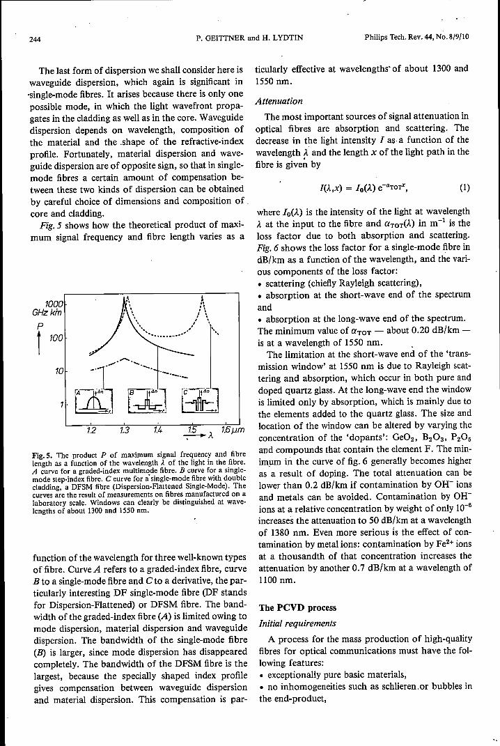
The last form of dispersion we shall consider here iswaveguide dispersion, which again is significant in-single-mode fibres. It arises because there is only onepossible mode, in which the light wavefront propa-gates in the cladding as well as in the core. Waveguidedispersion depends on wavelength, composition ofthe material and the .shape of the refractive-indexprofile. Fortunately, material dispersion and wave-guide dispersion are of opposite sign, so that in single-mode fibres a certain amount of compensation be-tween these two kinds of dispersion can be obtainedby careful choice of dimensions and composition of .core and cladding.Fig.5 shows how the theoretical product of maxi-
mum signal frequency and fibre length varies as a
1000GHz kinp
r 100
10
~À 1.6j.im1.3 1.41.2
Fig.5. The product P of maximum signal frequency and fibrelength as a function of the wavelength À of the light in the fibre.A curve for a graded-index multimode fibre. B curve for a single-mode step-index fibre. C curve for a' single-mode fibre with doublecladding, a DFSM fibre (Dispersion-Flattened Single-Mode). Thecurves are the result of measurements on fibres manufactured on alaboratory scale. Windows can clearly be distinguished at wave-lengths of about 1300 and 1550 nm.
function of the wavelength for three well-known typesof fibre. Curve A refers to a graded-index fibre, curveB to a single-mode fibre and C to a derivative, the par-ticularly interesting DF single-mode fibre (DF standsfor Dispersion-Flattened) or DFSM fibre. The band-width of the graded-index fibre (A) is limited owing tomode dispersion, material dispersion and waveguidedispersion. The bandwidth of the single-mode fibre(B) is larger, since mode dispersion has disappearedcompletely. The bandwidth of the DFSM fibre is thelargest, because the specially shaped index profilegives compensation between waveguide dispersionand material dispersion. This compensation is par-
ticularly effective at wavelengths' of about 1300 and1550 nm.
AttenuationThe most important sources of signal attenuation in
optical fibres are absorption and scattering. Thedecrease in the light intensity I as, a function of thewavelength À. and the length x of the light path in thefibre is given by
(1)
where Io(À.) is the intensity of the light at wavelengthÀ. at the input to the fibre and aTOT(À.) in m-I is theloss factor due to both absorption and scattering.Fig. 6 shows the loss factor for a single-mode fibre indB/km as a function of the wavelength, and the vari-ous components of the loss factor:• scattering (chiefly Rayleigh scattering),• absorption at the short-wave end of the spectrumand• absorption at the long-wave end of the spectrum.The minimum value of aTOT - about 0.20 dB/km -is at a wavelength of 1550 nm.The limitation at the short-wave end of the 'trans-
mission window' at 1550 nm is due to Rayleigh scat-tering and absorption, which occur in both pure anddoped quartz glass. At the long-wave end the windowis limited only by absorption, which is mainly due tothe elements added to the quartz glass. The size andlocation of the window can be altered by varying theconcentration of the 'dopants': Ge02, B20g, P205and compounds that contain the element F. The min-imum in the curve of fig. 6 generally becomes higheras a result of doping. The total attenuation can belower than 0.2 dB/km if contamination by OH- ionsand metals can be avoided. Contamination by OH-ions at a relative concentration by weight of only 10-6
increases the attenuation to 50 dB/km at a wavelengthof 1380 nm. Even more serious is the effect of con-tamination by metal ions: contamination by Fe2+ ionsat a thousandth of that concentration increases theattenuation by another 0.7 dB/km at a wavelength of1100 nm.
The PCVD process
Initial requirements
A process for the mass production of high-qualityfibres for optical communications must have the fol-lowing features:• exceptionally pure basic materials,• no inhomogeneities such as schlieren .or bubbles inthe end-product,

Philips Tech. Rev. 44, No. 8(9(10 PCVD PROCESS 245
• perfect control of the index profile in the radial di-rection,• less than 1% axial variation of refractive index,• high yield,• high process output,• high reproducibility and• high degree of automation.We shall now see how closely the Philips PCVD pro-cess can match this long list of requirements.
70dB/km.------------------.----,
Ct
t
1.0, ,,,05 \
\yUV
\\
02
07065 08 09 1.0 12 7.4_À
Fig.6. The loss factor a due to attenuation as a function of thewavelength Je of the light. UV the attenuation due to absorptionalone, at the short-wave end of the spectrum. IR the attenuationdue to absorption alone, at the long-wave end. Rs;02 the attenua-tion due to Rayleigh scattering in pure Si02. RSM the attenuationdue to Rayleigh scattering in a single-mode fibre. All the abovecurves are theoretical. The curve labelled TOTis the result of meas-urements and refers to the total attenuation in a single-mode fibre.It is approximately equal to the sum of the curves UV, IR and RsM.
The process
In spite of a great deal of effort, success in devel-oping conventional glass-forming processes such asthe double-crucible process [61 into a mass-productiontechnology for high-quality optical fibres has provedelusive. As mentioned earlier, the techniques thathave been used successfully are all based on the CVDprocess: reactive deposition from the gas phase. Thecharacteristic feature of this process is that glass con-
stituents such as Si02 and Ge02 are formed from thegases SiCI4, GeCl4 and 02. These gases react with oneanother, and the reaction products condense on thewalls of the enclosure in which the reaction takesplace.
The PCVD process was proposed and developed byPhilips Forschungslaboratorium Aachen in the earlyseventies [71, and was later taken over by the PhilipsGlass Product Group [81. The process makes use of aplasma that stimulates the reactions between the vari-ous gases. Fig. 7 shows the arrangement. The mostimportant components are the gas-supply system, thereaction zone inside a quartz-glass tube and the pumpsystem.
In the gas-supply system the gases SiCI4, GeCI4,C2F6 and O2 are metered with the aid of very accurate
MWC-o PL
Fig.7. a) Diagram of the PCVD process. OSS gas-supply system.MWC microwave cavity. PL plasma. PU pump system. 'CU controlunit. QT quartz-glass tube. F furnace. b) The laboratory arrange-ment. The cavity can be seen on the left of the furnace insulation;it is white and encloses the quartz-glass tube.
[6] H. M. J. M. van Ass, P. Geittner, R. G. Gossink, D. Küppersand P. J. W. Severin, The manufacture of glass fibres for opti-cal communication, Philips Tech. Rev. 36, 182-189, 1976.
[7] P. Geittner, D. Küppers and H. Lydtin, Low-loss optical fibresprepared by plasma-activated chemical vapor deposition(CVD), Appl. Phys. Lett. 28, 645-646, 1976.
[8] P. Matthijsse, The PCVD process for large scale productionof telecommunication fibres, Proc. SPIE 584, 11-15, 1986.

246 P. GEITTNER and H. LYDTIN
mass-flow controllers, mixed and fed into the reactionzone through a common feed. The reaction zone is en-closed by the tube of pure Si02, which functions as asubstrate for the light-guiding materialof the coreand the cladding. Around the tube there is a furnace.The gas mixture is fed through the reaction zone tothe pump system and passes through the plasma,where the gas molecules are fragmented into reactiveparticles.
The pressure in the reaction zone is 1 to 2 kPa (10 to20 mbar). A ring-shaped microwave cavity resonatorlocated around the Si02 tube excites the plasma. Thefrequency of the microwave energy is 2.45 GHz. Themaximum power in the cavity is 6 kW. The reactiveparticles react in the plasma and the condensable reac-tion products are deposited on the wall of the relativ-ely cold Si02 tube (about 1200 "C).
The special feature of the Philips PCVD process isthat the cavity continually moves to and fro at highspeed, taking the plasma with it inside the quartz-glass tube. A great many thin layers of glass form onthe inside of the tube, distributed uniformly over thelength. The thickness and the composition of anylayer can be varied by varying the rate of travel of thecavity and the flow rate of the gases. Almost any in-dex profile in 500 to 2000 extremely small steps can beobtained inside the Si02 tube in this way.
The useful part of the tube has a maximum lengthof 1 metre. The layers are constant in thickness andcomposition as a function of the length and the opti-cal properties hardly vary at all. After the unwantedends have been removed the tube is collapsed throughthe action of surface tension at a temperature of 2000to 2200 oe to form a solid rod; seefig. 8. This rod, the'preform', has a diameter of 15 to 30 mm and has thedesired radial optical structure, but on a larger scale,see title photograph. The preform is next drawn toform an optical fibre several kilometres long; seefig. 8c and d. The fibre is finally given a plastic protec-tive coating.
Significant advantages of the PCVD process arethat• the desired index profile can be approximated veryaccurately with such a large number of layers,• the reaction and deposition rates are almost inde-pendent of the ambient temperature,• yields are high,• the structure on the inside of the Si02 tube isformed at relatively low temperatures,• the energy in the cavity is transferred to the plasmawith virtually no losses, regardless of the thermalcharacteristics of the tube and the furnace,• the conditions hardly vary at all during the process,so that it is very suitable for the deposition of large
QT-I--
L-'r-
b
22000CPREF
22000C
F
Philips Tech. Rev. 44, No. 8/9/10
d
Fig.8. The process steps that ultimately provide a glass fibre foroptical communications. a) PCYD process. QT quartz-glass tube.L the layers deposited inside the tube by this process. b) Collapsingthe tube to form a 'preform' PREF. c) Drawing the preform into along thin glass fibre F. The regions at the highest temperature(2200 "C) are shown. d) Close-up of the 'neck' ofthe preform in thedrawing process.
numbers of layers with a high combined thickness.The process is therefore suitable in principle for themanufacture of large preforms for very long fibres.
Current resultsThe good results that can now be achieved for at-
tenuation, dispersion and process economics are large-ly due to:• a good understanding of the factors that affect thedeposition of Si02 and doping with Ge02 and F,• proper control of the index profile,• the avoidance of contamination by OH- and metalions,• effective control of the deposition rate, yield, repro-ducibility and dimensions of the preform.
Fig. 9 shows that the PCVD process will give rel-atively large variations in refractive index. These var-iations are larger than those that can be obtained withother processes. Only after we had gained a thoroughknowledge of the application of the dopants in Si02,and of the behaviour of these dopants as a function oftemperature, was it possible to reproduce the desired

Philips Tech. Rev. 44, No. 8/9/10 PCVD PROCESS
index profile sufficiently accurately in production [91.
This meant that by 1983 Philips were able to meet thespecifications set by Deutsche Bundespost, the WestGerman postal and telecommunications authority,for graded-index multimode fibres, and an order wasreceived for large quantities of these fibres. The
L1n
t 10-2
5 10 15%_C 0
F
Fig. 9. The variation /}.n in refractive index that can be obtained byintroducing a particular molecular concentration c of dopant. Thecurves for positive values of S n refer to Ge02 molecules, the curvesfor negative values refer to the concentration of F atoms. Thechain-dotted lines are the theoretically attainable values for com-plete incorporation of the dopants. The values that can be obtainedin practice are indicated by the measured points and refer to thefollowing process conditions: temperature 1200°C, pressure 16 to20 mbar, velocity of the microwave cavity O. [7 uils, external diam-eter of the quartz-glass tube 26 mm, internal diameter 23 mm. ForGe02 the deposition rate is 8 mg/s and the small filled trianglesrefer to a temperature of [240°C instead of [200 "C, For fluorinethe small filled circles correspond to a deposition rate of 8 mg/s andthe small filled triangles to a rate of 25 mg/s.
length-bandwidth product for the fibres had to be atleast 1.2 GHz km. At present the mean value for pro-duction graded-index fibres is 2.5 to 3 GHz km. For6070of the fibres the value is as high as 4 GHz km.
Although these results are very satisfactory, it wassoon clear that single-mode fibres for the wavelengthrange from 1300 to 1600 nm do have advantages overgraded-index fibres in bit rate and attenuation. This is
247
why most of the research since the early eighties hasbeen on single-mode fibres. It has also been foundthat the experience gained in the production ofgraded-index fibres is useful in the production ofsingle-mode fibres.
Fig. 10 shows the index profiles that could be ob-tained in preforms before they were drawn. Althoughnot all the profiles can be used in practice, the dia-gram clearly shows the rotational symmetries andradial accuracies that can be obtained nor Analysesof these profiles have indicated that the relative devia-
Fig. ID. Various measured 3-dimensional index profiles in the pre-forms used in the drawing process. The radial scales are not thesame in all the diagrams. The diagram at the lower right corre-spends to the DFSM fibre (profile C in fig.5). When fibres aredrawn from the preforms the shape of their index profiles is virtual-ly unchanged.
[9J P. Geittner, H. Hübner, H. Lydtin and H. Wilson, Influenceof central profile distortions on the bandwidth of GRIN multi-mode fibers, Proc. Conf. Opt. Fiber Commun. WG2, 90-9[,New Orleans 1983.
[IOJ H. Lydtin, PCVD: a technique suitable for large-scale fabrica-tion of optical fibers, J. Lightwave Techno!. LT-4, 1034-1038,1986.

248 P. GEITTNER and H. LYDTIN Philips Tech. Rev. 44, No. 8/9/10
tions from the ideal profile are smaller than 10/0. Theprofile at the lower right refers to a preform for theDFSM fibre mentioned earlier. In a wide wavelengthrange from 1320to 1600 firn this type of fibre has anextremely low time-delay difference due to dispersion,in relation to the spectral width of the light source:about 2 ps nm'" km". DFSM fibres have in the mean-time been included in the Philips product range.
Fig. 11 gives an impression of the spread in the at-tenuation at a wavelength of 1310 nm in fibres made
50%~-------------------------------'
10
30
20
o n03
Innn r-lr-l_
0.4 05 06dB/km-Cl.
Fig.11. Bar diagram showing the relative quantity Qrel of drawnfibre as a function of the measured loss factor ex due to attenuationat a wavelength of 1310nm. The diagram gives an impression oftheproduction spread in the current manufacturing process for single-mode fibres.
by the present production process. The mean attenua-tion of 0.35 dB/km is only 0.05 dB/km more than theminimum attainable value. The most important con-dition for obtaining low attenuation is the reductionof the contamination by OH- ions. Until recently thiswas a serious problem: investigations had shown thatin the PCVD process one in 80 of the hydrogen atomsin the reactive gas mixture was taken up by the layerstructure as an OH- ion. In the early eighties this high'take-up efficiency' led to increases in the attenuationof more than 100dB/km at a wavelength of 1380nm.This made it impossible to use glass optical fibres inthe 1300-nm transmission window. The problem ofOH- -ion contamination was solved by adding fluor-ine-containing gases such as C2F e to the reactive gasmixture. Fig. 12 shows the decrease in the attenua-tion at 1380 nm as a function of the concentration ofC2Fs in the gas mixture [111. The extra attenuationdue to OH- -ions at 1380 nm has recently been reducedto a minimum value of 0.1 dB/km.
For a total evaluation of the PCVD process it is notonly necessary to consider the physical properties ofthe manufactured fibres - it is also desirable to keepthe economic aspects in mind. After it had becomeclear that the process was suitable for manufacturingfibres with special index-profiles (see fig. 10), it waspossible to show that the improved understanding ofthe process had led to an improvement in the repro-ducibility. This opened the way to the automation ofthe manufacturing process. It was also possible toshow that deposition rates of the material in thequartz-glass tube of up to 3.3 grams per minute arepossible [121.
50dB/km..------------------,
\• 0\\:~5 0.. \\ .
. \2 \ ...
. g \
1 \ 0\05 \ ®\
\\\\02 \ \~\0.10 _C 2%
Fig. 12. The reduction ó.ex in the loss factor due to attenuation at awavelength of 1380 nm as a function of the molecular concen-tration c of C2Fs in the reactive gas mixture in the PCVD process.The measured values shown as open circles correspond to single-mode fibres and the filled circles to graded-index multimode fibres.The reduction in the attenuation is due to the reduction in the num-bers of OH- ions in the preform[ll].
OutlookOur future efforts will be concentrated on the con-
tinuous improvement of the PCVD process, with themain aim of manufacturing preforms equivalent to alonger fibre [131. The possibility of starting with a tubeof high-purity quartz glass for the light-guiding partof the fibre cladding is also being investigated. Theapplication of two tubes, one for the light-guiding

Philips Tech. Rev. 44, No. 8/9/10 PCVD PROCESS 249
part and one for the non-light-guiding part of thecladding, saves time in the PCVD process and in col-lapsing the tubes. The larger preform that is the resultof this improved process will give a fibre length ofabout 300 km per preform. So there is some evidencethat the preparation of the core and the light-guidingcladding material will be separated.There is a clear interest in single-mode fibres, since
their characteristics are much better than those of theother types of optical fibres. Within the 'family' ofsingle-mode fibres there is a noticeable trend towards
[11] P. Bachmann, P. Geittner, D. Leers, M. Lennartz and H. Wil-son, Low OH excess loss PCVD fibres prepared by fluorinedoping, Electron. Lett. 20, 35-37, 1984.
[12] P. Geittner, H.-J. Hagemann, J. Warnier and H. Wilson,PCVD at high deposition rates, J. Lightwave Techno). LT-4,818-822, 1986.
[18] P. Geittner, H.-J. Hagemann, H. Lydtin and J. Warnier,Hybrid technology for large SM fiber preforms, J. LightwaveTechno). LT-6, 1451-1454, 1988.
glass fibres with a complicated structure, in which var-ious kinds of dispersion are compensated. An ex-ample of this is the DFSM fibre mentioned earlier,which can be manufactured relatively easily by thePCVD process.
Summary. Optical fibres for telecommunications are either multi-mode fibres (step- or graded-index) or single-mode fibres. Single-mode fibres have either a stepped profile with a small core diameteror a complex layered refractive-index profile. The last type offibresare called DFSM (Dispersion-Flattened Single-Mode) fibres. Infibres of this type pulse broadening due to mode dispersion does notoccur and material dispersion and waveguide dispersion almostcompletely compensate one another. The Philips PCVD (Plasma-activated Chemical Vapour Deposition) process can be used for themanufacture of fibres with complicated index profiles. Closelycontrolled amounts of dopants such as Ge02 can be introducedinto the basic Si02 material at very low concentrations. The con-centration of OH- ions, which can introduce an intolerably high at-tenuation, has been greatly reduced by adding C2Fa to the reactivegas mixture. This reduced the attenuation due to OH- ions to aminimum value of 0.1 dB/km.