MANUFACTURING AND ANALYSIS OF BIOACTIVE GLASS FIBER, …
79
MANUFACTURING AND ANALYSIS OF BIOACTIVE GLASS FIBER, AND ITS APPLICATION IN BIOMEDICAL ENGINEERING SERGI ROCA PUERTAS Master of Science thesis Supervisor in home university: Manuel Laso Carbajo Supervisor in receiving university: Jonathan Massera
Transcript of MANUFACTURING AND ANALYSIS OF BIOACTIVE GLASS FIBER, …

MANUFACTURING AND ANALYSIS OF BIOACTIVE GLASS FIBER,
AND ITS APPLICATION IN BIOMEDICAL ENGINEERING
SERGI ROCA PUERTAS
Master of Science thesis
Supervisor in home university: Manuel Laso Carbajo Supervisor in receiving university: Jonathan Massera


AGRADECIMIENTOS
Gracias a todos y cada uno de las personas y situaciones que me han traído hasta aquí, hasta
este único y preciso momento en el que la entrega de la Master Thesis supone el fin de un ciclo
personal. Todo empezó en Septiembre de 2009 que tan lejano queda ya, ahora, 7 años después,
tras muchas historias, se da por concluido un proyecto en el que me embarque a ciegas, y que
paso a paso ha ido resultando ser sorprendente e inquietante.
Más concretamente, muchas gracias a todos los que me apoyaron y me permitieron ir un paso
más lejos y poder realizar este proyecto en la Universidad de Tampere TUT, y contar con un
equipo de especialistas que me han guiado a lo largo del mismo, enseñándome tanto de esta
temática, que era totalmente nueva para mí, como a trabajar en un laboratorio y poder contar
con un equipo multicultural con mucho que ofrecer.


MANUFACTURING AND ANALYSIS OF BIOACTIVE GLASS FIBER, AND ITS APPLICATION IN BIOMEDICAL ENGINEERING
SERGI ROCA PUERTAS
RESUMEN EJECUTIVO
En el presente trabajo de investigación, se pretende hacer un estudio de como varían las pro-
piedades térmicas, mecánicas y químicas de las fibras de vidrio bioactivo de fosfato en función
de su composición.
A rasgos generales se puede decir que en lo que consiste el trabajo es en la fabricación de vidrio
bioactivo, extrusión de fibras e inmersión de las mismas en un tampón químico llamado SBF
(Simulated Body Fluid). Luego se procede al análisis de los resultados, para ello se realizaron
diversos estudios en los que se incluyen la Espectroscopia de Absorción Atómica (AAS), Es-
pectroscopia en Transformada de Fourier (FTIR), ensayos mecánicos de tensión, Análisis Tér-
mico Diferencial (DTA).
Se podrá concluir con una comparación entre los diferentes tipos de vidrios para obtener fibras,
ventajas y desventajas entre unos y otros, y sobretodo profundizar y encaminar unos futuros
estudios para su desarrollo e inclusión en el mercado.
Introducción
El presente TFM se encarga de profundizar y colaborar en el avance y la evolución de los ma-
teriales biocerámicos (en concreto el vidrio bioactivo). Se entiende por biomaterial aquel que
puede interactuar con los tejidos del ser humano sin ser dañino. Podríamos encontrar dos tipos,
los bioactivos y los materiales biocompatibles. El estudio se centrará en los primeros. Son ma-
teriales que además de no tener ningún efecto perjudicial para el cuerpo humano, son favorables
para la regeneración del tejido óseo. Son reabsorbibles y favorecen la creación de Hidróxiapa-
tita.
Podemos encontrar tres tipos de vidrios bioactivos, de silicio, de fosfato, o de boro. Este pro-
yecto se ha centrado en los vidrios de fosfato, los cuales están en pleno desarrollo y aun se
ofrece un amplio campo de investigación. En concreto, el TFM se puede dividir en dos partes
claramente diferenciadas, el estudio y caracterización de diferentes vidrios de fosfato en función
de sus propiedades química para la elaboración de fibras. Y segundo, el estudio de cómo se
comportan dichas fibras dentro del fluido corporal mediante análisis in-vitro.
Procedimientos y análisis utilizados
A continuación, se enumeran los procesos que se han ido siguiendo, de la forma más ordenada
posible en relación con cómo se han hecho en la realidad, aunque realmente la mayor parte
estaban entrelazados y se solapaban:
Preparación y fundición de las muestras de vidrio.
Preparación de los compuestos iniciales.
Fundición del vidrio.
Extrusión de fibra de vidrio.

RESUMEN EJECUTIVO
ii ESCUELA SUPERIOR DE INGENIERIEROS INDUSTRIALES (UPM)
DTA.
Test SBF.
Inmersión temporal en SBF.
Análisis de PH de la muestra.
AAS.
Tensile test
FTIR.
Explicación teórico práctica y análisis de resultados de cada una de los pun-
tos previos.
Preparación de los vidrios, en forma de disco
El vidrio que más ha sido utilizado durante el proyecto ha sido llamado Sr50, además, se ha
experimentado con otro tipo de vidrios que comparten la misma composición base (Si5, Mg5,
Ti5 y Cu5). Su preparación partía de la mezcla de su composición, debiendo previamente for-
mar la materia prima. Un horno especializado para ello, y un programa de temperatura adecuado
a ellos creaban el vidrio fundido que posteriormente había que verter en el molde y mantenerlos
durante 5 horas a temperatura de recocido.
A continuación se comprueba la calidad del vidrio y si no hay problemas de cristalización, se
almacena para el siguiente paso.
Extrusión de la fibra de vidrio
Una vez se obtenían muestras de unos 25 g aproximadamente, se comprobaba que eran de ca-
lidad y no estaban parcialmente cristalizadas, se rompía en trozos grandes, una cantidad de unos
80 g de vidrio, y se depositaba en un nuevo crisol de platino, en este caso un crisol especial,
perforado por la parte inferior, para que el vidrio pueda caer cuando se está fundiendo. El Sr50
se posicionaba en el interior del horno, el cual tenía un conducto que permitía al vidrio caer del
crisol directamente al exterior.
La temperatura deseada se encuentra entre los 880 y los 900 C, como se pudo comprobar. Si
permanece a temperaturas inferiores, se cristaliza. Si, sin embargo, se expone a temperaturas
superiores, se funde demasiado y cae de golpe en forma líquida. El punto deseado es intermedio
entre sólido y líquido, lo suficiente líquido para que, por su propio peso, una primera gota caiga,
pero manteniendo la viscosidad que lo haga permanecer en el crisol.
Una vez obtenida la primera gota, esta arrastraba una fina fibra que la unía con el resto del
vidrio dentro del crisol. A continuación, se tracciona dicha fibra a un ritmo lo más constante
posible, para obtener una fibra uniforme, sin llegar a romperla.

MANUFACTURING AND ANALYSIS OF BIOACTIVE GLASS FIBER, AND ITS APPLICATION IN BIOMEDICAL ENGINEERING
SERGI ROCA PUERTAS iii
DTA: Differential Thermal Analysis.
El Análisis térmico diferencial es utilizado para comprobar las propiedades térmicas de cada
uno de los diferentes vidrios. Su funcionamiento queda explicado en la memoria, al igual que
para el resto de análisis. Una vez obtenido el análisis DTA, quedan fijos datos de relevancia de
cada uno de los vidrios como su temperatura de cristalización o temperatura de fusión. La má-
xima estabilidad en el perfil térmico, nos ofrece a su vez una mayor facilidad para extraer las
fibras.
SBF: Simulated body fluid
Queda mencionada la primera parte del trabajo, de extrusión de fibra de vidrio y comienza la
siguiente. Es la inmersión de las fibras en SBF, una solución tampón que simula las propiedades
de los fluidos corporales. Es una solución acelular con el mismo PH y que contiene los mismos
iones inorgánicos que el plasma sanguíneo, pero con falta de proteínas u otros constituyentes
orgánicos.
Inmersion de SC2, CC2, Sr50 y Sr5
Previamente, se contaba con dos tipos de fibra de vidrio distintos, ambos hechos con base de
Sr50, añadiéndoles un 2,50% molar de B2O3. Su composición se muestra en la tabla siguiente.
La diferencia entre ambos, como puede verse, es que el Cc2 cuenta además con el núcleo do-
pado de Cerio.
También se sumergieron las fibras obtenidas por extrusión de Sr50, y otras fibras con las que
se contaba, llamadas Sr5, de vidrio de silicio, con la siguiente composición, para comparar su
comportamiento con las fibras de fosfato.
El objetivo de sumergir las diferentes fibras en SBF por diferentes períodos de tiempo, es ver
como ese hecho afecta a las propiedades físicas de la fibra, estudiar su biodegradabilidad en
función del tiempo y ser capaces de caracterizar los diferentes vidrios para poder ajustar su
buen uso. Las fibras se sumergen por periodos de 6, 24, 48 y 72 h, y 1 y 2 semanas.
Medida del PH
Al finalizar el tiempo de inmersión de cada una de las muestras, se extraían del líquido con
mucho cuidado, se rociaban de etanol para limpiar bien las partículas de SBF y se secaban en
una incubadora durante 24 horas. El Líquido SBF resultante, se utiliza para medir su PH, y ver
cómo éste ha variado con el tiempo. El PH varía en función del tiempo de inmersión debido a
que a medida que el vidrio va reaccionando, se disuelve y aportan iones y moléculas de fosfato
cálcico al medio reactivo.

RESUMEN EJECUTIVO
iv ESCUELA SUPERIOR DE INGENIERIEROS INDUSTRIALES (UPM)
AAS: Atomic Absorption Spectroscopy. Medida de la concentración de iones Ca2+
Se prepara una disolución con el SBF resultante y agua (destilada), el objetivo es una disolución
ten-fold (decúpula), para reducir su concentración. Una vez obtenidas todas las muestras, se les
realizaba el análisis AAS con un espectrómetro Perkin Elmer AAnalyst 300, utilizando una
llama de aire-acetileno. De esta forma se cuantificaba la cantidad de iones Ca2+ libres en la
composición, y se analizan los resultados en busca de conocer la capacidad de degradación del
vidrio.
Ensayos mecánicos
Una vez que cada muestra (10 fibras de vidrio) era retirada por completo del SBF, como se ha
explicado antes, se procedía a realizar el ensayo mecánico de tracción. Para ello se utilizó una
Instron 4411. A través de los ensayos mecánicos se obtenía la gráfica de tensión y deformación
característica de cada fibra. Una a una, las 390 fibras fueron ensayadas, la curvas obtenidas,
procesadas y corregidas, mediante Origin, seleccionando solo la parte lineal de la curva, para
que el resto no influyera de forma negativa manipulando los resultados de la pendiente (Modulo
de Young).
FTIR: Fourier Transform Infrared Spectroscopy
Este método mide las transiciones vibracionales entre su estado fundamental y estados de exci-
tación. Estas transiciones son medidas mediante absorción o emisión de luz. El material a tratar
se expone a radiación IR. Parte de esa radiación simplemente pasa a través del material, y otra,
en cambio, es absorbida. Esta energía transmitida, supone el espectro buscado. Ya que no puede
haber dos moléculas diferentes que emitan el mismo espectro infrarrojo, a través de su lectura,
se puede observar perfectamente de qué tipo de sustancias estamos analizando. Es decir, FTIR
puede mostrarnos materiales desconocidos, es decir, mostrarnos la composición de dichos ma-
teriales.
Cada molécula, teniendo n átomos, tiene 3n grados de libertad. 6 de ellos son para la propia
molécula, y 3n-6 para los distintos modos de vibración que son: Estiramiento simétrico, tijere-
teo, aleteo, estiramiento asimétrico, balanceo y torsión.
La vibración IR puede ser activa o inactiva, dependiendo si hay absorción del espectro IR o no.
En este ensayo, el FTIR se realizó por medio de una máquina Perkin Elmer FTIR spectrum.
Todo el espectro fue grabado en una banda desde 600 a 2000 cm-1. FTIR se aplicó a todas las
muestras de Sc2 y Cc2 para 0 y 72 horas, y 1, 2 y 3 semanas, ya que para tiempos de inmersión
menores a 72 horas, no se observó cambio.
El objetivo, y los resultados obtenidos nos acercan a conocer la evolución de la composición
de las fibras en función del tiempo de inmersión, lo cual nos acerca al conocimiento de la for-
mación de fosfato cálcico, necesario para la regeneración del hueso y formación de apatita.

MANUFACTURING AND ANALYSIS OF BIOACTIVE GLASS FIBER, AND ITS APPLICATION IN BIOMEDICAL ENGINEERING
SERGI ROCA PUERTAS v
Conclusiones y futuras líneas de investigación
Es este trabajo de investigación se ha contribuido al estudio de la fibra de vidrio de una forma
muy exhaustiva.
Se ha profundizado en el estudio de creación, por medio de la extrusión, de fibras de vidrio con
nuevas composiciones, distintas a las que hoy en día se utilizan. Métodos que aún no están muy
desarrollados, y que necesitan de nuevas y numerosas pruebas. El análisis térmico (DTA), nos
deja claro cuáles son las composiciones más apropiadas para ellos, por una mayor estabilidad
energética del vidrio. Para ello se ha estudiado el vidrio protagonista de este estudio, Sr50. Pese
al pequeño cambio en la composición (5% molar), se observaron grandiosos cambios en sus
propiedades térmicas. Como conclusión se deduce que debería seguir profundizándose en la
creación de fibras de vidrio del tipo Si5 y Ti5, las cuales pueden suponer una muy buena apuesta
futura, a un precio razonable, ya que serían las más fáciles de extrudir.
De forma independiente, se han analizado las propiedades de las fibras de fosfato fabricadas en
este mismo estudio, de Sr50, y de otras, también de base de Sr50, con una composición ligera-
mente modificada, Sc2 y Cc2.
Sc2 y Cc2 tienen un muy buen comportamiento reactivo al cuerpo humano. Se degradan de
forma gradual, reducen sus propiedades físicas también de forma gradual. De este estudio se
puede analizar, en función del tipo de aplicación biomédica, el tipo de fibra más conveniente.
Como refuerzo para materiales compuestos, queda claro, que la fibra de vidrio puede jugar un
papel fundamental en la fuerza de dichos materiales. En este estudio se observó la dureza y
Modulo de Young en función del tiempo de inmersión, el cual permanece prácticamente cons-
tante hasta el paso de cierto tiempo.
Como complemento, se está produciendo, y se prevé un cambio aun mayor, un incremento del
uso de materiales no metálicos en implantes. Para ello es necesaria la creación de nuevos bio-
materiales compuestos. En este caso, las fibras de fosfáto cálcico, no solo proveen al implante
de una mayor fuerza, sino que apoyan con sus propiedades osteoconductivas (capacidad de un
material para actuar como un substrato en el cual las células puedan adherirse y desarrollar sus
funciones).
Para finalizar se concluye afirmando que este tipo de vidrios bioactivos, ofrece una gran opor-
tunidad para el desarrollo de nuevos materiales compuestos y técnicas, como materiales cons-
tructivos en ingeniería de tejidos.

RESUMEN EJECUTIVO
vi ESCUELA SUPERIOR DE INGENIERIEROS INDUSTRIALES (UPM)

MANUFACTURING AND ANALYSIS OF BIOACTIVE GLASS FIBER, AND ITS APPLICATION IN BIOMEDICAL ENGINEERING
SERGI ROCA PUERTAS
RESUMEN
Alcance
En el presente trabajo de investigación, se pretende hacer un estudio de como varían las pro-
piedades térmicas, mecánicas y químicas de las fibras de vidrio bioactivo de fosfato en función
de su composición.
A rasgos generales se puede decir que en lo que consiste el trabajo es en la fabricación de vidrio
bioactivo, extrusión de fibras e inmersión de las mismas en un tampón químico llamado SBF
(Simulated Body Fluid). Luego se procede al análisis de los resultados, para ello se realizaron
diversos estudios en los que se incluyen la Espectroscopia de Absorción Atómica (AAS), Es-
pectroscopia en Transformada de Fourier (FTIR), ensayos mecánicos de tensión, Análisis Tér-
mico Diferencial (DTA).
Se podrá concluir con una comparación entre los diferentes tipos de vidrios para obtener fibras,
ventajas y desventajas entre unos y otros, y sobretodo profundizar y encaminar unos futuros
estudios para su desarrollo e inclusión en el mercado.
Introducción
Los materiales utilizados en biomedicina para realizar implantes, y que, en definitiva, tienen
contacto directo con el interior del cuerpo humano, se hacen llamar biomateriales. Aunque el
uso de materiales en implantes ha sido aplicado durante siglos, es en el siglo XX cuando real-
mente se produjeron los primeros grandes avances. El objetivo de ellos es mejorar la salud de
la gente que ha sufrido accidentes, problemas óseos de nacimiento, o desordenes de la edad, a
través de la ayuda a la reconstrucción de los huesos.
Los avances más importantes en el campo de los biomateriales, se ha producido gracias al desa-
rrollo de Biocerámicos y vidrios bioactivos. Pueden considerarse dos tipos de biomateriales:
Biocompatibles y Bioactivos. Los primeros son materiales que liberan compuestos No-tóxicos
en el cuerpo humano, si modificar, en ningún aspecto su composición. Los bioactivos, en cam-
bio, tienen un efecto positivo en el tejido óseo y favorecen su regeneración. Estos últimos,
siendo reabsorbibles (Se descomponen y se asimilan por el cuerpo) desaparecen del cuerpo por
ser degradables hidrolítica y enzimáticamente. Es muy importante su caracterización, y debido
a que, en fases iniciales de investigación, no se permite ensayar con animales, es necesario
realizar análisis in-vitro.
Podemos encontrar tres tipos de vidrios bioactivos, de silicio, de fosfato, o de boro. Este trabajo
se centrará en el estudio de vidrios del fosfato, y se hará una ligera comparación con estudios
previos de otros vidrios de silicio.

RESUMEN
ii ESCUELA SUPERIOR DE INGENIERIEROS INDUSTRIALES (UPM)
Literatura y Teoría
Biomateriales, huesos y tejido óseo
El objetivo de los biomateriales es adaptarse al cuerpo humano para desempeñar una función
reparadora cumpliendo con los requerimientos mecánicos, térmicos y biocompatibles del
cuerpo (tensiones de cizalladura, Modulo de Young, coeficiente térmico…).
El esqueleto es el principal sostenedor del cuerpo humano. Está diseñado para soportar todo
tipo de esfuerzos de la vida cotidiana del ser humano, incluida la constante fuerza de la grave-
dad. Su composición puede ser dividida en dos, cortical y trabecular. La primera constituye el
80%wt de la composición del esqueleto. El 70% del hueso es de origen mineral (Ca2+, PO43-
son sus principales constituyentes y CO32- se muestra en menor proporción). La parte orgánica
contiene agua, proteínas (colágeno de tipo I) y otras proteínas. Todo este tipo de compuestos
que lo conforman, hacen que el hueso se considere un material compuesto.
El fosfato cálcico que constituye el hueso es Hidróxiapatita, Ca10(PO4)6(OH)2(HA). Su for-
mación, gracias a la reacción con el vidrio de fosfato que ha sido analizado en este estudio,
supone la regeneración del hueso.
El hueso tiene un módulo de Young que abarca un rango de 17 a 24 GPa, dependiendo del
hueso, sexo, edad en tracción axial.
Vidrios de fosfato y propiedades
El vidrio está definido como un sólido rígido, amorfo con una viscosidad más alta de 1013 poise.
Puede haber vidrios compuestos por los siguientes óxidos B2O3, SiO2, GeO2, P2O3, As2O3, Sb2O3,
In2O3, Tl2O3, SnO2, PbO2 and SeO2. Dentro de todos estos, los óxidos capaces de formar vidrio
son tres, y los vidrios se catalogarán dentro de esos tres, SiO2, P2O5 and B2O3. Siendo los vidrios
de silicio los más utilizados.
Los vidrios de fosfato están constituidos de cadenas de estructura polimérica de tetraedros de
fosfato unidos entre ellos a través de átomos de Oxígeno. Los tetraedros son de PO4, y usual-
mente se dividen en grupos Qn desde n=0 hasta n=3. Q0 se corresponde con el orto-fosfato
aislado. Q1 son los tetraedros de comienzo y fin de la cadena de fosfato. Q3 son la unidad rama.
En dichos casos, n sería el número de oxígenos “puente” por cada tetraedro. Por ello, Q2 es una
unidad que se encuentra en medio de la cadena polimérica, con un tetraedro a cada lado.

MANUFACTURING AND ANALYSIS OF BIOACTIVE GLASS FIBER, AND ITS APPLICATION IN BIOMEDICAL ENGINEERING
SERGI ROCA PUERTAS iii
Procedimientos y análisis utilizados
A continuación, se enumeran los procesos que se han ido siguiendo, de la forma más ordenada
posible en relación con cómo se han hecho en la realidad, aunque realmente la mayor parte
estaban entrelazados y se solapaban:
Preparación y fundición de las muestras de vidrio.
Preparación de los compuestos iniciales.
Fundición del vidrio.
Extrusión de fibra de vidrio.
DTA.
Test SBF.
Inmersión temporal en SBF.
Análisis de PH de la muestra.
AAS.
Tensile test
FTIR.
Explicación teórico práctica y análisis de resultados de cada una de los pun-
tos previos.
Preparación de los vidrios, en forma de disco
El vidrio que más ha sido utilizado durante el proyecto ha sido llamado Sr50, además, se ha
experimentado con otro tipo de vidrios. La composición de cada uno de los vidrios de fosfato
con los que se ha trabajado se muestra a continuación:
•Sr50: 50 P2O5 – 10 Na2O – 20 SrO – 20 CaO
•Si5: 45 P2O5 – 10 Na2O – 20 SrO – 20 CaO – 5 SiO2
•Cu5: 45 P2O5 – 10 Na2O – 20 SrO – 20 CaO – 5 CuO
•Mg5: 45 P2O5 – 10 Na2O – 20 SrO – 20 CaO – 5 MgO
•Ti5: 45 P2O5 – 10 Na2O – 20 SrO – 20 CaO – 5 TiO2
Como se puede comprobar, todos guardan la composición del Sr50, salvo que se les añade un
5% molar de Si, Cu, Mg o Ti. Para su preparación se precisaba de Sr(PO3)2, Ca(PO3)2 y NaPO3.
Los dos primeros había que prepararlos haciendo uso de CaCO3 y SrCO3, como se muestra en
la siguiente tabla y siguiendo un programa térmico de temperatura máxima de 1100 C, con una
duración de 50 h.

RESUMEN
iv ESCUELA SUPERIOR DE INGENIERIEROS INDUSTRIALES (UPM)
Ca(PO3)2 Sr(PO3)2 50 g 50 g
CaCO3 (NH4)2HPO4 SrCO3 (NH4)2HPO4
15.023 g 26.894 g 12.636 g 33.3502 g
15.023 g 26.894 g 12.636 g 33.3502 g
Finalmente, los compuestos químicos necesarios para elaborar 30 g de cada uno de dichos vi-
drios se muestran en la tabla siguiente.
Kind of Glass
Sr50 Si5 Ti5 Mg5 Cu5
Raw material Composition (grams) for 30 g of glass
Ca(PO3)2 10.88935 9.965877 9.872275 10.06126 9.873777
Sr(PO3)2 13.50371 12.35853 12.24245 12.47682 12.24432
NaPO3 5.606939 5.864506 5.809424 5.920637 5.810308
CaCO3 0.719584 0.712825 0.726471 0.712934
SrCO3 1.061392 1.051423 1.071551 1.051583
SiO2 0.863963
TiO2 1.137619
MgO 0.585091
CuO 1.133227
Con dichas composiciones, y utilizando un crisol de patino, se sigue
un programa de calor especifico (se puede encontrar en la sección 4.2
Glass melting), y una vez terminado, se vierte el vidrio fundido en un
molde de carbono, y se le somete a un nuevo programa térmico de
recocido de 5 horas a 350 C. En la imagen se muestra un disco de 30 g
de Ti5
Se fundió también un vidrio de silicio nombrado B50 para comparar las facilidades de extru-
sión. Su composición y procedimientos están explicados en la memoria.
Extrusión de la fibra de vidrio
Una vez se obtenían muestras de unos 25 g aproximadamente, se comprobaba que eran de ca-
lidad y no estaban parcialmente cristalizadas, se rompía en trozos grandes, una cantidad de unos
80 g de vidrio, y se depositaba en un nuevo crisol de platino, en este caso un crisol especial,
perforado por la parte inferior, para que el vidrio pueda caer cuando se está fundiendo. El Sr50
se posicionaba en el interior del horno, el cual tenía un conducto que permitía al vidrio caer del
crisol directamente al exterior.
La temperatura deseada se encuentra entre los 880 y los 900 C, como se pudo comprobar. Si
permanece a temperaturas inferiores, se cristaliza. Si, sin embargo, se expone a temperaturas

MANUFACTURING AND ANALYSIS OF BIOACTIVE GLASS FIBER, AND ITS APPLICATION IN BIOMEDICAL ENGINEERING
SERGI ROCA PUERTAS v
superiores, se funde demasiado y cae de golpe en forma líquida. El punto deseado es intermedio
entre sólido y líquido, lo suficiente líquido para que, por su propio peso, una primera gota caiga,
pero manteniendo la viscosidad que lo haga permanecer en el crisol.
Una vez obtenida la primera gota, esta arrastraba una fina fibra que la unía con el resto del
vidrio dentro del crisol. A continuación, se tracciona dicha fibra a un ritmo lo más constante
posible, para obtener una fibra uniforme, sin llegar a romperla.
DTA: Differential Thermal Analysis.
El análisis térmico tiene como objetivo estudiar una propiedad física en una sustancia, en fun-
ción de la temperatura. En este caso, se estudia la cantidad de energía necesaria para mantener
la muestra a cierta temperatura comparado con otra muestra de la que previamente se saben sus
propiedades. Se miden cambios en la absorción o emisión de energía y se comparan con la
muestra. Este análisis muestra los cambios de fase del material. Es interesante en este estudio,
para controlar los puntos de cristalización y fusión del vidrio, y así saber qué materiales tendrán
mejor comportamiento y menos tendencia a la cristalización a la hora de producir las fibras.
Para realizar el análisis térmico diferencial y poder interpretar bien las propiedades térmicas de
cada uno de los vidrios, era necesario, por medio de un mortero, convertir el vidrio en pequeñas
partículas de entre 125 y 250 micrómetros. Para ello se hizo uso de un filtro con el que diferen-
ciar las partículas.
30 mg de vidrio, en un crisol diminuto, se ensayaban térmicamente en el horno
DTA, Netszch F1 JUPITER con el procedimiento explicado previamente.
El resultado obtenido fueron las gráficas mostradas en la siguiente figura. Una por una, se su-
perpusieron utilizando Origin (software utilizado para el procesamiento de datos a lo largo de
todo el proyecto):
Para explicar la gráfica, se prestará atención a la curva rosa, Mg5. El pico más alto, que se
encuentra a aproximadamente 620 C, corresponde con la temperatura de cristalización Tb. El
pico mínimo absoluto, situado en 700 es la “liquidous temperature” y es el punto endotérmico
donde el vidrio comienza a fundirse. Para una mayor estabilidad a la hora de fundir de nuevo
el vidrio para poder extraer las fibras, se busca que la curva DTA sea lo más lisa posible, con
poco cambio energético.
Es por ello, que los mejores vidrios para extraer fibras son el Si5 y el Ti5 (entre los estudiados).
Aun así, solo se extrajo fibra del Si5 ya que no se disponía de un crisol perforado de silicio, y
en el de platino resulta imposible porque se forma aleación entre los dos metales.

RESUMEN
vi ESCUELA SUPERIOR DE INGENIERIEROS INDUSTRIALES (UPM)
100 200 300 400 500 600 700 800 900 1000 1100
-35
-30
-25
-20
-15
-10
-5
0
5
10
15
20
25
30
35
40
45
DS
C (
mW
)
Temperatures (°C)
Sr50
Ti5
Si5
Mg5
Cu5
SBF: Simulated Body Fluid
Es una solución tampón utilizada en ensayos in-vitro, para simular la degradación de los mate-
riales dentro del cuerpo humano. Es una solución acelular con el mismo PH y que contiene los
mismos iones inorgánicos que el plasma sanguíneo, pero con falta de proteínas u otros consti-
tuyentes orgánicos.
Su preparación siempre tuvo que ser muy precisa y está detalladamente explicada a lo largo de
la memoria. Tiene una duración aproximada de 5 horas en total. Y el objetivo final es ajustar
su PH al del cuerpo humano en 7,4.
Inmersión de SC2, CC2, Sr50 y Sr5
Previamente, se contaba con dos tipos de fibra de vidrio distintos, ambos hechos con base de
Sr50, añadiéndoles un 2,50% molar de B2O3. Su composición se muestra en la tabla siguiente.
La diferencia entre ambos, como puede verse, es que el Cc2 cuenta además con el núcleo do-
pado de Cerio.
Sample
Diameter
(μm) P2O5 CaO SrO Na2O B2O3 CeO2
Sc2 125 125 47.50% 20% 20% 10% 2.50% -
Sc2 250 250 47.50% 20% 20% 10% 2.50% -
Cc2 125 125 47.50% 20% 20% 10% 2.50% 0.25%
Cc2 250 250 47.50% 20% 20% 10% 2.50% 0.25%
*Core doped with Cerium (mol%)

MANUFACTURING AND ANALYSIS OF BIOACTIVE GLASS FIBER, AND ITS APPLICATION IN BIOMEDICAL ENGINEERING
SERGI ROCA PUERTAS vii
También se sumergieron las fibras obtenidas por extrusión de Sr50, y otras fibras con las que
se contaba, llamadas Sr5, de vidrio de silicio, con la siguiente composición, para comparar su
comportamiento con las fibras de fosfato.
•Sr5: 53.85SiO2 1.72P2O5 16.77CaO 22.66Na2O 5SrO
El objetivo de sumergir las diferentes fibras en SBF por diferentes períodos de tiempo, es ver
como ese hecho afecta a las propiedades físicas de la fibra, estudiar su biodegradabilidad en
función del tiempo y ser capaces de caracterizar los diferentes vidrios para poder ajustar su
buen uso.
Antes de su inmersión en SBF, se procede a medir su diámetro, para después comprobar, tam-
bién, cómo estos varían. Las fibras se sumergen por periodos de 6, 24, 48 y 72 h, y 1 y 2 sema-
nas. En total, para cada uno de los períodos, se sumergen 10 fibras de 15 centímetros cada una.
Cada grupo de 10 fibras, considerémoslo como una muestra, estaba clasificado por tipo de vi-
drio y diámetro. Sc2 y Cc2 fueron ensayados con diámetros de 125 y 250 micrómetros.
Medida del PH
Al finalizar el tiempo de inmersión de cada una de las muestras, se extraían del líquido con
mucho cuidado, se rociaban de etanol para limpiar bien las partículas de SBF y se secaban en
una incubadora durante 24 horas. El Líquido SBF resultante, se utiliza para medir su PH, y ver
cómo éste ha variado con el tiempo. Para ello se usa una máquina Mettler To-ledo Seven-
Multi™ pH/conductivity meter.
Los resultados se plasmaron en las gráficas siguientes, y fueron analizados.
Como se puede comprobar, en las tres muestras de fibras de vidrio de fosfato, el PH tiende a
disminuir de acorde con el tiempo que las fibras permanecen inmersas. Esto es debido a que las
fibras, a medida que van reaccionando, se disuelven y aportan iones y moléculas de fosfato
cálcico al medio reactivo.
7,24
7,26
7,28
7,3
7,32
7,34
7,36
7,38
7,4
7,42
0h 6h 24h 48h 72h 1 w 2 w 3 w
PH
PH SBF SC2/CC2
PH Sc2 125 microns
PH Sc2 250 microns
PH Cc2 125 microns
PH Cc2 250 microns
PH Sr50

RESUMEN
viii ESCUELA SUPERIOR DE INGENIERIEROS INDUSTRIALES (UPM)
Aunque no se ha incluido su gráfica en este resumen, para el Sr5, el PH, sin embargo, se veía
incrementado con el paso del tiempo. Debido a que simplemente se desintegran las fibras, pero
existe formación de dicho fosfato cálcico.
AAS: Atomic Absorption Spectroscopy. Medida de la concentración de iones Ca2+
Se prepara una disolución con el SBF resultante y agua (destilada), el objetivo es una disolución
ten-fold (decúpula), para reducir su concentración. Una vez obtenidas todas las muestras, se les
realizaba el análisis AAS con un espectrómetro Perkin Elmer AAnalyst 300, utilizando una
llama de aire-acetileno. De esta forma se cuantificaba la cantidad de iones Ca2+. De la misma
forma que en el análisis de PH, como comprobamos en la siguiente figura, el contenido de Ca2+
disminuye en función del tiempo en los vidrios de fosfato. Al contrario ocurre de nuevo con el
Sr5 (vidrio de silicio), de nuevo.
Una vez más, este descenso de concentración de Ca2+ es debido a la formación de fosfato cál-
cico, que era lo que buscábamos, la prueba de su desintegración bajo la formación del mismo,
para facilitar la formación de Hidróxiapatita. Se puede comprobar en esta figura.
La degradación de las fibras, y su correspondiente formación de fosfato cálcico, es mayor para
las fibras sin dopaje de Cerio (Sc2).
Ensayos mecánicos
Una vez que cada muestra (10 fibras de vidrio) era retirada por completo del SBF, como se ha
explicado antes, se procedía a realizar el ensayo mecánico de tracción. Para ello se utilizó una
Instron 4411. A través de los ensayos mecánicos se obtenía la gráfica de tensión y deformación
característica de cada fibra. Una a una, las 390 fibras fueron ensayadas, la curvas obtenidas,
procesadas y corregidas, mediante Origin, seleccionando solo la parte lineal de la curva, para
que el resto no influyera de forma negativa manipulando los resultados de la pendiente (Modulo
de Young).
0
1
2
3
4
5
6
6h 24h 48h 72h 1 w 2 w 3 w
Ca2
+co
nce
ntr
atio
n (
mg/
l)
Ca (mg/l) Sc2/Cc2
Sc2 125microns Ca(mg/l)
Sc2 250microns Ca(mg/l)
Cc2 125microns Ca(mg/l)
Cc2 250microns Ca(mg/l)

MANUFACTURING AND ANALYSIS OF BIOACTIVE GLASS FIBER, AND ITS APPLICATION IN BIOMEDICAL ENGINEERING
SERGI ROCA PUERTAS ix
Finalmente se obtienen gráficas comparativas para Modulo de Young (E) y Tensión admisible
a máxima carga. A continuación se muestra el Modulo de Young E, para Sc2 y Cc2 de 250
micrómetros.
Como se puede comprobar, el Modulo de Young no varía prácticamente en función del tiempo
de inmersión, sino que se mantiene constante. Era exactamente el resultado que buscábamos,
que indica que el material sigue siendo el mismo pese a su degradación.
Aparece en cambio factor muy curioso a partir de las 72 h o 1 semana. La gráfica comienza a
dividirse en dos. Hay ciertas fibras que tienen un comportamiento totalmente distinto al resto,
y su E disminuye. Como se observa en la gráfica, a dichas fibras se les ha llamado Sc2 y Cc2
system.
Este resultado, lo que nos indica, es que las fibras más degradadas, con mayor cantidad de
fosfato cálcico en la superficie, como parte de un sistema fibra+fosfato, tienden a comportarse
con otras propiedades físicas. Sin embargo, sigue habiendo otras que han sido menos atacadas
por la solución tampón, que siguen comportándose como el material que eran. Es decir, la for-
mación de fosfato cálcico no es uniforme para todas las fibras).
En este caso, son las fibras de Sc2, en comparación con las de Cc2 las que ofrecen unas mejores
propiedades mecánicas en función del tiempo de inmersión. Sr5 y Sr50 mostraron muy malas
propiedades físicas, que no sobrepasó su posible estudio por más de 24 horas.
FTIR: Fourier Transform Infrared Spectroscopy
Este método mide las transiciones vibracionales entre su estado fundamental y estados de exci-
tación. Estas transiciones son medidas mediante absorción o emisión de luz. El material a tratar
se expone a radiación IR. Parte de esa radiación simplemente pasa a través del material, y otra,
en cambio, es absorbida. Esta energía transmitida, supone el espectro buscado. Ya que no puede
haber dos moléculas diferentes que emitan el mismo espectro infrarrojo, a través de su lectura,
0
10000
20000
30000
40000
50000
60000
0 6 24 48 72 1w 2w 3w
E M
Pa
YOUNG MODULUS ESC2/CC2 250 micrometers
E SC2 system
E SC2
E CC2 system
E CC2

RESUMEN
x ESCUELA SUPERIOR DE INGENIERIEROS INDUSTRIALES (UPM)
se puede observar perfectamente de qué tipo de sustancias estamos analizando. Es decir, FTIR
puede mostrarnos materiales desconocidos, es decir, mostrarnos la composición de dichos ma-
teriales.
Cada molécula, teniendo n átomos, tiene 3n grados de libertad. 6 de ellos son para la propia
molécula, y 3n-6 para los distintos modos de vibración que son: Estiramiento simétrico, tijere-
teo, aleteo, estiramiento asimétrico, balanceo y torsión.
La vibración IR puede ser activa o inactiva, dependiendo si hay absorción del espectro IR o no.
En este ensayo, el FTIR se realizó por medio de una máquina Perkin Elmer FTIR spectrum.
Todo el espectro fue grabado en una banda desde 600 a 2000 cm-1. FTIR se aplicó a todas las
muestras de Sc2 y Cc2 para 0 y 72 horas, y 1, 2 y 3 semanas, ya que para tiempos de inmersión
menores a 72 horas, no se observó cambio.
A continuación se mostrará el ejemplo del Sr50, que fue la que mejor comportamiento tuvo al
realizar el análisis, y es más fácil observar los cambios producidos en el material debidos a la
inmersión.
Una vez realizado el FTIR, y para analizar los resultados, el espectro IR fue normalizado apro-
ximadamente en 880 cm-1, donde se presenta el mayor pico.
Se pueden apreciar 3 zonas perfectamente diferenciadas en el rango de 600 a 1400 cm-1:
Vibración de grupos de fosfato PO2 “no-puente” o Q2 en 1400-1150 cm-1.
Región terminal de grupos P-O y PO3, Q0 y Q1, en 1150-900 cm-1.
Vibración de los grupos P-O-P, 900-700 cm-1
Se pueden comprobar, con este previo y breve resumen de cómo se distribuye el fosfato en el
espectro IR, los resultados siguientes. Se produce un incremento de los grupos Q1 y descenso
de los grupos Q2. Este hecho significa que la estructura del vidrio está sufriendo una despoli-
merización de las cadenas de fosfato desde Q2 a Q1, es decir, se están rompiendo dichas cadenas,
y, por tanto, formando cadenas más cortas (mayor número de Q1 indica mayor número de ex-
tremos de cadenas).

MANUFACTURING AND ANALYSIS OF BIOACTIVE GLASS FIBER, AND ITS APPLICATION IN BIOMEDICAL ENGINEERING
SERGI ROCA PUERTAS xi
700 800 900 1000 1100 1200 1300 1400
0,0
0,2
0,4
0,6
0,8
1,0
A.U
.
Wavenumber (cm-1)
Sr50-0
Sr50-24
Sr50-48
Sr50-72
Sr50-1w
Son grandes noticias, ya que el objetivo de los vidrios bioactivos, es el de disolverse en el
cuerpo humano.
Los resultados son variados para el resto de vidrios, mostrando algunos de ellos ciertas anoma-
lías, las cuales sería preciso seguir investigando, para ver si se repiten.
El vidrio de silicio Sr5, muestra un espectro totalmente distinto al de los de fosfato, que puede
ser apreciado en la “Figure 5.20. FTIR spectra of Sr5 glass fibers, as function of the immersion
time.” Unos resultados bastante buenos en los que se aprecia muy bien. La curva se normaliza
en este caso para 960 cm-1. Es este cado las variaciones se muestran en el incremento de con-
centración de unidades de SiO4 y descenso de unidades de Si-O-.
Conclusiones y futuras líneas de investigación
Es este trabajo de investigación se ha contribuido al estudio de la fibra de vidrio de una forma
muy exhaustiva.
Se ha profundizado en el estudio de creación, por medio de la extrusión, de fibras de vidrio con
nuevas composiciones, distintas a las que hoy en día se utilizan. Métodos que aún no están muy
desarrollados, y que necesitan de nuevas y numerosas pruebas. El análisis térmico (DTA), nos
deja claro cuáles son las composiciones más apropiadas para ellos, por una mayor estabilidad
energética del vidrio. Para ello se ha estudiado el vidrio protagonista de este estudio, Sr50. Pese

RESUMEN
xii ESCUELA SUPERIOR DE INGENIERIEROS INDUSTRIALES (UPM)
al pequeño cambio en la composición (5% molar), se observaron grandiosos cambios en sus
propiedades térmicas. Como conclusión se deduce que debería seguir profundizándose en la
creación de fibras de vidrio del tipo Si5 y Ti5, las cuales pueden suponer una muy buena apuesta
futura, a un precio razonable, ya que serían las más fáciles de extrudir.
De forma independiente, se han analizado las propiedades de las fibras de fosfato fabricadas en
este mismo estudio, de Sr50, y de otras, también de base de Sr50, con una composición ligera-
mente modificada, Sc2 y Cc2.
Sc2 y Cc2 tienen un muy buen comportamiento reactivo al cuerpo humano. Se degradan de
forma gradual, reducen sus propiedades físicas también de forma gradual. De este estudio se
puede analizar, en función del tipo de aplicación biomédica, el tipo de fibra más conveniente.
Como refuerzo para materiales compuestos, queda claro, que la fibra de vidrio puede jugar un
papel fundamental en la fuerza de dichos materiales. En este estudio se observó la dureza y
Modulo de Young en función del tiempo de inmersión, el cual permanece prácticamente cons-
tante hasta el paso de cierto tiempo.
Como complemento, se está produciendo, y se prevé un cambio aun mayor, un incremento del
uso de materiales no metálicos en implantes. Para ello es necesaria la creación de nuevos bio-
materiales compuestos. En este caso, las fibras de fosfáto cálcico, no solo proveen al implante
de una mayor fuerza, sino que apoyan con sus propiedades osteoconductivas (capacidad de un
material para actuar como un substrato en el cual las células puedan adherirse y desarrollar sus
funciones).
En este estudio también se ha comprobado que, en principio, las fibras de vidrio de fosfato
cálcico, no suponen ningún peligro, ni riesgo potencial para el cuerpo humano ya que no se
libera ningún tipo de ion dañino al diluirlos en SBF.
Para finalizar se concluye afirmando que este tipo de vidrios bioactivos, ofrece una gran opor-
tunidad para el desarrollo de nuevos materiales compuestos y técnicas, como materiales cons-
tructivos en ingeniería de tejidos.

SERGI ROCA PUERTAS
CONTENTS
1. INTRODUCTION ..................................................................................................... 1
2. OBJECTIVES ........................................................................................................... 3
3. THEORY AND LITERATURE REVIEW ............................................................... 5
3.1 Biomaterials .................................................................................................... 5
3.2 Bone and hard tissue ....................................................................................... 5
3.2.1 Bone mechanical properties ............................................................. 6
3.3 Glasses and their properties ............................................................................ 7
3.4 Phosphate glasses ........................................................................................... 8
3.5 Differential Thermal Analysis (DTA) ............................................................ 9
3.6 SBF ............................................................................................................... 10
3.7 FTIR ............................................................................................................. 10
3.7.1 FTIR Spectrum absorption of hydroxyapatite (HAp) .................... 13
3.8 AAS .............................................................................................................. 13
3.9 Mechanical properties of glass fibers ........................................................... 14
4. EXPERIMENTAL PROCEDURE ......................................................................... 17
4.1 Preparing calcium and strontium phosphate ................................................ 17
4.2 Glass melting ................................................................................................ 18
4.3 Glass crushing .............................................................................................. 19
4.4 Making fibers ............................................................................................... 20
4.4.1 Sr50 ................................................................................................ 21
4.4.2 Si5 .................................................................................................. 21
4.4.3 B50 ................................................................................................. 21
4.5 Making SBF ................................................................................................. 21
4.6 SBF Test ....................................................................................................... 22
4.6.1 Mechanical test ............................................................................... 23
4.6.2 Tensile Test .................................................................................... 25
4.7 PH Measurement .......................................................................................... 26
4.8 Atomic Absorption Spectroscopy ................................................................ 26
4.9 Fourier transform infrared spectroscopy ...................................................... 27
4.10 Differential thermal analysis ........................................................................ 27
5. RESULTS................................................................................................................ 29
5.1 DTA .............................................................................................................. 29
5.2 SBF Test ....................................................................................................... 30
5.2.1 AAS and PH measurement ............................................................. 30
5.2.2 Mechanical test ............................................................................... 32
5.2.3 FTIR ............................................................................................... 37
6. CONCLUSIONS AND FUTURE LINES OF RESEARCH .................................. 43
7. CORPORATE SOCIAL RESPONSIBILITY ......................................................... 45
8. TIMING AND BUDGET........................................................................................ 47

ii ESCUELA SUPERIOR DE INGENIERIEROS INDUSTRIALES (UPM)
LIST OF SYMBOLS AND ABBREVIATIONS
AAS Atomic absorption spectroscopy
DTA Differential thermal analysis
FTIR Fourier transform infrared spectroscopy
HAp Hydroxyapatite
SBF Simulated Body Fluid
Glasses:
Sr50 50 P2O5 – 10 Na2O – 20 SrO – 20 CaO
Si5 45 P2O5 – 10 Na2O – 20 SrO – 20 CaO – 5 SiO2
Cu5 45 P2O5 – 10 Na2O – 20 SrO – 20 CaO – 5 CuO
Mg5 45 P2O5 – 10 Na2O – 20 SrO – 20 CaO – 5 MgO
Ti5 45 P2O5 – 10 Na2O – 20 SrO – 20 CaO – 5 TiO2
B50 26,93 SiO2 – 26,93 B3O3 – 22,66 NaO2 – 21,76 CaO – 1,72 P2O5
Sr5 53.85SiO2 1.72P2O5 16.77CaO 22.66Na2O 5SrO

MANUFACTURING AND ANALYSIS OF BIOACTIVE GLASS FIBER, AND ITS APPLICATION IN BIOMEDICAL ENGINEERING
SERGI ROCA PUERTAS 1
1. INTRODUCTION
Materials used to be in contact with human tissue are known as biomaterials. This material
application in the human body is not new. It is something that has been made for centuries
although the real successful advantages take part in the 20th century [1] [2]. Objective of them
is to improve health in people with accidental, birth or age disorders by reconstructing the miss-
ing or broken part of the human body.
These biomaterials can be divided in two different groups, biocompatible and bioactive mate-
rials. While biocompatible materials release non-toxic substances to the body that do not alter
the constitution of it, bioactive materials have a positive impact on the tissue e.g. the forming
of the bone on the proximities of the scaffold. Then, resorbable materials completely disappear
from your body after a period of time by being hydrolytically or enzymatically degradable.
Characterization of biomaterials is fundamental, and as they cannot be proven in animals at
least in their earlier stage of development, the best option until now are in-vitro cell tests.
The ideal biomaterial for applying in bone replacement or fixation would be one that adapts
itself to the repairing process. That its absorption does not exceed the rate of bone formation
and also this ratio goes weakening the scaffold at the same time that bone tissue gets stronger.
The use of these kinds of material that promote the bone regeneration in exchange of the tradi-
tional screws and plates that remain constant would mean an improvement not just economi-
cally but in people’s health.
Problems with metal and alloy materials in scaffolds comes because, even though the help in
the healing process, their stiffness is much higher than the bone itself, which made needs of
mandatory removal of the material after the bone is fixed.
Recently (from 1906), the use of ceramics and glasses in scaffolds is raising and has opened a
new science of study in biomedical field. Most common bioactive glass used is Bioglass®.
Silicate glass which has been proved that is stable to hydrolysis due to its silica content, but still
creates osteoblast cell attachment and proliferation
In the other hand, phosphate glasses constitute an alternative to previous silica glasses. Their
properties make them soluble in water and adjustable by altering glass composition. Hence,
they have a big potential in being applied as a bioresorbable implant materials. As good char-
acteristics we can mention their processibility (Low melting glass transition and melting tem-
peratures), and their adjustable solubility. [3]

INTRODUCTION
2 ESCUELA SUPERIOR DE INGENIERIEROS INDUSTRIALES (UPM)

MANUFACTURING AND ANALYSIS OF BIOACTIVE GLASS FIBER, AND ITS APPLICATION IN BIOMEDICAL ENGINEERING
SERGI ROCA PUERTAS 3
2. OBJECTIVES
The goal of this study is the development of new phosphate glasses by studying their chemical,
thermal and mechanical properties comparing them between each other’s and with other previ-
ous studies in order to improve the current implementation of biomaterials in bioresorbable
bone replacement and degradable scaffolds in tissue engineering. The use of degradable mate-
rials for bone repairing and regeneration is a great advance in surgery. The point is approach
the phosphate properties of the glass to a bone holding by its strength and being enough de-
gradable in accordance to bone healing process.
Phosphate glasses with suitable additives in their composition can be adjusted in terms of crys-
tallization tendency or solubility. The release of particles from these glasses has to be always
constituted by those which are already present in the human body. Optimization of the degra-
dation rate improves biocompatibility and bioactivity in the material.
Taking in account silica glasses and comparing them with phosphate ones, the phosphate
glasses have higher crystallization tendency. This tendency has to be reduced as much as pos-
sible in order to improve producibility.
In this thesis, the process made was as follow. First of all, manufacturing of the glasses. This
has been a task included during all the process of the research, every week, every day. Once
that some samples of glass were made, DTA studies the thermal properties of them in order to
determine which are easier to draw (for making fiber) according with a more stable energy
during the melting process. Once the glasess are chosen due to be the ones that fit the best
profile, was time to draw the first fibers.
When all the fibers were ready, they were immersed in SBF (simulated body fluid) to prove
their biocompatibility and bioactivity. Afterwards, the glass fiber was tested in a tensile ma-
chine, the chemical properties to determine biodegradability were tested using AAS and FTIR.
The goal of the thesis is being able to specify which glasses have the best properties and try to
understand why. Make a comparison between them. And describe which could be a good way
to keep researching them in the most efficient way, rejecting the ones that, here, we will prove,
are not the best option.

OBJECTIVES
4 ESCUELA SUPERIOR DE INGENIERIEROS INDUSTRIALES (UPM)

MANUFACTURING AND ANALYSIS OF BIOACTIVE GLASS FIBER, AND ITS APPLICATION IN BIOMEDICAL ENGINEERING
SERGI ROCA PUERTAS 5
3. THEORY AND LITERATURE REVIEW
3.1 Biomaterials
Nowadays, a very large variety of sophisticated materials have been used in biomedicine. From
some years ago, new polymers and metals started to be used in medicine as scaffolds. From that
moment, the use of these kind of materials is more and more commonly used, hence, new tech-
nologic advances need to be reached.
A biomaterial is a nondrug element ready to get into a physiological system for improving or
substituting the functions of the body tissues or organs. The bio material must fit perfectly in
the system, hence it has to have the mechanical, thermal and chemical requirements from the
body as shear, strain, Young’s modulus, temperature coefficient, being compatible with the
biological body system, inert… Biomaterials can be polymers and plastics, metals, ceramics or
treated natural materials. They most important property of the biomaterials is the biocompati-
bility; in some applications the contact of them with the implant is necessary, for example using
the fibrous capsule to hold the implant from moving [3], [4].
The use of materials in surgery is coming from long time ago. Already, in the pre Christian era,
replacements for broken bones were used. During this ancient times bronze and copper implants
were mainly utilized for repairing bones. The risk of poisoning was low as the Cu2+ ions circu-
lating in the body were overwhelmed once the copper element had completely dissolved in the
body fluid when the fractures were repaired.
Until mid-nineteenth century bronze or copper were not considered as an option for implants.
A wide range of new sophisticated materials are currently studied and used in biomedical fields
as implants, it just occurs some years ago. [5].
3.2 Bone and hard tissue
Human skeleton is constituted by bones. Bones are a the main important mechanical holder of
the human body, therefore, it is defined to resist stress providing internal support again the
external human body forces including the constant gravity. Its composition depends on the kind
of bone, age, sex and physiological conditions.
Bone composition can be divided in cortical bone and trabecular. Cortical bone is 80% in mass
of the whole body skeleton.
Bones are composed by around 70%wt of mineral which is almost the 40% of the bone volume.
These mineral constitutors are mainly calcium Ca2+ and phosphate PO43- and also a small part
of carbonates CO32-. The organic matrix constitutes around 40%wt. It is constituted by around
THEORY AND LITERATURE REVIEW
6 ESCUELA SUPERIOR DE INGENIERIEROS INDUSTRIALES (UPM)
90%wt, 30% of the volume, protein collagen type I. Non collagenous proteins complete the rest
of the small percentage composition, they are small part, but also important for the bone char-
acteristics and functions. Water is the 25% of the bone volume. [6]
The calcium phosphates that constitute the bone are hydroxyapatite, Ca10(PO4)6(OH)2 (HA).
Figure 3.1 Hydroxyapatite structure [6]
Apatite in bones is characterized by containing fluorine, sodium and magnesium in small
amounts. The different amount of constituents, apatite, collagen and water, all of them with
completely different properties, makes bones a composite material. [6] [7]
3.2.1 Bone mechanical properties
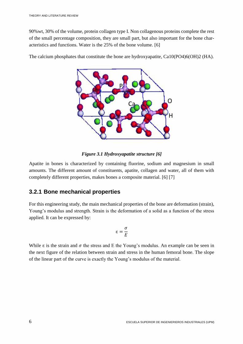
For this engineering study, the main mechanical properties of the bone are deformation (strain),
Young’s modulus and strength. Strain is the deformation of a solid as a function of the stress
applied. It can be expressed by:
ɛ =𝜎
𝐸
While ɛ is the strain and 𝜎 the stress and E the Young’s modulus. An example can be seen in
the next figure of the relation between strain and stress in the human femoral bone. The slope
of the linear part of the curve is exactly the Young’s modulus of the material.

MANUFACTURING AND ANALYSIS OF BIOACTIVE GLASS FIBER, AND ITS APPLICATION IN BIOMEDICAL ENGINEERING
SERGI ROCA PUERTAS 7
Figure 3.2. Stress-strain curves of human femoral bone. Adapted from Evans (1969). [8]
The term strength represents the stress at the breaking point.
For the cortical bone the Young’s modulus values are in the range from 17 to 24 GPa depending
on the age, sex, location of the bone, and many other factors. The tensile and compressive
strengths for bones in axial direction are around 130 and 200 MPa respectively. While in per-
pendicular direction to the axe are 50 and 130 MPa respectively. [7] [9]
3.3 Glasses and their properties
Glass is defined as an amorphous, rigid solid with a viscosity higher than 1013 poise. Next
oxides can be made into glass: B2O3, SiO2, GeO2, P2O3, As2O3, Sb2O3, In2O3, Tl2O3, SnO2,
PbO2 and SeO2 [10].
Oxides that are able to form glasses are going to be divided in three groups namely glass-for-
mers, intermediates and modifiers, in accord with their single strength bond value [11]. The
mainly primary glass formers are SiO2, P2O5 and B2O3 with the ability of forming single com-
ponent glass. The most used currently are the silica glasses. They have the highest melting
point, hence, in the main composition are added other components in order to reduce this tem-
perature. Phosphate glasses have the problem of being very reactive and hygroscopic, so the
aim of adding other components is increase its durability. The structure of phosphate and silica
glasses network forming tetrahedral can be notices in the figure below.

THEORY AND LITERATURE REVIEW
8 ESCUELA SUPERIOR DE INGENIERIEROS INDUSTRIALES (UPM)
Figure 3.3. Phosphate and silica tetrahedron.
Figure 3.4.Glass characterization examples [10]
3.4 Phosphate glasses
Phosphate glasses are a network of phosphate tetrahedron bonded each other using the bonding
corner sharing atoms of oxygen. Oxygen atoms linking two phosphate tetrahedrons are called
bridging atoms, and all who does not link it are non-bridging atoms.
Phosphate glasses are made by PO4 tetrahedrons which are usually divided in Qn groups. The
phosphate can be bonded in 4 different ways which compound each of the 4 different groups,
Q0 would be the isolated orthophosphate group, Q1 is the end unit, Q2 is the middle unit, and
finally the branch unit Q3. For Qn, n means the number of bridging oxygen atoms per tetrahe-
dron. For example, Q2 is linking two phosphate tetrahedrons in a polymeric phosphate chain,
being Q1 as the end of the chain. Next Figure 3.5 represents very well how are these phosphates
bonded with oxygen atoms [12] [13].
Figure 3.5. Phosphate tetrahedral units. Oxygen atoms (pink) connected to phosphorus at-
oms (blue). Q3 crosslinking units; Q2 middle units; Q1 end units; Q0 isolated units. [13]

MANUFACTURING AND ANALYSIS OF BIOACTIVE GLASS FIBER, AND ITS APPLICATION IN BIOMEDICAL ENGINEERING
SERGI ROCA PUERTAS 9
3.5 Differential Thermal Analysis (DTA)
Thermal analyses are made in order to study a physical property of a substance as a function of
temperature. In this case, Differential Thermal analysis study the amount of energy needed to
keep the sample to a chosen temperature comparing with another reference sample which we
know previously its properties. It is applied the same heat treatment for both of them, and it is
measured the energy needed to keep them at exactly the same temperature.
DTA involves heating or cooling down the desired sample and another reference sample in the
same conditions. The differences between the temperatures of the inert reference and the sample
are measured and plotted as a function of time or temperature. The changes on the sample,
absorption or emission of energy are measured comparing them with the reference sample.
DTA can measure phase changes, hence, its curve present changes and can be appreciate on it
the transition points for the sample material as is wanted in this thesis for the having knowledge
of the crystallization or melting temperatures of the glass.
The Differential Thermal Analysis instrument is composed by the next components shown in
the picture below:
Thermocouples and ceramic or metallic crucible for putting the study material inside.
PLC, controlling the heating program.
Furnace.
Recording system.
Figure 3.6. Structure of a DTA instrument.
The two containers are filled with the sample and with the inert reference. It works due to the
deflection of the voltmeter depending on the temperature variation [14].

THEORY AND LITERATURE REVIEW
10 ESCUELA SUPERIOR DE INGENIERIEROS INDUSTRIALES (UPM)
3.6 SBF
It is mentioned before that one of the most recent and important advantage made by the ortho-
pedic industry is producing biomaterials able to replace bone in human body. It is known that
this is possible because these biomaterials (bioactive glasses, glass ceramics…) and the bone
tissue are biocompatible. When these materials are incorporated in the bone in the human body,
they form a fibrous tissue interface layer. The apatite forming ability of the biomaterials can be
measured using Simulated Body Fluid (SBF) in-vitro and the results can predict the ability of
these biomaterials in-vivo [15].
SBF has been used in hundreds of researches when need to evaluate the performance of new
biomaterials for replacing a bone. The test in-vitro is always an excellent pre-test.
Methods for testing SBF in-vitro have been standardized [16]. Their ion concentrations similar
to the blood are represented in the next Table 3.1.
Table 3.1. Ion concentration of SBF comparing with human blood plasma according to the
ISO standard [16]
Concentration (10-3 mol)
Ion SBF (PH=7.4) Blood plasma (PH=7.2-7.4)
Na+ 142 142
K+ 5 5
Mg2+ 1.5 1.5
Ca2+ 2.5 2.5
Cl- 147.8 103
HCO3- 4.2 27
HPO42- 1 1
SO42- 0.5 0.5
3.7 FTIR
Infrared spectroscopy measures the vibrational transitions between the ground and the first ex-
ited states. It could be measure by absorption or emission of light [17].
Fourier Transform Infrared is the most common method of infrared spectroscopy. The sample
material is exposed to a IR radiation. Some of the radiation is passed through the sample and
some is absorbed. The transmitted radiation and the absorbed one is the spectrum result and it
gives a fingerprint of the structure of the sample. Depending on the infrared spectrum, the struc-
tural composition of the sample can be known because cannot be two different molecular struc-
tures emitting the same infrared spectrum [18]. Therefore, FTIR can define unknown materials;
determine the composition of a sample and its consistency. Figure 3.7 shows how it works.

MANUFACTURING AND ANALYSIS OF BIOACTIVE GLASS FIBER, AND ITS APPLICATION IN BIOMEDICAL ENGINEERING
SERGI ROCA PUERTAS 11
FTIR has many benefits used for chemical analysis of calcium phosphate components. Basi-
cally the resultant spectrum obtained gives information about the location, intensity and other
properties for the desired wavelength [19].
Figure 3.7. FTIR, main principle of who it works [18].
The wavelength resultant is the wavelength transmitted without taking in consideration the
wavelength absorbed by the material, so its structure is known from now.
In order to explain better how it works and how it is going to be used first of all, has to be
explained the electromagnetic spectrum. IR waves travel at light speed and they have a specific
range of wavelength and frequency which is from 8x10⁻⁵ cm to 1x10⁻² cm. Wavelength is the
measured distance between two peaks in a wave, λ. It is inversely proportional to the frequency
ν. While c is the speed of light.
λ = c/ν
Being photons packs of energy, when they strike a molecule, depending on its energy, they can
be absorbed by it which will produce a reaction. The energy absorbed by the molecules under
the IR is enough to make atoms vibrate but not to make electronic transitions.
The result vibration transitions give information about how atoms are bonded between each
other.
Every molecule having n atoms has 3n degrees of freedom. 6 of them are for the molecule itself.
Hence, there are 3n-6 of them for vibrational modes which can be divided in stretching, twist-
ing, rocking, bending and scissoring. Next Figure 3.8 shows the main vibrational modes.

THEORY AND LITERATURE REVIEW
12 ESCUELA SUPERIOR DE INGENIERIEROS INDUSTRIALES (UPM)
Figure 3.8. Vibrational modes of a molecule. [20]
Vibration IR can be active or inactive depending if there is absorption of the IR spectrum of
not. Symmetrical bonds have zero dipole moment and when they are stretched the dipole is still
zero, hence, there is no absorption of energy. It is inactive IR vibration.
In the next Figure 3.9 will be shown an example on how IR spectrometry works in order to
determine the different kind of bond between the molecules using molecular vibrations pro-
duced by IR absorption. Next example shows the infrared spectrum of methanol. Being finger-
print the region from 600-1400 cm-1, the most complex and informative part of the spectrum
that contains wagging, twisting, scissoring and rocking vibrations [20].
Figure 3.9. Infrared spectrum of methanol, which shows O-H, C-H and C-O stretching ab-
sorptions from several bending modes. [20]

MANUFACTURING AND ANALYSIS OF BIOACTIVE GLASS FIBER, AND ITS APPLICATION IN BIOMEDICAL ENGINEERING
SERGI ROCA PUERTAS 13
3.7.1 FTIR Spectrum absorption of hydroxyapatite (HAp)
Hydroxyapatite (HAp) Ca10(PO4)6(OH)2 is the most significant mineral phase belonging to the
bones and bone tissues. The most common component groups in the IR spectrum of HAp are
OH-, HPO42- and PO4
3-.
PO43- are the most interesting for this project and form and intensive IR absorption at 560, 600
and 1000-1100 cm-1. More specifically HAc present bands of PO43- that have the following
vibration modes: 460 cm-1 has v2 vibration mode. 560-600 have v4 bending vibrational mode.
960 has v1 vibrational mode. 1020, 1120, 1040 have v3 Bending vibrational mode (Destain-
ville, et al., 2003), (Han J-K., et al., 2006). Next Figure 3.10 shows the IR spectrum of HAc.
Figure 3.10. Typical FTIR spectrum of hydroxyapatite (Ratner, 2004). [19]
3.8 AAS
It is a technique used for determining the concentration of an element in the sample. This
method can be used to determine 70 kind of different elements in a solution or even in the solid
samples.
AAS main principle is based on that metal atoms absorb characteristic wavelengths and this
absorption is the same as the emission spectra of this particular metal [21].
The technique works taking in account that free atoms (gas) generated in an atomizer can absorb
radiation at specific frequency. These atoms absorb radiation and make transitions to higher
electronic energy levels. Depending on the amount of absorption the concentration is deter-
mined. The instrumentation is composed by the following parts; Hollow Cathode Lamp, De-
tector, Nebulizer, Atomizer and Monochromator.
Hollow cathode lamp is the radiation source most common in AAS.

THEORY AND LITERATURE REVIEW
14 ESCUELA SUPERIOR DE INGENIERIEROS INDUSTRIALES (UPM)
The Nebulizer sucks up liquid at a controlled rate and convert the sample in an aerosol spray
for introduce it into the flame.
The Atomizer converts the elements in atomic state by separating the particles into individual
molecules and breaking them in atoms. In the case of this thesis, the atomizer was flame atom-
izer. The flame is formed by mixing oxidant gas and fuel.
The Monochromator is used to separate all of thousands of lines and select the specific wave-
length absorbed by the sample by excluding all the other wavelengths. It makes possible the
determination of the selected element in presence of the others.
Finally the light goes to the Detector which converts the light into an electrical signal as a
function of the intensity. [22]
Figure 3.11. Structure of AAS instrument. [23]
3.9 Mechanical properties of glass fibers
Fibers are the principal load carrying component of a composite. The characteristics of the fiber
significantly influence the effective mechanical and damage properties of the composite fabri-
cated from it. The mechanical and damage properties of individual constituents, that is fiber
and matrix, are essential in a micromechanical analysis of composites for effective properties
and damage evaluation. These experiments are conducted on single filaments. In most of the
micromechanical analysis the mean or average properties are used. However, the variation of
properties can have significant effect on the final results. Hence, one needs statistical infor-
mation about the individual constituent properties for detailed micromechanical analysis. In the
present study another emphasis is given to create the statistical data for the behavior of these
fibers. The experimental procedures to determine the axial Young’s modulus and ultimate axial
tensile strength of single fiber have been explained in detail in this work. This has been possible
following Standard Test Method for Tensile Strength and Young’s Modulus of Fibers, ASTM
C1557. [24]
Even being more recommended making these studies using specific statistic models to study
the mechanical properties. In this case, due to the lack of time sources and specimens, the me-
chanical test will follow the standard process.

MANUFACTURING AND ANALYSIS OF BIOACTIVE GLASS FIBER, AND ITS APPLICATION IN BIOMEDICAL ENGINEERING
SERGI ROCA PUERTAS 15
Tensile test will give us information about Young’s modulus which is a mechanical property of
linear elastic solid materials. It relates stress and strain in a material.
E=𝜎
ℇ=
𝐹𝐿𝑜
𝐴𝑜∆𝐿
This modulus is a measure of the stiffness of the material. As It is shown in the picture below,
the slope of the first linear ramp indicates the Young’s modulus. In the test, we are going to use
the average of these slopes (for each group of samples) in order to determine the modulus. We
will also obtain values related with stress at maximum load force. The purpose of that is know-
ing how the mechanical properties decrease in function of the time they spend immersed on the
SBF, which will indicate the degradation that they experiment.
Figure 3.12. Young’s Modulus

THEORY AND LITERATURE REVIEW
16 ESCUELA SUPERIOR DE INGENIERIEROS INDUSTRIALES (UPM)

MANUFACTURING AND ANALYSIS OF BIOACTIVE GLASS FIBER, AND ITS APPLICATION IN BIOMEDICAL ENGINEERING
SERGI ROCA PUERTAS 17
4. EXPERIMENTAL PROCEDURE
4.1 Preparing calcium and strontium phosphate
The preparation of Sr50, the phosphate glass most used during this thesis, needed to obtain
Sr(PO3)2 and Ca(PO3)2 previously. For the preparation of these two chemical were used
Ca(CO3)2, Sr(CO3)2 and (NH4)2HPO4 following the next heating program and quantities. Each
week were made 50 grams of Sr(PO3)2 and 50 grams of Ca(PO3)2 in 4 different crucibles by
mixing the components in as follows in the next table.
Table 4.1. Amount in grams of the raw materials needed for making Ca(PO3)2 and Sr(PO3)2
Ca(PO3)2 Sr(PO3)2 50 g 50 g
CaCO3 (NH4)2HPO4 SrCO3 (NH4)2HPO4
15.023 g 26.894 g 12.636 g 33.3502 g
15.023 g 26.894 g 12.636 g 33.3502 g
The heating program is shown in the figure below. It means an amount of 49.2 hours. Hence,
the easiest solution was to leave the components in the oven all the weekend in order to avoid
having problems with people working in the laboratory while the ammonium could be in the
air. Therefore, this procedure was followed every Friday.
Figure 4.1. Heating program for preparing Ca(PO3)2 and Sr(PO3)2.
0
100
200
300
400
500
600
700
800
0 3:40 15:40 22:20 34:20 38 50
Temperature (C)

EXPERIMENTAL PROCEDURE
18 ESCUELA SUPERIOR DE INGENIERIEROS INDUSTRIALES (UPM)
4.2 Glass melting
Glasses were made by melting mixtures of chemicals as oxides and phosphates. First of all, the
calculation of the chemical quantities for each glass had to be made. Afterwards, measuring is
the next step with a scale keeping the tolerance of ±5 mg. Once the mixture is ready and homo-
geneous by mixing in the mortar, the batch is placed into a platinum crucible or in a glass silica
crucible (in case of glasses with titanium or cupper in order to avoid the formation of alloys
between the crucible and the glass).
According with the DTA results and the difficulty to get fibers from Sr50, the glasses made
were:
• Sr50: 50 P2O5 – 10 Na2O – 20 SrO – 20 CaO
• Si5: 45 P2O5 – 10 Na2O – 20 SrO – 20 CaO – 5 SiO2
• Cu5: 45 P2O5 – 10 Na2O – 20 SrO – 20 CaO – 5 CuO
• Mg5: 45 P2O5 – 10 Na2O – 20 SrO – 20 CaO – 5 MgO
• Ti5: 45 P2O5 – 10 Na2O – 20 SrO – 20 CaO – 5 TiO2
Next Table 4.2 shows the needed amount of raw materials for each glass. As it has been said
before, the phosphates were made apart. The main structure of the glass is Sr50. Afterwards,
due to the difficulties to draw the fibers; the other glass compositions consist in a small variation
of Sr50 in order to make it more stable improving the thermal properties.
Table 4.2. Raw material quantities for each glass composition
Kind of Glass
Sr50 Si5 Ti5 Mg5 Cu5
Raw material Composition (grams) for 30 g of glass
Ca(PO3)2 10.88935 9.965877 9.872275 10.06126 9.873777
Sr(PO3)2 13.50371 12.35853 12.24245 12.47682 12.24432
NaPO3 5.606939 5.864506 5.809424 5.920637 5.810308
CaCO3 0.719584 0.712825 0.726471 0.712934
SrCO3 1.061392 1.051423 1.071551 1.051583
SiO2 0.863963
TiO2 1.137619
MgO 0.585091
CuO 1.133227

MANUFACTURING AND ANALYSIS OF BIOACTIVE GLASS FIBER, AND ITS APPLICATION IN BIOMEDICAL ENGINEERING
SERGI ROCA PUERTAS 19
The crucible will be placed in an electric furnace following the corresponding heating program.
It is taking the crucible in at 600 C and waiting for 30 minutes, after increase to 1100 C with a
ramp approximately of 20 C/min and leaving the crucible inside for another 30 minutes, after-
wards mix the glass and leaving it for another 5 minutes. Later, casting in the carbon mold and
leave the solidified glass annealing for 5 hours at 350 C.
Figure 4.2. Ti5 glass disc after melting process.
Despite from all of these phosphate glasses, a silica glass B50 was also made in order to also
try to make fibers and see how the easy or difficult it is. The glass formula is written next.
B50: 26,93 SiO2 – 26,93 B3O3 – 22,66 NaO2 – 21,76 CaO – 1,72 P2O5
Below in the next table is shown the chemicals needed for preparing B50 glass.
Table 4.3. Raw material quantities for B50
Kind of Glass
B50
Raw material Composition (grams) for 40 g of glass
SiO2 10.174
CaCO3 11.528
Na2CO3 15.102
H3BO3 20.935
CaHPO4 2H2O 3.721
4.3 Glass crushing
Afterwards, DTA will be explained. For that it is need to have the glass crushed in small parti-
cles between 125 and 250 micrometers.

EXPERIMENTAL PROCEDURE
20 ESCUELA SUPERIOR DE INGENIERIEROS INDUSTRIALES (UPM)
The glass was crushed with a mortar and filtered in sieves with a vibration machine. Grains
were classified in 250-500, 125-250 and 50-125 micrometers, even though for this study are
only going to be useful the ones said before, the rest could be used in future researches.
Figure 4.3. Ti5 glass during the crushing process
4.4 Making fibers
One of the main points of this thesis was being success in getting bioactive glass fibers drawn
from melting. For this purpose, was needed a special furnace with a tube in the bottom part, in
order to draw the fibers from there when the glass is in the right melted point. The structure of
the furnace can be appreciated in the Figure 4.4.
Figure 4.4. Structure of the furnace used for drawing fibers from melting
The process was at it follows. After collecting between 60 or 80 grams of the desired glass, it
was placed in a platinum crucible with small holes in the bottom. The platinum crucible was
placed in the furnace and looking with a mirror trying to appreciate the state of the glass, the
temperature was being modified until the first drop comes.

MANUFACTURING AND ANALYSIS OF BIOACTIVE GLASS FIBER, AND ITS APPLICATION IN BIOMEDICAL ENGINEERING
SERGI ROCA PUERTAS 21
4.4.1 Sr50
It was the main glass composition tried to be drawn. It was also the most difficult because was
not easy finding the right point in which it was not solidified but either not completely liquid.
Many times all the glass was wasted without success due to the high temperature after waiting
for hours the first drop to form. Still, fibers were obtained the last time and they could be ana-
lyzed. These difficulties to draw fibers made us have to try new glass compositions varying
slightly the composition of Sr50 in order to have more energy stability improving the thermal
properties of the glass.
4.4.2 Si5
Si5, looking at the Thermal properties obtained from DTA, together with Ti5, they seem to be
the ones that have the most stable thermal properties form the crystallization point to the melting
one. The impossibility of drawing fibers using Platinum crucible with Titanium (they would
form an alloy and ruin the crucible) made us choose Ti5 as the next glass to try.
Surprisingly, fibers were obtained from the first try. They were really easy to get in a tempera-
ture of 875 C. The problem was that they were crystallized. A second try was done in order to
verify that it was not a problem of the impurity of the glass. This time, the glass was introduced
at a higher temperature (920 C) in order to not let it dangerously remain at a crystallization
temperature. Afterwards, the temperature was adjusted again to 875. And for the second time,
the fibers were really easy to obtain but still all the glass was crystallized.
4.4.3 B50
Finally, non-phosphate but silica glass was tried for drawing fibers from melting and compare
the pros and contras. It was the best of the glasses to be drawn. Fibers were obtained at first
chance at a temperature of 870 C. They were obtained in no longer than 15 minutes and they
were not crystallized.
4.5 Making SBF
SBF was first used, introduced and create by Kokubo. It is really important, as was said before,
the creation of apatite in the surface of the scaffolds in order to help the material to cohere and
be able to be part of the bone. SBF is used to test biocompatibility in vitro of biomaterials and
it helps to study the formation of apatite in the surface of scaffold.
The steps followed for the preparation of 1 liter of SBF are described below:
Put 700 ml of distilled water in a container and place it in the mixer covering it with
parafilm.
Add following chemicals:

EXPERIMENTAL PROCEDURE
22 ESCUELA SUPERIOR DE INGENIERIEROS INDUSTRIALES (UPM)
o 7,996 g of NaCl
o 0,350 g of NaHCO3
o 0,224 g of KCl
o 0,228 g of K2HPO43H2O
o 0,305 g of MgCI26H2O
o Add 35 ml of HCl
o CaCl2
o Na2SO4
Add 6,057 g of NH2C(CH2OH)3 bit a bit. Careful, putting too much at the same time,
will make solution precipitate.
When it is completely dissolved, place the container in the waterbath for 3 hours at 38 C.
Measure the PH and add more acid bit a bit until it is 7,4.
Add distilled water until 1 liter.
Being careful adding the chemicals in really accurate measures is really important for Ca2+ to
not precipitate, if not, SBF solution will not be as good as it could and results after immersion
of fibers could not be real.
4.6 SBF Test
As it has been said before, were immersed in 30 ml of SBF for 6, 24, 48 and 72 hours, and 1
and 2 weeks (3 weeks as well the SC2 fibers). Glass fibers studied in this part of the research
have been SC2, CC2, Sr5 and Sr50. Sc2 and Cc2 fiber compositions are shown in the next Table
4.4. Sc2 is a single core fiber and Cc2 is a fiber composer by core and cladding. They have two
different thicknesses, 125 and 250 micrometers. Each fiber had been spun and stored as one
continuous fiber. For the experiment they will be cut in segments of 15 cm length each, 10
specimens of each kind of fiber.
Another kind of fibers, apart from Sc2, Cc2 and Sr50, has been tested. It is a silicate glass fiber
called Sr5, which composition is shown below. The aim of this was, being able, as well, to
compare both, phosphate and silicate glass reactions to SBF.
Table 4.4. Composition of Sc2 and Cc2.Phosphate glass fibers under investigation
Sample
Diameter
(μm) P2O5 CaO SrO Na2O B2O3 CeO2
Sc2 125 125 47.50% 20% 20% 10% 2.50% -
Sc2 250 250 47.50% 20% 20% 10% 2.50% -
Cc2 125 125 47.50% 20% 20% 10% 2.50% 0.25%
Cc2 250 250 47.50% 20% 20% 10% 2.50% 0.25%
*Core doped with Cerium (mol%)
•Sr5: 53.85SiO2 1.72P2O5 16.77CaO 22.66Na2O 5SrO

MANUFACTURING AND ANALYSIS OF BIOACTIVE GLASS FIBER, AND ITS APPLICATION IN BIOMEDICAL ENGINEERING
SERGI ROCA PUERTAS 23
The reason of doping the fiber with CeO2 is that in previous experiments was proved that this
fact increases the cross linking induced by a change of the Q2 units to Q1 units aiming the
depolymerization of the phosphate chains. As well, the variations in the glass transition tem-
perature and the non-variations in the activation energy for crystallization (Ec) indicated that
the doping would be better for improving the glass fiber making [25].
After the immersion time, fibers were taken off the SBF dissolution correspondingly, rinsed
with ethanol and properly dried and stored in a Dry-Keeper desiccator cabinet being ready for
the next steps which would be:
• Analyzing the mechanical properties.
• Measure the Calcium concentration in the dissolution.
• Measure the PH of the dissolution.
4.6.1 Mechanical test
Mechanical properties were measured by using tensile test in an Instron 4411 universal testing
machine. The machine was calibrated with the following parameters:
500 N load cell for testing bioactive glasses.
50 mm of grip distance.
10 mm/min of a crosshead speed.
Table 4.5. Fiber diameters corresponding for each immersion time period for Sc2 and Cc2.
Immer-
sion time Fiber diameter (mm)
Number
of sam-
ples
Grip
(mm)
Sc2 Cc2 125 250 125 250
0h 90 216.67 92.5 216.67 10 50
6h 90 210 91.25 220 10 50
24h 90 220 90 220 10 50
48h 90 218.89 90 220 10 50
72h 90 213.34 90 220 10 50
1w 82 210 90 220 10 50
2w 81 211.67 220 10 50
3w 81.1 210 10 50
Before starting testing, the diameter of each fiber was measured using a digital caliper (toler-
ance of 0.01 mm). Hence, in each set, there were 10 fibers, and all of them were measured

EXPERIMENTAL PROCEDURE
24 ESCUELA SUPERIOR DE INGENIERIEROS INDUSTRIALES (UPM)
correspondingly. Later, for the results, the average of them would be used as well. In Table 4.5
are shown the average of the diameters for Sc2 and Cc2 fibers for each period of time.
Correspondingly, in Table 4.6, can be found the average of the diameters for Sr5 and Sr50
fibers. It is possible to notice that there are some cells empty in both tables. It means that these
fibers could not afford the immersion time and broke in the mechanical test before even the
system could measure the stress. Also must be said that only Sc2 fibers were immersed for 3
weeks, all the others were immersed from 6 hours to 2 weeks.
Table 4.6. Fiber diameters corresponding for each immersion time period for Sr5 and Sr50.
Immer-
sion time Fiber diameter (mm)
Number
of sam-
ples
Grip
(mm)
Sr5 Sr50 125
0h 81.11 68 10 50
6h 81.25 10 50
24h 76.667 10 50
Below are represented the graphs with the curves of how the diameters vary depending on the
immersion time.
Figure 4.5. Average values of different diameters depending on immersion time for Sc2 and
Cc2 250 micron fibers.
200
205
210
215
220
225
0 6 24 48 72 1w 2w 3w
Diameter 125 micron fibers
DIAMETER SC2 250
DIAMETER CC2 250

MANUFACTURING AND ANALYSIS OF BIOACTIVE GLASS FIBER, AND ITS APPLICATION IN BIOMEDICAL ENGINEERING
SERGI ROCA PUERTAS 25
Figure 4.6. Average values of different diameters depending on immersion time for Sc2, Cc2
and Sr5 125 micron fibers.
4.6.2 Tensile Test
In this part the mechanical properties were studied in order to get the Young’s modulus results
for characterizing the stiffness of the fibers. The different kinds of glasses are separated in the
next section by Sc2 and Cc2, Sr50, and Sr5 groups. This has been done for comparing mechan-
ical properties of glasses almost similar, just different because the cerium clad core in case of
Sc2 and Cc2. In the case of Sr50 phosphate glass and Sr5 silicate glass, their mechanical prop-
erties were tested in order to know how they are.
As it was said before, the tensile test was made using the Instron 4411 universal testing machine.
Using the software provided by Instron gave back the values to make the curves needed. After-
wards, using Origin software, the graphs were plotted. An example of one of these graphs is
shown below in Figure 4.7.
The software used gave values of load at break point, stress and Young’s modulus. But the
values had to be recalculated because they were not accurate. Young’s modulus was calculated
by using the slope, but when we tried to do it manually by using Origin, the values were not
exactly the slope in the linear part. Hence, one by one, all the curves were analyzed. We took
just the linear part of the curve and calculate the slope from there.
Afterwards, having the slope, the initial distance between cells (L0) and the area of the fiber,
applying the next formula, the entire Young’s modulus was obtained.
𝐸 =𝐿0 ∙ 𝐹
𝐴 ∙ ∆𝐿
Being 𝐹
∆𝐿 the slope calculated previously.
70
75
80
85
90
95
100
0 6 24 48 72 1w 2w 3w
Diameter 125 micron fibers
DIAMETER SC2 125
DIAMETER CC2 125
DIAMETER SR5

EXPERIMENTAL PROCEDURE
26 ESCUELA SUPERIOR DE INGENIERIEROS INDUSTRIALES (UPM)
0,0 0,2 0,4 0,6 0,8 1,0 1,2
-0,0005
0,0000
0,0005
0,0010
0,0015
0,0020
0,0025
0,0030
0,0035
0,0040
LO
AD
(kN
)
DISPLACEMENT (mm)
Figure 4.7. Stress-strain curve of Sc2 125 fiber, 6h immersion time, specimen 1.
4.7 PH Measurement
PH was measured with a Mettler To-ledo SevenMulti™ pH/conductivity meter for every sam-
ple and plotted in a curve in which can be observed each value and the variation in function of
the immersion time. Hence, PH was measured before and after the immersion process.
SBF is temperature dependent, thus, PH was always measured at 37 C as a simulation of the
human body. SBF is a composition without cells with the same PH and the same inorganic ions
as the human blood plasma but it does not content any protein or organic constituents [26].
Depending on if it was phosphate or silica glass, the PH values were decreasing or increasing.
4.8 Atomic Absorption Spectroscopy
Atomic Absorption Spectroscopy (AAS) was used to measure the concentration of calcium ions
(Ca2+) of the SBF solutions. The results were plotted in function of the immersion time. For the
AAS analysis was used an acetylene-air flame due to quantify the concentration of Ca2+. The
machine used was Perkin Elmer AAnalyst 300. Previously, before starting with the measure-
ment, the machine was properly calibrated.

MANUFACTURING AND ANALYSIS OF BIOACTIVE GLASS FIBER, AND ITS APPLICATION IN BIOMEDICAL ENGINEERING
SERGI ROCA PUERTAS 27
4.9 Fourier transform infrared spectroscopy
The IR absorption spectra of the fibers were measured using the Fourier transform infrared
spectroscopy (FTIR). The instrument used was the machine Perkin Elmer FTIR spectrum.
All IR spectra were recorded in a range between 600-2000 cm-1 and 8 accumulations in order
to make it as much accurate as possible avoiding noisy signals. FTIR was applied to all the
samples for the periods of time 0, 72 hours, and 1, 2 and 3 weeks in the case of Sc2 and Cc2,
due that there was no variation for the periods of immersion time below 72 hours.
4.10 Differential thermal analysis
Differential thermal analysis (DTA) was used to analyze the thermal properties of the different
glasses in order to determine which ones are more valuable for drawing fibers. It is important
to not have very big differences of energy between crystallization temperature, Tg, and melting
temperature, Tm, hence they should be as smooth as possible.
For this analysis was used DTA, Netszch F1 JUPITER. And the process was as it follows.
From the beginning, the blank sample must be calculated to use it afterwards as a reference.
First of all, measure the mass of the crucible and add around 30 mg of the glass in particles
between 125 and 250 micrometers. Then set the computer up for a platinum rhodium crucible
and the variation of temperature from 40 to 1000 C. Nitrogen was used as a protective gas.

EXPERIMENTAL PROCEDURE
28 ESCUELA SUPERIOR DE INGENIERIEROS INDUSTRIALES (UPM)

MANUFACTURING AND ANALYSIS OF BIOACTIVE GLASS FIBER, AND ITS APPLICATION IN BIOMEDICAL ENGINEERING
SERGI ROCA PUERTAS 29
5. RESULTS
5.1 DTA
Glass transition temperatures and crystallization temperatures were determined using differen-
tial thermal analysis. Crystallization behavior of the phosphate glasses was investigated by heat-
ing glass samples of approximately 30 ºC at temperatures between 100 and 1000 °C in a linear
ramp of time.
As we can see in the Figure 5.1 below, can be found a comparison between the DTA curves of
the different glasses that were studied.
100 200 300 400 500 600 700 800 900 1000 1100
-35
-30
-25
-20
-15
-10
-5
0
5
10
15
20
25
30
35
40
45
DS
C (
mW
)
Temperatures (°C)
Sr50
Ti5
Si5
Mg5
Cu5
Figure 5.1. DTA comparison between 5 different glasses; Sr50, Ti5, Si5, Mg5 and Cu5.
The point of this analysis was finding the range of temperatures for drawing fibers without
risking because of crystallization of the glass. The most desirable then, was a smooth curve
with no big changes of energy. The one best looking is Ti5 followed by the Si5.
The very best option for trying drawing fibers would have been Ti5. Our problem was that we
did not have enough sources to proceed due the material of our drawing crucible. It was a plat-
inum crucible. Titanium glass melting would have made an alloy. Then, the chosen glass is
finally Si5.

RESULTS
30 ESCUELA SUPERIOR DE INGENIERIEROS INDUSTRIALES (UPM)
It can be notice as well as Mg5 has the bigger differences of energy in the heating process,
followed by Cu5 and Sr50. That is the reason why was very difficult drawing fibers from Sr50.
As it was described on 4.4.1Sr50, was very difficult finding a temperature between crystalliza-
tion and melting. Many times, glass was crystallized and many others, liquid wasted.
5.2 SBF Test
5.2.1 AAS and PH measurement
The PH of the SBF was measured when it was prepared, before the fibers were placed on it,
and right after the immersion of the fibers in the SBF. PH was stablished on 7,4 when the
preparation of the SBF. As it is going to be explained right now, in phosphate glasses, PH
decreases as a function of the immersion time, and increases in silicate glasses, as well as a
function of the immersion time.
Figure 5.2. PH measured in SBF solution as a function of immersion time for Sc2 and Cc2.
By studying the Figure 5.2 above, can be noticed, as it was expected, that the pH is seen to
slightly decrease as the fibers slowly dissolves and leeches out ions and molecules into the reaction
medium.
In case of Sr5, silicate glass, PH increases in function of the immersion time due to there is no
calcium phosphate formation. As shown in Figure 5.3, there is a pick in 1-week that as it is going
to be explained below, means that there was some irregularity.
7,24
7,26
7,28
7,3
7,32
7,34
7,36
7,38
7,4
7,42
0h 6h 24h 48h 72h 1 w 2 w 3 w
PH
PH SBF SC2/CC2
PH Sc2 125 microns
PH Sc2 250 microns
PH Cc2 125 microns
PH Cc2 250 microns
PH Sr50

MANUFACTURING AND ANALYSIS OF BIOACTIVE GLASS FIBER, AND ITS APPLICATION IN BIOMEDICAL ENGINEERING
SERGI ROCA PUERTAS 31
Figure 5.3. PH measured in SBF solution as a function of immersion time for Sr5.
Afterwards, when the fibers finalized their immersion time, a sample of the resultant SBF was
analyzed by AAS. AAS quantify the Calcium ion Ca2+ concentration of the SBF solution.
Again, as in the PH test. It can be noticed that in phosphate glasses, Ca2+ ions decrease and in
the meanwhile, they increase in silicate glasses.
Figure 5.4. Measured calcium ion concentration of SBF plotted as a function of immersion
time for Sc2 and Cc2.
As it will show up again studying FTIR, the fact that Ca2+ ions decrease is due to the forming
of the calcium phosphate. In this case, Figure 5.4, calcium phosphate, forms earlier in Sc2 fibers
than in Cc2 fibers. It can be an interesting point that indicates that degradation of the fiber in
the human body would occur earlier in Sc2 fibers. Hence, they would last shorter time. It de-
pends on the use of the scaffold, which will be more convenient to use.
7,3
7,4
7,5
7,6
7,7
7,8
7,9
6h 24h 48h 72h 1 w 2 w
PH
PH SBF Sr5
PH Sr5
0
1
2
3
4
5
6
6h 24h 48h 72h 1 w 2 w 3 w
Ca2
+co
nce
ntr
atio
n (
mg/
l)
Ca (mg/l) Sc2/Cc2
Sc2 125micronsCa(mg/l)
Sc2 250micronsCa(mg/l)
Cc2 125micronsCa(mg/l)
Cc2 250micronsCa(mg/l)

RESULTS
32 ESCUELA SUPERIOR DE INGENIERIEROS INDUSTRIALES (UPM)
In the SBF of the Sr5 immersion time, the effect is the opposite. It is because in this case, there
is no formation of calcium phosphate as it was predicted (silicate glass). Studying the graph in
Figure 5.5, there is a strange pick in 1-week immersion time. This pick, fits perfectly with the
pick in Figure 5.3, in which PH was higher than expected. This case should be studied again to
see how it reacts, but results are expected both in PH and Ca2+ concentration.
Figure 5.5. Measured calcium ion concentration of SBF plotted as a function of immersion
time for Sr5.
5.2.2 Mechanical test
5.2.2.1 Mechanical properties of Sc2 and Cc2
The average of Young’s modulus for each immersion time has been calculated. The results of
250 micrometers diameters are shown in the Figure 5.6.
For both glasses, Sc2 and Cc2 can be appreciated that from 72 hours in the case of Cc2 and 2
weeks in the case of Sc2, the curves are divided in two. They were called “glass name + system”
and just “glass name”. System refers to the actual average of all fibers which can be noticed
decreasing. It is due to the calcium phosphate formation. The question, why the curve separates
in two lines? Can be answered as: because the formation of calcium phosphate is not uniform
in the surface of all the fibers.
There are some fibers which the Young’s modulus remains constant even after the degradation
because of the immersion time. One of the reasons why it could happen is that into the SBF
tube, if the fibers keep the position together, the ones in the center have less contact with the
SBF. As well, would be nice to mention that cannot be guaranteed that all the fibers are exactly
the same considering that the fibers were melted from preform with a glass made by us. It was
4
4,5
5
5,5
6
6,5
7
7,5
8
8,5
6h 24h 48h 72h 1 w 2 w
Ca2
+co
nce
ntr
atio
n(m
g/l)
Ca (mg/l) Sr5
Sr5 125micronsCa(mg/l)

MANUFACTURING AND ANALYSIS OF BIOACTIVE GLASS FIBER, AND ITS APPLICATION IN BIOMEDICAL ENGINEERING
SERGI ROCA PUERTAS 33
not a standard glass fiber produced in mass. And this fact aims to the possibility of irregular
diameters and variations in the structure of the fibers.
Figure 5.6.Average of Young’s modulus in function of the immersion time for Sc2 and Cc2
250 micrometers.
Figure 5.7. Average of Young’s modulus in function of the immersion time for Sc2 and Cc2
125 micrometers.
Above are shown in Figure 5.7 the results for 125 micrometers. In this new Figure 5.7 can be
appreciated the division of Sc2 in two for the same reason as the previous one.
0
10000
20000
30000
40000
50000
60000
0 6 24 48 72 1w 2w 3w
E M
Pa
YOUNG MODULUS ESC2/CC2 250 micrometers
E SC2 system
E SC2
E CC2 system
E CC2
0
10000
20000
30000
40000
50000
60000
70000
80000
90000
100000
0 6 24 48 72 1w 2w 3w
E M
Pa
YOUNG MODULUS ESC2/CC2 125 micronmeters
E SC2 system
E SC2
E CC2

RESULTS
34 ESCUELA SUPERIOR DE INGENIERIEROS INDUSTRIALES (UPM)
Figure 5.8. Average of Young’s modulus in function of the immersion time for Sr50.
Figure 5.9. Average of Young’s modulus in function of the immersion time for Sr5.
From the mechanical test and studies, was passible as well to obtain data and results about the
stress reached by the fiber when the maximum load is applied before it breaks.
Again, as in the study of the Young’s Modulus, can be appreciated how the maximum stress
remains constant until degradation of the fiber. Usually, big changes start appearing from 1
week period time.
Figure 5.10 and Figure 5.11 show, again, how it is a bit bigger the resistance to SBF degradation
(related with mechanical properties) for Sc2 than for Cc2. Maximum stress start decreasing
before for Cc2 than for Sc2.
70000
80000
90000
100000
110000
120000
130000
140000
150000
0 6
E M
Pa
E Sr50
E Sr50
95000
100000
105000
110000
115000
120000
0 6
E M
Pa
E SR5
E SR5

MANUFACTURING AND ANALYSIS OF BIOACTIVE GLASS FIBER, AND ITS APPLICATION IN BIOMEDICAL ENGINEERING
SERGI ROCA PUERTAS 35
Figure 5.10. Average stresses at maximum load before the break of the fiber in function of
the immersion time for Sc2 and Cc2 250 micrometers.
Figure 5.11. Average stresses at maximum load before the break of the fiber in function of
the immersion time for Sc2 and Cc2 125 micrometers.
Both studies, for Sr5 and Sr50, mechanical test did not show what was searched. Fibers start
being really weak from the first immersion times and tensile test is not able to operate from 6
hours in advance. Still we had some results for Young’s Modulus and stress at maximum load
for 0 and 6 hours immersion time. It gives us knowledge about the initial mechanical properties
and creates the need of improving the fibers in order to make them more resistant to degrada-
tion.
0
50
100
150
200
250
300
350
0 6 24 48 72 1w 2w 3w
Stre
ss a
t m
axim
um
load
MP
aSTRESS SC2/CC2 250
STRESS SC2 250
STRESS CC2 250
0
100
200
300
400
500
600
700
0 6 24 48 72 1w 2w 3w
Stre
ss a
t m
axim
um
load
MP
a
STRESS SC2/CC2 125
STRESS CC2 125
STRESS SC2 125

RESULTS
36 ESCUELA SUPERIOR DE INGENIERIEROS INDUSTRIALES (UPM)
Figure 5.12. Average stresses at maximum load before the break of the fiber in function of
the immersion time for Sr50.
Figure 5.13. Average stresses at maximum load before the break of the fiber in function of
the immersion time for Sr5.
0
100
200
300
400
500
600
700
800
900
0 6
Stre
ss a
t m
axim
um
load
MP
aSTRESS SR50
STRESS SR50
0
100
200
300
400
500
600
0 6
Stre
ss a
t m
axim
um
load
MP
a
STRESS SR5
STRESS SR5

MANUFACTURING AND ANALYSIS OF BIOACTIVE GLASS FIBER, AND ITS APPLICATION IN BIOMEDICAL ENGINEERING
SERGI ROCA PUERTAS 37
5.2.3 FTIR
In this section will be shown the IR spectra obtained using FTIR method for all the kind of
fibers.
5.2.3.1 Phosphate glasses, Sc2, Cc2 and Sr50.
All the phosphate glass fibers showed the same behavior after the immersion time. Hence, for
explaining the degradation of the phosphate fibers will be taken as reference the fibers called
Sr50, considering that they had the best reaction at the exposure to SBF and it is easier to see
the changes as a function as the immersion time in their curves.
700 800 900 1000 1100 1200 1300 1400
0,0
0,2
0,4
0,6
0,8
1,0
A.U
.
Wavenumber (cm-1)
Sr50-0
Sr50-24
Sr50-48
Sr50-72
Sr50-1w
Figure 5.14. FTIR spectra of Sr50 glass fibers as function of the immersion time.
All the IR spectra were normalized at approximately 880 cm-1 wavenumber band which is the
higher peak for all of them. In the spectra are exhibited 5 absorption bands situated at 718, 775,
880, 1085 and 1260 cm-1 and two shoulders at 1154 and 980 cm-1. For detecting which wave-
lengths correspond to each phosphate vibration, will be nice to look at [27] and analyzing the
next Figure 5.15 will be useful to detect them.
Can be noticed three main regions in the range from 600 to 1400 cm-1:
Vibration of non-bridging PO2 groups, Q2, 1400-1150 cm-1.

RESULTS
38 ESCUELA SUPERIOR DE INGENIERIEROS INDUSTRIALES (UPM)
The region of terminal P-O and PO3 groups, Q0 and Q1, 1150-900 cm-1.
Vibration of bridging P-O-P groups, 900-700 cm-1.
Figure 5.15. Infra red spectra: (a) P40B10Na50, (b) P40B15Na45, (c) P40B20Na40, (d)
P40B25Na35, (e) P40B30Na30. [27]
The band around 1250 cm-1 can be assigned to asymmetric stretching modes, νas(PO2), of the
non-bridging oxygens bonded to a phosphorous atom in Q2 phosphate tetrahedron. The bands
observed at about 900 cm-1, νas(P–O–P) is the vibration of asymmetric stretching between the
bridging oxygen atoms bonded to a phosphorous atom in Q2. It is the same but symmetrically
in the bands 700-750 cm-1, νs(P–O–P) [27].
The band situated at about 1158 cm-1 is assigned to (PO3)2- symmetric stretching vibrations of
Q1 species. As well, 1122 cm-1 band is attributed to (PO3)2- asymmetric stretching vibration of
Q1 species. 1045 cm-1 band is due to the symmetric stretching vibrations of (PO3)2- of Q1 species
[12].
The band at about 1085 can be attributed to asymmetric stretching vibration of (PO3)2- in Q1
units, or as well as an overlap between PO3 Q1 and terminal group and PO3 Q2 groups in meta-
phosphate [28].
Looking again at Figure 5.14 having the analysis done above of the phosphate vibrating groups,
can be noticed the increase of Q1 groups and the decrease of Q2 groups. It means that the fiber
glass structure is undergoing a depolymerization of the phosphate chain from Q2 to Q1 due to
the dissolution in SBF. It is great news considering that the objective of the bioactive glass is
to dissolve in the human body.
In the next pages the FTIR curves of the other fibers will be shown, being able to compare them.
For appreciating better the differences as function of the immersion time, will be scale increas-
ing the zoom from the Figure 5.14.

MANUFACTURING AND ANALYSIS OF BIOACTIVE GLASS FIBER, AND ITS APPLICATION IN BIOMEDICAL ENGINEERING
SERGI ROCA PUERTAS 39
700 800 900 1000 1100 1200 1300 1400
0,4
0,6
0,8
A
.U.
Wavenumber (cm-1)
Sc2-125-0
Sc2-125-72
Sc2-125-1w
Sc2-125-2w
Sc2-125-3w
Figure 5.16. FTIR spectra of Sc2 glass fibers, 125 micrometer diameter, as function of the
immersion time.
700 800 900 1000 1100 1200 1300 1400
0,4
0,6
0,8
A.U
.
Wavenumber (cm-1)
Sc2-250-0
Sc2-250-72
Sc2-250-1w
Sc2-250-2w
Sc2-250-3w
Figure 5.17. FTIR spectra of Sc2 glass fibers, 250 micrometer diameter, as function of the
immersion time.

RESULTS
40 ESCUELA SUPERIOR DE INGENIERIEROS INDUSTRIALES (UPM)
700 800 900 1000 1100 1200 1300 1400
0,4
0,6
0,8
Cc2 125 0
Cc2-125-72
Cc2 125 1w
Cc2 125 2w
A.U
.
Wavenumber (cm-1)
Figure 5.18. FTIR spectra of Cc2 glass fibers, 125 micrometer diameter, as function of the
immersion time.
700 800 900 1000 1100 1200 1300 1400
0,4
0,6
0,8
A.U
.
Wavenumber (cm-1)
Cc2 250 0
Cc2-250-72
Cc2-250-1w
Cc2-250-2w
Figure 5.19. FTIR spectra of Cc2 glass fibers, 250 micrometer diameter, as function of the
immersion time.

MANUFACTURING AND ANALYSIS OF BIOACTIVE GLASS FIBER, AND ITS APPLICATION IN BIOMEDICAL ENGINEERING
SERGI ROCA PUERTAS 41
5.2.3.2 FTIR spectrum in Sc2 Fibers
They show a good evolution of dissolution in SBF, big changes can be noticed in the decrease
of Q2 phosphate groups by the time of 2 weeks, small changes already appear for 1 week period
of immersion time. Bigger degradation can be appreciated in 250 micrometer fibers, in spite
there is an irregularity due to the Q2 groups are lower for 2 weeks than for 1 week, still, Q1
groups behave as was expected, increasing the amount which means the depolymarization of
the phosphate chains.
5.2.3.3 FTIR spectrum in Cc2 Fibers
Fibers with diameter of 125 micrometers show a very good degradation comparing with what
was expected and can be noticed the progressive breaking of the phosphate Q2 chains forming
Q1 chains and depolymerizing the phosphate chain. Whereas, the results obtained in 250 mi-
crometers fibers were not expected considering that the variation of the phosphate chains does
not seem to follow the previous criteria, which means that the degradation of the fiber could
not be happening.
5.2.3.4 FTIR spectrum in Sr50 Fibers
Sr50 fibers were the ones who showed the best expected behavior. In the curve can be perfectly
appreciated the depolymerization of the phosphate chains. Changes can be already noticed from
the first 24 hours.
5.2.3.5 Silicate glass Sr5
The spectrum of all the different immersion time samples was normalized to the 930 cm-1 band
which was the one with highest intensity. It can be noticed that the spectra show absorption
bands at 930, 748 and 1023 cm-1 approximately. The band at 748 cm-1 refers to the Si-O bend-
ing. The band situated at 930 cm-1 corresponds with the Si-O- in SiO4 and the other band,
1023 cm-1 is the absorption of the asymmetric stretching in SiO4 units [29] [30] [31] [32].
The differences in the intensities for the band of 930 and 1030 cm-1 for the sample with no
immersion time (0 h) means that the glass has not similar ratio between non-bridging and bridg-
ing oxygens in his network.
As a function of the immersion time, can be noticed a decrease in the band at 930 cm-1, hence
decrease in the concentration of Si-O- and increase in SiO4 units. The shoulder that appears at
about 960 cm-1 can be attributed to the C-O vibration modes in CO32- modes and P-O-P bond-
ing. The shoulder formed at about 875 cm-1 is the vibration of P-O. [32]

RESULTS
42 ESCUELA SUPERIOR DE INGENIERIEROS INDUSTRIALES (UPM)
700 800 900 1000 1100 1200 1300 1400
0,0
0,2
0,4
0,6
0,8
1,0
Sr5
0
A
Sr5-0
Sr5-6
Sr5-48
Sr5-72
Sr5-1w
Sr5-2w
Figure 5.20. FTIR spectra of Sr5 glass fibers, as function of the immersion time.

MANUFACTURING AND ANALYSIS OF BIOACTIVE GLASS FIBER, AND ITS APPLICATION IN BIOMEDICAL ENGINEERING
SERGI ROCA PUERTAS 43
6. CONCLUSIONS AND FUTURE LINES OF RE-
SEARCH
In this research, have been made many different kind of studies related with the availability of
the appliance of new kind of bioactive phosphate glass fibers. Some conclusions, within the
different studies, will help future researches to keep moving forward in the development and
implementation of bioceramics and composite materials for tissue engineering. Mainly, the aim
of this research was the development and characterization of new kind of bioactive phosphate
glasses.
In the development of creating a process for drawing phosphate glasses from melting, there
were two factors pushing great importance. Thermal analysis of new phosphate glasses, and the
way and difficulties while applying theory to the task of drawing. At this point, it has been
valued the importance of thermal properties. Differences of energy in DTA from crystallization
temperature point to melting and liquidus temperature points has to be as low as possible in
order to do the process easy, in order to be able to draw without crystallization or melting prob-
lems.
As a conclusion, we found that Sr50 phosphate glasses operate better and have more stable
thermal properties when in their composition appear Si or Ti (Si5 and Ti5). Future investiga-
tions will study more deeply these new glasses. About the procedure of drawing fibers from
melting, it has been realized that it is a complicated task. As it is currently with Bioglass, the
necessity of standardize these new glasses will help to make it easier. For future research, my
advice, is keep trying, keep working and analyzing data results about temperature, quality of
fiber obtained, timing, speed of fiber drawing and its relation with size and quality of the fiber…
While studying different properties of bioactive phosphate glasses we already had from a pro-
fessional lab, and our own fibers, results gave us knowledge about the characterization of these
new kinds of phosphate glasses. We could characterize their behavior within the human body,
their biodegradation and biocompatibility, and about their mechanical behavior.
Sc2 and Cc2 had really similar behaviors. The main differences were related to mechanical
properties. Sc2 is able to resist longer the degradation in SBF in terms of mechanical strength.
It is an indicator to use Cerium as a core when the aim of the scaffold is being useful for less
time. It provides also to surgery and medicine the possibility to investigate and develop new
possibilities for bone fixing, considering that, composites can be designed with different prop-
erties. It is an advance in bioceramics, comparing with metal scaffolds, due to the rigidity of
these last ones.
Using FTIR, Cc2 showed better calcium phosphate generations than Cc2, though pretty similar,
which means it can regenerate better the bone tissue and help to it.

CONCLUSIONS AND FUTURE LINES OF RESEARCH
44 ESCUELA SUPERIOR DE INGENIERIEROS INDUSTRIALES (UPM)
Still, looking at the AAS results, Ca2+ decreasing in the SBF solution shows us that Cc2 is more
stable in decreasing it and it happens stronger.
My conclusions are that the results were really approximated to what was expected. Many other
researches with same samples should be done to reach clearer and more precise conclusions.
As future lines of studies, I recommend keep investigating the new phosphate glasses that were
develop in this thesis, Ti5 and Si5, study and try to again develop new methods to operate with
Mg5 and Cu5. Mg5, personally, is one of my favorites, even being difficult to draw, due to its
thermal properties. It is because it was really easy and comfortable to melt from raw materials.
As well, keep developing and characterizing Sc2, Cc2 and Sr50, which in my opinion will play
a decisive role in the future of tissue engineering. I encourage researchers to deep into bioc-
eramics world and help developing techniques that will create many chances to biomedicine to
improve our health and life.

MANUFACTURING AND ANALYSIS OF BIOACTIVE GLASS FIBER, AND ITS APPLICATION IN BIOMEDICAL ENGINEERING
SERGI ROCA PUERTAS 45
7. CORPORATE SOCIAL RESPONSIBILITY
As engineers, our main professional goal is to create, to innovate, to help and develop the evo-
lution of technology and processes. Side effect of every new discovery causes impacts either in
society or in the environment.
Within this thesis, many new techniques have been applied. As social impact, through a way of
researching and developing new ways to increase human health, it has just positive impacts. In
order to value that fact, think how many things it is possible to change and help positively and
how many negatively. When talking about medicine, it is hard to say negative effects if, in fact,
they do not exist.
These studies will help medicine keep going forward, moving on the way to improve human’s
health. Advances in biomaterials, will eradicate problems related with bad bone healing, and
better integration machine-human in terms of creating new technology biocompatible that will
not harm human physiology.
As environment impact, it does not make a huge impact; we could say that, as in every manu-
facturing process, there are residues, chemical residues. It will follow the process of chemical
laboratories and main objective will be reducing these residues.
I my opinion, Society is evolving hand by hand with technology, this fact is unstoppable just
because it is within the nature of human being. Then, thinking big, best choice we can make is
choose our path to keep developing our specie in terms of nature, health, knowledge. Put aside
new discoveries just related with control of the markets, and combine it with doing thing right,
things that will change the world.
I encourage all who want to create, to innovate, to do something great in this world, to choose
a path of social development, and improvements in human quality without big bad impacts. The
world is moved by us, and every little part of the puzzle is as much important and the complete
puzzle.

CORPORATE SOCIAL RESPONSIBILITY
46 ESCUELA SUPERIOR DE INGENIERIEROS INDUSTRIALES (UPM)

MANUFACTURING AND ANALYSIS OF BIOACTIVE GLASS FIBER, AND ITS APPLICATION IN BIOMEDICAL ENGINEERING
SERGI ROCA PUERTAS 47
8. TIMING AND BUDGET
Table 8.1. Budget covering the entire thesis
BUDGET Unit const Unit Quantity TOTAL
Master Student 12 €/h 900 € 10,800.00
PhD assistant 20 €/h 100 € 2,000.00
Supervisor 80 €/h 70 € 5,600.00
IT material 300 € 1 € 300.00
Chemicals 100 € 1 € 100.00
Lab material 2500 € 1 € 2,500.00
TOTAL € 21,300.00

TIMING AND BUDGET
48 ESCUELA SUPERIOR DE INGENIERIEROS INDUSTRIALES (UPM)
Figure 8.1Gantt chart of all the thesis duration

MANUFACTURING AND ANALYSIS OF BIOACTIVE GLASS FIBER, AND ITS APPLICATION IN BIOMEDICAL ENGINEERING
SERGI ROCA PUERTAS 49
REFERENCES
[1] E. Wintermantel and Ha SW, "Biokompatible Werkstoffe und Bauweisen: Implantate für
Medizin und Umwelt," New york Springer, 1998.
[2] Ravaglioli A and Krajewski A, Bioceramics: materials, properties, applications, London,
New York, Tokyo, Melbourne: Chapman & Hall, 1992.
[3] D. Brauer, "Degradable Phosphate Glasses and Composite Materials for Biomedical
Applications," Universität Jena, 2005.
[4] J. Kline, "Handbook of Biomedical Engineering," Coral Gables, Florida, Academic Press,
INC, 1988, pp. 441 - 457.
[5] R. Whalen, "Connective tissue response to movement at the prothesis/tissue interface," in
Biocompatible Polymers, Metals and Composites, Lancaster, Pennsylvania, M. Szycher,
1983, pp. 953 - 974.
[6] A. Ravaglioli and A. Krajewski, "Bioceramics, Materials, Properties, Applications,"
London, New York, Tokyo, Melbourne, Chapman & Hall, 1992.
[7] X. Wang, J. Nyman, X. Dong and H. Leng, "Bone composition and structure," in
Fundamental Biomechanics in Bone Tissue Engineering, Morgan & Claypool Publishers,
2010.
[8] M. Ontañón, C. Aparicio, M. Ginebra and J. Planell, "Structures and mechanicals
properties of bone," in Structural boilogical materials: Design and structure-property
relationships., Amsterdam, Lausanne, New York, Oxford, Singapore, Tokyo, Elices M,
2000.
[9] Y. Fung, N. Perrone and M. Anliker, Biomechanics. Its fundations and Objectives,
Prentice-Hall, INC, 1972.
[10] R. Lakes, "Composite biomaterials," in Biomaterials. Priciples and applications, Boca
Raton, London, New York, Washington DC, CRC Press, 2003, pp. 79-93.
[11] J. Park, Bioceramics. Properties, characterizations and applications, Iowa City, USA:
Springer, 2008.

REFERENCES
50 ESCUELA SUPERIOR DE INGENIERIEROS INDUSTRIALES (UPM)
[12] V. Dimitrov and T. Komatsu, "An interpretation of optical properties of oxides and oxide
glasses in terms of the electronic ion polarizability and average single bond strength,"
Journal of the University of Chemical Technology and Metallurgy.
[13] D. Muresan, M. Dragan Bularda, C. Popa, L. Baia and S. Simon, "Structural and
biological investigations of phosphate glasses with silver," Biophysics. Environmental
physics, vol. 51, no. 1-2, pp. 231-237, 2004.
[14] L. B. Fletcher, J. J. Witcher, Reis, S. T. Reis, R. K. Brow, R. Martinez Vazquez, R.
Osellame and D. M. Krol , "Femtosecond laser writing of waveguides in zinc," Optical
Materials Express, vol. 1, no. 5, pp. 845-855, 2011.
[15] R. Bud and D. Jean Warner, "Instruments of science. An Historical Encyclopedia,"
Garland publishing, 1998, pp. 170-171.
[16] A. Zadpoor, "Relationship between in vitro apatite-forming ability measured using
simulated body fluid and in vivo bioactivity of biomaterials," Materials Science and
Engineering, vol. 35, pp. 134-143, Feb, 2014.
[17] (ISO), "Implants for surgery - In-vitro Evaluation for Apatite-forming Ability for implant
Materials (ISO 23317:2012)".
[18] O. James, A. Fiamingo and F. Fiamingo, Fourier Transform Infrared Spectroscopy,
Columbus, Ohio.
[19] T. N. Corporation, Introduction to Fourier Transform Infrared Spectrometry, 2001.
[20] L. Berzina-Cimdina and . N. Borodajenko, "Research of Calcium Phosphates Using
Fourier Transform Infrared Spectroscopy," in Infrared Spectroscopy - Materials Science,
Engineering and Technology. Prof. Theophanides Theophile, InTech, 2012, pp. 124-148.
[21] L. Wade JR, "Infrared Spectroscopy and mass spectrometry," in Organic chemistry,
Pearson, 2013, pp. 513-563.
[22] J. Robinson, "Atomic Absorption Spectroscopy," Boston Rouge, Louisiana.
[23] G. Jeffery, J. Bassett, J. Mendham and R. Denney, Vogel's. Textbook of quantitative
chamical analysis, London: Longman Scientific and Technical, 1989.
[24] N. M. S. University, "web.nmsu.edu," [Online]. Available:
http://web.nmsu.edu/~kburke/Instrumentation/AAS.html.

MANUFACTURING AND ANALYSIS OF BIOACTIVE GLASS FIBER, AND ITS APPLICATION IN BIOMEDICAL ENGINEERING
SERGI ROCA PUERTAS 51
[25] P. K. Ilankeeran, M. M. Preetamkumar and S. Kamle, "Axial Tensile Testing of Single
Fibres," Modern Mechanical Engineering, vol. 2, pp. 151-156 , 2012.
[26] J. Massera, M. Vassallo-Breillot, B. Törngren, B. Glorieux and L. Hupa, "Effect of CeO2
doping on thermal, optical, structural and in vitro properties of a phosphate based
bioactive glass," Journal of Non-Crystalline Solids, vol. 402, pp. 28-35, 2014.
[27] A. Tas, "Synthesis of biomimetic Ca-hydroxyapatite powders at 37 degrees C in synthetic
body fluids," Biomaterialsl, vol. 21(14), pp. 1429-38, 2000 Jul.
[28] D. Carta, D. Qui, P. Guerry, I. Ahmed, E. A. Abou Neel, J. C. Knowles, M. E. Smith and
R. J. Newport, "The effect of composition on the structure of sodium borophosphate
glasses," Journal of Non-Crystalline Solids, vol. 354, no. 31, pp. 3671-3677, 2008.
[29] D. Ilieva, B. Jivov, G. Bogachev, C. Petkov, I. Penkov and Y. imitriev, "Infrared and
Raman spectra of Ga2O3–P2O5 glasses," Journal of Non-Crystalline Solids, vol. 2831,
pp. 195-202, 2001.
[30] J. Serra, P. González, S. Liste, C. Serra, S. Chiussi, B. León, M. Pérez-Amor, H. Ylänen
and M. Hupa, "FTIR and XPS studies of bioactive silica based glasses," Journal of Non-
Crystalline Solids, vol. 332, no. 1-3, pp. 20-27, 2003.
[31] G. J. Brentrup, H. Moawad, L. F. Santos, R. M. Almeida and H. Jain, "Structure of Na2O–
CaO–P2O5–SiO2 Glass–Ceramics with Multimodal Porosity," Journal of the American
Ceramic Society, vol. 92, no. 1, pp. 249-252, 2009.
[32] L. Stoch and M. Sroda, "Infrared spectroscopy in the investigation of oxide glasses
structure," Journal of molecular structure, Vols. 511-512, pp. 77-84, 1999.
[33] J. Massera, L. Hupa and M. Hupa, "Influence of the partial substitution of CaO with MgO
on the thermal properties and in vitro reactivity of the bioactive glass S53P4," Journal of
Non-Crystalline Solids, vol. 358, pp. 2701-2707, 2012.

REFERENCES
52 ESCUELA SUPERIOR DE INGENIERIEROS INDUSTRIALES (UPM)

MANUFACTURING AND ANALYSIS OF BIOACTIVE GLASS FIBER, AND ITS APPLICATION IN BIOMEDICAL ENGINEERING
SERGI ROCA PUERTAS 53
LIST OF FIGURES
Figure 3.1 Hydroxyapatite structure [6] .................................................................................... 6
Figure 3.2. Stress-strain curves of human femoral bone. Adapted from Evans (1969).
[8] ....................................................................................................................... 7
Figure 3.3. Phosphate and silica tetrahedron. ........................................................................... 8
Figure 3.4.Glass characterization examples [10] ..................................................................... 8
Figure 3.5. Phosphate tetrahedral units. Oxygen atoms (pink) connected to phosphorus
atoms (blue). Q3 crosslinking units; Q2 middle units; Q1 end units; Q0
isolated units. [13] .............................................................................................. 8
Figure 3.6. Structure of a DTA instrument. ............................................................................... 9
Figure 3.7. FTIR, main principle of who it works [18]. .......................................................... 11
Figure 3.8. Vibrational modes of a molecule. [20] .................................................................. 12
Figure 3.9. Infrared spectrum of methanol, which shows O-H, C-H and C-O stretching
absorptions from several bending modes. [20] ................................................ 12
Figure 3.10. Typical FTIR spectrum of hydroxyapatite (Ratner, 2004). [19] ......................... 13
Figure 3.11. Structure of AAS instrument. [23] ....................................................................... 14
Figure 3.12. Young’s Modulus ................................................................................................. 15
Figure 4.1. Heating program for preparing Ca(PO3)2 and Sr(PO3)2. ..................................... 17
Figure 4.2. Ti5 glass disc after melting process. ..................................................................... 19
Figure 4.3. Ti5 glass during the crushing process ................................................................... 20
Figure 4.4. Structure of the furnace used for drawing fibers from melting ............................. 20
Figure 4.5. Average values of different diameters depending on immersion time for Sc2
and Cc2 250 micron fibers. .............................................................................. 24
Figure 4.6. Average values of different diameters depending on immersion time for Sc2,
Cc2 and Sr5 125 micron fibers. ........................................................................ 25
Figure 4.7. Stress-strain curve of Sc2 125 fiber, 6h immersion time, specimen 1. .................. 26
Figure 5.1. DTA comparison between 5 different glasses; Sr50, Ti5, Si5, Mg5 and Cu5. ...... 29
Figure 5.2. PH measured in SBF solution as a function of immersion time for Sc2 and
Cc2. ................................................................................................................... 30
Figure 5.3. PH measured in SBF solution as a function of immersion time for Sr5. .............. 31
Figure 5.4. Measured calcium ion concentration of SBF plotted as a function of
immersion time for Sc2 and Cc2. ...................................................................... 31
Figure 5.5. Measured calcium ion concentration of SBF plotted as a function of
immersion time for Sr5. .................................................................................... 32
Figure 5.6.Average of Young’s modulus in function of the immersion time for Sc2 and
Cc2 250 micrometers. ....................................................................................... 33
Figure 5.7. Average of Young’s modulus in function of the immersion time for Sc2 and
Cc2 125 micrometers. ....................................................................................... 33
Figure 5.8. Average of Young’s modulus in function of the immersion time for Sr50. ............ 34
Figure 5.9. Average of Young’s modulus in function of the immersion time for Sr5. .............. 34

LIST OF FIGURES AND TABLES
54 ESCUELA SUPERIOR DE INGENIERIEROS INDUSTRIALES (UPM)
Figure 5.10. Average stresses at maximum load before the break of the fiber in function
of the immersion time for Sc2 and Cc2 250 micrometers. ................................ 35
Figure 5.11. Average stresses at maximum load before the break of the fiber in function
of the immersion time for Sc2 and Cc2 125 micrometers. ................................ 35
Figure 5.12. Average stresses at maximum load before the break of the fiber in function
of the immersion time for Sr50. ........................................................................ 36
Figure 5.13. Average stresses at maximum load before the break of the fiber in function
of the immersion time for Sr5. .......................................................................... 36
Figure 5.14. FTIR spectra of Sr50 glass fibers as function of the immersion time. ................ 37
Figure 5.15. Infra red spectra: (a) P40B10Na50, (b) P40B15Na45, (c) P40B20Na40,
(d) P40B25Na35, (e) P40B30Na30. [27] ......................................................... 38
Figure 5.16. FTIR spectra of Sc2 glass fibers, 125 micrometer diameter, as function of
the immersion time. ........................................................................................... 39
Figure 5.17. FTIR spectra of Sc2 glass fibers, 250 micrometer diameter, as function of
the immersion time. ........................................................................................... 39
Figure 5.18. FTIR spectra of Cc2 glass fibers, 125 micrometer diameter, as function of
the immersion time. ........................................................................................... 40
Figure 5.19. FTIR spectra of Cc2 glass fibers, 250 micrometer diameter, as function of
the immersion time. ........................................................................................... 40
Figure 5.20. FTIR spectra of Sr5 glass fibers, as function of the immersion time. ................. 42
Figure 8.1Gantt chart of all the thesis duration ...................................................................... 48

MANUFACTURING AND ANALYSIS OF BIOACTIVE GLASS FIBER, AND ITS APPLICATION IN BIOMEDICAL ENGINEERING
SERGI ROCA PUERTAS 55
LIST OF TABLES
Table 3.1. Ion concentration of SBF comparing with human blood plasma according to
the ISO standard [16] ....................................................................................... 10
Table 4.1. Amount in grams of the raw materials needed for making Ca(PO3)2 and
Sr(PO3)2 ............................................................................................................ 17
Table 4.2. Raw material quantities for each glass composition .............................................. 18
Table 4.3. Raw material quantities for B50 ............................................................................. 19
Table 4.4. Composition of Sc2 and Cc2.Phosphate glass fibers under investigation .............. 22
Table 4.5. Fiber diameters corresponding for each immersion time period for Sc2 and
Cc2. ................................................................................................................... 23
Table 4.6. Fiber diameters corresponding for each immersion time period for Sr5 and
Sr50. .................................................................................................................. 24
Table 8.1. Budget covering the entire thesis ............................................................................ 47