FIBER SYSTEMS Glass Fiber Optics - Allied Electronics · FIBER SYSTEMS PLASTIC FIBERS SENSORS GLASS...
7
For Sales and Support, Contact Walker EMD • Toll-free: (800) 876-4444 • Tel: (203) 426-7700 • Fax: (203) 426-7800 • www.walkeremd.com 204 More information online at bannerengineering.com FIBER SYSTEMS PLASTIC FIBERS SENSORS GLASS FIBERS Glass Fiber Optics • Solve numerous challenging sensing applications in the most hostile environments, including temperatures up to 480° C, corrosive materials and extreme moisture • Withstand severe shock and vibration • Ignore extreme electrical noise • Constructed of a combination of optical glass fiber, stainless steel, PVC, brass, molded thermoplastics and optical-grade epoxy * Individual glass fibers are packaged separately. ASSEMBLY STYLE designator B = Bifurcated fiber I = Individual fiber* SENSING END TIP STYLE designator A = 90° Angle AM = Miniature 90° Angle AT = 90° Angle/Thread F = Ferrule M = Miniature Tip MP = Miniature Probe MT = Miniature Thread R = Rectangular Bundle Termination T = Thread TA = Thread/90° Angle TETA = Thread and Extra Tight 90° Angle I A T 2 3 S X X Glass Fiber Optic Model Key FIBER BUNDLE DIAMETER designator .44 = 0.7 mm .5 = 0.8 mm .75 = 1.2 mm 1 = 1.6 mm 1.5 = 2.3 mm 2 = 3.2 mm 2.5 = 4.0 mm OVERALL LENGTH designator (in feet) 2 = 2 ft. = 610 mm ±38 mm 3 = 3 ft. = 914 mm ±38 mm MODIFICATIONS designator “MXX” = Sensing end tip modification “M600” Sensing end withstands 315° C “M900” = Sensing end withstands 480° C SHEATHING MATERIAL designator S = Stainless steel flexible conduit P = PVC with galvanized monocoil reinforcing wire
Transcript of FIBER SYSTEMS Glass Fiber Optics - Allied Electronics · FIBER SYSTEMS PLASTIC FIBERS SENSORS GLASS...

For Sales and Support, Contact Walker EMD • Toll-free: (800) 876-4444 • Tel: (203) 426-7700 • Fax: (203) 426-7800 • www.walkeremd.com204 More information online at bannerengineering.com
FIBER SYSTEMSP
LAS
TIC
FI
BE
RS
SE
NS
OR
SG
LAS
S
FIB
ER
S
Glass Fiber Optics• Solvenumerouschallengingsensingapplicationsinthe mosthostileenvironments,includingtemperaturesupto 480°C,corrosivematerialsandextrememoisture
• Withstandsevereshockandvibration
• Ignoreextremeelectricalnoise
• Constructedofacombinationofopticalglassfiber, stainlesssteel,PVC,brass,moldedthermoplasticsand optical-gradeepoxy
* Individualglassfibersarepackagedseparately.
ASSEMBLY STYLE designator
B=BifurcatedfiberI=Individualfiber*
SENSING END TIP STYLE designator
A=90°AngleAM=Miniature90°AngleAT=90°Angle/ThreadF=FerruleM=MiniatureTipMP=MiniatureProbeMT=MiniatureThreadR=RectangularBundleTerminationT=ThreadTA=Thread/90°AngleTETA=ThreadandExtraTight90°Angle
I A T 2 3 S X X
Glass Fiber Optic Model Key
FIBER BUNDLE DIAMETER designator
.44=0.7mm
.5=0.8mm
.75=1.2mm1=1.6mm1.5=2.3mm2=3.2mm2.5=4.0mm
OVERALL LENGTH designator (in feet)
2=2ft.=610mm±38mm3=3ft.=914mm±38mm
MODIFICATIONS designator
“MXX”=Sensingendtipmodification“M600”Sensingendwithstands315°C“M900”=Sensingendwithstands480°C
SHEATHING MATERIAL designator
S=StainlesssteelflexibleconduitP=PVCwithgalvanizedmonocoilreinforcingwire

For Sales and Support, Contact Walker EMD • Toll-free: (800) 876-4444 • Tel: (203) 426-7700 • Fax: (203) 426-7800 • www.walkeremd.comMore information online at bannerengineering.com 205
PLA
STIC
FIB
ER
SFIBER SYSTEMS
SE
NS
OR
SG
LAS
SFIB
ER
S
Glass Fiber Optics SpecificationsConstruction Combinationofopticalglassfiber,stainlesssteelorPVC,brass,moldedthermoplastics,andoptical-grade
epoxy.OpticalfiberisF2core,EN1clad,approx.50µmdiameterperstrand.Flexiblesteelinterlocksheathingis302stainless.
Sensing Range Refertothespecificfiberoptictobeused.
Bend Radius Insidebendradiusmustbe12mmorgreaterforPVCcoveredfiberopticassemblies,and25mmor greaterforstainlesssteelarmoredcablecoveredfibers.
Length Standardlengthforassembliesis915mm;seedimensiondiagrams.Mostmodelsareavailablefromthefactorywithshorterorlongercablelengths,upto18mmax.
Length Dimension Tolerance
Overall assembly length:±12mmper300mmoflengthShrink junction dimensions: ±12mm
Implied Dimensional Tolerances
All dimensions are in millimeters: x=±2.5mm,x.x=±0.25mmandx.xx=±0.12mm,unlessspecified.
Operating Conditions Fiberassemblieswithstainless-steel(SS)sheathingandmetalendtips:-140°to+249°CFiberassemblieswithPVCsheathingand/orplasticendtips:-40°to+105°CSpecialorderassemblieswithSSsheathingandmetalendtipsandmodelsuffix“M600”:-140°to+315°C*SpecialorderassemblieswithSSsheathingandmetalendtipsandmodelsuffix“M900”:-140°to+480°C*; notedimensionalchangesfromSTDmodels
*sensingendtiponly
! Application Notes and Warnings !
Theendsofglassfiberopticassembliesareopticallygroundandpolished.Caretakeninthismanufacturingprocessaccountsforthelightcouplingefficiencyofthefiberopticassembly.Asaresult,glassfiberassembliescannotbeshortened,splicedorotherwisemodified.
Usecautionwhenapplyingfiberopticsinhazardouslocations.Althoughfiberopticassembliesare bythemselves,intrinsicallysafe,thesensorandassociatedelectronicsmustbeLOCATEDINASAFEENVIRONMENT.Alternatively,fiberopticsmaybeusedwithsensormodelSMI912FQD (page34).Thissensorisapprovedforuseinsidehazardousareaswhenusedwithanappropriateintrinsicbarrier.Also,seeNAMURsensormodelsQ45AD9F(page156)andMIAD9F(page90). Fiberopticsdonotnecessarilyprovideahermeticsealbetweenahazardousenvironmentandthesafeenvironment.
Inapplicationswhereglassfiberstoinsulatethecontrolfromhighvoltage,specifysiliconerubber,Teflon®,orhigh-densitypolyethylenesheathingwithnoreinforcingwireinthecable.Itistheresponsibilityoftheusertotesteachfiberopticassemblyforinsulationcapacity.
Donotsubjectthefiberstosharpbends,pinching,repeatedflexingorhighlevelsofradiation. Whenorderingfiberlengthsinexcessof1m,takeintoaccountlightsignalreductionof
5percentper300mmofadditionallength.
*Teflon®isaregisteredtrademarkofDupont™.
1
2
3
4
5

For Sales and Support, Contact Walker EMD • Toll-free: (800) 876-4444 • Tel: (203) 426-7700 • Fax: (203) 426-7800 • www.walkeremd.com206 More information online at bannerengineering.com
FIBER SYSTEMSP
LAS
TIC
FI
BE
RS
SE
NS
OR
SG
LAS
S
FIB
ER
S
R55F SME312 D12E D12
SETUPDO
LO
OFFDelay
Switch Point +DYNAMIC
–STATIC
QS18
Indicateslensesavailableformodel.Seepage207fordetails.
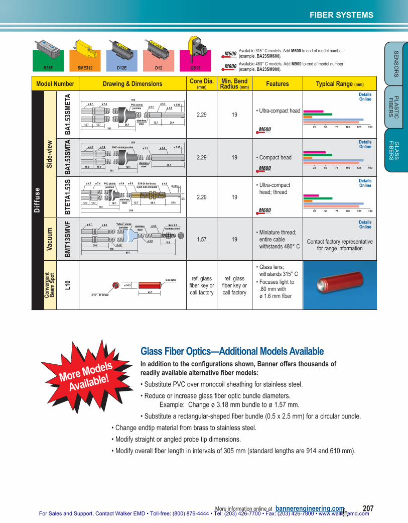
M600 M900Available315°Cmodels.AddM600toendofmodelnumber(example,BA23SM600).
M600 M900 Available480°Cmodels.AddM900toendofmodelnumber(example,BA23SM900).
ModelNumber Drawing & Dimensions Core Dia.
(mm)Min. Bend Radius (mm) Features Typical Range (mm)
Dif
fuse
Stan
dard
BA
23S PVC shrink junction
38.1191
914
12.7 27.9
R 12.7ø 4.820.3
ø 6.4
stainlesssteel
ø 7.4ø 4.7
12.712.7
3.18 19•90°Angle
50 100 150 200
BAT
23S
ø 6.4
stainlesssteel
914
5/16-24UNF brass
2 brass jamnuts included
20.3ø 4.8
12.7 27.9
R 12.7
38.1
ø 7.4
ø 7.4ø 4.7
38.112.712.7
191
PVC shrink junction
3.18 19 •90°Angle/Thread
50 100 150 200
BF2
3P
ø 5.8
PVC withmonocoil
PVC shrink junctionø 7.4ø 4.7
38.112.712.7191
914
ø 7.4ø 4.8
12.712.7
ø 3.18
3.18 19 •Smoothferrule
50 100 150 200
BM
T.44
2P ø 3.0
PVC withmonocoil
610
PVC shrink junction
38.1
19112.7 16.5
ø 4.7ø 7.4ø 3.8
#8-32 thd brass2 jam nuts included
12.712.7 0.69 9.5 •Miniaturethread
2 84 6 10
NA
BT2
3S
ø 8.0ø 6.4
stainlesssteel
5/16-24 thd brass2 jam nuts included
38.112.7
914
ø 3.18PVC shrink
junctionø 7.4ø 4.7
38.112.712.7
191
3.18 19•Thread
50 100 150 200
BTA
23S
R 9.7ø 8.0
ø 6.4
stainlesssteel 5/16-24 thd brass
2 jam nuts included
38.1 15.8
27.9
12.7
914
ø 4.8
PVC shrinkjunction
ø 7.4ø 4.7
38.112.712.7
191
3.18 19 •Thread/90°Angle
50 100 150 200
Min
iatu
re P
robe B
AM
.752
S ø 8.0ø 1.5ø 6.4
stainlesssteel
25.435.6
610
R 3.05
4.8
ø 7.4ø 4.7
38.112.712.7
191
PVC shrinkjunction
1.17 19
•ø1.5mm non-bendableprobe; 90°angle
10 4020 30 50
NA
BM
.752
S ø 7.4
stainlesssteel
25.412.7 12.7
610
ø 7.4ø 4.7
38.112.712.7
191
ø 4.6 ø 1.5PVC shrink junction ø 6.4
1.17 19•ø1.5mm non-bendableprobe
10 4020 30 50
NA
BM
P.75
3P ø 1.5PVC with monocoil
914
25.412.7
PVC shrinkjunction
38.1
19112.7 16.5
ø 3.0 ø 3.8
ø 4.7ø 7.4
1.17 9.5•ø1.5mm non-bendableprobe
10 4020 30 50
NA
Are
a Se
nsin
g (A
rray
)
BR
2.53
S ø 6.4
stainlesssteel
PVC shrink junctionø 4.7 ø 7.4
38.112.712.7191
914
25.4
12.750.8
2x 4.8
6.4 38.10.25
38.1
9.4
3.96 19
•Straightexit; 38mmwidth
50 200100 150 250
BR
23S ø 6.4
stainlesssteel
PVC shrink junctionø 7.4ø 4.7
38.112.712.7191
914
2.54
19.1
11.7
2x 3.2 0.8
6.3
19.1 9.7 3.18 19•Straightexit; 10mmwidth
50 100 150 200
M600 M900
M600 M900
M600 M900
M600 M900
M600 M900
M600 M900
M600 M900
M600 M900
M600 M900
DetailsOnline
DetailsOnline
DetailsOnline
DetailsOnline
DetailsOnline
DetailsOnline
DetailsOnline
DetailsOnline
DetailsOnline
DetailsOnline
DetailsOnline
NA:WORLD-BEAMQS18notrecommended.
For Sales and Support, Contact Walker EMD • Toll-free: (800) 876-4444 • Tel: (203) 426-7700 • Fax: (203) 426-7800 • www.walkeremd.comMore information online at bannerengineering.com 207
PLA
STIC
FIB
ER
SFIBER SYSTEMS
SE
NS
OR
SG
LAS
SFIB
ER
S
Model Number Drawing & Dimensions Core Dia. (mm)
Min. Bend Radius (mm) Features Typical Range (mm)
Dif
fuse
Side
-vie
w
BA
1.53
SMET
A
914
25.4
ø 5.3ø 5.1 ø 4.8
ø 3.05
stainlesssteel 12.7
PVC shrinkjunction
ø 7.4ø 4.7
38.112.712.7191
2.29 19•Ultra-compacthead
25 12550 75 100 150
BA1.
53SM
TA 914
35.1
ø 5.3 ø 6.4 ø 3.05
stainlesssteel
PVC shrink junctionø 7.4ø 4.7
38.112.712.7191
2.29 19 •Compacthead
25 12550 75 100 150
BTE
TA1.
53S
ø 2.29(0.09)
ø 8.0ø 6.4
stainlesssteel
5/16-24 thd brass2 jam nuts included
38.112.7
914
25.4
ø 4.8ø 3.05
5.3
PVC shrinkjunction
ø 7.4ø 4.7
38.112.712.7191
2.29 19
•Ultra-compacthead;thread
25 12550 75 100 150
Vacu
um
BM
T13S
MVF stainless
steelø 4.2 M4 x 0.7
stainless steel
15.0
150914
ø 3.0
ø 3.0
†Teflon
® shrink
junction
29.0
ø 4.0ø 4.7
1.57 19•Miniaturethread; entirecablewithstands480°C
Contactfactoryrepresentativeforrangeinformation
Conv
erge
ntBe
am S
pot
L10
45.7
ø 14.3
5/16" - 24 thread
lens optic ref.glassfiberkeyorcallfactory
ref.glassfiberkeyorcallfactory
•Glasslens;withstands315°C
•Focuseslightto.80mmwith ø1.6mmfiber
R55F SME312 D12E D12
SETUPDO
LO
OFFDelay
Switch Point +DYNAMIC
–STATIC
QS18
Glass Fiber Optics—Additional Models AvailableIn addition to the configurations shown, Banner offers thousands of readily available alternative fiber models:
•SubstitutePVCovermonocoilsheathingforstainlesssteel.
•Reduceorincreaseglassfiberopticbundlediameters. Example:Changeø3.18mmbundletoø1.57mm.
•Substitutearectangular-shapedfiberbundle(0.5x2.5mm)foracircularbundle.
•Changeendtipmaterialfrombrasstostainlesssteel.
•Modifystraightorangledprobetipdimensions.
•Modifyoverallfiberlengthinintervalsof305mm(standardlengthsare914and610mm).
More Models
Available!
M600 M900
M600 M900
M600 M900
DetailsOnline
DetailsOnline
M600 M900Available315°Cmodels.AddM600toendofmodelnumber(example,BA23SM600).
M600 M900 Available480°Cmodels.AddM900toendofmodelnumber(example,BA23SM900).
DetailsOnline
DetailsOnline

For Sales and Support, Contact Walker EMD • Toll-free: (800) 876-4444 • Tel: (203) 426-7700 • Fax: (203) 426-7800 • www.walkeremd.com208 More information online at bannerengineering.com
FIBER SYSTEMSP
LAS
TIC
FI
BE
RS
SE
NS
OR
SG
LAS
S
FIB
ER
S
R55F SME312 D12E D12
SETUPDO
LO
OFFDelay
Switch Point +DYNAMIC
–STATIC
QS18
ModelNumber Drawing & Dimensions Core Dia.
(mm)Min. Bend Radius (mm) Features Typical Range (mm)
Op
po
sed
Stan
dard
IA23
S
914
12.7 27.9
R 12.7ø 4.8720.3
ø 6.4
stainlesssteel
ø 7.4ø 4.7
12.712.7
3.18 19•90°Angle
200 1000400 600 800 1200
IAT2
3S
ø 6.4
stainlesssteel
ø 7.4ø 4.7
12.712.7
914
5/16-24 UNF brass2 brass jam nuts
included
20.3ø 4.8
12.7 27.9
R 12.7
38.1
ø 7.4
3.18 19 •90°Angle/Thread
200 1000400 600 800 1200
IF23
P
ø 5.8PVC withmonocoil
ø 4.7ø 7.4 ø 4.8
ø 7.4
12.712.7
914
12.712.7
3.18 19•Smoothferrule
200 1000400 600 800 1200
IMT.
442P
ø 3.0PVC withmonocoil
914
12.7 16.5
ø 4.7ø 7.4
ø 3.8 #8-32 thd brass2 jam nuts included
12.712.7
0.69 9.5 •Miniaturethread
20 10040 60 80 120
NA
IT23
S
ø 8.0ø 6.4
stainlesssteel
ø 7.4ø 4.75/16-24 thd brass
2 jam nuts included
38.112.712.712.7
914
ø 3.18
3.18 19•Thread
200 1000400 600 800 1200
ITA
23S
ø 8.0
ø 6.4
stainless steel
5/16-24 thd brass2 jam nuts included
38.1 15.812.7
914
ø 7.4
12.712.727.9
ø 4.8
R 9.73.18 19 •Thread/90°Angle
200 1000400 600 800 1200
Min
iatu
re P
robe
IAM
.752
S
ø 8.0ø 1.5ø 6.4
stainlesssteel
ø 7.4ø 4.7
25.435.612.712.7
610
R 3.05
4.8
1.17 19
•ø1.5mm non-bendableprobe; 90°angle
50 100 150 200
IM.7
52S
ø 7.4 ø 1.5ø 4.6ø 6.4
stainlesssteel
ø 7.4ø 4.7
12.7 12.7 25.412.712.7
610
1.17 19•ø1.5mmnon-bendableprobe
50 100 150 200
NA
IMP.
753P
ø 3.0
PVC withmonocoil
914
12.7 16.5
ø 4.7ø 7.4ø 3.8 ø 1.5
25.412.71.17 9.5
•ø1.5mmnon-bendableprobe
50 100 150 200
NA
Are
a Se
nsin
g (A
rray
)
IR2.
53S
12.712.7
ø 6.4
stainlesssteel
ø 7.4ø 4.7
914
6.438.1
25.4
12.7
0.25
38.150.8
9.4
2x 4.8
3.96 19
•Straightexit; 38mmwidth
200 1000400 600 800 1200
IR23
S
ø 6.4
stainlesssteel
12.712.7
914
2.54
19.1
11.7
2x 3.2
0.8
6.3
19.1 9.7
ø 7.4ø 4.7
3.18 19
•Straightexit; 10mmwidth
200 1000400 600 800 1200
M600 M900
M600 M900
M600 M900
M600 M900
M600 M900
M600 M900
M600 M900
M600 M900
M600 M900
Indicateslensesavailableformodel.Seepage209fordetails.
M600 M900Available315°Cmodels.AddM600toendofmodelnumber(example,BA23SM600).
M600 M900 Available480°Cmodels.AddM900toendofmodelnumber(example,BA23SM900).
NA:WORLD-BEAMQS18notrecommended.
DetailsOnline
DetailsOnline
DetailsOnline
DetailsOnline
DetailsOnline
DetailsOnline
DetailsOnline
DetailsOnline
DetailsOnline
DetailsOnline
DetailsOnline

For Sales and Support, Contact Walker EMD • Toll-free: (800) 876-4444 • Tel: (203) 426-7700 • Fax: (203) 426-7800 • www.walkeremd.comMore information online at bannerengineering.com 209
PLA
STIC
FIB
ER
SFIBER SYSTEMS
SE
NS
OR
SG
LAS
SFIB
ER
S
R55F SME312 D12E D12
SETUPDO
LO
OFFDelay
Switch Point +DYNAMIC
–STATIC
QS18
Model Number Drawing & Dimensions Core Dia. (mm)
Min. Bend Radius (mm) Features Typical Range (mm)
Dif
fuse
Side
-vie
w
IA1.
53SM
ETA
914
25.4
ø 5.3ø 5.1 ø 4.8ø 3.05
5.3
stainlesssteel
12.7
ø 7.4
12.712.7
2.29 19•Ultra-compacthead
100 500200 300 400 600
IA1.
53SM
TA
914
35.1
ø 6.4stainless steelø 5.3 ø 3.05
7.12.29 19
•Compacthead
100 500200 300 400 600
ITET
A1.
53S ø 8.0ø 6.4
stainlesssteel
5/16-24 thd brass2 jam nuts included
38.112.7
914
25.4
ø 4.8ø 3.05
5.3
ø 7.4ø 4.7
12.712.7 2.29 19•Ultra-compacthead;thread
100 500200 300 400 600
Vacu
um
IMT7
53SM
VF
29.0
914
12.010.0 3.0
M4 x 0.7stainless steel
M2.5x 0.045ø 4.0ø 4.7
ø 3.0 stainlesssteel
ø 4.2
1.27 19•Miniaturethread;entirecablewithstands480° C
Contactfactoryrepresentativeforrangeinformation
Exte
nded
Ran
ge L
ens
L9Detailed
DimensionsOnline
45.7
ø 14.3
5/16" - 24 thread
lens optic
ref.modelIT23S
ref.modelIT23S
•Glasslens;withstands315° C
L16F
Detailed
DimensionsOnline
58.4
ø 28.6
5/16" - 24 thread
lens optic
ref.modelIT23S
ref.modelIT23S
•Plastichousing;withstands105° C
L16F
AL
Detailed
DimensionsOnline
58.4
ø 28.6
5/16" - 24 thread
lens optic
ref.modelIT23S
ref.modelIT23S
•Aluminumhousing;withstands315° C
L16F
SSDetailed
DimensionsOnline
58.4
ø 28.6
5/16" - 24 thread
lens optic
ref.modelIT23S
19•Stainlesssteelhousingwithstands480° C
Vacu
um F
eed
Thro
ugh
VFT-
M8M
VSDetailed
DimensionsOnline
10.0 35.0
4.04.0
12.7
40.0
22.23
ø 3.56 imageconduit
9.53 4.75
#4-40SS set screw
stainless steelelectropolish finish
#4-40SS set screw
M8 x 1.25
4.75
Viton O-ringA — - — A CROSS-SECTION DETAIL
A A
3.56 –•Sealsto1x10-9torr; withstands120° C
Liqu
id L
evel
TGR
Detailed
DimensionsOnline
ø 9.7
ø 3.18 (±0.125)
glass rod
5/16-24 brassinternal thread
12.7
97.8effective length
90°
3.18 –
•UsewithBT23S•Sensorswitches whentipofglass rodisimmersedin liquid
M600 M900
M600 M900
M600 M900
M600 M900Available315°Cmodels.AddM600toendofmodelnumber(example,BA23SM600).
M600 M900 Available480°Cmodels.AddM900toendofmodelnumber(example,BA23SM900).
DetailsOnline
DetailsOnline
DetailsOnline

For Sales and Support, Contact Walker EMD • Toll-free: (800) 876-4444 • Tel: (203) 426-7700 • Fax: (203) 426-7800 • www.walkeremd.com210 More information online at bannerengineering.com
SPECIAL PURPOSES
LOT
& L
AB
EL
CO
LOR
&
LUM
INES
CEN
CE
OP
TIC
AL
BU
TTO
NS
MAG
NE
TIC
PAR
T &
AR
EA