Manually Lever Operated Hoist and Hoist Maintenancetulsacranewerx.com/Data/Lever Operated Hoist...
57
Manually Lever Operated Hoist Inspection and Hoist Maintenance Personnel Manual HOIST MANUFACTURERS INSTITUTE 8720 Red Oak Blvd., Suite 201 Charlotte, NC 28217-3992 Prepared and Published by SM © 2003 Hoist Manufacturers Institute All Rights Reserved
Transcript of Manually Lever Operated Hoist and Hoist Maintenancetulsacranewerx.com/Data/Lever Operated Hoist...
ManuallyLeverOperatedHoistInspectionand HoistMaintenancePersonnelManual
HOIST MANUFACTURERS INSTITUTE
8720 Red Oak Blvd., Suite 201Charlotte, NC 28217-3992
Prepared and Published by
SM
© 2003 Hoist Manufacturers Institute All Rights Reserved

TABLE OF CONTENTS
INTRODUCTION AND DISCLAIMER 3
MANUALLY LEVER OPERATED HOIST TYPES 9TENSIONING MEDIUM TYPES 9MANUALLY LEVER OPERATED OPERATION TYPES 10
INSPECTION PROCEDURES AND MAINTENANCE 13
MANUALLY LEVER OPERATED HOIST INSPECTION AND MAINTENANCE PERSONNEL RESPONSIBILITIES AND REQUIREMENTS 15
DAILY OR PRESTART HOIST INSPECTIONS 16
FREQUENT AND PERIODIC HOIST INSPECTIONS 18
HOIST INSPECTION REPORTS 26
HOOK INSPECTION 27
WIRE ROPE INSPECTION 30
LOAD CHAIN INSPECTION 36
WEB STRAP INSPECTION 41
LOAD CONTROLLING MECHANISM – HOIST BRAKINGSYSTEM / RATCHET AND PAWL INSPECTION 42
HOIST TESTINGAPPENDIX A:
DEFINITIONS OF VARIOUS HOIST TERMS 44
APPENDIX B:HOIST REFERENCE DOCUMENTS AND STANDARDS 47
APPENDIX C:HOIST INSPECTION REPORT FORMS (L1 THROUGH L6) 48
1

INTRODUCTION AND DISCLAIMER
The Hoist Manufacturers Institute (HMI) is an independent incorporated trade association affiliatedwith the Material Handling Industry of America Division of Material Handling Industry (MHI).
MHI provides HMI with certain services and, in connection with this Manually Lever Operated HoistInspection and Hoist Maintenance Personnel Manual, arranges for its production and distribution.Neither MHI, its officers, directors, employees nor members have any other participation in the devel-opment and preparation of the information contained in this Manual.
All inquiries concerning this Manually Lever Operated Hoist Inspection and Hoist MaintenancePersonnel Manual should be directed in writing to the Chairman of the HMI Engineering Committee,c/o Hoist Manufacturers Institute, 8720 Red Oak Boulevard, Suite 201, Charlotte, North Carolina,28217-3992.
This Manual has been prepared by HMI and its Engineering Committee with the sole intent of offeringinformation and suggestions to parties engaged with Manually Lever Operated Hoist Inspection andMaintenance Personnel in their inspection and maintenance of manually lever operated hoists. ThisManual is advisory only and should be regarded as a guide that the user may or may not choose toadopt, modify or reject. The information does not constitute a comprehensive safety program andshould not be relied upon as such. Such a program should be developed and an independent safetyadviser consulted to do so. At times, hoist inspection and maintenance personnel may be required tooperate a manually lever operated hoist in the performance of their inspection and maintenance duties.Operation of a manually lever operated hoist involves more than operating the controls of the hoist. Theoperator must consider and anticipate the motions, actions, and loads that will occur as a result of oper-ating the hoist. Therefore, it is important for the Manually Lever Operated Hoist Inspection andMaintenance Personnel to be instructed in the operation of manually lever operated hoists and to under-stand the severe consequences that may result from careless operation. Refer to the Manually LeverOperated Hoist Operators Manual, latest edition, published by HMI.
MANUALLY LEVER OPERATED HOIST INSPECTIONAND MAINTENANCE PERSONNEL MANUAL
MATERIAL HANDLING INDUSTRYAND ITS MATERIAL HANDLING INDUSTRY OF AMERICA DIVISION
3

INTRODUCTION AND DISCLAIMER
The acceptance or use of this Manual is completely voluntary. Its existence does not preclude anyonefrom using information not conforming to it. It is not intended that the recommendations in this Manualtake precedence over existing plant safety rules and regulations, OSHA regulations, or instructionsissued by the manufacturer of the manually lever operated hoist. However, a thorough study of the fol-lowing information should provide a better understanding of safe operation and afford a greater marginof safety for people and machinery on the plant floor.
It must be recognized that this is a Manual of recommendations for the Manually Lever Operated HoistInspection and Maintenance Personnel and its use is permissive not mandatory. It is the responsibilityof the owner of the hoist to make personnel aware of all federal, state and local rules, codes and plantsafety rules and regulations and instructions and to make certain operators and inspection and mainte-nance personnel are properly trained.
DISCLAIMER OF LIABILITY: MHI, HMI AND THEIR SUCCESSORS, ASSIGNS, OFFICERS,AGENTS, EMPLOYEES AND THEIR MEMBERS ASSUME NO RESPONSIBILITY AND DIS-CLAIM ALL LIABILITY OF ANY KIND, HOWEVER ARISING, AS A RESULT OF ACCEP-TANCE OR USE OR ALLEGED USE OF THIS MANUAL. USER SPECIFICALLY UNDER-STANDS AND AGREES THAT MHI AND HMI AND THEIR SUCCESSORS, ASSIGNS, OFFI-CERS, AGENTS, EMPLOYEES AND MEMBERS SHALL NOT BE LIABLE UNDER ANY LEGALTHEORY OF ANY KIND FOR ANY ACTION OR FAILURE TO ACT WITH RESPECT TO THERECOMMENDED OPERATIONS OR ANY OTHER THING COVERED BY THIS MANUAL.
DISCLAIMER OF WARRANTY: MHI, HMI MAKE NO WARRANTIES OF ANY KIND,EXPRESS, IMPLIED, OR STATUTORY, IN CONNECTION WITH THE INFORMATION IN THISMANUAL. MHI AND HMI SPECIFICALLY DISCLAIM ALL IMPLIED WARRANTIES OF MER-CHANTABILITY OR OF FITNESS FOR PARTICULAR PURPOSE.
DISCLAIMERS AND INDEMNITY
4

INTRODUCTION AND DISCLAIMER
INDEMNITY: BY REFERRING TO OR OTHERWISE EMPLOYING THIS MANUAL, THE USERAGREES TO DEFEND, PROTECT, INDEMNIFY, AND HOLD MHI AND HMI AND THEIR OFFI-CERS, AGENTS, EMPLOYEES AND MEMBERS HARMLESS FROM AND AGAINST ALLCLAIMS, LOSSES EXPENSES, DAMAGES, AND LIABILITIES, DIRECT, INCIDENTAL, ORCONSEQUENTIAL, ARISING FROM ACCEPTANCE OR USE OR ALLEGED ACCEPTANCE ORUSE OF THIS MANUAL, INCLUDING LOSS OF PROFITS AND REASONABLE ATTORNEYS’FEES WHICH MAY ARISE OUT OF THE ACCEPTANCE OR USE OR ALLEGED ACCEPTANCEOR USE OF THIS MANUAL. THE INTENT OF THIS PROVISION AND OF THE USER IS TOABSOLVE AND PROTECT MHI AND HMI AND THEIR OFFICERS, AGENTS, EMPLOYEESAND MEMBERS FROM ANY AND ALL LOSS RELATING IN ANY WAY TO THIS MANUAL,INCLUDING THOSE RESULTING FROM THE USER’S OWN NEGLIGENCE.
Taking precedence over any specific rule,however, is the most important rule of all:
“USE COMMON SENSE.”
It is a responsibility of the manually lever operated hoist owner/user to establish programs to:1. train and designate hoist operators, and2. train and designate hoist inspection and maintenance personnel.
The words shall and should are used throughout this Manual in accordance with definitions in theASME B30 standards as follows:
shall this word indicates that a rule is mandatory and must be followed.
should this word indicates that a rule is a recommendation, the advisability of which dependson the facts in each situation.
5

INTRODUCTION AND DISCLAIMER
Manually Lever Operated Hoist Operator and Inspection and Maintenance Personnel training programsshould be based on requirements in accordance with the latest edition of:
• ASME B30.21 Safety Standard for Manually Lever Operated Hoists
Such training programs should also provide information for compliance with any Federal, State, orLocal Code requirements, existing plant safety rules and regulations, and the instructions furnished bythe manufacturer of the hoist.
If a manually lever operated hoist is installed as part of an overhead crane or monorail system, refer-ence should also be made to the latest edition for the following HMI publications:
• Hoist Operators Manual• Hoist Inspection and Hoist Maintenance Personnel Manual
IT IS A RESPONSIBILITY OF THE OWNER/USER TO INSTALL, INSPECT, TEST, MAIN-TAIN, AND OPERATE A MANUALLY LEVER OPERATED HOIST IN ACCORDANCE WITHTHE ASME B30.21 SAFETY STANDARD AND OSHA REGULATIONS. IF THE HOIST ISINSTALLED AS PART OF A TOTAL LIFTING SYSTEM, IT IS ALSO THE RESPONSIBILITYOF THE OWNER/USER TO COMPLY WITH THE APPLICABLE ASME B30 VOLUME THATADDRESSES OTHER TYPES OF EQUIPMENT USED IN THE SYSTEM.
FURTHER, IT IS THE RESPONSIBILITY OF THE OWNER/USER TO REQUIRE THAT ALLPERSONNEL THAT WILL INSTALL, INSPECT, TEST, MAINTAIN, AND OPERATE A MAN-UALLY LEVER OPERATED HOIST READ THE CONTENTS OF THE INSTRUCTION MAN-UAL FURNISHED BY THE MANUFACTURER OF THE HOIST, ASME B30.21 SAFETYSTANDARD FOR MANUALLY LEVER OPERATED HOISTS, AND OSHA REGULATIONS. IFTHE HOIST IS INSTALLED AS PART OF A TOTAL LIFTING SYSTEM, THE APPLICABLEASME B30 VOLUME THAT ADDRESSES OTHER TYPES OF EQUIPMENT USED IN THESYSTEM MUST ALSO BE READ BY ALL PERSONNEL.
NOTICE
6
INTRODUCTION AND DISCLAIMER
The Safety Alert Symbol is used in this Manual to indicate hazards and to alert the reader to informa-tion that should be known, understood, and followed in order to avoid DEATH or SERIOUS INJURY.
Read and understand this Manual before using, inspecting,or maintaining the manually lever operated hoist.
Important issues to remember during operation are provided in the hoist control stations at various loca-tions on the hoist and in the manuals by DANGER, WARNING, or CAUTION instructions or plac-ards, that alert personnel to potential hazards, proper operation, load limitations, and more.
DANGER Indicates an imminently hazardous situation which, if not avoided, will result indeath or serious injury.
WARNING Indicates a potentially hazardous situation which, if not avoided, could result indeath or serious injury.
CAUTION Indicates a potentially hazardous situation which, if not avoided, may result inminor or moderate injury. It may also be used to alert against unsafe practices.
SAFETY ALERT SYMBOL
7
INTRODUCTION AND DISCLAIMER
Because the manufacturer of the lever operated hoist has no direct involvement or control over the man-ually lever operated hoist’s operation and application, conforming to good safety practices is theresponsibility of the owner, the user, and its operating personnel.
Only those Authorized and Qualified Personnel who have shown that they have read and have under-stood this Manual and the manufacturer’s manual and that they understand the proper operation andmaintenance of the hoist should be permitted to operate and/or maintain the hoist.
READ and OBEY all Danger, Warning, Caution, and Operating Instructions on the hoist and in allmanufacturers’ manuals and this Manual. Make sure that all placards are in place and legible.
Failure to comply with safety precautions in this Manual, in the manufacturer’s manual and on the hoistmaybe a safety violation that may result in serious injury, death, or property damage.
PLACARDS AND INSTRUCTIONS
BEFORE INSTALLING, REMOVING, INSPECTING, OR PERFORMING ANY MAINTE-NANCE ON A MANUALLY LEVER OPERATED HOIST, MAKE CERTAIN THE LOAD HASBEEN PARKED AND REMOVED FROM THE HOIST. FOLLOW OTHER MAINTENANCEPROCEDURES OUTLINED IN THE MANUAL FURNISHED BY THE MANUFACTURER OFTHE HOIST AND ASME B30.21.
FAILURE TO READ AND COMPLY WITH ANY ONE OF THE LIMITATIONS NOTED INTHIS MANUAL AND THE INSTRUCTION MANUAL FURNISHED BY THE MANUFAC-TURER OF THE HOIST CAN RESULT IN SERIOUS BODILY INJURY OR DEATH, AND/ORPROPERTY DAMAGE.
8

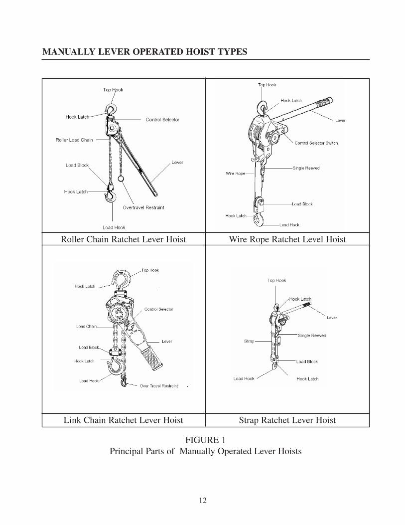
MANUALLY LEVER OPERATED HOIST TYPES
Manually lever operated hoists are defined in ASME B30.21 as a lever operated manual device used tolift, lower, or pull a load and to apply or release tension. Lever operated hoists are a basic and versatilepiece of equipment used in manufacturing, warehousing, construction, and numerous other applicationsto aid workers in the handling, moving, and tensioning of loads.
Manually lever operated hoists are generally available in three types as defined by the medium used totension or move the load. The three types are chain, wire rope, and web strap. All three types share incommon the features of a hook at the hoist frame, a hook at the load block and a lever to apply a loadbetween the two hoist hooks. These three types may use ratchet and pawl or friction brake operatingmechanisms and are illustrated in Figure 1 on page 12.
Chain type — uses welded link load chain or roller chain as a tensioning medium
Wire rope type — uses wire rope (cable) as a tensioning medium
Web strap type — uses a web strap of nylon, polyester, or similar synthetic material as a tensioning medium
• Welded Link Load Chain• Roller Load Chain• Wire Rope• Web Strap
WELDED LINK LOAD CHAIN
Welded link load chain consists of a series of interwoven formed and welded links. The links fit pock-ets of the hoist load sprocket that transmits motion to the load chain. The load sprocket may also becalled load wheel, load sheave, pocket wheel, chain wheel, or lift wheel. Welded link load chain sizesare stated as the diameter of the wire used to form the link, i.e. 1/4 in., 5/16 in., etc. Welded link loadchain is designed and manufactured to specific dimension and material strength requirements for a spe-cific hoist. Welded link load chain is not interchangeable between different manufacturers’ hoists; andis not interchangeable with welded link lifting chain used for other purposes such as chain slings andload securement. Only welded link load chain with specifications as originally stated by the hoist man-ufacturer should be used on any welded link load chain hoist.
LEVER OPERATED HOIST TENSIONING MEDIUM TYPES
9

MANUALLY LEVER OPERATED HOIST TYPES
ROLLER LOAD CHAIN
Roller load chain consists of a series of alternately assembled roller links and pin links where the pinsarticulate inside bushings and the rollers are free to turn on the bushings. Pins and bushings are pressfit in their respective link plates. The links fit teeth of the hoist load sprocket that transmits motion tothe load chain. The load sprocket may also be called load wheel, load sheave, chain wheel, or lift wheel.Roller load chain sizes are stated as the pitch or spacing between pins, i.e. 5/8 in., 3/4 in., etc. Rollerload chain for use on hoists is designed and manufactured to specific material strength requirements forhoist applications. Roller load chain for hoist applications has different manufacturing specificationsthan roller chain for power transmission applications. Therefore, hoist roller load chain is not inter-changeable with power transmission roller chain. Only roller load chain with specifications as origi-nally stated by the hoist manufacturer should be used on any roller load chain hoist.
WIRE ROPE
Wire rope consists of a core, strands, and wires that comprise a strand. The wire rope fits and wrapsonto grooves on the circumference of the hoist drum that transmits motion to the wire rope. Wire ropesizes are stated as the diameter of a circle that would enclose the wire rope strands, i.e. 5/16 in., 3/8 in.,etc. Each wire rope size is available in various rope constructions and materials. The construction andmaterial strength requirements of the wire rope are selected by the hoist manufacturer in accordancewith the design specification requirements of the hoist. Therefore, only wire rope with specifications asoriginally stated by the hoist manufacturer should be used on any wire rope hoist.
WEB STRAP
Web strap consists of nylon or polyester (or other synthetic) woven material. The web strap fits andwraps onto the circumference of the drum that transmits motion to the web strap. Web strap sizes arestated as the material width. Each web strap size is available in various constructions and materials. Theconstruction and material strength requirements of the web strap are selected by the hoist manufactur-er in accordance with the design specification requirements of the hoist. Therefore, only web strap withspecifications as originally stated by the hoist manufacturer should be used on any web strap hoist.
10

MANUALLY LEVER OPERATED HOIST TYPES
As previously stated, operation defines the type of mechanism used to apply the load. Operation typesinclude:
• Ratchet and pawl operation• Friction brake operation
Ratchet and pawl type manually lever operated hoists operate using a ratchet which is driven by thelever. The ratchet is integral or attached to a pocket wheel for chain type hoists or a drum for wire ropeand web strap type. The ratchet is typically controlled by a driving pawl and a holding pawl. The driv-ing pawl is driven by the lever and imparts motion to the ratchet which tensions or releases the loadwith the load alternately coming to rest on the holding pawl when the lever is released by the operator.A directional lever or switch permits the operator to select tension or release (directions). Successiverepeated operation of the lever serves to either apply more tension or release tension until the load ten-sion is zero.
Friction brake type manually lever operated hoists operate by using a brake mechanism which may bedirectly connected or connected via a gear train to a pocket wheel for chain type hoists or a drum forwire rope and web strap type. The lever drives the locked brake over a one way ratchet mechanism thusimparting tension to the chain wire rope or web strap. To release tension, the lever driving direction isreversed and the lever force applied to open the brake which allows the load to release in a controlledmanner. When the lever force is released the brake automatically closes in response to the load.Successive repeated operation of the lever serves to either apply more tension or release tension untilthe load tension is zero.
LEVER OPERATED HOIST OPERATION TYPES
11
MANUALLY LEVER OPERATED HOIST TYPES
12
Roller Chain Ratchet Lever Hoist Wire Rope Ratchet Level Hoist
Link Chain Ratchet Lever Hoist Strap Ratchet Lever Hoist
FIGURE 1Principal Parts of Manually Operated Lever Hoists
Lever
Lever

MANUALLY LEVER OPERATED HOIST INSPECTION ANDMAINTENANCE PROCEDURES
Manually lever operated hoist inspection, maintenance, and repair can be performed in various waysdepending on the conditions, policies, and practices of a particular owner/user. Maintenance policiesand practices are determined by the size of the operation and number of employees, the availability oftrained and experienced in-house maintenance persons, and the type of hoists.
Regardless of the manner used to perform manually lever operated hoist inspections, maintenance, andrepairs, each function should be performed only by trained, experienced, and qualified hoist inspection,maintenance, and repair personnel. For information on hoist inspection, maintenance, and repair,always refer to the manual furnished by the manufacturer of the hoist.
Manually lever operated hoists shall be maintained, inspected, and tested in accordance with the man-ual furnished by the manufacturer of the hoist and in accordance with the intervals and requirements ofASME B30.21.
Before maintenance or inspections are performed on a manually lever operated hoist, precautions shallbe taken, which include those listed and recommended below. While the hoist operator should not per-form inspection, maintenance, or repair on a hoist, unless trained, qualified, and authorized to do so,the operator may be involved in performing these precautions before maintenance or inspections areperformed by others.
MAINTENANCE AND INSPECTION PROCEDURES
THE HOIST OPERATOR SHOULD NOT PERFORM FREQUENT AND PERIODIC INSPEC-TIONS, MAINTENANCE, OR REPAIR ON A MANUALLY LEVER OPERATED HOIST,UNLESS THE OPERATOR HAS BEEN TRAINED TO PERFORM SUCH INSPECTIONS,MAINTENANCE, OR REPAIR ON A MANUALLY LEVER OPERATED HOIST AND IS DES-IGNATED BY THE HOIST OWNER/USER TO PERFORM SUCH INSPECTIONS, MAINTE-NANCE, AND REPAIR.
NOTICE
13

1. If a load is attached to the manually lever operated hoist, it should be landed. On all manuallylever operated hoists, the load block should be lowered onto a surface that allows the liftingmedium to be slackened.
2. If the hoist is suspended from a fixed location, maintenance and inspections can be performedin place, or the hoist can be removed to a repair area as required.
3. If maintenance or inspection is carried out while the hoist is suspended from a fixed location,warning signs and barriers should be utilized on the floor beneath the hoist, if work creates ahazardous area on the floor beneath the hoist.
4. Safe access to the manually lever operated hoist, such as scaffolding, work platforms, etc.,should be provided, as necessary, for personnel that will perform maintenance, repair, or inspec-tion. If personnel are required to work above floor or ground level, a fall prevention policy andprocedure shall be developed, documented, and implemented by the owner/user.
5. After maintenance, repair, or inspection work is completed, and before the hoist is returned tonormal operation:
• Any guards and covers on the hoist that were removed to perform maintenance, repair, orinspection work shall be reinstalled.
• Any safety devices on the hoist or surrounding area that were deactivated to perform main-tenance, repair, or inspection work shall be reactivated.
• Any parts that were replaced and other loose material shall be removed.• All equipment used in the maintenance, repair, or inspection work shall be removed.
6. Warning signs, barriers, and guards shall be removed only by authorized personnel.
7. If the extent of the maintenance or repair work requires any testing as outlined in ASME B30.21or any other applicable ASME B30 volume; such tests shall be conducted before the manuallylever operated hoist is returned to normal operation.
MAINTENANCE AND INSPECTION PROCEDURES
14

IT IS RECOMMENDED THAT MANUALLY LEVER OPERATED HOISTINSPECTION AND MAINTENANCE PERSONNEL SHALL:
Be required to read the operation, inspection, and maintenance sections of the manual furnished withthe hoist.
Be required to read the warnings in the manual furnished with the hoist.
Be required to read the instructions and warning labels on the hoist.
Be required to read the operation, inspection, and maintenance sections of ASME B30.21.
Be required to be familiar with the hoist controls before being authorized to operate the hoist.
Have normal depth perception, field of vision, reaction time, manual dexterity, and coordination for thework to be performed.
NOT be subject to seizures, loss of physical control, physical defects, or emotional instability thatcould result in actions of the operator being a hazard to the operator or others.
NOT operate a hoist when under the influence of alcohol or drugs.
NOT operate a hoist when under the influence of medication that could result in actions of the opera-tor being a hazard to the operator or others.
DO NOT LIFT PERSONNEL.DO NOT LIFT LOADS OVER PEOPLE.
MANUALLY LEVER OPERATED HOISTS ARE INTENDED ONLY FOR MOVING OR TEN-SIONING OF FREE UNGUIDED LOADS. DO NOT USE A HOIST TO MOVE OR TENSIONLOADS THAT ARE NOT LIFTED VERTICALLY, LOADS THAT ARE NOT FREE OR THATARE GUIDED. IF SUCH CONDITIONS EXIST, THE OPERATOR SHOULD CONTACT THESUPERVISOR FOR INSTRUCTIONS.
NOTICE
MANUALLY LEVER OPERATED HOIST INSPECTION ANDMAINTENANCE PERSONNEL RESPONSIBILITIESAND REQUIREMENTS
15

MANUALLY LEVER OPERATED HOIST INSPECTIONS
In accordance with the requirements of ASME B30.21 the hoist operator should perform daily (prestart)inspections at the start of each shift, or at the time the hoist is first used during each shift. The dailyinspection is a visual and audible examination of the hoist. Records of the daily inspection are notrequired except as required by the hoist owner/user. Daily inspection items that should be performedby the operator at the start of each shift, or at the time the hoist is first used during each shift, includethe following outlined in Table 1.
INSPECTION ITEM DESCRIPTION OF INSPECTION CHECK POINTS
Tagged Hoist Check that hoist is not tagged with an out-of-order sign.All Functional Mechanisms Check for proper operation and adjustment.Controls Check that all direction motions agree with directional selection setting
when lever is actuated. Hook Check for damage, cracks, nicks, gouges, deformation of the throat open-
ing, wear on the saddle or load bearing point, and twist.Hook Latch Check that hook latch, if provided, is not missing and that it operates
properly.Operating Lever Check for bends, cracks, and other damage.Tensioning Medium – Chain Check for nicks, gouges, and any type of deformation or damage to the
chain. Check for proper lubrication of load chain.Wire Rope Check for distortion, kinking, crushing, unstranding, birdcaging, main
strand displacement and core protrusion; general corrosion; broken andcut strands; number, distributions and type of visible broken wires (12randomly distributed broken wires in one lay or four broken wires in onestrand and one outer wire broken at the contact point with the core which-has worked its way out and protrudes or loops out is cause for removalfrom service).
TABLE 1MANUALLY LEVER OPERATED HOISTS
DAILY INSPECTION(REFER ALSO TO THE MANUAL FURNISHED BY THE HOIST MANUFACTURER)
DAILY OR PRESTART HOIST INSPECTIONS
16

MANUALLY LEVER OPERATED HOIST INSPECTIONS
INSPECTION ITEM DESCRIPTION OF INSPECTION CHECK POINTS
Web Strap Check for gross damage from melting and charring; acid or caustic burns;weld spatter; broken stitching; cuts or tears; damaged eyes or fittings;abrasive wear; and knots.
Reeving Check that tensioning medium is properly reeved and that it is not kinkedor twisted, and that parts are not twisted about each other.
Brakes (if equipped) Check that hoist motion does not have excessive drift and that stoppingdistance is normal.
Ratchet and Pawl Check for proper operation of springs and pawls. Make sure (if equipped) pawls operate freely and that load is controlled during operation.Oil or Grease Leakage Check for any sign of oil or grease leakage on the hoist.Unusual Sounds Check for any unusual sounds from the hoist and hoist mechanism while
operating the hoist.Warning and Safety Labels Check that warning and other safety labels are not missing and that they
are legible.
IF ANY DAMAGE OR MALFUNCTIONS ARE NOTED BY THE DAILY INSPECTION ITEMS,THE OPERATOR SHALL NOT OPERATE THE LEVER HOIST, AND SHALL IMMEDIATELYADVISE THE SUPERVISOR SO CORRECTIVE ACTION CAN BE TAKEN. IF THE HOIST ISTAGGED WITH AN OUT-OF-ORDER SIGN, THE OPERATOR SHALL NOT OPERATE THEHOIST.
LEVER HOIST OPERATORS SHOULD BE AWARE OF MALFUNCTIONS OF THE EQUIP-MENT THAT COULD OCCUR DURING OPERATION, AND SHOULD IMMEDIATELY STOPOPERATION IF SUCH MALFUNCTIONS OCCUR, AND SHOULD IMMEDIATELY ADVISETHE SUPERVISOR SO CORRECTIVE ACTION CAN BE TAKEN.
TABLE 1MANUALLY LEVER OPERATED HOISTS
DAILY INSPECTION (CONTINUED)(REFER ALSO TO THE MANUAL FURNISHED BY THE HOIST MANUFACTURER)
17

MANUALLY LEVER OPERATED HOIST INSPECTIONS
Frequent and periodic inspections of the hoist in accordance with the requirements of the ASMEB30.21 standard and as outlined in the manual furnished by the hoist manufacturer are required.
Frequent and periodic inspections are to be performed by trained, experienced, and qualified hoistinspection and hoist maintenance personnel.
Refer to the FREQUENT AND PERIODIC HOIST INSPECTIONS section of this manual.
THE LEVER HOIST OPERATOR SHALL NOT PERFORM FREQUENT OR PERIODICINSPECTIONS, OR PERFORM MAINTENANCE ON A HOIST UNLESS THE OPERATORHAS BEEN TRAINED TO PERFORM SUCH INSPECTIONS OR MAINTENANCE, AND ISDESIGNATED BY THE HOIST OWNER/USER TO PERFORM SUCH INSPECTIONS ORMAINTENANCE.
NOTICE
FREQUENT AND PERIODIC MANUALLY LEVEROPERATED HOIST INSPECTIONS
18
FREQUENT AND PERIODIC HOIST INSPECTIONS
The inspection procedure for manually lever operated hoists in regular service is divided into two gen-eral classifications as outlined in ASME B30.21. These two general classifications are based upon theintervals at which inspections should be performed. The intervals are also dependent upon the natureof the critical components of the equipment, and the degree of exposure of equipment components andparts to wear and deterioration. The degree of exposure is dependent upon hoist activity, severity ofhoist service, and the environment of hoist location. These two general classifications of inspection aredesignated as frequent and periodic.
FREQUENT INSPECTION: Frequent inspections are visual and audio external inspections andexaminations by the operator or other designated personnel with no records required. Usual or mini-mum inspection intervals are as follows:
Normal service — monthlyHeavy service — weekly to monthlySevere service — daily to weekly
PERIODIC INSPECTION: Periodic inspections are visual, hands-on, and audio external inspectionsand examinations by designated personnel making written records of external conditions to provide thebases for a continuing evaluation of the hoist and components. If the external inspection indicates theneed, disassembly may be required to make a more detailed inspection and examination. Usual or min-imum inspection intervals are as follows:
Normal service — annuallyHeavy service — semiannuallySevere service — quarterly
THE INSPECTION INTERVALS LISTED ABOVE ARE THE USUAL OR MINIMUM RECOM-MENDATIONS AND ARE FOR REFERENCE PURPOSES ONLY. THEY ARE BASED ON SIN-GLE SHIFT OPERATION UNDER NORMAL OPERATING CONDITIONS AND NORMALENVIRONMENTAL CONDITIONS. ACTUAL OPERATING AND ENVIRONMENTAL CONDI-TIONS SHOULD BE REVIEWED BY A QUALIFIED PERSON AND APPROPRIATE INSPEC-TION INTERVALS ESTABLISHED ON THE RECOMMENDATIONS OF THE QUALIFIEDPERSON.
19

FREQUENT AND PERIODIC HOIST INSPECTIONS
Definitions of service taken from ASME B30.21 for manually lever operated hoists.
Normal service involves operation of the equipment with randomly distributed loads within the ratedload limit, or uniform loads less than 65% of rated load, for not more than 15% of the time of a singlework shift for manually-operated equipment and not more than 25% of the time of a single work shiftfor electric-powered equipment.
Heavy service involves operation of the equipment within the rated load limit that exceeds normal serv-ice.
Severe service involves operation of the equipment in normal service or heavy service with abnormaloperating conditions.
The ASME standards state: A manually lever operated hoist that is not in regular service, that has beenidle for a period of one month or more, but less than one year, shall be inspected in accordance withthe requirements for frequent inspection before being placed into or back into service.
The ASME standards state: A manually lever operated hoist that is not in regular service, that has beenidle for a period of one year or more, shall be inspected in accordance with the requirements for peri-odic inspection before being placed into or back into service.
Recommended items to be checked for deficiencies or damage during frequent and periodic inspectionsare outlined in Table 2, pages 21 to 24 for manually lever operated hoists. Also, refer to the manual fur-nished by the manufacturer of the hoist for additional information on frequent and periodic inspections.
Detailed inspection procedures for some items should be found in specific sections of the manual fur-nished by the manufacturer with the equipment. Inspections may be performed with the hoist in its nor-mal location and do not require that the hoist be disassembled. Covers and other items normally sup-plied to allow inspection of components should be opened or removed for these inspections. Any defi-ciencies or damage such as those listed in Table 2, page 21 shall be examined by a designated personto determine whether they constitute a hazard, or whether any disassembly is necessary for a moredetailed inspection. The hoist operator should make observations during regular operation for any defi-ciencies or damage that might appear between inspections.
20

FREQUENT AND PERIODIC HOIST INSPECTIONS
INSPECTION INSPECTION DESCRIPTION OF INSPECTION ITEM FREQUENT PERIODIC CHECK POINTS
All Functional • • Check for proper operation andMechanisms adjustment.
Controls • • Check that all direction motions agree withdirectional selection setting when lever isactuated.
Hooks • • Check for damage, cracks, nicks, gouges,deformation of the throat opening, bendingof the shank on neck, wear on the saddle orload bearing point, and twist.
Hook Latches • • Check that hook latches, if provided, arenot missing and that they operate properly.
Operating Lever • • Check for bends, cracks, and other damage.
Tensioning Medium – Load Chain • • Check while under load in lifting and(Welded Link & Roller) lowering direction – observe chain and
sprockets. Chain should feed smoothly inboth directions. If chain jumps, binds, or isnoisy, clean and lubricate. If problem per-sists, inspect chain and mating parts forwear, distortion, and damage per manufac-turer’s manual.
TABLE 2MANUALLY LEVER OPERATED HOISTS
FREQUENT AND PERIODIC INSPECTIONS(REFER ALSO TO THE MANUAL FURNISHED BY THE HOIST MANUFACTURER)
21

FREQUENT AND PERIODIC HOIST INSPECTIONS
INSPECTION INSPECTION DESCRIPTION OF INSPECTION ITEM FREQUENT PERIODIC CHECK POINTS
Wire Rope • • Check for distortion, kinking, crushing,unstranding, birdcaging, main strand dis-placement, and core protrusion; generalcorrosion; broken and cut strands; num-ber, distributions and type of visible bro-ken wires (12 randomly distributed bro-ken wires in one lay or four broken wiresin one strand and one outer wire broken atthe contact point with the core which hasworked its way out and protrudes or loopsout is cause for removal from service).
Web Strap • • Check for gross damage from melting andcharring; acid or caustic burns; weld spat-ter; broken stitching; cuts or tears; dam-aged eyes or fittings; abrasive wear; andknots.
Reeving • • Check that tensioning medium is properlyreeved and that it is not kinked or twisted,and that parts are not twisted about eachother.
Brakes • • Check that hoist motion does not have(if equipped) excessive drift and that stopping distance
is normal.
TABLE 2MANUALLY LEVER OPERATED HOISTS
FREQUENT AND PERIODIC INSPECTIONS (CONTINUED)(REFER ALSO TO THE MANUAL FURNISHED BY THE HOIST MANUFACTURER)
22

FREQUENT AND PERIODIC HOIST INSPECTIONS
INSPECTION INSPECTION DESCRIPTION OF INSPECTION ITEM FREQUENT PERIODIC CHECK POINTS
Ratchet and Pawl • • Check for proper operation of springs(if equipped) and pawls. Make sure pawls operate
freely and that load is controlled duringoperation.
Oil or Grease Leakage • • Check for any sign of oil or grease leakageon the hoist.
Unusual Sounds • • Check for any unusual sounds from thehoist and hoist mechanism while operatingthe hoist.
Warning and Safety • • Check that warning and other safety Labels labels are not missing and that they are
legible.
Hoist Frame and • • Check for damage that would effectSupport strength such as gouges, cracks, bending,
and distortion.
Fastening Devices • Check for items not properly secured(bolts, nuts, pins, etc.) (tightened), damaged, or missing (torque
bolts per hoist manufacturer’s recommend-ed values)
Load Sprockets, Idler • Check for cracks, damage to grooves,Sprockets, Guides, and and excessive wear.Strippers
TABLE 2MANUALLY LEVER OPERATED HOISTS
FREQUENT AND PERIODIC INSPECTIONS (CONTINUED)(REFER ALSO TO THE MANUAL FURNISHED BY THE HOIST MANUFACTURER)
23

FREQUENT AND PERIODIC HOIST INSPECTIONS
INSPECTION INSPECTION DESCRIPTION OF INSPECTION ITEM FREQUENT PERIODIC CHECK POINTS
Load block, • Check for cracks, damage, and Suspension, and Frame distortion.
Tensioning Medium • Check for wear, corrosion, damage,Attachments, Clevises, and distortion.Yokes, Suspension Bolts,Shafts, Gears, Bearings,Pins, Rollers, and Locking and Clamping Devices
Hook Retaining Devices • Check for damage to hook retaining nuts,collars, pins, welds, rivets, etc. used tosecure hooks.
Brake Mechanism • Check for worn, glazed, or oil-contaminated(if equipped) friction discs; worn pawls, cams, or ratchet;
corroded, stretched, or broken pawl springs.
Ratchet and Pawl • Check for worn and corroded pawls, cams,(if equipped) and ratchets; corroded, stretched and
broken pawl springs.
Tensioning Medium • Check for looseness, cracks, damage,End Connection and distortion.Overtravel Restraint
Capacity Warning and • Check that capacity, warning, andSafety Labels other safety labels are not missing and that
they are legible.
Load Limiting Devices • Check per manufacturer’s manual.(if equipped)
TABLE 2MANUALLY LEVER OPERATED HOISTS
FREQUENT AND PERIODIC INSPECTIONS (CONTINUED)(REFER ALSO TO THE MANUAL FURNISHED BY THE HOIST MANUFACTURER)
24
FREQUENT AND PERIODIC HOIST INSPECTIONS
Records of the condition of critical components such as wire rope, load chain, hooks, and brakesobserved during frequent and periodic inspections should be established. This record should also recordreplacement, maintenance, and repair information. Use of this recorded information should be a basisfor the establishment of a preventative maintenance program for replacement of wearing componentson a regular basis, thereby eliminating or reducing unscheduled downtime situations.
HOIST INSPECTION REPORTS
Written reports are not required by the ASME B30.21 volume for daily inspections or frequent inspec-tions. Some companies use a daily inspection report form to serve as a notice that the equipment needsor may soon need service. It is a means to convey such information to the maintenance department thatrepairs are or may be required and that the equipment may be required to be taken out of service. Somecompanies have also established procedures requiring a written inspection report for frequent inspec-tions.
Written reports, however, are required by the ASME B30.21 volume for periodic inspections. Note thatan acceptable alternative to written reports is an external coded mark on the hoist. (If a metal stamp isused, it shall not be placed in a highly stressed area). This can be accomplished by the use of pre-print-ed forms for use by the inspector. The inspection forms can be prepared specifically for use to meet theneeds of an individual company. Some software programs are available with forms established. A list-ing of inspection report forms is presented below with sample forms shown in Appendix C. These sam-ple forms can be used as guides by companies that need to develop an inspection program.
IF ANY DAMAGE OR MALFUNCTIONS ARE NOTED BY THE FREQUENT OR PERIODICINSPECTION ITEMS OF TABLE 2, THE HOIST SHALL BE TAGGED WITH AN OUT-OF-ORDER SIGN AND SHALL NOT BE RETURNED TO REGULAR OPERATION UNTIL MAIN-TENANCE AND REPAIR OF THE DAMAGE OR DEFICIENCIES FOUND DURING THEINSPECTION HAVE BEEN CORRECTED.
25

HOIST INSPECTION REPORTS
This particular form program uses one cover sheet for the inspection report form and six differentinspection report forms, each covering a specific type of equipment or component, as follows:
APPENDIX AND FORM NO. EQUIPMENT COVERED
L1 Inspection Report Form (1 sheet) (this is a cover sheet for the inspection report)L2 Manually Lever Operated Hoist Inspection Report Form (2 sheets)L3 Wire Rope Inspection Report Form (2 sheets)L4 Load Chain Inspection Report Form (1 sheet)L5 Hook Inspection Report Form (1 sheet)L6 Web Strap Inspection Report Form (1 sheet)
An inspection report sheet should always be used along with the applicable form or forms for the equip-ment being inspected. The report sheet shows by check marks the form or forms used and attached. Thereport sheet also shows by check mark the action determined as a result of the inspection to be required.
26

Load hooks on hoists in regular service should be visually inspected daily by the operator. If the hoistis used in multiple-shift operations, load hooks should be visually inspected by the operator at the startof each shift. When visual inspection indicates that a more detailed inspection is required, the follow-ing are some recommended inspection procedures in addition to what is stated in the manual furnishedby the manufacturer with the hoist. These procedures also would apply to scheduled frequent and peri-odic inspections.
1. Measure hook throat opening from metal to metal of the hook as shown by dimension E inFigure 2 below. DO NOT measure from latch to metal unless indicated in manufacturer’s man-ual. Hook must be replaced when throat opening measurement has increased 15% over the orig-inal throat opening dimension of a new hook. The manual furnished with some hoists willinclude original dimensions and replacement dimensions for throat openings of standard hooksspecified for the hoist line. Some hook manufacturers provide gauge marks on hooks. To aid inmeasuring the throat opening, it is recommended the hoist owner/user make a gauge of thedimensions shown in the manual. This will allow quick measurement of the throat opening andimmediate indication when hook replacement is required.
If hook throat opening dimensions are not covered in the manual furnished with the hoist, thehook throat opening should be measured by the owner/user prior to installing the hoist. This willestablish a reference point to use in future inspections for determination when the throat open-ing dimension has increased 15% requiring hook replacement. A gauge similar to the one dis-cussed above is recommended. The gauge should have the throat opening dimension measuredprior to installation, and a dimension 15% greater than the throat opening dimension measuredprior to installation.
FIGURE 2
HOOK INSPECTION
27

HOOK INSPECTION
2. Measure the hook depth at load bearing point (base, bowl, or saddle) of the hook as shown bydimension G in Figure 2 above. Hook must be replaced when wear at load bearing point is 10%of the original depth of the hook load bearing point. The manual furnished by the manufactur-er with the hoist may include original dimensions and replacement dimensions for depth at loadbearing point of standard hooks specified for the hoist line.
If hook depth at load bearing point dimensions are not covered in the manual furnished with thehoist, the hook depth at load bearing point should be measured by the owner/user prior toinstalling the hoist. This will establish a reference point to use in future inspections for deter-mination when wear at the load bearing point has reached 10% requiring hook replacement.
3. A bend or twist of the hook exceeding 10° from the plane of the unbent hook requires replace-ment of the hook. Refer to Figure 2, page 27.
4. A hook latch, when required on the hoist, that is missing shall be replaced.
5. A hook latch, when required on the hoist, that is inoperative shall be repaired or replaced.
6. A hook with a hook latch that does not close the throat opening of the hook, and the hook open-ing does not exceed the requirements of item 1 on page 27, shall be removed from service ormoused until the latch is replaced or repaired.
7. Hooks having damage from chemicals, corrosion, or deformation shall be repaired or replaced.Damage in the form of cracks, nicks, and gouges may be repaired by a designated person bygrinding longitudinally, following the contour of the hook, provided no dimension of the hookis reduced by more than 10% of the original dimension of a new hook. If the repair reduces thedimension of the hook by more than 10% of the original dimension of a new hook, the hookshall be replaced.
A HOOK THAT REQUIRES REPLACEMENT BECAUSE OF EXCESSIVE BENDS, TWISTS,OR THROAT OPENING INDICATES ABUSE OR OVERLOADING OF THAT MANUALLYLEVER OPERATED HOIST. THEREFORE, OTHER LOAD SUPPORTING COMPONENTS OFTHAT HOIST SHOULD BE INSPECTED FOR POSSIBLE DAMAGE WHEN SUCH CONDI-TIONS ARE FOUND.
NOTICE
28

HOOK INSPECTION
NEVER WELD HANDLES OR OTHER ATTACHMENTS TO THE HOOK. HEAT APPLIED TOTHE HOOK WILL ALTER THE ORIGINAL HEAT TREATMENT OF THE HOOK MATERIALAND CHANGE THE STRENGTH OF THE HOOK. IF HANDLES OR OTHER ATTACHMENTSARE REQUIRED ON THE HOOK, CONTACT THE MANUFACTURER OF THE HOIST.
NEVER REPAIR HOOKS BY WELDING OR RESHAPING. HEAT APPLIED TO THE HOOKWILL ALTER THE ORIGINAL HEAT TREATMENT OF THE HOOK MATERIAL ANDCHANGE THE STRENGTH OF THE HOOK.
29

Wire rope on hoists in regular service should be visually inspected daily by the operator. If the hoist isused in multiple-shift operations, wire rope should be visually inspected by the operator at the start ofeach shift. The daily inspection by the operator is for visual damage to the wire rope. Such damageincludes excessive broken wires and wear, broken strands, kinks, birdcaging, or damage resulting indeformation of the wire rope structure. When visual damage is present, the operator shall report suchdamage to the supervisor, and shall not operate the hoist until a more detailed inspection is performedto determine that the wire rope can be used, or the wire rope is replaced. Detailed inspection proceduresare outlined below. These procedures also apply to scheduled frequent and periodic inspections.
Wire rope consists of a core, strands, and wires that comprise a strand as shown in Figure 3 below. Thediameter of the wire rope is the diameter of a circle that would enclose the wire-rope strands. Correctand incorrect methods of measuring wire-rope diameter are shown in Figure 4 below. The term one ropelay refers to the length of wire rope assembly wherein one strand completely wraps 360° around thewire-rope assembly.
Figure 3 Figure 4
DO NOT OPERATE A MANUALLY LEVER OPERATED HOIST WITH WIRE ROPE THATSHOWS ANY SIGN OF DAMAGE, DEFORMATION, OR EXCESSIVE WEAR.
WIRE ROPE INSPECTION
30
WIRE ROPE INSPECTION
Wire rope items to be included for inspection during scheduled frequent and periodic inspections; orif the daily visual inspection by the operator indicates a more detailed inspection is required; are asfollows:
1. Rope distortion such as kinking, crushing, unstranding, birdcaging, main strand displacement,or core protrusion.
2. General corrosion.
3. Broken or cut strands.
4. Number, distribution, and type of visible broken or cut wires.
5. Reduction of rope diameter due to loss of core support, internal or external corrosion, or wearof outer wires.
6. Damage from heat.
7. Corroded or broken wires at end connections.
8. Corroded, cracked, bent, worn, damaged, or improperly applied end connections.
9. Wire rope pull through of end connection.
10. Tightening of clamping-type end connections. Checking torque of bolts of end connections forclamps that recommend a specified torque on the clamp bolts.
11. Rope lubrication, if recommended.
ALWAYS WEAR GLOVES OR OTHER HAND PROTECTION DEVICES WHEN HANDLINGWIRE ROPE.
31

WIRE ROPE INSPECTION
During wire rope inspection, special attention should be directed to sections of rope subject to rapiddeterioration such as the following:
• Rope sections in contact with saddles, equalizer sheaves, or other sheaves where rope trav-el is limited.
• Rope sections at or near terminal ends where corroded or broken wires may protrude.
• Rope sections subject to reverse bends.
• Rope sections that are normally hidden during visual inspections, such as sections passingover sheaves.
Rope conditions found during the inspection should be recorded in a written report. Amount and typeof rope deterioration from one inspection report until the next inspection report should be evaluated fordetermination if rope replacement is required.
32

WIRE ROPE INSPECTION
Rope conditions found during an inspection, in addition to review of previous inspection reports, shouldbe the basis for determination as to whether that hoist use should be discontinued and rope replacementis required. Rope conditions requiring replacement of the rope include the following:
1. One broken strand.
2. Twelve randomly distributed broken wires in one rope lay.
3. Four broken wires in one strand in one rope lay.
4. One outer wire broken at the contact point with the core of the rope that has worked its way outof the rope structure and protrudes or loops out from the rope structure.
5. Wear of one-third of the original diameter of outside individual wires.
6. Kinking, crushing, unstranding, birdcaging, main strand displacement, core protrusion, or anyother damage resulting in deformation or distortion of the rope structure.
7. Evidence of heat damage from any cause.
8. Corroded or two broken wires at a socketed or swaged end fitting.
9. Corroded, cracked, bent, damaged, or worn end fitting.
10. Reduction of rope nominal diameter greater than
• 1/64 inch (0.4 mm) for rope diameters up to and including 5/16 inch (8 mm).• 1/32 inch (0.8 mm) for rope diameters over 5/16 inch up to and including 1/2 inch (13 mm).
WIRE ROPE REPLACEMENT
33

WIRE ROPE INSPECTION
Only authorized replacement wire rope assemblies, with wire rope constructions and end fittings inaccordance with design specifications established by the hoist manufacturer, should be used whenreplacing wire rope on the hoist.
Specific attention should be directed to the following:
• Wire rope should be stored in a manner to prevent damage or deterioration to the rope.
• Wire rope should be unreeled or uncoiled in a manner to avoid kinking of or inducing a twistin the rope.
• During installation of wire rope, care should be exercised to avoid dragging the rope in dirtor around objects that will scrape, nick, cut, crush, or induce sharp bends in the rope.
• If recommended, rope should be maintained in a lubricated condition.
The load block on new hoists or after installation of replacement rope may turn when a load is appliedor released. Such load block turning may cause the lines of rope to twist about each other. Do not oper-ate the hoist in this condition. This indicates a twist was induced into the rope during installation.Remove the rope from the hoist, lay the rope out to remove any twist, and re-install on the hoist. Foradditional information on removing a twist in the wire rope, refer to the manual furnished with the hoistor contact the hoist manufacturer.
When replacing wire rope, inspect the drum and sheaves. Drums that have scored grooves or have sharpedges from wear should be smoothed out or the drum should be replaced. Sheaves that have scoredgrooves, cracked or broken flanges, or sharp edges from wear should be replaced.
Wire rope should be replaced in accordance with the instructions outlined in the manual furnished bythe manufacturer with the hoist. The original reeving arrangement of the hoist must be followed whenreplacing wire rope.
TO REPLACE WIRE ROPE
WIRE ROPE MAINTENANCE
34
WIRE ROPE INSPECTION
WHEN GUIDING THE WIRE ROPE INTO THE DRUM GROOVES, USE ONLY A LIGHTSQUEEZING PRESSURE. DO NOT SQUEEZE ROPE THAT WILL PERMIT HAND BEINGPULLED INTO THE GROOVES AND ROPE. KEEP HANDS WELL POSITIONED AWAYFROM DRUM. ALWAYS WEAR GLOVES OR OTHER HAND PROTECTION DEVICES WHENHANDLING WIRE ROPE. NEVER HANDLE MOVING WIRE ROPE WITH BARE HANDS.
35

LOAD CHAIN INSPECTION
Load chain on hoists in regular service should be visually inspected daily by the operator. If the hoistis used in multiple-shift operations, load chain should be visually inspected by the operator at the startof each shift. The daily inspection by the operator is for visual damage to the load chain. Such damageincludes wear, gouges, nicks, weld spatter, corrosion, and distorted links. The load chain should feedsmoothly into and away from chain sprockets when the hoist is operated. When visual damage is pres-ent, the operator shall report such damage to the supervisor, and shall not operate the hoist until a moredetailed inspection is performed to determine that the load chain can be used, or the load chain has tobe replaced. The following are some recommended inspection procedures in addition to what is statedin the manual furnished by the manufacturer with the hoist. These procedures also would apply toscheduled frequent and periodic inspections.
WELDED LINK LOAD CHAIN
Load chain items recommended for inspection, and conditions which may require replacement, duringscheduled frequent and periodic inspections, or if the daily visual inspection by the operator indicatesa more detailed inspection is required, are as follows:
1. Clean chain before inspection to permit full inspection of the load chain.
2. Attach a load to the hoist and operate hoist in the lifting and lower directions. Observe opera-tion of load chain and chain sprockets. The chain should feed smoothly into and away fromchain sprockets. If the load chain binds, jumps, or is noisy, inspect the chain and mating partsfor wear, distortion, or other damage.
LOAD CHAIN INSPECTION
DO NOT OPERATE A MANUALLY LEVER OPERATED HOIST WITH LOAD CHAIN THATSHOWS ANY SIGN OF DAMAGE, DEFORMATION, OR EXCESSIVE WEAR.
36

LOAD CHAIN INSPECTION
3. Attach a light load (approximately 50 to 100 pounds) on the hook and check load chain for wearand elongation. Chain wear and elongation are checked by measuring a specified length (spec-ified number of chain links called gauge length) of chain. Gauge length is shown in Figure 5below. Figure 5 shows two gauge length figures because hoist manufacturers may denote gaugelength in two different ways. Refer to manufacturer’s manual for information.
The chain gauge length for a new length of load chain, and the measured gauge length whenload chain should be replaced is normally outlined in the manual furnished with the hoist. Ifsuch information is not available, proceed as follows:
a. Select an unworn and unstretched length of chain (e.g., at the slack end of the chain).The number of links selected must be an odd number and should be approximately 12inches to 24 inches in length.
FIGURE 5
b. Measure the gauge length of the unworn and unstretched length of chain selected by useof a caliper-type gauge.
c. Measure the gauge length of the same number of links in a used section of the loadchain.
d. Replace the load chain if the used gauge length is 21/2% longer than the unused gaugelength for manually operated hoists.
4. Conduct a link by link inspection for gouges, nicks, weld spatter, corrosion, and distorted links.The existence of any of these types of damage shall be reason to replace load chain.
37

LOAD CHAIN INSPECTION
5. Slacken the load chain and move adjacent links to one side and inspect each link for inter-linkwear at the link contact points. If inter-link wear is observed, measure the thickness of the linkat the contact point. If wear is greater than 10% of the original wire diameter of the chain, formanually lever operated hoists, the load chain shall be replaced.
ROLLER LOAD CHAIN
Roller load chain inspection criteria for frequent and periodic inspections are provided as follows.These criteria should also be used if the daily visual inspection by the operator indicates that a moredetailed inspection is required.
1. Attach a load to the hoist and operate hoist in the lifting and lowering directions. Observe oper-ation of the load chain and chain sprockets. The chain should feed smoothly into and away fromchain sprockets. If load chain binds, jumps, or is noisy, inspect chain and mating parts for wear,distortion, and other damage.
Note that chain must be clean and properly lubricated to perform properly without binding andnoise. Clean and lubricate per manufacturers recommendations if necessary.
2. Attach a light load (approximately 50 to 100 lbs.) on the hook and check roller load chain forexcess wear and elongation. Refer to manufacturers recommendations. In the absence of spe-cific instructions the chain can be checked by determining the pitch in an unused section, meas-uring a 12 inch section (near the free end), and comparing it to a section that normally travelsover the load sprocket. Using a caliper, measure the dimension from the edge of one chain pinto the corresponding edge of another pin for the number of pitches per foot. If elongationexceeds 1/4 in. in 12 inches, the chain should be replaced. As an example, a 3/4 in. pitch chainwould contain 16 pitches in a 12 in. section. Chain should be replaced if the measurement over16 pitches exceeds 12 1/4 inches.
NEVER REPAIR LOAD CHAIN BY WELDING OR RESHAPING. HEAT APPLIED TO THELOAD CHAIN WILL ALTER THE ORIGINAL HEAT TREATMENT OF THE CHAIN MATER-IAL AND CHANGE THE STRENGTH OF THE CHAIN, AND WILL DISTORT THE CHAINLINKS RESULTING IN LINKS NOT FITTING POCKETS OF CHAIN SPROCKET.
38
LOAD CHAIN INSPECTION
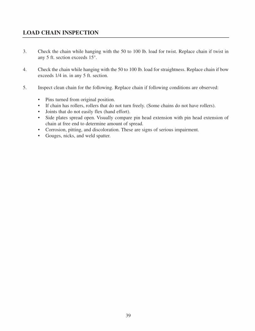
3. Check the chain while hanging with the 50 to 100 lb. load for twist. Replace chain if twist inany 5 ft. section exceeds 15°.
4. Check the chain while hanging with the 50 to 100 lb. load for straightness. Replace chain if bowexceeds 1/4 in. in any 5 ft. section.
5. Inspect clean chain for the following. Replace chain if following conditions are observed:
• Pins turned from original position.• If chain has rollers, rollers that do not turn freely. (Some chains do not have rollers).• Joints that do not easily flex (hand effort).• Side plates spread open. Visually compare pin head extension with pin head extension of
chain at free end to determine amount of spread.• Corrosion, pitting, and discoloration. These are signs of serious impairment.• Gouges, nicks, and weld spatter.
39

Only authorized replacement load chain, with design specifications established by the hoist manufac-turer, should be used when replacing load chain on the hoist. Load chain is specifically designed for aparticular hoist. Load chain from one manufacturer should not be used on a hoist manufactured by adifferent manufacturer.
When replacing load chain, inspect the chain sprockets and all mating parts such as chain guides andchain strippers. Sprockets that have scored pockets, cracked or broken flanges, excessive pocket wear,or sharp edges from wear should be replaced. Guides and strippers that are worn or damaged should bereplaced.
Load chain should be replaced in accordance with the instructions outlined in the manual furnished bythe manufacturer with the hoist. The original reeving arrangement of the hoist must be followed whenreplacing load chain.
Load chain links that pass over the hoist drive load sprocket on edge (alternate to those links that lieflat in the sprocket pockets) shall be installed (unless otherwise recommended by the hoist manufac-turer) with the welds away from the center of the drive sprocket.
Load chain shall be installed without any twist between the hoist and load block or between hoist orload block and an anchored end connection on either the loaded side or the slack side of the load chain.
Load chain should be maintained in a lubricated condition.
DO NOT REPAIR LOAD CHAIN BY WELDING OR HEATING.
LOAD CHAIN REPLACEMENT
40

WEB STRAP INSPECTION
Web strap inspection criteria for scheduled frequent and periodic inspections are provided as follows.These criteria should also be used if the daily visual inspection by the operator indicates that a moredetailed inspection is required.
1. Remove the web strap from the drum to permit examination of its entire length.2. Examine visually for obvious gross damage such as melting or charring, acid or caustic burns,
weld spatter, broken stitching, cuts or tears, damaged eyes or fittings, abrasive wear, knots andnarrowing due to overloading.
3. Examine visually for rapid deterioration at web strap sections in contact with saddles, equaliz-er sheaves, and other sheaves where strap travel is limited; at sections of web strap near termi-nal ends where broken threads or cuts may be evident; at web strap sections subject to reversebends; and at web strap sections that are normally hidden during visual inspections such as partspassing over sheaves.
Only authorized web strap with design specifications established by the hoist manufacturer should beused when replacing web strap on the manually lever operated hoist. Web strap from one manufactur-er should not be used on a hoist manufactured by another manufacturer.
When replacing the web strap make certain that mating hardware items are thoroughly inspected forexcessive wear, corrosion, damage, and distortion.
Web strap shall be installed without twists between the hoist and load block or anchored ends.
WEB STRAP REPLACEMENT
41

The load controlling mechanism of manually lever operated hoists perform the following functionsunder normal operating conditions and with test loads up to 125% of rated load.
• Stop and hold the load when the lever force is removed and the lever stroke has beencompleted.
• Provide for incremental movement of the load when lifting or lowering.
The hoist braking system / ratchet and pawl operation on hoists in regular service should be checkedwithout load on the hook by the operator at the start of each shift, or the first time the hoist is to beoperated during each shift. The hoist braking system should be checked during scheduled frequent andperiodic inspections.
Every hoist manufacturer has a braking system / ratchet and pawl design that is unique in the mannerin which it operates and performs. Therefore, general guidelines for testing and adjusting all hoists can-not be outlined. Refer to the manual furnished by the manufacturer with the hoist for testing procedures,inspection, adjustment, and replacement of components of the braking system / ratchet and pawl oper-ation.
LOAD CONTROLLING MECHANISM – HOIST BRAKINGSYSTEM/RATCHET AND PAWL OPERATION
42

OPERATIONAL TEST
As mandated in B30.21, all altered or repaired hoists, or hoists that have not been used for the past 12months, shall be tested before being placed in service by or under the direction of a designated person.
All functions of the hoist shall be checked with the hoist suspended in the unloaded state. Some hoistsmay require a small load or pull on the load hook to test the lowering motion.
After testing in the unloaded state, a load of at least 100 lbs. (46 kg.) times the number of load sup-porting parts of tensioning medium shall be applied to the hoist in order to check for proper load con-trol (brake operation or ratchet and pawl operation).
LOADTEST
As mandated in B30.21, all hoists in which load sustaining parts have been altered, replaced, or repairedshall be tested statically or dynamically by or under the direction of an appointed person and a recordof such test shall be made.
The applied test load shall be at least equal to the rated load, or greater, as recommended by the hoistmanufacturer (refer to hoist manual). Note that the replacement of the tensioning medium (only) isspecifically excluded from this load test requirement. However, all functions of the hoist must bechecked (refer to Operational Test section) prior to putting the hoist back in service.
Note also that test anchorages or suspensions must be approved by a qualified person.
HOIST TESTING
43
APPENDIX A
abnormal operating conditions: environmental conditions that are unfavorable, harmful, or detri-mental to or for the operation of a hoist, such as excessively high or low ambient temperatures, expo-sure to weather, corrosive fumes, dust laden or moisture laden atmospheres, and hazardous locations.
appointed: assigned specific responsibilities by the employer or the employer’s representative.
block, load: the assembly of hook or shackle, swivel, bearings, sheaves, sprockets, pins, and framesuspended by the load chain, wire rope, or web strap. This shall include any appurtenances reeved inthe load chain, wire rope, or web strap.
brake: a device for retarding and stopping motion of the load (see load controlling mechanism).
chain, load: the load-bearing chain in a hoist.
chain, roller: a series or alternately assembled roller links and pin links in which the pins articulateinside the bushings and the rollers are free to turn on the bushings. Pins and bushings are press fit intheir respective link plates.
chain, rollerless: a series of alternately assembled roller links and pin links in which the pins articu-late inside the bushings with rollers on the bushing omitted. Pins and bushings are press fit in theirrespective link plates.
chain, welded link: a chain consisting of a series of interwoven links formed and welded.
designated person: a person selected or assigned by the employer or the employer’s representative asbeing competent to perform specific duties.
drum: the cylindrical member around which the wire rope or web strap is wound for lifting and low-ering the load.
friction brake: see load controlling mechanism
guide, chain: a means to guide the load chain at the load sprocket.
guide, web strap: a means to guide the web strap at the load sprocket (drum).
DEFINITIONS OF VARIOUS HOIST TERMS
44

APPENDIX A
guide, wire rope: a means to guide the wire rope at the load sprocket (drum).
hoist, lever operated: a lever operated manual device used to lift, lower, or pull a load and to applyor release tension.
hook latch: a mechanical device to bridge the throat opening of a hook, but not to support the load.
load: the total superimposed weight on the load block or hook.
load, rated: the maximum load for which a hoist is designated by the manufacturer.
load controlling mechanism: a mechanism that functions automatically to hold and control the load.In each of the following general types, a reciprocating force must be applied to the hoist lever to lowerthe load.
friction brake type: an automatic type of brake used for holding and controlling loads. Thisunidirectional device requires a force applied to the operating lever to lower the load, but doesnot impose additional lever pull when lifting the load.ratchet and pawl type: a load controlling mechanism consisting of interlocking pawl(s) andratchet that act to hold the load by mechanical engagement.
load hook: the hook used to connect the load to the hoist.
normal operating conditions: conditions during which a hoist is performing functions within thescope of the original design.
operating lever: the lever or handle provided to operate the hoist.
overload: any load greater than the rated load.
overtravel restraint: a device used to prevent the slack load chain from inadvertently being loweredpast the load sprocket.
parts (lines): number of lines of chain, wire rope, or web strap supporting the load block or hook.
pawl: a device for holding the machinery against undesired rotation by engaging a ratchet.
DEFINITIONS OF VARIOUS HOIST TERMS
45

APPENDIX A
qualified person: a person who, by possession of a recognized degree in an applicable field, or cer-tificate of professional standing, or who, by extensive knowledge, training, and experience, has suc-cessfully demonstrated the ability to solve or resolve problems relating to the subject matter and work.
ratchet: a toothed member for engagement with the pawl.
reeving: a system in which the chain, wire rope, or web strap travels around sprockets (drums) andsheaves.
rope: refers to wire rope unless otherwise specified.
shall: this word indicates that the rule is mandatory and must be followed.
sheave: a grooved wheel or pulley used with a rope or chain to change direction and point of applica-tion of a pulling force.
should: this word indicates that the rule is a recommendation, the advisability of which depends onthe facts in each situation.
sprocket, idler: a freely rotating device that changes the direction of the load chain, wire rope, or webstrap.
sprocket, load: a hoist component that transmits motion to the load chain, wire rope, or web strap.This component is sometimes called the load wheel, load sheave, pocket wheel, chain wheel, ordrum.
strap, web: a fabric woven of high tenacity synthetic yarns.
stripper: a device that aids the load chain in leaving the load sprocket.
DEFINITIONS OF VARIOUS HOIST TERMS
46
APPENDIX B
HMI Recommended Practices – Manually Lever Operated Hoists
HMI Lever Operated Hoist Operators Manual
Publisher: Hoist Manufacturers Institute8720 Red Oak Blvd., Suite 201Charlotte, NC 28217
ASME HST-3-1999 Performance Standard for Manually Lever Operated Chain Hoists
ASME B30.9-1996 Safety Standard, Slings
ASME B20.10-1999 Safety Standard, Hooks
ASME B30.21-1999 Safety Standard, Manually Lever Operated Hoists
ASME B29.24M-1995 Roller Load Chains for Overhead Hoists
Publisher: The American Society of Mechanical EngineersThree Park AvenueNew York, NY 10016
ASME Order Department22 Law DriveBox 2900Fairfield, NJ 07007-2900
HOIST REFERENCE DOCUMENTS AND STANDARDS
47

APPENDIX C
COMPANY ______________________________________________________________________
MANUALLY LEVER OPERATED HOIST INSPECTION REPORT (FORM L1)SHEET 1 OF 1
Inspection Date: _______________ Inspector: __________________________________________
Equipment Type: ____________________________________________________________________
Equipment Location andNumber: __________________________________________________________________________
HOISTMfg ______________________________S/N ______________________________Cap ______________________________
ACTION: (___) Pass Inspection(___) OK to Use, Maintenance Required as Noted in Comments(___) Fail Inspection. Remove From Service Until Correction Action
Required as Noted in Comments is Corrected.
COMMENTS (Use Additional Sheets as Required):
Forms Attached: (___) No. L2, Manually Lever Operated Hoist Inspection Form(___) No. L3, Wire Rope Inspection Form(___) No. L4A, Link Load Chain Inspection Form(___) No. L4B, Roller Load Chain Inspection Form(___) No. L5, Hook Inspection Form(___) No. L6, Web Strap Inspection Form
Signature and Date of Inspector: ______________________________________________________
Signature and Date of Supervisor: ______________________________________________________
SAMPLE REPORT FORM
48

APPENDIX C
COMPANY ______________________________________________________________________
MANUALLY LEVER OPERATED HOIST INSPECTION REPORT (FORM L2)SHEET 1 OF 3
Date:______________________________S/N: ______________________________
SAMPLE REPORT FORM
49
ITEMNO.
DESCRIPTION OFDAMAGE TO LOOK FOR PASS
NEEDSATTN. COMMENTS
L2.1
All Functional OperatingMechanisms:
Maladjustment that interfereswith proper operation.Unusual sounds.
L2.2
Braking / Ratchet and PawlMechanism:
Slipping under load.Difficult to release.
L2.3.1
Brake Parts:Brake Discs:
Glazing.Oil contamination.
L2.3.2
Ratchet and Pawl:Pawls and Pawl Springs:
Broken, Worn, Corroded, andStretched
L2.4
Tensioning Medium EndConnections:
Looseness, Cracks, Damage,Distortion
L2.5Tensioning Medium:Refer to Inspection Report FormL3, L4, or L6 as appropriate
L2.6 Reeving:Kinks, twists, looping
APPENDIX C
COMPANY ______________________________________________________________________
MANUALLY LEVER OPERATED HOIST INSPECTION REPORT (FORM L2)SHEET 2 OF 3
Date:______________________________S/N: ______________________________
Signature and Date of Inspector: ______________________________________________________
Signature and Date of Supervisor: ______________________________________________________
SAMPLE REPORT FORM
50
ITEMNO.
DESCRIPTION OFDAMAGE TO LOOK FOR PASS
NEEDSATTN. COMMENTS
L2.7Hooks:Refer to Hook Inspection Report Form L5
L2.8
Hook Retaining Devices:Not tight or secure, damageto nuts, collars, pins, welds,rivets used to secure hooks.
L2.9Hook Latch:
Missing, damaged, does notclose hook opening.
L2.10Hoist Frame:
Damage – gouges, distortion,cracks, bending.
L2.11Operating Lever:
Bends, cracks, broken, anddistortion.
L2.12Gears:
Wear, broken teeth, cracks,lubrication.
L2.13Bearing and Shafts:
Wear, distortion, cracks,loose, lubrication.
L2.14 Lubrication:Lack of amount, dirty.
L2.15Load Block:
Cracks, distortion, loosebolts, pins, or nuts.

APPENDIX C
COMPANY ______________________________________________________________________
MANUALLY LEVER OPERATED HOIST INSPECTION REPORT (FORM L2)SHEET 3 OF 3
Date:______________________________S/N: ______________________________
Signature and Date of Inspector: ______________________________________________________
Signature and Date of Supervisor: ______________________________________________________
SAMPLE REPORT FORM
51
ITEMNO.
DESCRIPTION OFDAMAGE TO LOOK FOR PASS
NEEDSATTN. COMMENTS
L2.16
Load Sprockets, Idlers, Guides,and Strippers:
Cracks, damage to groovesand wear
L2.17 Supporting Structure:Distortion, cracks.
L2.18All Bolts, Pins, and Nuts:
Missing, damaged, distortion,loose.
L2.19Load Limiting Devices:
Proper operation per manu-facturers specifications.
L2.20WARNING, Instruction Labels,and Load Markings
Missing, illegible

APPENDIX C
COMPANY ______________________________________________________________________
WIRE ROPE INSPECTION REPORT (FORM NO. L3)SHEET 1 OF 2
Date:______________________________S/N: ______________________________
Signature and Date of Inspector: ______________________________________________________
Signature and Date of Supervisor: ______________________________________________________
SAMPLE REPORT FORM
52
ITEMNO.
DESCRIPTION OFDAMAGE TO LOOK FOR PASS
NEEDSATTN. COMMENTS
L3.1
Rope Distortion:Kinking, crushing, unstranding,birdcaging, main strand dis-placement, or core protrusion.Replace if distortion exists.
L3.2Corrosion:
Replace if corrosion hascaused broken wires.
L3.3Broken or Cut Strands:
Replace immediately if onestrand is broken or cut.
L3.4
Broken or Cut Wires:Replace if twelve randomlydistributed broken wires inone rope lay or four brokenwires in one strand in onerope lay.
L3.5
Reduction of Outside Diameter:Loss of core support, wear ofouter wires, stretch. Refer toequipment manual or ASMEstandard for replacement data.
L3.6
End Connection or Fitting:Corroded, cracked, bent,damaged or worn. Loose ormissing bolts or low bolttorque.

APPENDIX C
COMPANY ______________________________________________________________________
WIRE ROPE INSPECTION REPORT (FORM NO. L3)SHEET 2 OF 2
Date:______________________________S/N: ______________________________
Signature and Date of Inspector: ______________________________________________________
Signature and Date of Supervisor: ______________________________________________________
SAMPLE REPORT FORM
53
ITEMNO.
DESCRIPTION OFDAMAGE TO LOOK FOR PASS
NEEDSATTN. COMMENTS
L3.7
Broken Wires at Socketed or Swaged End Fitting:
Replace if two broken wiresat fitting.
L3.8 Rope at End Fitting:Rope pulling through fitting.
L3.9
Sheaves:Damage to grooves, flanges,and bearings, wear, distortionand cracks.
L3.10Drum:
Damage to grooves, wear,distortion, cracks.
APPENDIX C
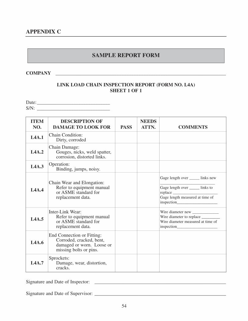
COMPANY ______________________________________________________________________
LINK LOAD CHAIN INSPECTION REPORT (FORM NO. L4A)SHEET 1 OF 1
Date:______________________________S/N: ______________________________
Signature and Date of Inspector: ______________________________________________________
Signature and Date of Supervisor: ______________________________________________________
SAMPLE REPORT FORM
54
ITEMNO.
DESCRIPTION OFDAMAGE TO LOOK FOR PASS
NEEDSATTN. COMMENTS
L4A.1 Chain Condition:Dirty, corroded
L4A.2Chain Damage:
Gouges, nicks, weld spatter,corrosion, distorted links.
L4A.3 Operation:Binding, jumps, noisy.
L4A.4
Chain Wear and Elongation:Refer to equipment manualor ASME standard forreplacement data.
Gage length over _____ links new___________________________Gage length over _____ links toreplace ______________________Gage length measured at time ofinspection____________________
L4A.5
Inter-Link Wear:Refer to equipment manualor ASME standard forreplacement data.
Wire diameter new _____________Wire diameter to replace _________Wire diameter measured at time ofinspection____________________
L4A.6
End Connection or Fitting:Corroded, cracked, bent,damaged or worn. Loose ormissing bolts or pins.
L4A.7Sprockets:
Damage, wear, distortion,cracks.
APPENDIX C
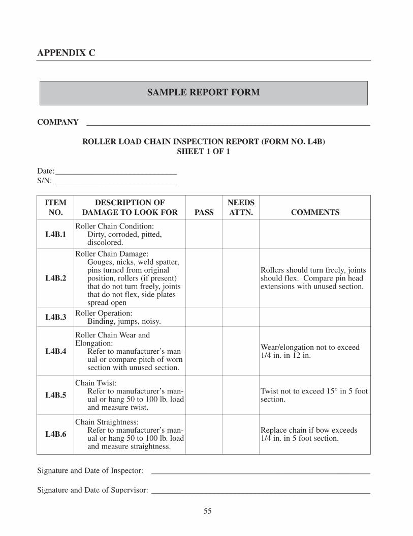
COMPANY ______________________________________________________________________
ROLLER LOAD CHAIN INSPECTION REPORT (FORM NO. L4B)SHEET 1 OF 1
Date:______________________________S/N: ______________________________
Signature and Date of Inspector: ______________________________________________________
Signature and Date of Supervisor: ______________________________________________________
SAMPLE REPORT FORM
55
ITEMNO.
DESCRIPTION OFDAMAGE TO LOOK FOR PASS
NEEDSATTN. COMMENTS
L4B.1Roller Chain Condition:
Dirty, corroded, pitted,discolored.
L4B.2
Roller Chain Damage:Gouges, nicks, weld spatter,pins turned from originalposition, rollers (if present)that do not turn freely, jointsthat do not flex, side platesspread open
Rollers should turn freely, jointsshould flex. Compare pin headextensions with unused section.
L4B.3 Roller Operation:Binding, jumps, noisy.
L4B.4
Roller Chain Wear andElongation:
Refer to manufacturer’s man-ual or compare pitch of wornsection with unused section.
Wear/elongation not to exceed1/4 in. in 12 in.
L4B.5
Chain Twist:Refer to manufacturer’s man-ual or hang 50 to 100 lb. loadand measure twist.
Twist not to exceed 15° in 5 footsection.
L4B.6
Chain Straightness:Refer to manufacturer’s man-ual or hang 50 to 100 lb. loadand measure straightness.
Replace chain if bow exceeds1/4 in. in 5 foot section.

APPENDIX C
COMPANY ______________________________________________________________________
HOOK INSPECTION REPORT (FORM NO. L5)SHEET 1 OF 1
Date:______________________________S/N: ______________________________
Signature and Date of Inspector: ______________________________________________________
Signature and Date of Supervisor: ______________________________________________________
SAMPLE REPORT FORM
56
ITEMNO.
DESCRIPTION OFDAMAGE TO LOOK FOR PASS
NEEDSATTN. COMMENTS
L5.1
Throat Opening:Replace if opening exceeds15% of new hook. Refer toequipment manual or ASMEstandard for replacement data.
Throat opening new _____________Throat opening to replace _____________________________________Throat opening measured at time ofinspection ____________________
L5.2
Hook Depth at Load BearingPoint:
Replace if wear exceeds 10%of new hook. Refer to equip-ment manual or ASME stan-dard for replacement data.
Hook depth new _______________Hook depth to replace ___________Hook depth measured at time ofinspection ____________________
L5.3
Twist:Replace if bend or twistexceeds 10° from plane ofunbent hook.
L5.4Hook Damage:
Gouges, nicks, weld spatter,corrosion, cracks, distortion.
L5.5
Hook Latch:Missing, not operative, doesnot close throat opening,damaged.
L5.6 Retaining Members:Damaged, loose.
L5.7 Bearing:Binding, lack of lube.

APPENDIX C
COMPANY ______________________________________________________________________
WEB STRAP INSPECTION REPORT (FORM NO. L6)SHEET 1 OF 1
Date:______________________________S/N: ______________________________
Signature and Date of Inspector: ______________________________________________________
Signature and Date of Supervisor: ______________________________________________________
SAMPLE REPORT FORM
57
ITEMNO.
DESCRIPTION OFDAMAGE TO LOOK FOR PASS
NEEDSATTN. COMMENTS
L6.1
Web Strap (entire length):Melting/charring, acid/caus-tic burns, weld spatter, bro-ken stitching, cuts and tears,damaged eyes, abrasive wear,knots, narrowing.
L6.2
Web Strap- sections in contactwith saddles, equalizer sheaves,other sheaves where travel islimited:
Rapid deterioration, wear.
L6.3
Web Strap – sections at or nearterminal ends:
Broken threads, cuts, andrapid deterioration and wear.
L6.4Web Strap – sections subject toreverse bending:
Rapid deterioration, wear.
L6.5
Web Strap – Sections that arehidden normally, such as thosewhich pass over sheave:
Rapid deterioration, wear.