LEVER HOIST - ACI Hoist and...
16
LEVER HOIST OPERATING, MAINTENANCE, & PARTS MANUAL ACI Hoist & Crane 689 S.W. 7 th Terrace Dania, FL 33004 Phone: 954 -367-7116 Fax: 954-272-0334 www.ACIHoist.com
Transcript of LEVER HOIST - ACI Hoist and...
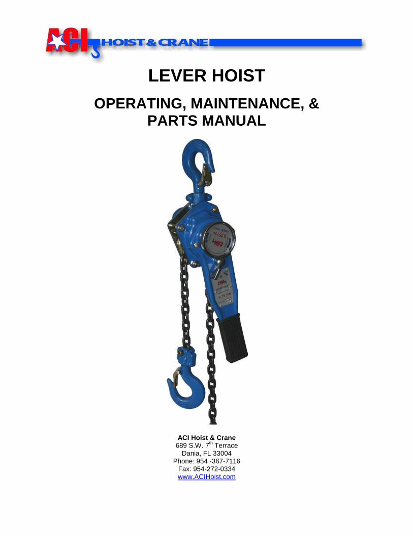
LEVER HOIST
OPERATING, MAINTENANCE, & PARTS MANUAL
ACI Hoist & Crane 689 S.W. 7
th Terrace
Dania, FL 33004 Phone: 954 -367-7116
Fax: 954-272-0334 www.ACIHoist.com

2

3
Table of Contents SECTION PAGE
1 General Information 5
1.1 Hoist Construction 5
2 Safety Precautions 5-6
2.1 Terms & Summary 5
2.2 Safety Rules 6
3 Preparation & Procedures 7
3.1 Prepare for Use 7
3.2 Attachment Points 7
3.3 Mounting the Hoist 7
3.4 Pre-Operational Checks & Trial Operation 7
4 Operating Instructions 8
4.1 Hoisting (Pulling & Lifting) & Lowering 8
4.2 Hoist Operation: Free Chain 8
4.3 Load Limit Warning Handle Option 8
5 Precautions While operating 9
5.1 Warnings 9
5.2 Attaching the Load 9
6 Routine Care, Inspection, & Maintenance 10-13
6.1 General 10
6.2 Inspection Classification 10
6.3 Frequent Inspection 11
6.4 Periodic Inspection 11
6.5 Inspection Schedule 11
6.6 Chain Inspection 12
6.7 Hook Inspection 12
6.8 Reject Opening 12
6.9 Storage 12
6.10 Lubrication 12-13
7 Trouble-Shooting Chart 13
8 Lever Hoist: Dimensions & Specifications 14
9 Spare Parts: Exploded View 15-16
9.1 Parts List 16
10 ACI Warranty 16

4
5
1.0: GENERAL INFORMATION
This document provides information and maintenance of ACI Lever Hoist/ Puller. Operators and persons maintaining the hoist should be familiar with this manual. Following the precautions, procedures and maintenance practices in this manual should ensure long and reliable operation. People responsible for the installation operation, and or maintenance of the hoisting equipment should be familiar with the American National Standard ANSI B30.21 for guidelines on the safe operation of lever hoists. That document contains rules on inspection requirements and records that may be required by some of the regulatory agencies.
1.1: HOIST CONSTRUCTION The Steel Body Lever Hoist/ Puller is a dependable way to accurately position heavy loads, loading and lifting freely suspended loads within the hoist’s rated load. The reversing lever and free-chain wheel provide an ease of control, even with work gloves. The hoist can be used in confined spaces due to the short handle and low handle chair.
2.0: SAFETY PRECAUTIONS
2.1: TERMS & SUMMARY This manual provides important information for personnel involved with the installation, operation, and maintenance of the HOIST. Although you may be familiar with hoist or similar equipment, it is strongly recommended that you read this manual before installing, operating or maintaining the product.
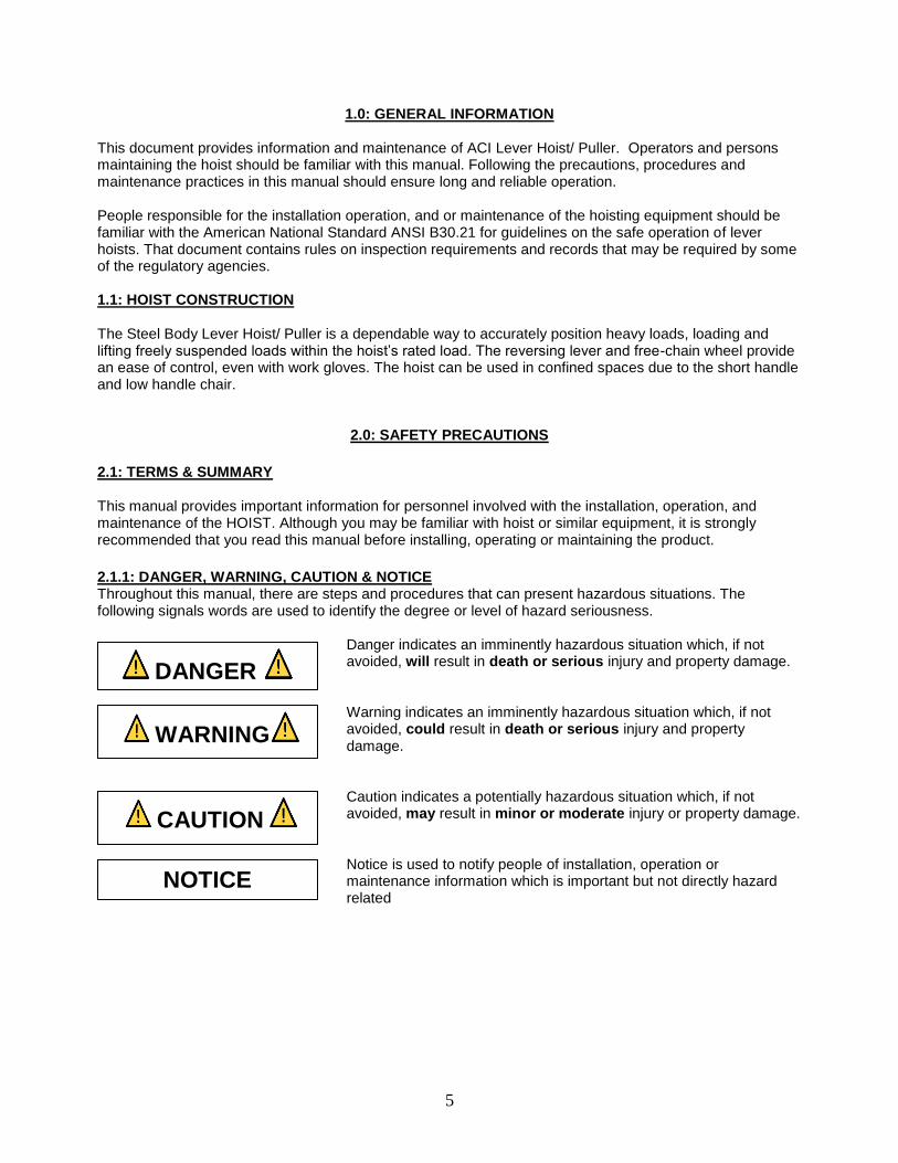
2.1.1: DANGER, WARNING, CAUTION & NOTICE Throughout this manual, there are steps and procedures that can present hazardous situations. The following signals words are used to identify the degree or level of hazard seriousness.
Danger indicates an imminently hazardous situation which, if not avoided, will result in death or serious injury and property damage.
Warning indicates an imminently hazardous situation which, if not avoided, could result in death or serious injury and property damage.
Caution indicates a potentially hazardous situation which, if not avoided, may result in minor or moderate injury or property damage.
Notice is used to notify people of installation, operation or maintenance information which is important but not directly hazard related
DANGER
WARNING
CAUTION
NOTICE

6
2.2: SAEFTY RULES Inspect the hoist for loose, broken or malfunctioning parts. Any hoist should be tagged “out of order” and taken out of service until the problem is corrected.
a. DO NOT overload the hoist. b. DO NOT exert more than the hand chain pull to lift rated load by one operator (see Table 1). The
hoist is designed to lift its rated capacity when a reasonable force is exerted. If effort appears to be excessive, recheck the load and use a larger capacity hoist if necessary.
c. DO NOT side load the hoist. Make sure to pull in the straight line between hooks. Side loading the hoist over a sharp corner may fracture the hoist housing, load block or hook.
d. Be sure there are NO twists in the chain. Make sure that the load chain is free to move and clear all obstructions. With multiple chained hoists the load hook can be turned one or more times causing the chain to twist.
e. DO NOT use the hoist from an unbalanced/unstable position. Operators should have firm footing or be secured before operating the hoist.
f. Before raising and/or pulling a load always make sure that the slings and other rigging have sufficient capacity to support the load, and are in good condition.
g. DO NOT STAND BENEATH A LOAD! DO NOT operate a load in a way to endanger
personnel. h. DO NOT leave the hoist with a suspended load. i. DO NOT wrap the load chain around the load. USE A SLING! j. DO NOT TIP-LOAD the hook, as this will exert undue strain, resulting in hook failure. k. The hoist is designed for manual operation by one person only. DO NOT use the hoist with and
other power besides the manual power from one person.
l. DO NOT USE HOIST TO LIFT, SUPPORT OR OTHERWISE TRANSPORT PEOPLE.
m. The hand chain has a safety latch. When the safety latch opens or deforms, stop immediately to find out the cause.
n. Hoists are designed to lift loads vertically and SHOULD NOT be used for horizontal or angle hoisting.
o. NEVER use the chain or hook as a ground welding. p. Use only parts and chains supplied by the authorized distributor.

7
3.0: PREPARATION & PROCEDURES 3.1: PREPARE FOR USE When unpacking the hoist, inspect carefully for any damage that may have occurred during shipping. Check for loose, missing, or damaged parts. Lubricate the chain along the whole length with a good quality chain and wire rope lubricant. Make sure the structures supporting the hoist are strong enough to support the entire rated load. 3.2: ATTACHMENT POINTS WARNING: Prior to attaching the hoist ensure that all attachment points, suspension components and supporting structure are adequate to support the hoist and its load. If necessary consult a professional that is qualified to evaluate the adequacy of the suspension location and its supporting structure. 3.3: MOUNTING THE HOIST
Hook Mounted to a Fixed Location – Attach the hoist’s top hook to the fixed suspension point.
Ensure that the fixed suspension point resets on the center of the hook’s saddle and that the hook’s latch is engaged.
3.4: PRE-OPERATIONAL CHECKS & TRIAL OPERATION
Confirm the adequacy of the rated capacity for all slings, chains, wire ropes and all other lifting attachments before use. Inspect all load suspension members damage prior to use and replace or repair all damages parts.
Verify and correct all chain irregularities prior to operating the hoist.
Record the hoist’s Model Number & Serial Number (from the plate on the hoist).
Ensure that the hoist is properly installed to a fixed point.
Ensure that all nuts, bolts, and split pins (cotter pins) are sufficiently fastened.
Confirm proper operation o Before operating read and become familiar with Operation. o Before Operating ensure that the hoist meets the Inspection, Testing, and Maintenance
requirements of ANSI/ASME B30.21. o Before operating ensure that nothing will interfere with the full range of the hoist’s operation.

8
4.0: OPERATING INSTRUCTIONS 4.1: HOISTING (PULLING & LIFTING) & LOWERING To lift or pull a load, turn the reversing lever to the UP position and move the handle in a clockwise direction. To lower a suspended load, turn the reversing lever to the DOWN position and move the handle in a counterclockwise direction. CAUTION: With no load on the hoist, reciprocating the handle may result in only a back and forth movement of the chain with no overall hook movement. When this happens, the chain may be positioned by applying a light pull in the chain with the free hand, or by using the free chain feature. 4.2: HOIST OPERATION: FREE CHAIN 4.2.1: PRINCIPLE
Free chaining allows the load chain to be moved freely because the brake is released under no load situations.
Pulling the free knob actuates the internal spring to release the mechanical brake allowing the load chain to be pulled in either direction to the desired length.
The brake is engaged during lowering or lifting the load. 4.2.2: OPERATION
DO NOT operate the hoist Free Knob while a load is applied to the hoist.
DO NOT touch the hoist Free Knob during lifting or lowering of the load.
ALWAYS check that the selector is placed in the proper position.
Set the Selector to the “N” position. The Selector is located under the Free Knob on the hand lever.
Pull the Free Knob pout. The Free Knob turns counterclockwise and “snaps” out.
Pull the load chain to move the hook to the desired position.
DO NOT pull the chain suddenly in the free chain mode. Excessive pulling may set the brake and not allow the load chain to move. If this occurs the hoist must be reset.
To reset the hoist to operate, rotate the Free Knob clockwise while pulling lightly on the load side chain. Once slack is removed, the Free Knob “snaps” in. This resets the brake and allows the hoist to be operated with the hand lever.
DO NOT attempt to use the free-chain feature while there is any load on the hoist.
4.2.3: LIFTING & LOWERING
LEVER HOIST OPERATION
Selector Position Lever Rotation Load Movement
UP Clockwise Lift
DOWN Counterclockwise Lower
4.3: LOAD LIMIT WARNING HANDLE OPTION
SIGNAL WARNINGS
Signal Color Load Status INSTRUCTIONS
Green Safe Load Continue Operation
Red Overload DO NOT Continue Operation

9
5.0: PRECAUTIONS WHILE OPERATING
5.1: WARNINGS
Do not lift or pull more than the rated capacity.
Do not use a handle extension (cheater bar). The hoist is designed to pull rated loads with low handle effort. If a cheater bar seems necessary to lift the load, the hoist is overloaded.
Stand clear of the load at all times. The operator should have sufficient room to use the hoist without endangering himself.
5.2: ATTACHING THE LOAD
1. Be sure there are no twists in the load chain as it enters the hoist. This condition should be constantly checked on double chain hoists because it is possible for the load block to be "capsized" or flipped over one or more times, putting twists in the chain. The presence of a twist may not be obvious when the hook block is in the lowered position, but can cause serious chain binding when the hook is in its fully raised position.
2. Never load on the end of the hook. Use attachments that will seat in the saddle of the hook 3. Make sure that slings and other rigging are in good condition and have sufficient capacity. Never
wrap the hoist chain around a load.
**DO NOT OPERATE THE HOIST FROM AN OFF-BALANCE POSITION. OPERATOR SHOULD HAVE FIRM FOOTING OR BE OTHERWISE SECURED BEFORE OPERATING
THE HOIST. Check the hoist each time it is used by lifting the load just clear of its supports and checking to be sure that the load is secure in the hook and that the hoist brake is holding the load without slipping.
Never raise the hook block into the bottom of the hoist or run the hook down until the slack chain is pulled tight.
Never attempt to free-chain the hoist with any load on the hook.
Do not leave a suspended load unattended.
Do not throw or drop the hoist, or drag it along the ground.
Do not use a damaged or malfunctioning hoist. Lifting a load with two hoists is not recommended. If unavoidable, care must be taken that neither hoist is overloaded.
10
6.0: ROUTINE CARE, INSPECTION, AND MAINTENANCE 6.1: GENERAL The inspection procedure herein is based on ANSI/ASME B30.21. The following definitions are from ANS/ASME B30.21 and pertain to the inspection procedure below.
Designated Person: a person selected or assigned as being competent to perform the specific duties to which he/she is assigned.
Qualified Person: a person who, by possession of a recognized degree or certificate of professional standing, or who, by extensive knowledge, training, and experience, has successfully demonstrated the ability to solve or resolve problems relating to the subject matter and work.
Normal Service: that distributed service which involves operation with randomly distributed loads within the related load limit, or uniform loads less than 65% of rated load for not more than 15% of the time.
Heavy Service: that service which involves operation within the rated load limit which exceeds normal service.
Severe Service: that service which involves normal or heavy service with abnormal operating conditions.
6.2: INSPECTION CLASIFICATION
TYPE DESCRIPTION
Initial Inspection Prior to initial use, all new, altered, or modified hoists shall be inspected by a designated person to ensure compliance with the applicable provisions of this manual
Inspection Classification
The inspection procedure for hoists in regular service is divided into two general classifications based upon the intervals at which inspection should be performed. The intervals in turn are dependant upon the intervals at which inspection should be performed. The intervals in turn are dependent upon the nature of the critical components of the hoist and the degree of their exposure to wear, deterioration, or malfunction. The two general classifications are herein designated as FREQUENT and PERIODIC, with respective intervals between inspections as defined below.
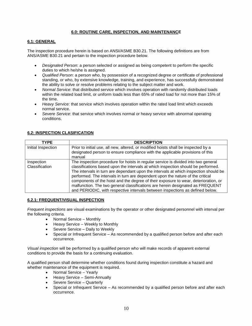
6.2.1: FREQUENT/VISUAL INSPECTION Frequent inspections are visual examinations by the operator or other designated personnel with interval per the following criteria.
Normal Service – Monthly
Heavy Service – Weekly to Monthly
Severe Service – Daily to Weekly
Special or Infrequent Service – As recommended by a qualified person before and after each occurrence.
Visual inspection will be performed by a qualified person who will make records of apparent external conditions to provide the basis for a continuing evaluation. A qualified person shall determine whether conditions found during inspection constitute a hazard and whether maintenance of the equipment is required.
Normal Service – Yearly
Heavy Service – Semi-Annually
Severe Service – Quarterly
Special or Infrequent Service – As recommended by a qualified person before and after each occurrence.
11
Written, dated and signed inspection reports should be maintained on all critical items; such as safety devices, brakes, hooks, ropes, chains, etc. All worn, damaged or malfunctioning parts should be repaired or replaced to maintain a SAFE operating hoist. Warning labels affixed to the hoist or trolley should be kept clean and visible at all times. Warning labels should be replaced if loose or illegible. 6.3: FREQUENT INSPECTION
Frequent Inspection
All functional operating mechanisms for proper operation and adjustment, maladjustment and unusual sounds.
Hoist braking system for proper operation
Hooks and latches in accordance with ANSI/ASME B30.10
Hook latch operation
Load chain reeving for compliance
Hoist Lever for bends and cracks
Hoist support for damage
6.4: PERIODIC INSPECTION
Periodic Inspection
Requirement of frequent inspection
Evidence of loose, bolts, nuts, or rivets.
Evidence of worn, corroded, cracked, or distorted parts such as load blocks, suspension housing, chain attachments, clevises, yokes, suspension bots, shafts, gears, bearings, pins, rollers and locking and clamping devices.
Evidence of damage to hook retaining nuts or collars and pins, and welds or rivets used to secure the retaining members.
Evidence of damage or excessive wear of load and idler sheaves
Evidence or worn, glazed or oil contaminated friction disks; worn pawls, cams or ratchet; corroded, stretched, or broken pawl springs in brake mechanism.
Evidence of damage to supporting structure
Function label on hoist for legibility
Warning label properly attached to the hoist and legible
End connections of load chain stopper link
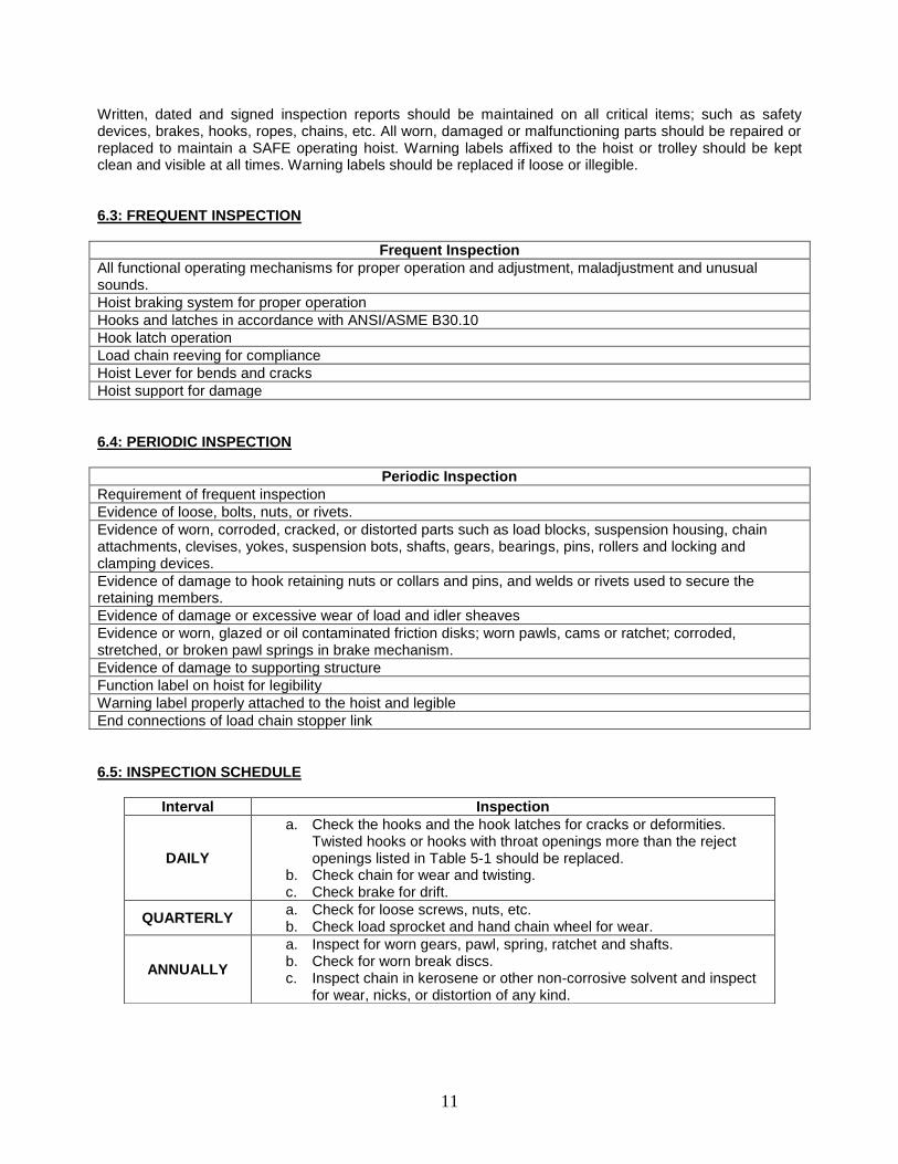
6.5: INSPECTION SCHEDULE
Interval Inspection
DAILY
a. Check the hooks and the hook latches for cracks or deformities. Twisted hooks or hooks with throat openings more than the reject openings listed in Table 5-1 should be replaced.
b. Check chain for wear and twisting. c. Check brake for drift.
QUARTERLY a. Check for loose screws, nuts, etc. b. Check load sprocket and hand chain wheel for wear.
ANNUALLY
a. Inspect for worn gears, pawl, spring, ratchet and shafts. b. Check for worn break discs. c. Inspect chain in kerosene or other non-corrosive solvent and inspect
for wear, nicks, or distortion of any kind.
12
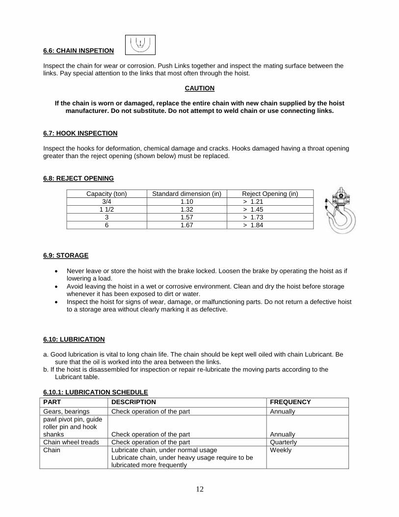
6.6: CHAIN INSPETION Inspect the chain for wear or corrosion. Push Links together and inspect the mating surface between the links. Pay special attention to the links that most often through the hoist.
CAUTION
If the chain is worn or damaged, replace the entire chain with new chain supplied by the hoist manufacturer. Do not substitute. Do not attempt to weld chain or use connecting links.
6.7: HOOK INSPECTION Inspect the hooks for deformation, chemical damage and cracks. Hooks damaged having a throat opening greater than the reject opening (shown below) must be replaced. 6.8: REJECT OPENING
Capacity (ton) Standard dimension (in) Reject Opening (in)
3/4 1.10 > 1.21
1 1/2 1.32 > 1.45
3 1.57 > 1.73
6 1.67 > 1.84
6.9: STORAGE
Never leave or store the hoist with the brake locked. Loosen the brake by operating the hoist as if lowering a load.
Avoid leaving the hoist in a wet or corrosive environment. Clean and dry the hoist before storage whenever it has been exposed to dirt or water.
Inspect the hoist for signs of wear, damage, or malfunctioning parts. Do not return a defective hoist to a storage area without clearly marking it as defective.
6.10: LUBRICATION a. Good lubrication is vital to long chain life. The chain should be kept well oiled with chain Lubricant. Be
sure that the oil is worked into the area between the links. b. If the hoist is disassembled for inspection or repair re-lubricate the moving parts according to the
Lubricant table.
6.10.1: LUBRICATION SCHEDULE
PART DESCRIPTION FREQUENCY
Gears, bearings Check operation of the part Annually
pawl pivot pin, guide roller pin and hook shanks
Check operation of the part
Annually
Chain wheel treads Check operation of the part Quarterly
Chain Lubricate chain, under normal usage Lubricate chain, under heavy usage require to be lubricated more frequently
Weekly

13
CAUTION
The brake surfaces must be kept free of any trace of oil or grease. Apply lubricant sparingly to the parts near the brake to avoid oil contamination of the brake.
6.10.2: LUBRICANTS THAT ARE RECOMMENDED
Part Lubricant
Gears, bearings, pawl pivot pin, guide roller pin, hook shanks.
Any good quality NLGI #2 grease
Chain. Chain Lubricant
Brake parts, ratchet teeth. Do Not Lubricate
7.0: TROUBLE-SHOOTING CHART
Circumstance Cause How to Correct
Pinion shaft does not return to position after free chaining.
1. Wear of the spline section of the pinion shaft. 2. Deformation or damage of the return spring. 3. Mechanism fouled with foreign matter such as dirt and dust.
Replace with new parts.
Replace with new parts.
Disassemble and clean.
Slip caused by ineffective braking. 1. Worn out friction discs. 2. Oil on the braking surface. 3. Incorrect assembly of the brake system.
Replace with new ones.
Disassemble and clean.
Assemble correctly referring to page 8.
Load dropped while lowering. 1. Damaged friction discs. 2. Foreign matter in the braking system.
Replace with new ones.
Disassemble and clean.
Jammed operating handle. Over-tightening of the brake. Operate the lever hoist as if lowering a load.
Noises during hoisting and lowering operation.
Wear or deformation of the load chain and load sheave.
Replace with new parts.
Operating handle becomes difficult to operate during lifting or
lowering operation.
1. Over-hoisting or over-lowering. 2. Twist in the load chain causing it to get caught between load sheave and from the load chain.
Operate the hoist in opposite direction.
Operate the hoist in opposite direction and remove the twist
load chain guide.

14
8.0: LEVER HOIST: DIMENSIONS & SPECIFICATION
0.75T, 1.5T & 3T
6T
Model LH-015 LH-030 LH-060 LH-120
Capacity (tons) 3/4 1 1/2 3 6
No. of columns of load chain 1 1 1 2
Handle pull rated loads (lbs) 60 66 75 83
Distance (in)
A 5.83 6.81 7.87 7.87
B 3.43 3.90 4.41 4.41
C 5.20 5.71 7.83 9.06
D 10.94 14.88 15.28 15.28
E 1.1 1.3 1.6 1.7
Ø 1.40 1.67 1.97 2.09
H 13.0 15.7 20.5 25.2
Net weight (lbs.) for 5 ft lift
15.21 24.0 45.6 62.0
Packing measurement (in) 15 x 5 x 6.7 18.9 x 5.1 x 7.9 21.8 x 7.3 x 8.9 21.8 x 7.9 x 8.9
Extra weight per feet of extra lift (lbs.)
0.53 0.94 1.48 2.96
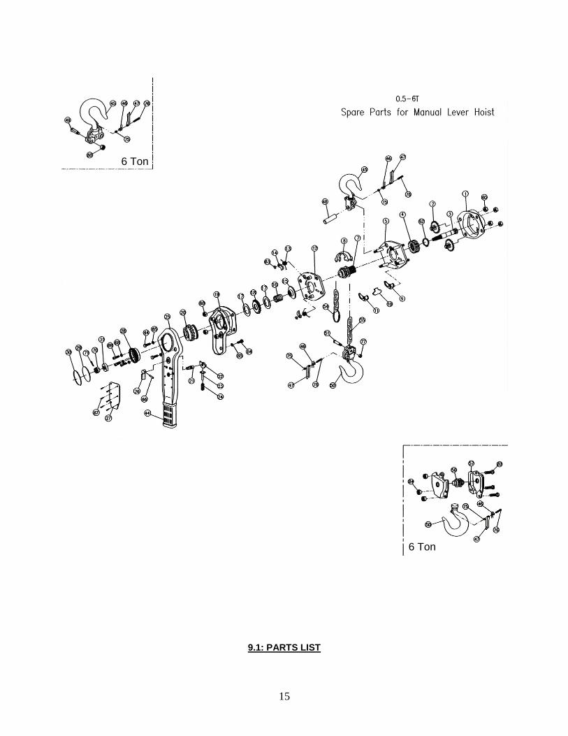
9.0: SPARE PARTS: EXPLODED VIEW
15
9.1: PARTS LIST
6 Ton
6 Ton

16
1. Gear case assembly 24.Change over spring 63. Snap ring
2. Driver shaft assembly 25. Lever handle assembly 64. Screw
3. Drive shaft 26. Selector lever 65. Washer
4. Splined gear 27. Name plate 66. Spring pin
5. Side plate assembly A 28. Hand wheel 67. Rivet
7. Load sheave 29. Cover 68. Spring washer
8. Guide plate 30. Retainer wire 69. Screw
9. Chain leader A 31. Bushing 70. Castle nut
10. Stripper 44. Lever handle cover 71. Split pin
11. Chain leader B 45. Hook assembly 75. Prevailing torque. Type nut
12. Side plate assembly B 46. Double spring 76. Screw
13. Pawl spring 47. Safety latch 77. Prevailing torque. Type nut
14. Pawl 48. Top pin 82. Screw
15. Disk hub 49. Top Chain pin 84. Prevailing torque. Type nut
16. Free spring 50. Bottom hook assembly
17. Friction disk 51. Chain pin
18. Ratchet disk 54. Chain ring
19. Lever cover assembly 55. Load chain
20. Change over gear 56. Idler sheave assembly
21. Selector shaft 57. Hook block component
22. Change over pawl 60. Prevailing torque. Type nut
23. Spring shaft 62. Snap ring
10.0: ACI WARRANTY
WARRANTY
Every hoist is thoroughly inspected and tested before it is shipped from the factory. If any problem develops within one year return the complete hoist prepaid to the factory. If an inspection reveals that the problem is caused by defective workmanship or material, repairs will be made without charge and the hoist will be returned, transportation prepaid. This warranty does not cover: (a) deterioration caused by normal wear, abuse, eccentric or side loading, overloading, chemical or abrasive actions, improper maintenance or excessive heat; (b) problems resulting from repairs, modifications or alterations made by people other than factory or ACI representative; (c) the hoist has been abused or damaged due to an accident; (4) repair parts or accessories other than ACI equipment are used on the hoist. Equipment and accessories not of the seller’s manufacture are warranted only to extent that they are warranted by the manufacturer. EXCEPT AS STATED HERE, ACI MAKES NO OTHER WARRANTIES, EXPRESS OR IMPLIED, INCLUDING WARRANTIES FOR A PARTICULAR PURPOSE.