Manual, Nordson/Drexelbrook Material Level Control...
12
Nordson/Drexelbrook Material Level Control Kit NORDSON CORPORATION. AMHERST, OHIO. USA Publication No. 104 554A
Transcript of Manual, Nordson/Drexelbrook Material Level Control...

Nordson/Drexelbrook Material Level Control Kit
NORDSON CORPORATION. AMHERST, OHIO. USA Publication No. 104 554A

Nordson Corporation welcomes requests for information, comments and inquiries about its products.
Address all correspondence to
Nordson Corporation 11475 Lakefield Drive
Duluth, GA 30136
Notice
This is a Nordson Corporation publication which is protected by copyright. No part of this document may be photocopied, reproduced, or translated to another language without the prior written consent of Nordson
Corporation. The information contained in this publication is subject to change without notice.
Trademarks
AquaGuard, Blue Box, Control Coat, Equi=Bead, FloMelt, FoamMe’lt, FoamMix, Helix, Hot Shot, Hot Stitch, Meltex, MicroSet, MultiScan, Nordson, the Nordson logo, OmniScan, iPorous Coat, Posi-Stop, RBX, Sure-Bond,
UniScan, UpTime, and Versa-Spray are registered trademarks of Nordson Corporation.
BetterBooksM, CF, Controlled Fiberization, Easy-Screen, Fibenelt, I-lo-Tracker, PrintGuard, and Package of Values are trademarks of Nordson Corporation.
Manual (S) 46.7
Issued 4/87 Q 1987 Nordson Corporation
All Rights Reserved
Publication No. 104 554A

THE NORDSON/DREXELBROOK MATERIAL LEVEL CONTROL KIT
INTRODUCTION The Nordson/Drexelbrook Material Level Control Kit automatically regulates the amount of hot melt material supplied to one or more applicator unit(s) from a single bulk melter feeder. This eliminates the need for an equipment operator to manually start and stop the filling process.
PARTS LISTS There are several versions of the Nordson/Drexelbrook Material Level Control Kit available:
Item No. Part No. Description Req'd
805 634 Level Control Assembly jw/o Mounting Hardware Ref
1 803 320 . Condulet w/Fitting 1 2 803 321 n Cable, Drexelbrook 25 ft 3 803 322 9 Control, Level, Electronic Unit 1 4 803 323 . Probe, Level Control, 10.5 in. 1
Item No. Part No. Description Req'd
1 805 634 2 803 316 3 981 029 4 803 315 5 981 123 6 803 317 7 981 225 8 983 140 9 803 314 10 973 399 11 972 620
12
13 983 102
803 318
972 619
Level Control Kit w/Mounting Hardware (fits HM XI, XVIII, FMlOlA, 1OlB and 151)
n Level Control Assembly (see above) n Cover, Enclosure . Screw, Fillister Head, 6-32 x 0.50 in. . Cylinder, Enclosure n Screw, Round Head, lo-24 x 0.63 in. n Cover, Bleed Hole n Screw, Socket Head, l/4-20 x 0.63 in. n Lockwasher, Split, 0.25 in. n Cover, Tank 9 Bushing, Pipe, Hyd, 0.75 x 0.50 in. n Connector, Male, Hyd, 37 deg,
1 l/16-12 x 0.50 in. n Connector, Male, Hyd, 37 deg,
g/16-18 x 0.50 in. n Lockwasher, Split, No. 6
Ref
1 1 8 1 4 1 8 8 1 1
1
1 8
(S)46.7mIssued 4/87@Nordson Corporation 1987 Publication No. 104 554A

2
Item No. Part No. Description Req'd
710 689 Level Control Assembly w/o Mounting Hardware Ref
1 803 320 . Condulet w/Fitting 1
2 803 321 n Cable, Drexelbrook 25 ft
3 710 690 . Control, Level, Electronic, Unit 1
4 710 691 . Probe, Level Control, 18 in. 1
Item No. Part No. Description Req'd
803 471 Level Control Kit w/Mounting Hardware Ref (fits HM XIIA, FM 103A, 103B and 153)
9 972 620
803 099 710 689 981 906 983 140 803 101 981 159 973 399 972 619
. Plate, Mounting, Level Control n Level Control Assembly (see above) . Screw, Socket Head, Cap, l/4-20 x 0.75 in. . Lockwasher, Split, 0.125 in. . Cover, Hole . Screw, Pan Head, lo-3:2 x 0.50 in. . Bushing, Pipe, Hyd, 0.75 x 0.50 in. n Connector, Male, 37 deg,
g/16-18 x 0.50 in. n Connector, Male, 37 deg,
1 l/16-12 x 0.50 in.
W46 7 . .Issued 4/87WNordson Corporation 1987 Publication No. 104 554A

3
SAFETY PRECAUTIONS
PROBE INSTALLATION Kits P/N 803 471 and P/N 710 689
3.4 ’
A
a 3
A
WARNING: Wear safety glasses, safety gloves (P/N 902 514), and protective clothing to prevent injury from hot applicator parts, splashed hot melt adhesive material and hot gun surfaces.
WARNING: This equipment contains energized electrical components with potentials that could be fatal. Only qualified personnel should operate this equipment. Lock out and tag electrical power to the bulk melter and applicator before beginning installation procedures.
CAUTION: Do not touch the hot melt equipment during operation. It is hot.
Kit P/N 710 689 requires user-supplied mounting hardware.
1. Replace the hinged lid on the applicator hopper cover with the level control kit mounting plate. Use three of the socket head screws and split lock washers provided in the level control kit.
2. Insert but do not secure the level control probe in either of the two 0.75 in. NPT holes in the mounting plate.
?
To Control Unit
5
Figure 1 -- Probe mounting details (Kits P/N 803
see parts lists on page 2 471 and 710 689);
(S)46.7mIssued 4/87@Nordson Corporation 1987 Publication No. 104 554A
4
PROBE INSTALLATION Kits P/N 803 471 and P/N 710 689
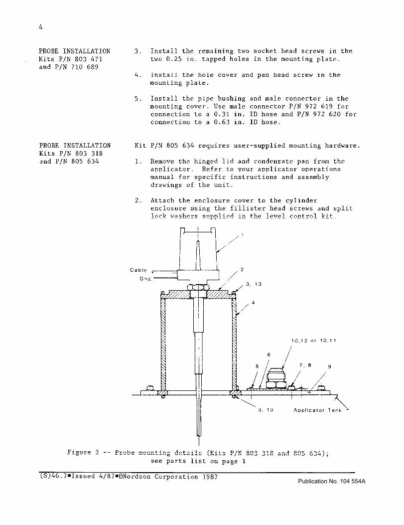
PROBE INSTALLATION Kits P/N 803 318 and P/N 805 634
3. Install the remaining two socket head screws in the two 0.25 in. tapped holes in the mounting plate.
4. Install the hole cover and pan head screw in the mounting plate.
5. Install the pipe bushing and male connector in the mounting cover. Use male connector P/N 972 619 for connection to a 0.3l in. ID hose and P/N 972 620 for connection to a 0.63 in. ID hose.
Kit P/N 805 634 requires user-supplied mounting hardware.
1. Remove the hinged lid and condensate pan from the applicator. Refer to your applicator operations manual for specific instructions and assembly drawings of the unit.
2. Attach the enclosure cover to the cylinder enclosure using the fillister head screws and split lock washers supplied in the level control kit.
10,12 or 10,ll
Appltcator Ta
Figure 2 -- Probe mounting details (Kits P/N 803 318 and 805 634); see parts list on page 1
(S)46.7mIssued 4/87@Nordson Corporation 1987 Publication No. 104 554A
PROBE INSTALLATION 3. Attach the enclosure cover/cylinder enclosure Kits P/N 803 318 assembly to the top of the applicator tank using and P/N 805 634 the fillister head screws and split lock washers (Continued) supplied in the level control kit.
4. Secure the tank cover to the unit using the socket head screws and standard lock washers supplied in the level control kit.
CONTROL UNIT INSTALLATION AND WIRING All Kits
5.
6,
Plug the tapped hole in the socket head screw
tank cover with another
Install the hole cover and round head screw.
7. Install the pipe bu,shing and male connector in the mounting cover. Use male connector P/N 972 619 for connection to a 0.31 in. ID hose and P/N 972 620 for connection to a 0.6.3 in. ID hose.
8. Insert but do not secure the level control probe in enclosure cover.
la. (Kits P/N 803 471 and 710 689) Mount the electronic control unit in a location as free as possible from vibration, corrosive atmosphere and potential mechanical damage. Then proceed to step 2 of this procedure.
lb. (Kits P/N 803 318 and 805 634) The electronic level control unit is enc:Losed in the probe condulet. Proceed to step 2 o:E this procedure.
2. Unscrew the control unit housing cap to control unit terminal block.
expose the
3. Couple the bulk melter hose to the male connector on the mounting plate or enclosure cover (for multiple applicator configurations, see MULTIPLE APPLICATORS).
4. Wire the control unit to the level control probe as shown in Figures 3 and 4. Note that the probe wire and tote shield wire are insulated as a single unit. The tote shield wire branches off just prior to end of cable.
5. Wire the control unit terminal marked GND to a ground connection.
(S)46.7mIssued 4/87=ONordson Corporation 1987 Publication No. 104 554A

Probe
connections
Power In (115 VAC 50180 Hz)
To bulk melter
terminals +l & l 2
!n! F Probe Rod
Figure 3 -- Level control probe and control unit installation (Kits P/N 803 471 and 710 689 shown)
6. Wire the control unit terminals 114 and #5 to the bulk melter per the following:
. Model 500: to TBl terminals #9 and #lo.
9 Model 5505: to TBl terminals #6 and #7.
. Model 5510: to TBl terminals #6 and #7.
. Model 5520: to TB2 terminal #6 and TBl terminal #17 (NOTE: Remove the factory-installed jumper wire that connects these two terminals).
7. Connect level control unit terminals #l and #2 to a 115 VAC, 60 Hz power source.
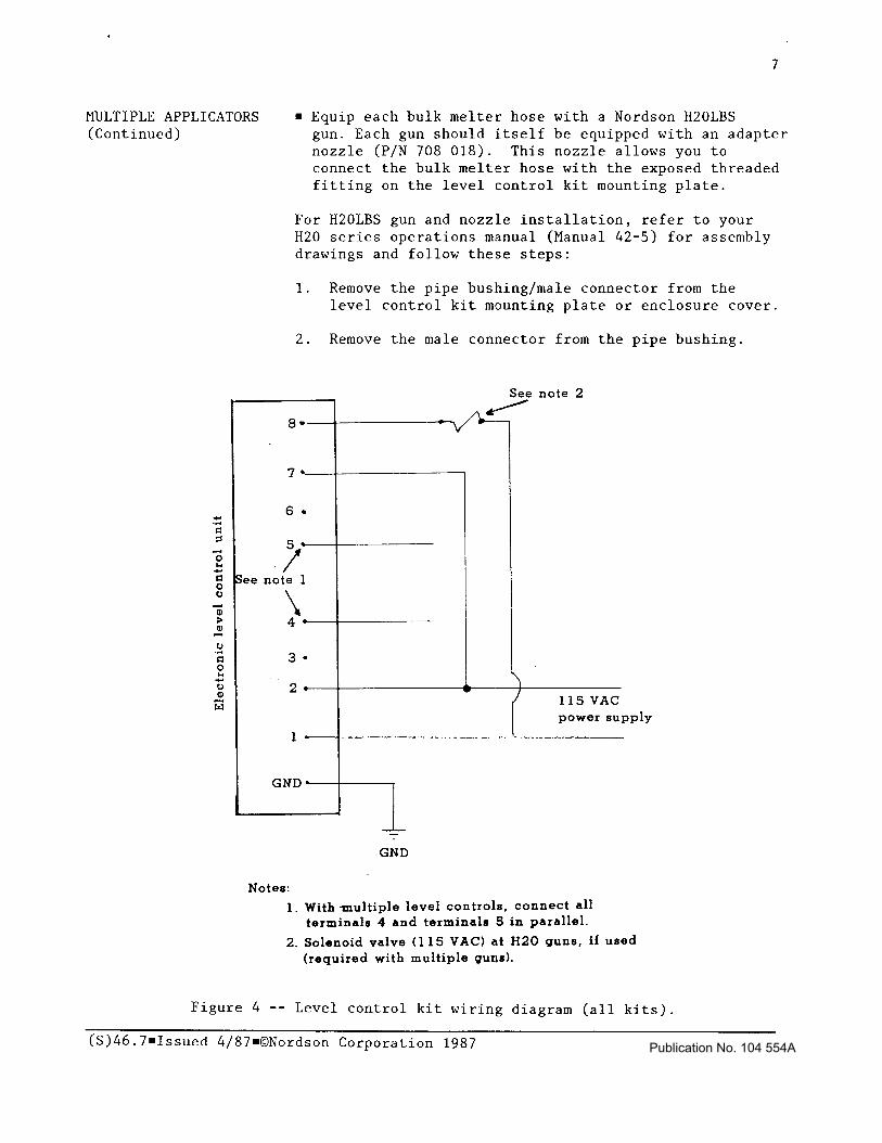
MULTIPLE APPLICATORS When using more than one applicator with a single bulk All Kits melter:
. Wire all control units in parallel to the bulk melter (do not wire one control unit to another).
(S)46=7Qssued 4/87@Nordson Corporation 1987 Publication No. 104 554A
7
MULTIPLE APPLICATORS n Equip each bulk melter hose with a Nordson H20LBS (Continued) gun. Each gun should itself be equipped with an adapter
nozzle (P/N 708 018). This nozzle allows you to connect the bulk melter hose with the exposed threaded fitting on the level control kit mounting plate.
For H20LBS gun and nozzle installation, refer to your H20 series operations m,anual (Manual 42-5) for assembly drawings and follow these steps:
1. Remove the pipe bushing/male connector from the level control kit mcounting plate or enclosure cover.
2. Remove the male connector from the pipe bushing.
See note 2
6 .
5*
-/ ee note 1
GND --l-T
1 - GND
Notes:
1. With multiple level controls, connect all
terminals 4 and terminals 5 in parallel.
2. Solenoid valve (115 VAC) at H20 guns, if used (required with multiple guns).
Figure 4 -- Level control kit wiring diagram (all kits).
(S)46.7mIssued 4/87WNordson Corporation 1987 Publication No. 104 554A

8
MULTIPLE APPLICATORS 3. Invert the pipe bushing, then reinstall it with (Continued) the fixed nut on the bushing above the mounting
plate and the jam nut below the mounting plate.
4. Use the H20LBS retaining nut to secure the adapter nozzle (P/N 708 018) to the gun.
5. Install the free end of the adapter nozzle inside the pipe bushing.
6. Install a 115 VAC solenoid valve on each H20LBS gun. The solenoid actuates the gun and must be wired in line between control unit terminals #l
and #8. Then install a jumper wire between control unit terminals #2 and #7.
LEVEL CALIBRATION 1. With the control unit terminal block exposed and All Kits all wiring connections completed, locate the:
n Operate point potentiometer (bronze-colored hex head screw)
n Differential adjust potentiometer (yellow plastic slot screw)
. Brown capacitor (Iextends above the top of the control unit.
. Jumper bar. Operate Point Potentiometer
Jumper Bar
Figure 5 -- Jumper bar and operate point potentiometer (differential adjust potentiometer not shown).
(S)46.7mIssued 4/87@Nordson Corporation 1987 Publication No. 104 554A

9
LEVEL CALIBRATION All Kits (Continued)
2.
3.
4.
5.
6.
7.
8.
9<
Confirm that the jumper bar is positioned for "High Level Fail Safe" (HLFS) operation. The jumper bar should not be located under the slot-head screw labeled "L".
Loosen the two slot-head screws that secure the capacitor to the terminal block, then remove the capacitor.
Turn the operate point potentiometer counterclock- wise until it stops.
NOTE: Do not force this potentiometer beyond its stop point. Damage to the unit may result.
Turn the differential potentiometer fully counter- clockwise. This signals the end of the OFF range.
Install and activate electrical power to the bulk melter, hot melt applicator unit(s) and level control unit.
a WARNING: This equipment contains energized
4 electrical components with potentials that could be fatal. Only qualified personnel should operate this equipment.
Fill the applicator tank to within one inch (1") of the top of the tank.
A WARNING: Wear safety glasses, safety gloves (P/N 902 514) and protective clothing to prevent injury from hot applicator parts, splashed hot melt adhesive material and hot gun surfaces.
NOTE: Be careful to keep hot melt material from overflowing when manually filling the tank. Overflowing the tank could create a fire hazard.
Raise the level control probe from the tank until only the bottom is still immersed in hot melt material.
Turn the operate point potentiometer clockwise until the red LED on the control unit lights.
(S)46.7mIssued 4/87+Nordson Corporation 1987 Publication No. 104 554A

10
LEVEL CALIBRATION All Kits (Continued)
10. Turn the differential adjust potentiometer fully clockwise.
NOTE: This is the LOW level set point. The bulk melter will activate when the level of hot melt material in the applicator tank reaches this point on the level control probe.
11. Fully insert the level control probe into the tank and secure it to its connection.
12. Turn the differential adjust potentiometer counter- clockwise until the red LED lights again.
NOTE: This is the HIGH level set point. The bulk melter will deactivate when hot melt material in the applicator tank reaches this point on the level control probe.
13. The bulk melter, hot melt applicator unit(s) and level control are now ready for operation.
(8)46 7 . n Issued 4/87@Nordson Corporation 1987 Publication No. 104 554A