Manual: MLT Series Analyzer Hardware including …... Instruction Manual NGA 2000 Hardware Manual...
250
www.EmersonProcess.com Instruction Manual NGA 2000 Hardware Manual for MLT or CAT 200 Analyzer and MLT or CAT 200 Analyzer Module (combined with NGA 2000 Platform, MLT, CAT 200 or TFID Analyzer) 11 th Edition 04/2008 Instruction Manual 90002929 04/2008
Transcript of Manual: MLT Series Analyzer Hardware including …... Instruction Manual NGA 2000 Hardware Manual...

www.EmersonProcess.com
Instruction ManualNGA 2000 Hardware Manual forMLT or CAT 200 Analyzer andMLT or CAT 200 Analyzer Module (combined withNGA 2000 Platform, MLT, CAT 200 or TFID Analyzer)11th Edition 04/2008
Instruction Manual9000292904/2008

NGA 2000 MLT Hardware Instruction Manual90002929
04/2008
Emerson Process ManagementGmbH & Co. OHGIndustriestrasse 1D-63594 HasselrothGermanyT +49 (0) 6055 884-0F +49 (0) 6055 884-209Internet: www.EmersonProcess.com
ESSENTIAL INSTRUCTIONSREAD THIS PAGE BEFORE PROCEEDING!
Emerson Process Management (Rosemount Analytical) designs, manufactures and testsits products to meet many national and international standards. Because these instrumentsare sophisticated technical products, you MUST properly install, use, and maintainthem to ensure they continue to operate within their normal specifications. The followinginstructions MUST be adhered to and integrated into your safety program when installing,using and maintaining Emerson Process Management (Rosemount Analytical) products.Failure to follow the proper instructions may cause any one of the following situations tooccur: Loss of life; personal injury; property damage; damage to this instrument; and warrantyinvalidation.
• Read all instructions prior to installing, operating, and servicing the product.
• If you do not understand any of the instructions, contact your Emerson ProcessManagement (Rosemount Analytical) representative for clarification.
• Follow all warnings, cautions, and instructions marked on and supplied with the product.
• Inform and educate your personnel in the proper installation, operation, andmaintenance of the product.
• Install your equipment as specified in the Installation Instructions of the appropriateInstruction Manual and per applicable local and national codes. Connect all productsto the proper electrical and pressure sources.
• To ensure proper performance, use qualified personnel to install, operate, update, program,and maintain the product.
• When replacement parts are required, ensure that qualified people use replacement partsspecified by Emerson Process Management (Rosemount Analytical). Unauthorized partsand procedures can affect the product’s performance, place the safe operation of yourprocess at risk, and VOID YOUR WARRANTY. Look-alike substitutions may result in fire,electrical hazards, or improper operation.
• Ensure that all equipment doors are closed and protective covers are in place, exceptwhen maintenance is being performed by qualified persons, to prevent electricalshock and personal injury.
The information contained in this document is subject to change without notice. Misprintsreserved.
1st Edition 02/1997 2nd Edition 03/1997 3rd Edition 09/1997 4th Edition 04/19985th Edition 07/1999 6th Edition 10/1999 7th Edition 04/2003 8th Edition 08/20049th Edition 07/2006 10th Edition 01/2007 11th Edition 04/2008 © 1997-2008 by Emerson Process Management

NGA 2000 MLT HardwareCONTENTS
IEmerson Process Management GmbH & Co. OHG
Instruction Manual90002929
01/2007
Table of ContentsPREAMBEL ....................................................................................S - 1
DEFINITIONS.................................................................................. S - 1
SAFETY INSTRUCTIONS ............................................................. S - 2Operating and maintaining this apparatus................................... S - 3Intended use statement ................................................................. S - 4Safety summary.............................................................................. S - 4Authorized personnel..................................................................... S - 4Gases and Gas Conditioning (Sample Handling) ........................ S - 6Power Supply.................................................................................. S - 7Instruments with External Power Supply Unit ................................... S - 7Instruments with Internal Power Supply Unit .................................... S - 7General operating instructions ..................................................... S - 9Additional hints for UV measurement ........................................ S - 10Magnetically Operated Front Panel ............................................ S - 11Electrostatic Discharge................................................................ S - 12
PREFACE........................................................................................ P - 1a) Analyzer versions ......................................................................... P - 1
Standard General Purpose Applications........................................ P - 1 b) Analyzer versions
Installation in Hazardous Areas ..................................................... P - 2c) Analyzer System Architecture ....................................................... P - 4
DESCRIPTION
1. Technical Description .................................................................... 1 - 11.1 Standard General Purpose Applications .......................................... 1 - 11.2 Installation in Hazardous Areas ........................................................ 1 - 11.3 Operating Front Panel ...................................................................... 1 - 21.3.1 Standard Version ........................................................................... 1 - 21.3.2 Magnetically Operated Touch Panel .............................................. 1 - 31.3.2.1 Magnetic Touch Panel Elements.................................................. 1 - 31.3.2.2 Accessories .................................................................................. 1 - 41.3.2.3 Operating the Touch Panel .......................................................... 1 - 4

NGA 2000 MLT HardwareCONTENTS
II Emerson Process Management GmbH & Co. OHG
Instruction Manual90002929
01/2007
1.4 MLT 1 ............................................................................................... 1 - 61.4.1 MLT 1 1/2 19" housing ................................................................... 1 - 61.4.2 MLT 1 ULCO ................................................................................ 1 - 111.4.3 MLT 1 Housing for platform mounting .......................................... 1 - 131.5 MLT 2 (Field Housing) .................................................................... 1 - 171.6 MLT 3 ............................................................................................. 1 - 211.6.1 MLT 3 (Gas purity measurement) ................................................. 1 - 231.6.2 MLT 3HT (high temperature measurement).......................................1 - 241.7 MLT 4 ............................................................................................. 1 - 261.8 CAT 200 ......................................................................................... 1 - 281.9 Internal Gas Paths .......................................................................... 1 - 321.9.1 Gas Path Material ........................................................................ 1 - 321.9.2 Gas Path Layout (internal tubing)................................................. 1 - 331.9.3 MLT 3 (gas purity measurement) ................................................. 1 - 341.10 Printed Circuit Boards .................................................................... 1 - 361.10.1 ICB (Inter-Connection Board) ....................................................... 1 - 371.10.2 PSV/PIC Combination ................................................................. 1 - 371.10.3 DSP (alternitavely to PSV/PIC Combination) .............................. 1 - 371.10.4 PIC (Physics Interface Card) ........................................................ 1 - 381.10.5 Digital Signal Processing Card (DSP) ......................................... 1 - 391.10.6 ACU ............................................................................................. 1 - 401.10.7 SIO (Standard Inputs-/Outputs) .................................................... 1 - 411.10.8 DIO (Digital In-/Outputs) ............................................................... 1 - 421.11 Network Termination ...................................................................... 1 - 431.12 Specifications at the Nameplate Label ........................................... 1 - 441.13 MLT 2HT (high temperature measurement)...................... ................ 1 - 46
2. Measuring Principle ....................................................................... 2 - 12.1 IR Measurement ............................................................................... 2 - 12.1.1 Opto - Pneumatic Measuring Principle........................................... 2 - 32.1.2 Interference Filter Correlation (IFC Principle) ................................ 2 - 42.2 UV Measurement.............................................................................. 2 - 62.3 Oxygen Measurement ...................................................................... 2 - 72.3.1 Paramagnetic Measurement (PO
2)................................................. 2 - 7
2.3.2 Electrochemical Measurement (EO2) ........................................... 2 - 11
2.3.3 Trace Electrochemical Measurement (TEO2) ............................... 2 - 13
2.4 Thermal Conductivity ..................................................................... 2 - 152.4.1 Sensor Design ............................................................................. 2 - 152.4.2 Analysis Cell ................................................................................ 2 - 152.4.3 Measurement Method .................................................................. 2 - 16
3. (vacant)4. (vacant)

NGA 2000 MLT HardwareCONTENTS
IIIEmerson Process Management GmbH & Co. OHG
Instruction Manual90002929
07/2006
OPERATION (START-UP)
5. Installation .................................................................................... 5 - 15.1 General ........................................................................................... 5 - 15.1.1 Transfer Safety Lock of MLT 1/ULCO or MLT 2 .......................... 5 - 35.2 Gas Conditioning (Sample Handling) ............................................. 5 - 45.2.1 Fine Dust Filter (Option MLT 3) ................................................... 5 - 55.2.2 Gas Sampling Pump (Option MLT 3) ........................................... 5 - 55.2.3 Pressure Sensor (Option) ............................................................ 5 - 55.2.4 Gas Flow...................................................................................... 5 - 55.3 Gas Connections ............................................................................ 5 - 65.3.1 Internal Solenoid Valve Block (Option for MLT 1/CAT 200) ......... 5 - 85.3.2 Purge Gas Connections ............................................................... 5 - 85.4 Analyzer Specific Instructions......................................................... 5 - 95.4.1 MLT 1........................................................................................... 5 - 95.4.1.1 MLT 1, platform mounting only ................................................... 5 - 95.4.1.2 MLT 1, external installation and 1/2-19" Housing ....................... 5 - 105.4.2 MLT 2 (Field Housing) ................................................................. 5 - 135.4.2.1 Wall Mounting ............................................................................ 5 - 135.4.2.2 Electrical Connections ................................................................ 5 - 15
a) Mains Supply ......................................................................... 5 - 16b) optional Data Lines ................................................................ 5 - 16c) Cable Gland Assembly Instruction for Shielded Cables ......... 5 - 19d) Gas Connections ................................................................... 5 - 20
5.4.3 MLT 3........................................................................................... 5 - 215.4.3.1 MLT 3 for gas purity measurement ............................................ 5 - 22
a) Instrument with manual 4/2-way-valve ................................... 5 - 22b) Instrument with solenoid valve block...................................... 5 - 23c) Instrument with quick shutoff connector ................................. 5 - 23
5.4.4 MLT 4........................................................................................... 5 - 245.4.5 CAT 200....................................................................................... 5 - 265.4.5.1 Wall Mounting ............................................................................ 5 - 275.4.5.2 Electrical Connections ................................................................ 5 - 285.4.5.3 Gas Connections........................................................................ 5 - 315.5 Wiring Signal Terminals.................................................................. 5 - 325.5.1 Electrical Connections in General ................................................ 5 - 325.5.2 Wiring Inductive Loads................................................................. 5 - 345.5.3 Driving Multiple Loads.................................................................. 5 - 355.5.4 Driving High Current Loads.......................................................... 5 - 36

NGA 2000 MLT HardwareCONTENTS
IV Emerson Process Management GmbH & Co. OHG
Instruction Manual90002929
07/2006
6. Switching On .................................................................................. 6 - 1
7. Measurement / Calibration / Switching Off .................................. 7 - 17.1 Measurement ................................................................................... 7 - 17.2 Calibration ........................................................................................ 7 - 27.2.1 Test Gases .................................................................................... 7 - 37.2.1.1 Zero Gas ...................................................................................... 7 - 37.2.1.2 Span Gas ..................................................................................... 7 - 37.3 Switching Off .................................................................................... 7 - 4
8.- (vacant)9.
TROUBLESHOOTING
10. Troubleshooting ........................................................................... 10 - 110.1 Instrument has no function (LCD display is dark) ........................... 10 - 110.2 No / Incorrect Measurement Screen............................................... 10 - 210.3 Display Messages .......................................................................... 10 - 310.3.1 Chopper Fail ................................................................................ 10 - 310.3.2 Raw Signal Too High / Low.......................................................... 10 - 310.3.3 Detector signal communication failed .......................................... 10 - 410.3.4 Light source ................................................................................. 10 - 410.3.5 Detector ....................................................................................... 10 - 410.3.6 Heater Unit Regulation................................................................. 10 - 510.3.7 Temperature Measurement ......................................................... 10 - 510.3.8 Invalid Pressure Measurement .................................................... 10 - 510.3.9 External Input ............................................................................... 10 - 610.4 No or incorrect Analog Outputs / Digital I/O's ................................. 10 - 610.5 Calibration not possible .................................................................. 10 - 710.6 Fluctuating or erroneous display .................................................... 10 - 810.7 Response time too long (t90 time)................................................. 10 - 9
NGA 2000 MLT HardwareCONTENTS
VEmerson Process Management GmbH & Co. OHG
Instruction Manual90002929
07/2006
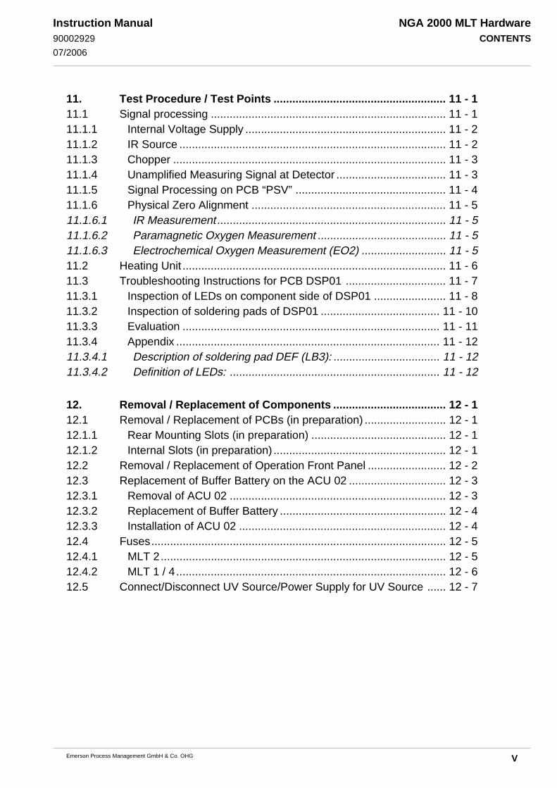
11. Test Procedure / Test Points ....................................................... 11 - 111.1 Signal processing ........................................................................... 11 - 111.1.1 Internal Voltage Supply ................................................................ 11 - 211.1.2 IR Source ..................................................................................... 11 - 211.1.3 Chopper ....................................................................................... 11 - 311.1.4 Unamplified Measuring Signal at Detector ................................... 11 - 311.1.5 Signal Processing on PCB “PSV” ................................................ 11 - 411.1.6 Physical Zero Alignment .............................................................. 11 - 511.1.6.1 IR Measurement ......................................................................... 11 - 511.1.6.2 Paramagnetic Oxygen Measurement ......................................... 11 - 511.1.6.3 Electrochemical Oxygen Measurement (EO2) ........................... 11 - 511.2 Heating Unit .................................................................................... 11 - 611.3 Troubleshooting Instructions for PCB DSP01 ................................ 11 - 711.3.1 Inspection of LEDs on component side of DSP01 ....................... 11 - 811.3.2 Inspection of soldering pads of DSP01 ...................................... 11 - 1011.3.3 Evaluation .................................................................................. 11 - 1111.3.4 Appendix .................................................................................... 11 - 1211.3.4.1 Description of soldering pad DEF (LB3): .................................. 11 - 1211.3.4.2 Definition of LEDs: ................................................................... 11 - 12
12. Removal / Replacement of Components .................................... 12 - 112.1 Removal / Replacement of PCBs (in preparation) .......................... 12 - 112.1.1 Rear Mounting Slots (in preparation) ........................................... 12 - 112.1.2 Internal Slots (in preparation) ....................................................... 12 - 112.2 Removal / Replacement of Operation Front Panel ......................... 12 - 212.3 Replacement of Buffer Battery on the ACU 02 ............................... 12 - 312.3.1 Removal of ACU 02 ..................................................................... 12 - 312.3.2 Replacement of Buffer Battery ..................................................... 12 - 412.3.3 Installation of ACU 02 .................................................................. 12 - 412.4 Fuses.............................................................................................. 12 - 512.4.1 MLT 2........................................................................................... 12 - 512.4.2 MLT 1 / 4 ...................................................................................... 12 - 612.5 Connect/Disconnect UV Source/Power Supply for UV Source ...... 12 - 7

NGA 2000 MLT HardwareCONTENTS
VI Emerson Process Management GmbH & Co. OHG
Instruction Manual90002929
07/2006
MAINTENANCE ............................................................................. 13 - 1
14. Leak Testing ................................................................................. 14 - 1
15. Opening the Housing ................................................................... 15 - 115.1 MLT 1 ............................................................................................. 15 - 215.1.1 MLT 1 (Platform housing) ............................................................... 15 - 215.1.1.1 Housing Cover ........................................................................... 15 - 215.1.1.2 Front Panel ................................................................................. 15 - 315.1.2 MLT 1 (1/2 19" housing) .............................................................. 15 - 415.1.2.1 Housing Cover ........................................................................... 15 - 415.1.2.2 Front Panel ................................................................................. 15 - 515.2 MLT 2 (Field Housing) .................................................................... 15 - 615.3 MLT 3/4 (1/1 19" housing) .............................................................. 15 - 815.3.1 Housing Cover ............................................................................. 15 - 815.3.2 Front Panel (MLT 4 / MLT 3 standard version) ............................ 15 - 815.3.3 Front Panel (MLT 3 gas purity measurement) ............................. 15 - 915.3.3.1 Operation Front Panel ................................................................ 15 - 915.3.3.2 Left Front Panel .......................................................................... 15 - 915.4 CAT 200 ....................................................................................... 15 - 1015.4.1 Junction Box .............................................................................. 15 - 1215.4.2 Dome ......................................................................................... 15 - 1315.4.3 Magnetically Operated Front Panel ........................................... 15 - 1615.4.3.1 Sliding the Analyzer into Position ............................................. 15 - 1615.4.3.2 Fixing the Analyzer ................................................................... 15 - 1615.4.3.3 Completing the Adjustment ...................................................... 15 - 16
16. Fine Dust filter (MLT 3 Option) .................................................... 16 - 1
17. Replacement and Cleaning of Photometric Components ........ 17 - 117.1 Removal of the Photometer Assembly ........................................... 17 - 217.2 Light Source Replacement (IR) ...................................................... 17 - 317.3 Cleaning of Analysis Cells and Windows ....................................... 17 - 417.3.1 Removal of Analysis Cells ........................................................... 17 - 417.3.2 Cleaning ....................................................................................... 17 - 517.3.3 Reinstalling of Analysis Cells ....................................................... 17 - 617.4 Reinstalling of the Photometer Assembly ....................................... 17 - 717.5 Physical Zeroing ............................................................................. 17 - 8

NGA 2000 MLT HardwareCONTENTS
VIIEmerson Process Management GmbH & Co. OHG
Instruction Manual90002929
07/2006
18. Check / Replacement of electrochemical Oxygen Sensor ........ 18 - 118.1 EO2-Sensor .................................................................................... 18 - 218.2 Check of the EO2-Sensor ............................................................... 18 - 318.3 Replacement of the EO2-Sensor .................................................... 18 - 418.3.1 Removal of the EO2-Sensor ......................................................... 18 - 418.3.2 Replacing the EO2-Sensor ........................................................... 18 - 518.3.3 Reinstalling of the EO2-Sensor .................................................... 18 - 518.3.4 Basic conditions for the EO2-Sensor ............................................ 18 - 618.4 TEO2-Sensor .................................................................................. 18 - 7
19. Cleaning of Housing Outside ...................................................... 19 - 1
TECHNICAL DATA ........................................................................ 20 - 120.1 Housing .......................................................................................... 20 - 120.2 Options ........................................................................................... 20 - 220.3 General Specifications ................................................................... 20 - 320.4 Voltage supply .............................................................................. 20 - 1120.4.1 Analyzers...................................................................................... 20 - 1120.4.1.1 MLT 1/4 .................................................................................... 20 - 1120.4.1.2 MLT 2/3 .................................................................................... 20 - 1120.4.1.3 CAT 200 ................................................................................... 20 - 1120.4.1.4 Electrical Safety ....................................................................... 20 - 1120.4.2 Power Supplies .......................................................................... 20 - 1220.4.2.1 UPS 01 T (Universal Power Supply) ........................................ 20 - 1220.4.2.2 External 5A Power Supply Unit for DIN Rail Installation........... 20 - 1420.4.2.3 External 10A Power Supply Unit for DIN Rail Installation......... 20 - 1620.4.2.4 Tabletop Power Supply Units ................................................... 20 - 18

NGA 2000 MLT HardwareCONTENTS
VIII Emerson Process Management GmbH & Co. OHG
Instruction Manual90002929
07/2006
SUPPLEMENT
21. Pin Assignments ........................................................................ 21 - 121.1 24 V dc Input (MLT 1/4) ................................................................ 21 - 121.2 230/120 V ac Input (MLT 3) .......................................................... 21 - 121.3 Option SIO (Standard I/O) ............................................................ 21 - 221.3.1 Analog Signal Outputs ............................................................... 21 - 221.3.2 Relay Outputs / Serial Interfaces ............................................... 21 - 221.4 Option DIO (Digitale I/O) .............................................................. 21 - 321.5 Terminal Assignment of CAT 200................................................. 21 - 421.6 CAT 200 Increased Safety Box - Label Schematic ........................21 - 7
22. Calculation of Water Content from Dew-point toVol. -% or g/Nm³.......................................................................... 22 - 1

NGA 2000 MLT HardwareCONTENTS
IXEmerson Process Management GmbH & Co. OHG
Instruction Manual90002929
07/2006
LIST OF FIGURES
Fig. Title Page
Fig. P-1: Analyzer Nameplate Label (example) .............................................................................P - 3Fig. P-2: From separate analyzers to analyzer system .................................................................P - 4Fig. P-3: Example of NGA-cabling ................................................................................................. P - 5Fig. P-4: Example/possibilities of NGA analyzer system ............................................................... P - 6
Fig. 1-1: Operation front panel, Front view .................................................................................... 1 - 2Fig. 1-2: Magnetically Operated Touch Panel, Front view ............................................................ 1 - 3Fig. 1-3a: Magnetic actuator ........................................................................................................... 1 - 5Fig. 1-3b: Magnetic actuator, view at magnets................................................................................ 1 - 5Fig. 1-4a: Symbols showing actuator alignment ............................................................................. 1 - 4Fig. 1-4b: Horizontally aligned, activating F4 .................................................................................. 1 - 5Fig. 1-4c: Vertically aligned, activating F5....................................................................................... 1 - 5Fig. 1-5: Actuator stored when not in use ..................................................................................... 1 - 4Fig. 1-6: MLT analyzer, Front view ................................................................................................ 1 - 6Fig. 1-7: MLT 1, Front panel, Rear view ........................................................................................ 1 - 7Fig. 1-8: MLT 1, Rear panel (standard) ......................................................................................... 1 - 7Fig. 1-9: MLT 1, Rack/Table-top Housing, Top view (with electrochemical O
2 Sensor) ................ 1 - 8
Fig. 1-10: MLT 1, Rack/Table-top Housing, Top viewA(with paramagnetic O2 Sensor) .................. 1 - 9
Fig. 1-11: MLT 1, Rack/Table-top Housing extended, Top view (with paramagnetic O2 Sensor) . 1 - 10
Fig. 1-12: MLT 1 ULCO, Rack/Table-top Housing, Top view ........................................................ 1 - 12Fig. 1-13: MLT 1 Analyzer module (Platform mounting), Front panel, Front view ......................... 1 - 13Fig. 1-14: MLT 1, Platform mounting, Top view (with electrochemical O
2 Sensor) ....................... 1 - 14
Fig. 1-15: MLT 1, Platform mounting, Top view (with paramagnetical O2 Sensor) ........................ 1 - 15
Fig. 1-16: MLT 1, Platform mounting extended, Top view (with paramagnetic O2 Sensor) ........... 1 - 16
Fig. 1-17a: Front view MLT 2 (Standard housing/Standard operation front panel) ......................... 1 - 19Fig. 1-17b: Front view MLT 2 (Dual compartment housing/Standard operation front panel) ........... 1 - 19Fig. 1-18a: MLT 2, Inside view (drawing without front panel) .......................................................... 1 - 20Fig. 1-18b: MLT 2, Photometer sliding carriage, Top view .............................................................. 1 - 20Fig. 1-19: MLT 3 (standard) (1/1 19" housing), front view ............................................................ 1 - 21Fig. 1-20: MLT 3 (standard version), Rear view ........................................................................... 1 - 21Fig. 1-21: MLT 3 (standard version), Top view ............................................................................. 1 - 22Fig. 1-22: MLT 3 (gas purity measurement), front view................................................................. 1 - 23Fig. 1-23: MLT 3 (gas purity measurement), Rear view ................................................................ 1 - 24Fig. 1-24: MLT 3 (gas purity measurement), Top view.................................................................. 1 - 25Fig. 1-25: MLT 4 (1/1 19" housing), front view .............................................................................. 1 - 26Fig. 1-26: MLT 4, Rear view .......................................................................................................... 1 - 26Fig. 1-27: MLT 4, Rack/Table-top Housing, Top view ................................................................... 1 - 27Fig. 1-28: CAT 200, Exterior view ................................................................................................. 1 - 30Fig. 1-29: CAT 200 (Dome and extender housing removed) ........................................................ 1 - 31Fig. 1-30a: MLT 3 (gas purity measurement), gas path layout .................................................................
(3 measuring channels with solenoid valve block option) ............................................. 1 - 34Fig. 1-30b: MLT 3 (gas purity measurement), gas path layout .................................................................
(3 measuring channels with valve block option and quick shuttoff connector option) ... 1 - 35Fig. 1-30c: MLT 3 (gas purity measurement), gas path layout .................................................................
(2 measuring channels with manual 4/2-way-valve option) .......................................... 1 - 35Fig. 1-31a: Cardcage MLT 1/3/4, Top View .................................................................................... 1 - 36Fig. 1-31b: PCB arrangement MLT 2 [Inside view, detail (without front panel)] .............................. 1 - 37
LIST OF FIGURES

NGA 2000 MLT HardwareCONTENTS
X Emerson Process Management GmbH & Co. OHG
Instruction Manual90002929
07/2006
Fig. Title Page
Fig. 1-32: Plug pin assignment PCB PIC ...................................................................................... 1 - 38Fig. 1-33: Plug pin assignment PCB DSP ..................................................................................... 1 - 39Fig. 1-34: Function blocks of SIO-PCB ......................................................................................... 1 - 41Fig. 1-35: SIO-PCB with extension cards ...................................................................................... 1 - 42Fig. 1-36: RJ 45 network termination connector ........................................................................... 1 - 43Fig. 1-37: Network termination (examples) ................................................................................... 1 - 43Fig. 1-38: Analyzer Nameplate Label (example) ........................................................................... 1 - 44
Fig. 2-1: Measuring Principle for NDIR / UV Measurement ........................................................... 2 - 2Fig. 2-2: Principle Design of Gas Detector .................................................................................... 2 - 3Fig. 2-3: Absorption Bands of Sample Gases and Transmittance of the .............................................
Interference Filters used ................................................................................................. 2 - 5Fig. 2-4: Principle Construction of paramagnetic Analysis Cell ..................................................... 2 - 8Fig. 2-5: Structure of electrochemical Oxygen Sensor ................................................................ 2 - 11Fig. 2-6: Reaction of galvanic cell ............................................................................................... 2 - 12Fig. 2-7: Structure of electrochemical Trace Oxygen Sensor ...................................................... 2 - 13Fig. 2-8: Sensor block (thermal conductivity detector TCD) ........................................................ 2 - 15Fig. 2-9: Measuring principle Thermal Conductivity Sensor (Wheatstone bridge) ...................... 2 - 16
Fig. 5-1a: Transfer safety lock MLT-ULCO (housing side view, detail sketch) ................................ 5 - 3Fig. 5-1c: MLT 2, Photometer safety lock ....................................................................................... 5 - 3Fig. 5-1b: MLT 1, Rear panel (holder for safety lock) ...................................................................... 5 - 3Fig. 5-2: MLT, Bypass installation ................................................................................................. 5 - 7Fig. 5-3: MLT 1 analysis module (platform mounting), front panel, front view ............................... 5 - 9Fig. 5-4: MLT 1, standard gas connections ................................................................................. 5 - 11Fig. 5-5: MLT 1, gas connections with solenoid valve option ...................................................... 5 - 12Fig. 5-6a: Dimensional sketch / Drill drawing MLT 2 Standard version ......................................... 5 - 14Fig. 5-6b: Dimensional sketch / Drill drawing MLT 2 Dual housing version .................................. 5 - 14Fig. 5-8: MLT 2, Data line connections Inside view from front (detail, without front door) ........... 5 - 17Fig. 5-9: MLT 2, Connection data lines / mains line (inside view, left side panel) ....................... 5 - 18Fig. 5-10: Cable Gland Assembly Instruction for Shielded Cables ................................................ 5 - 19Fig. 5-11: Cable gland sealing plug / Cable gland allen screw sealing plug ................................. 5 - 19Fig. 5-12a: MLT 2, gas connections ................................................................................................ 5 - 20Fig. 5-12b: MLT 2, Gas fittings at analyzer’s bottom side ............................................................... 5 - 20Fig. 5-13: MLT 3 (standard version), gas connections and voltage supply ................................... 5 - 21Fig. 5-14: MLT 3 (gas purity measurement), Rear view ................................................................ 5 - 22Fig. 5-15: Solenoid valve block MLT 3 (gas purity measurement) (side view) .............................. 5 - 23Fig. 5-16: MLT 3 (gas purity measurement), front view................................................................. 5 - 23Fig. 5-17: MLT 4, Voltage supply .................................................................................................. 5 - 24Fig. 5-18: MLT 4, gas connections ................................................................................................ 5 - 25Fig. 5-19: Drill drawing CAT 200 [all dimensions in mm (Inch)] ..................................................... 5 - 27Fig. 5-20: CAT 200, Junction box, interior view............................................................................. 5 - 30Fig. 5-21: CAT 200, Analyzer’s bottom view at gas fittings ........................................................... 5 - 30Fig. 5-22: Shielded Signal Cable, shield connected at both ends ................................................. 5 - 32Fig. 5-23: Shielded Signal Cable, shield connected at one end .................................................... 5 - 32Fig. 5-24: Double-shielded Signal Cable, shields connected at both sides ................................... 5 - 33Fig. 5-25: Suppressor Diode for Inductive Loads .......................................................................... 5 - 34Fig. 5-26: ”Serial” Wiring ............................................................................................................... 5 - 35Fig. 5-27: Running Supply Lines "Parallel” .................................................................................... 5 - 35Fig. 5-28: Driving High Current Loads ........................................................................................... 5 - 36
LIST OF FIGURES
NGA 2000 MLT HardwareCONTENTS
XIEmerson Process Management GmbH & Co. OHG
Instruction Manual90002929
07/2006
Fig. Title Page
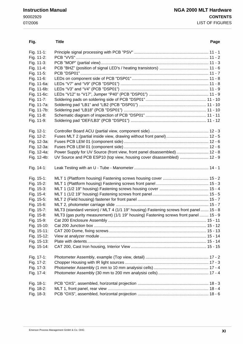
Fig. 11-1: Principle signal processing with PCB "PSV" ................................................................. 11 - 1Fig. 11-2: PCB "VVS" .................................................................................................................... 11 - 2Fig. 11-3: PCB "MOP” (partial view) .............................................................................................. 11 - 3Fig. 11-4: PCB "BHZ” (position of signal LED's / heating transistors) ........................................... 11 - 6Fig. 11-5: PCB "DSP01” ................................................................................................................ 11 - 7Fig. 11-6: LEDs on component side of PCB "DSP01” ................................................................... 11 - 8Fig. 11-6a: LEDs “V7” and “V9” (PCB "DSP01”) ............................................................................. 11 - 8Fig. 11-6b: LEDs “V3” and “V4” (PCB "DSP01”) ............................................................................. 11 - 9Fig. 11-6c: LEDs “V12” to “V17”, Jumper “P40” (PCB "DSP01”) .................................................... 11 - 9Fig. 11-7: Soldering pads on soldering side of PCB "DSP01” ..................................................... 11 - 10Fig. 11-7a: Soldering pad “LB1” and “LB2 (PCB "DSP01”) ........................................................... 11 - 10Fig. 11-7b: Soldering pad “LB18” (PCB "DSP01”) ........................................................................ 11 - 10Fig. 11-8: Schematic diagram of inspection of PCB "DSP01” ..................................................... 11 - 11Fig. 11-9: Soldering pad “DEF/LB3” (PCB "DSP01”) .................................................................. 11 - 12
Fig. 12-1: Controller Board ACU (partial view, component side) ................................................... 12 - 3Fig. 12-2: Fuses MLT 2 (partial inside view, drawing without front panel) ..................................... 12 - 5Fig. 12-3a: Fuses PCB LEM 01 (component side) .......................................................................... 12 - 6Fig. 12-3a: Fuses PCB LEM 01 (component side) .......................................................................... 12 - 6Fig. 12-4a: Power Supply for UV Source (front view, front panel disassembled) ............................ 12 - 8Fig. 12-4b: UV Source and PCB ESP10 (top view, housing cover disassembled) ......................... 12 - 9
Fig. 14-1: Leak Testing with an U - Tube - Manometer ................................................................. 14 - 1
Fig. 15-1: MLT 1 (Plattform housing) Fastening screws housing cover ........................................ 15 - 2Fig. 15-2: MLT 1 (Plattform housing) Fastening screws front panel .............................................. 15 - 3Fig. 15-3: MLT 1 (1/2 19" housing) Fastening screws housing cover ........................................... 15 - 4Fig. 15-4: MLT 1 (1/2 19" housing) Fastening screws front panel ................................................. 15 - 5Fig. 15-5: MLT 2 (Field housing) fastener for front panel .............................................................. 15 - 7Fig. 15-6: MLT 2, photometer carriage slide ................................................................................. 15 - 7Fig. 15-7: MLT3 (standard version) / MLT 4 (1/1 19" housing) Fastening screws front panel ....... 15 - 8Fig. 15-8: MLT3 (gas purity measurement) (1/1 19" housing) Fastening screws front panel ........ 15 - 9Fig. 15-9: Cat 200 Enclosure Assembly ...................................................................................... 15 - 11Fig. 15-10: Cat 200 Junction box .................................................................................................. 15 - 12Fig. 15-11: CAT 200 Dome, fixing screws ..................................................................................... 15 - 13Fig. 15-12: View at analyzer module ............................................................................................. 15 - 14Fig. 15-13: Plate with detents ........................................................................................................ 15 - 14Fig. 15-14: CAT 200, Cast Iron housing, Interior View .................................................................. 15 - 15
Fig. 17-1: Photometer Assembly, example (Top view, detail) ....................................................... 17 - 2Fig. 17-2: Chopper Housing with IR light sources ......................................................................... 17 - 3Fig. 17-3: Photometer Assembly (1 mm to 10 mm analysisi cells) ................................................ 17 - 4Fig. 17-4: Photometer Assembly (30 mm to 200 mm analysisi cells) ............................................ 17 - 4
Fig. 18-1: PCB “OXS”, assembled, horizontal projection .............................................................. 18 - 3Fig. 18-2: MLT 1, front panel, rear view ........................................................................................ 18 - 4Fig. 18-3: PCB “OXS”, assembled, horizontal projection .............................................................. 18 - 6
LIST OF FIGURES

NGA 2000 MLT HardwareCONTENTS
XII Emerson Process Management GmbH & Co. OHG
Instruction Manual90002929
07/2006
Fig. Title Page
Fig. 20- 1: Dimensional sketch MLT 1 [all dimensions in mm] ........................................................ 20 - 6Fig. 20- 2: Dimensional sketch / Drill drawing MLT 2 Standard version ........................................... 20 - 7Fig. 20- 3: Dimensional sketch / Drill drawing MLT 2 Dual housing version ..................................... 20 - 7Fig. 20- 4: Dimensional sketch MLT 2 for Ex Zone 2 in standard housing ....................................... 20 - 8Fig. 20- 5: Dimensional sketch MLT 2 for Ex Zone 1 in standard housing ....................................... 20 - 8Fig. 20- 6: Dimensional sketch MLT 2 for Ex Zones with “Z Purge” (MLT 2-NF) .......................................
or “Continuous purge” in standard housing ................................................................... 20 - 9Fig. 20- 7: Dimensional sketch MLT 3/4 ......................................................................................... 20 - 9Fig. 20- 8: Dimensional sketch / Drill drawing CAT 200 ............................................................... 20 - 10Fig. 20- 9: Dimensional sketch UPS 01 T (Universal Power Supply), table-top version .............. 20 - 13Fig.20-10a: IEC mains input plug (UPS 01 T) ................................................................................ 20 - 13Fig. 20-10b: 24 V DC output socket, Pin assignment (UPS 01 T) ................................................... 20 - 13Fig. 20-11: Power Supply SL5, Dimensions .................................................................................. 20 - 15Fig. 20-12: Power Supply SL 10, Dimensions ............................................................................... 20 - 17Fig. 20-13: 10 A Tabletop Power Supply, Dimensions .................................................................. 20 - 18
Fig. 21- 1: Pin assignments 24 V dc Input (MLT 1/4) ..................................................................... 21 - 1Fig. 21- 2: Pin assignments 230/120 V ac Input (MLT 3) ............................................................... 21 - 1Fig. 21- 3: Pin assignments Socket Analog Signal Outputs (Option SIO) ...................................... 21 - 2Fig. 21-4a: Pin assignments Socket Relay Outputs / RS 232 Serial Interface (Option SIO) ........... 21 - 2Fig. 21-4b: Pin assignments Socket Relay Outputs / RS 485 Serial Interface (Option SIO) ........... 21 - 2Fig. 21- 5: Pin assignments Socket Digital Inputs/Outputs (Option DIO) ........................................ 21 - 3
Fig. 21- 6: CAT 200, Junction box, interior view .............................................................................. 21 - 4
LIST OF TABLES
Table Title Page
Table P-1: Possibilities of NGA 2000 MLT I/O combinations ...........................................................P - 7
Table 1-1: Possible internal tubings (examples with 3 measuring channels) ................................... 1 - 33Table 2-1: Solvent Resistant Sensor: Approved solvents ................................................................. 2 - 9Table 2-2: Medium affected Materials within Paramagnetic Oxygen Sensor .................................... 2 - 9Table 2-3: Paramagnetic Oxygen Measurement, cross interference by accompanying gases ........ 2 - 10Table 5-1: CAT 200, Assignment of gas fittings ............................................................................. 5 - 30Table 11-1: Definition of LEDs/Default configuration of soldering pads (PCB "DSP01”) .................. 11 - 12Table 11-2: Definition of LEDs/Normal configuration of soldering pads (PCB "DSP01”) .................. 11 - 13Table 20-1: Specifications of MLT .................................................................................................... 20 - 4Table 20-2: Altered NDIR/VIS/UV-Specifications of MLT-ULCO compared to table 1 ...................... 20 - 5Table 21-1: CAT 200 Power Connections Terminal Assignments ..................................................... 21 - 5Table 21-2: CAT 200 Analog Signal Outputs Terminal Assignments (Option SIO) ............................ 21 - 5Table 21-3: CAT 200 Relay Outputs Terminal Assignments (Option SIO) ........................................ 21 - 5Table 21-4: CAT 200 Field Bus Terminal Assignments (Option) ....................................................... 21 - 5Table 21-5: CAT 200 RS 232 / RS 485 Serial Interface Terminal Assignments (Option SIO) ............ 21 - 6Table 21-6: CAT 200 Digital Inputs/Outputs Terminal Assignments (Option DIO) ............................. 21 - 6Table 21-7: CAT 200 Terminal Assignments - Bottom (Lower) Contacts ........................................... 21 - 8Table 21-8: CAT 200 Terminal Assignments - Top (Upper) Contacts ................................................ 21 - 8Table 22-2: Calculation of Water Content from Dew-point to Vol. -% or g/Nm³ .................................. 22 - 1
LIST OF FIGURES/LIST OF TABLES

NGA 2000 MLT HardwareSAFETY INSTRUCTIONS
S - 1Emerson Process Management GmbH & Co. OHG
Instruction Manual90002929
07/2006
Preambel
This instruction manual provides information about MLT and CAT200 series gas analyzers /analyzer
modules concerning subassemblies, functions, procedures, installation, operation and mainte-
nance.
This instruction manual covers several MLT and CAT200 series gas analyzers /analyzer modules
variations and therefore may describe configurations and/or options not part of your specific
analyzer.
Installation and operation of instruments intended to be installed and operated in HAZARDOUS
AREAS is NOT COVERED by this instruction manual, but part of the specific instruction manual
shipped together with such analyzers because of the special requirements for working in hazardous
environments!
Definitions
The following definitions apply to WARNINGS, CAUTIONS and NOTES found throughout this
publication.
Highlights an operation ormaintenance procedure,practice, condition, state-ment, etc.If not strictly observed, couldresult in injury, death, or long-term health hazards ofpersonnel.
Highlights an operation ormaintenance procedure,practice, condition, state-ment, etc.If not strictly observed, couldresult in damage to ordestruction of equipment, orloss of effectiveness.
PREAMBEL / DEFINITIONS
NOTEHighlights an essential operatingprocedure, condition or statement.

NGA 2000 MLT HardwareSAFETY INSTRUCTIONS
S - 2 Emerson Process Management GmbH & Co. OHG
Instruction Manual90002929
07/2006GENERAL
IMPORTANT
SAFETY INSTRUCTIONS
WIRING AND INSTALLATION OF THIS APPARATUSThe following safety instructions apply specifically to all EU member states. They should be
strictly adhered to in order to assure compliance with the Low Voltage Directive. Non-EUstates should also comply with the following unless superseded by local or NationalStandards.
1. Adequate earth connections should be made to all earthing points, internal and external,where provided.
2. After installation or troubleshooting, all safety covers and safety grounds must be replaced.The integrity of all earth terminals must be maintained at all times.
3. To ensure safe operation of this equipment, connection to the mains supply should onlybe made through a circuit breaker which will disconnect all circuits carrying conductorsduring a fault situation. The circuit breaker may also include a mechanically operatedisolating switch. Circuit breakers or switches must comply with a recognized standardsuch as IEC947. All wiring must conform with any local standards.
4. Where equipment or covers are marked with the symbol to the right,hazardous voltages are likely to be present beneath. These covers shouldonly be removed when power is removed from the equipment — and thenby trained service personnel only.
5. Where equipment or covers are marked with the symbol to the right, thereis a danger from hot surfaces beneath. These covers should only beremoved by trained service personnel when power is removed from theequipment. Certain surfaces may remain hot to the touch.
6. Where equipment or covers are marked with the symbol to the right, referto the Instruction Manual for instructions.
7. Further graphical symbols used in this product:
All graphical symbols used in this product are from one or more of the following standards:EN61010-1, IEC417, and ISO3864.
Explosion Hazard!
Harmful (to Health)!
Elektrostatic discharge (ESD)
Toxic!
Heavy Instrument!
Disconnect from Mains!

NGA 2000 MLT HardwareSAFETY INSTRUCTIONS
S - 3Emerson Process Management GmbH & Co. OHG
Instruction Manual90002929
07/2006 OPERATING AND MAINTAINING THIS APPARATUS
Operating and maintaining this apparatus
This instrument has left the factory in compliance with all applicable safety regulations.To maintain this operating condition, the user must strictly follow the instructions and considerthe warnings in this manual or provided on the instrument.
Before switching on the instrument, verify that the electrical supply voltage matches theinstrument´s operating voltage as set in the factory.
Any interruption in the instrument´s ground line, whether inside or outside the instrument, orremoval or interruption of its ground line connection, could result in hazardous operatingconditions. Intentionally interrupting the instrument´s protective ground is strictly prohibited.
Opening cover panels could expose voltage-carrying components. Connectors may also beunder voltage. The instrument must be disconnected from all electrical supplies beforeattempting any calibrations, maintenance operations, repairs or component replacementsrequiring opening of the instrument. Any calibrations, maintenance operations, or repairs thatneed the instrument to be opened while connected to electrical supplies should be subject toqualified technicians familiar with the hazards involved only!
Use only fuses of the correct type and current ratings as replacements. Using repaired fusesand short circuiting of fuse holders is prohibited.
Observe all applicable regulations when operating the instrument from an auto-transformeror variac.
Substances hazardous to health may emerge from the instrument‘s exhaust.Please pay attention to the safety of your operation personnel. Protective measures must betaken, if required.
NGA 2000 MLT HardwareSAFETY INSTRUCTIONS
S - 4 Emerson Process Management GmbH & Co. OHG
Instruction Manual90002929
07/2006INTENDED USE STATEMENT / SAFETY SUMMARY / AUTHORIZED PERSONNEL
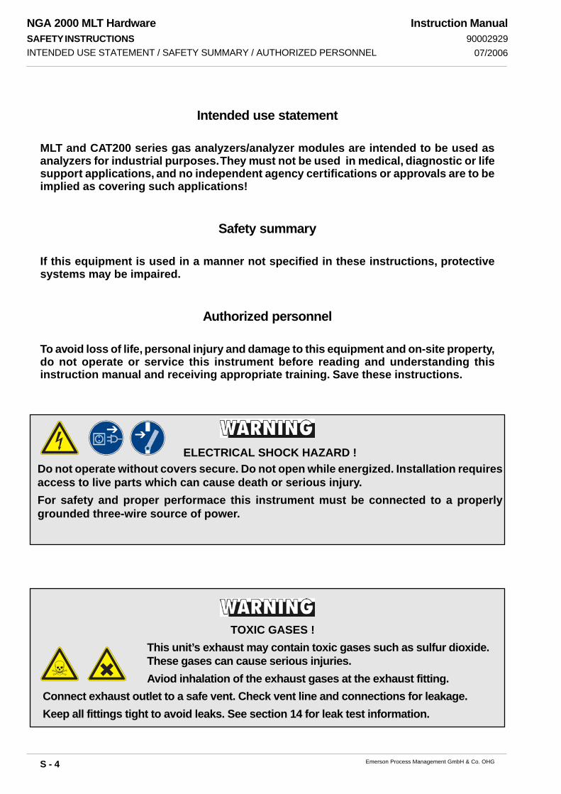
Intended use statement
MLT and CAT200 series gas analyzers/analyzer modules are intended to be used asanalyzers for industrial purposes. They must not be used in medical, diagnostic or lifesupport applications, and no independent agency certifications or approvals are to beimplied as covering such applications!
Safety summary
If this equipment is used in a manner not specified in these instructions, protectivesystems may be impaired.
Authorized personnel
To avoid loss of life, personal injury and damage to this equipment and on-site property,do not operate or service this instrument before reading and understanding thisinstruction manual and receiving appropriate training. Save these instructions.
ELECTRICAL SHOCK HAZARD !Do not operate without covers secure. Do not open while energized. Installation requiresaccess to live parts which can cause death or serious injury.For safety and proper performace this instrument must be connected to a properlygrounded three-wire source of power.
TOXIC GASES !This unit’s exhaust may contain toxic gases such as sulfur dioxide.These gases can cause serious injuries.Aviod inhalation of the exhaust gases at the exhaust fitting.
Connect exhaust outlet to a safe vent. Check vent line and connections for leakage.Keep all fittings tight to avoid leaks. See section 14 for leak test information.

NGA 2000 MLT HardwareSAFETY INSTRUCTIONS
S - 5Emerson Process Management GmbH & Co. OHG
Instruction Manual90002929
07/2006
EXPLOSION HAZARD !Do not operate nor install these instruments in hazardous areas withoutadditional measures!
MLT 2 and CAT 200 -- HEAVY INSTRUMENTS !The analyzer variations MLT 2 and CAT 200 intended to be wallmounted and/or outdoor installed weigh up to 35 kg resp. 70 kg, dependingon included options!Use two person and/or suitable tools for transportation and lifting theseinstruments!Take care to use anchors and bolts specified to be used for the weight ofthe units!Take care the wall or stand the unit is intended to be installed at is solidand stable to hold the units!
HIGH TEMPERATURES !While working at photometers and/or thermostated components inside theanalyzers hot components may be accessible!
The electrochemical O2-sensor contains electrolyte which is caustic andcan cause serious burns to skin. Do not ingest contents of sensor !
CAUSTIC !
Tampering with or unauthorized substitution of components may adversely affect thesafety of this instrument. Use only factory approved components for repair.Because of the danger of introducing additional hazards, do not perform any unauthorizedmodification to this instrument!
NGA 2000 MLT HardwareSAFETY INSTRUCTIONS
S - 6 Emerson Process Management GmbH & Co. OHG
Instruction Manual90002929
07/2006
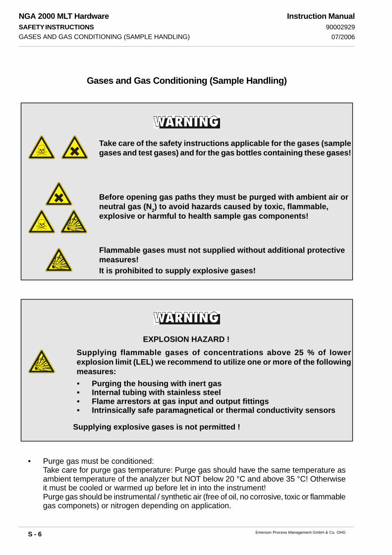
Gases and Gas Conditioning (Sample Handling)
GASES AND GAS CONDITIONING (SAMPLE HANDLING)
Supplying explosive gases is not permitted !
EXPLOSION HAZARD !Supplying flammable gases of concentrations above 25 % of lowerexplosion limit (LEL) we recommend to utilize one or more of the followingmeasures:• Purging the housing with inert gas• Internal tubing with stainless steel• Flame arrestors at gas input and output fittings• Intrinsically safe paramagnetical or thermal conductivity sensors
• Purge gas must be conditioned:Take care for purge gas temperature: Purge gas should have the same temperature asambient temperature of the analyzer but NOT below 20 °C and above 35 °C! Otherwiseit must be cooled or warmed up before let in into the instrument!Purge gas should be instrumental / synthetic air (free of oil, no corrosive, toxic or flammablegas componets) or nitrogen depending on application.
Take care of the safety instructions applicable for the gases (samplegases and test gases) and for the gas bottles containing these gases!
Before opening gas paths they must be purged with ambient air orneutral gas (N2) to avoid hazards caused by toxic, flammable,explosive or harmful to health sample gas components!
Flammable gases must not supplied without additional protectivemeasures!It is prohibited to supply explosive gases!
NGA 2000 MLT HardwareSAFETY INSTRUCTIONS
S - 7Emerson Process Management GmbH & Co. OHG
Instruction Manual90002929
07/2006 POWER SUPPLY
Power Supply
Instruments with External Power Supply Unit
Instruments with Internal Power Supply Unit
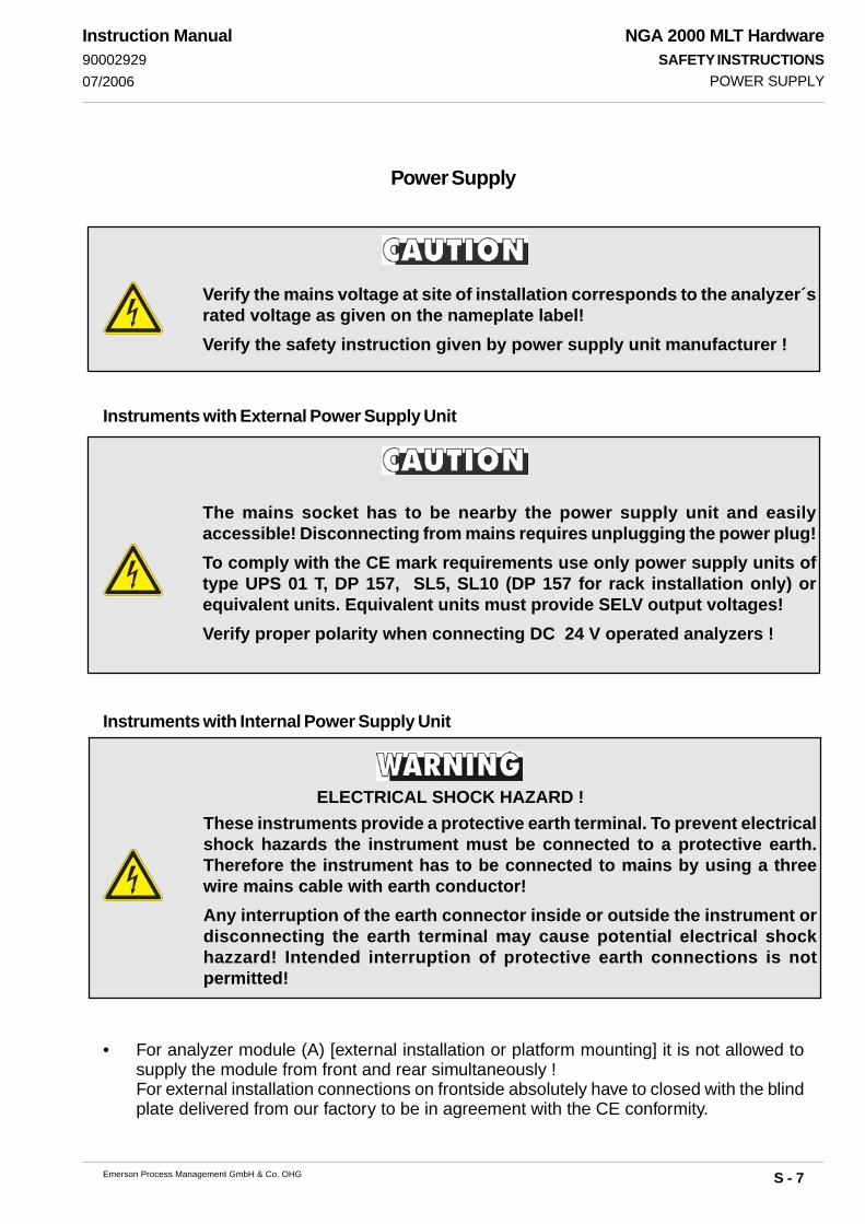
Verify the mains voltage at site of installation corresponds to the analyzer´srated voltage as given on the nameplate label!Verify the safety instruction given by power supply unit manufacturer !
The mains socket has to be nearby the power supply unit and easilyaccessible! Disconnecting from mains requires unplugging the power plug!To comply with the CE mark requirements use only power supply units oftype UPS 01 T, DP 157, SL5, SL10 (DP 157 for rack installation only) orequivalent units. Equivalent units must provide SELV output voltages!Verify proper polarity when connecting DC 24 V operated analyzers !
These instruments provide a protective earth terminal. To prevent electricalshock hazards the instrument must be connected to a protective earth.Therefore the instrument has to be connected to mains by using a threewire mains cable with earth conductor!Any interruption of the earth connector inside or outside the instrument ordisconnecting the earth terminal may cause potential electrical shockhazzard! Intended interruption of protective earth connections is notpermitted!
ELECTRICAL SHOCK HAZARD !
• For analyzer module (A) [external installation or platform mounting] it is not allowed tosupply the module from front and rear simultaneously !For external installation connections on frontside absolutely have to closed with the blindplate delivered from our factory to be in agreement with the CE conformity.
NGA 2000 MLT HardwareSAFETY INSTRUCTIONS
S - 8 Emerson Process Management GmbH & Co. OHG
Instruction Manual90002929
07/2006ADDITIONAL HINTS FOR MLT 2 AND CAT 200
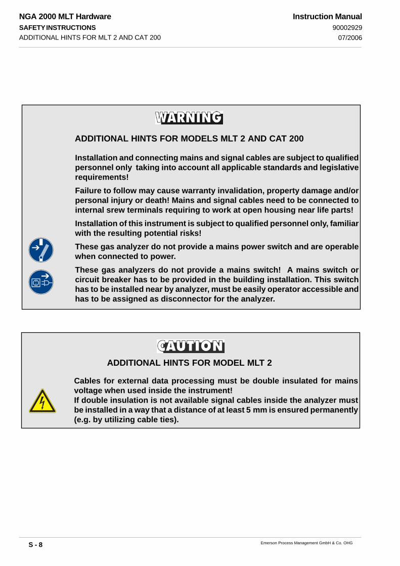
Installation and connecting mains and signal cables are subject to qualifiedpersonnel only taking into account all applicable standards and legislativerequirements!Failure to follow may cause warranty invalidation, property damage and/orpersonal injury or death! Mains and signal cables need to be connected tointernal srew terminals requiring to work at open housing near life parts!Installation of this instrument is subject to qualified personnel only, familiarwith the resulting potential risks!These gas analyzer do not provide a mains power switch and are operablewhen connected to power.These gas analyzers do not provide a mains switch! A mains switch orcircuit breaker has to be provided in the building installation. This switchhas to be installed near by analyzer, must be easily operator accessible andhas to be assigned as disconnector for the analyzer.
ADDITIONAL HINTS FOR MODELS MLT 2 AND CAT 200
Cables for external data processing must be double insulated for mainsvoltage when used inside the instrument!If double insulation is not available signal cables inside the analyzer mustbe installed in a way that a distance of at least 5 mm is ensured permanently(e.g. by utilizing cable ties).
ADDITIONAL HINTS FOR MODEL MLT 2
NGA 2000 MLT HardwareSAFETY INSTRUCTIONS
S - 9Emerson Process Management GmbH & Co. OHG
Instruction Manual90002929
07/2006 GENERAL OPERATING INSTRUCTIONS
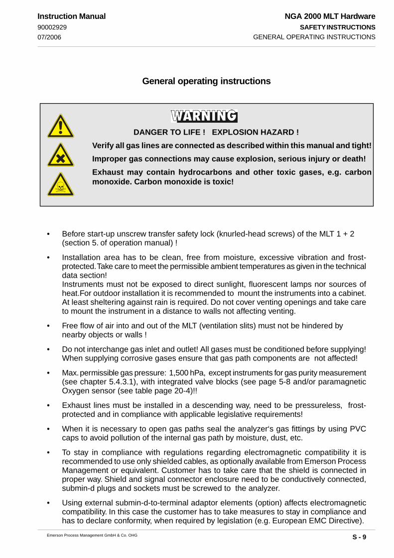
• Before start-up unscrew transfer safety lock (knurled-head screws) of the MLT 1 + 2(section 5. of operation manual) !
• Installation area has to be clean, free from moisture, excessive vibration and frost-protected. Take care to meet the permissible ambient temperatures as given in the technicaldata section!Instruments must not be exposed to direct sunlight, fluorescent lamps nor sources ofheat.For outdoor installation it is recommended to mount the instruments into a cabinet.At least sheltering against rain is required. Do not cover venting openings and take careto mount the instrument in a distance to walls not affecting venting.
• Free flow of air into and out of the MLT (ventilation slits) must not be hindered bynearby objects or walls !
• Do not interchange gas inlet and outlet! All gases must be conditioned before supplying!When supplying corrosive gases ensure that gas path components are not affected!
• Max. permissible gas pressure: 1,500 hPa, except instruments for gas purity measurement(see chapter 5.4.3.1), with integrated valve blocks (see page 5-8 and/or paramagneticOxygen sensor (see table page 20-4)!!
• Exhaust lines must be installed in a descending way, need to be pressureless, frost-protected and in compliance with applicable legislative requirements!
• When it is necessary to open gas paths seal the analyzer‘s gas fittings by using PVCcaps to avoid pollution of the internal gas path by moisture, dust, etc.
• To stay in compliance with regulations regarding electromagnetic compatibility it isrecommended to use only shielded cables, as optionally available from Emerson ProcessManagement or equivalent. Customer has to take care that the shield is connected inproper way. Shield and signal connector enclosure need to be conductively connected,submin-d plugs and sockets must be screwed to the analyzer.
• Using external submin-d-to-terminal adaptor elements (option) affects electromagneticcompatibility. In this case the customer has to take measures to stay in compliance andhas to declare conformity, when required by legislation (e.g. European EMC Directive).
General operating instructions
DANGER TO LIFE ! EXPLOSION HAZARD !Verify all gas lines are connected as described within this manual and tight!Improper gas connections may cause explosion, serious injury or death!Exhaust may contain hydrocarbons and other toxic gases, e.g. carbonmonoxide. Carbon monoxide is toxic!

NGA 2000 MLT HardwareSAFETY INSTRUCTIONS
S - 10 Emerson Process Management GmbH & Co. OHG
Instruction Manual90002929
07/2006ADDITIONAL HINTS FOR UV MEASUREMENT
TOXIC SUBSTANCE !The optional UV lamp contains mercury. Lamp breakage couldresult in mercury exposure ! Mercury is highly toxic !If the lamp is broken, avoid any skin contact to mercury andinhalation of mercury vapors !
UV SOURCE !Ultraviolet light from UV lamp can cause permanent eye damage !Do not look directly at the ultraviolet source !
The optional UV lamp operates with high voltage (Power Supply UVS) !HIGH VOLTAGE !
Additional hints for UV measurement

NGA 2000 MLT HardwareSAFETY INSTRUCTIONS
S - 11Emerson Process Management GmbH & Co. OHG
Instruction Manual90002929
07/2006
Magnetically Operated Front Panel
DANGER TO LIFE !Persons with cardiac pacemakers should absolutely avoid magneticfields !Negative effects on persons beyond those described above caused bymagnetic fields are not known. It is presumed that persons showing allergicreaction on contact with ceramic or metallic material show the samebehavior on contact with magnetic material.
Permanent magnets are surrounded by magnetic fields. These magneticfields can disturb and even destroy sensitive electronic measuring devices,but also mechanical watches, credit cards, etc.Usually a distance of 0.5 m is enough to avoid damages. All sinteredpermanent magnets are hard and brittle. Hitting of sintered permanentmagnets by the magnetic attraction causes splitting into fragments withmany sharp edges. This especially occurs with high energy magnets, andcan also cause skin bruises by high attraction.High energy magnets made of rare-earth materials have to be stored dry,otherwise the surfaces would oxidise. Unprotected operation in a humidenvironment may cause corrosion. Avoid damaging the protective galvaniccoating.A storage in a hydrogen atmosphere destroys these magnets.A demagnetisation is caused when permanent magnet materials have beenexposed in a radioactive radiation for a long time.For air transportation of magnetic material the IATA instructions have to beobserved:Magnetic fields are not allowed to penetrate the package, if necessary themagnets have to be shorted using a metal plate.
MAGNETICALLY OPERATED FRONT PANEL

NGA 2000 MLT HardwareSAFETY INSTRUCTIONS
S - 12 Emerson Process Management GmbH & Co. OHG
Instruction Manual90002929
07/2006
Electrostatic Discharge
The electronic parts of the analyzer can be irreparably damaged if exposedto electrostatic discharge (ESD).The instrument is ESD protected when the covers have been secured andsafety precautions observed. When the housing is open, the internalcomponents are not ESD protected anymore.
Although the electronic parts are reasonable safe to handle, you should be aware of thefollowing considerations:
Best ESD example is when you walked across a carpet and then touched an electrical groundedmetal doorknob. The tiny spark which has jumped is the result of electrostatic discharge(ESD).
You prevent ESD by doing the following:
Remove the charge from your body before opening the housing and maintain during workwith opened housing, that no electrostatic charge can be built up.
Ideally you are opening the housing and working at an ESD - protecting workstation.Here you can wear a wrist trap.
However, if you do not have such a workstation, be sure to do the following procedure exactly:
Discharge the electric charge from your body. Do this by touching a device that is groundedelectrically (any device that has a three - prong plug is grounded electrically when it is pluggedinto a power receptacle).This should be done several times during the operation with opened housing (especially afterleaving the service site because the movement on a low conducting floors or in the air mightcause additional ESDs).
ELECTROSTATIC DISCHARGE

P - 1
NGA 2000 MLT HardwarePREFACE
Emerson Process Management GmbH & Co. OHG
Instruction Manual90002929
12/2006
Preface
a) Analyzer versions - Standard General Purpose Applications
The MLT series of NGA 2000 analyzers offers multi-component, multi-method analysis. Different
measurement methods can be combined in one analyzer.
MLT 1, MLT 2 and MLT 4 (MLT 5) are designed to measure up to 5 gas components while MLT 1
ULCO, MLT 3 and CAT 200 allow up to 4 gas components (including photometer and non-
photometer channels).
For MLT (MLT 1, 2 & CAT 200) with Foundation Fieldbus (FF) a special FF instruction manual
is provided.
NGA 2000 MLT 1 ULCO gas analyzer is specially designed to measure ultra low carbon monoxide.
The analyzer is equipped with a 2nd optical bench including a multi detector assembly (MDA block)
for cross interference compensation in automotive and flue gas applications. Water vapor and
carbon dioxide measurement is used for internal cross interference compensation thus providing
an ultra low CO and CO2 channel as standard. This solution is designed for automotive (Internal
Combustion Engine Emissions, ICEE) and Continuous Emissions Monitoring Systems (CEMS).
An additional COhigh channel is available as option on automotive applications.
For gas purity measurement new quality standards require ultra low CO measurement but not such
high dynamic ranging and cross compensation. Therefore the 2nd bench (MDA) is not used, but
another channel, e.g. ultra low carbon dioxide (ULCO2) can be implemented in MLT 1.
All MLT 2 components are incorporated into a wall-mountable housing with ingress protection code
IP 65 (designed to meet NEMA 4/4X) according to EN 60529. This housing is equipped with
an impact tested front panel according to EN 50014 operated by a magnetically operated touch
panel. The MLT 2 can be purged to remove corrosive or toxic gases with synthetic air or
instrumental air (dry, free of oil, hydrocarbons and corrosive components; 20 to 35 °C purge gas
temperature). If sample gas contains flammable gas components above the lower explosion
limit, the required explosion protection measures (purge/pressurization system) must be
approved by an authorized person (ATEX/CSA-C/US purge system) .
MLT 2 is available with a dual compartment enclosure, too, whereat electronics and photometer/
sensors are installed in two separate housings.
Special high temperature variations of MLT 2 or 3 for physics temperatures up to 120 °C are
optionally available (standard thermostat control: 55 °C; 65 °C as option).
Special versions of MLT 3 are available with suppressed ranges for gas purity measurements
and a corresponding additional manual too (special sample handlingrequirements).

P - 2
NGA 2000 MLT HardwarePREFACE
Emerson Process Management GmbH & Co. OHG
Instruction Manual90002929
12/2006
b) Analyzer versions - Installation in Hazardous Areas
Note!
This manual does not deal with special conditions for analyzers in hazardous areas, related to
installation, operation, maintenance etc. For such applications refer to the separate instruc-tion manuals, delivered together with the analyzers.For installation in hazardous areas the
MLT 2 can be equipped with the appropriate pressurization system acc. to the actual required
explosion protection measures.
Solutions acc. to CENELEC (according to former European EN 50016) use combinations of MLT
2 and an appropriate pressurization system being individually certified (see separate manual
about pressurization system and individual certification report - §10 Elex).
In this case a magnetically operated touch panel or an intrinsically safe front panel (combined with
approved PCB EXI 01for Zone 1, option for Zone 2) is implemented and MLT 2 is combined with
a simplified pressurization for European Ex Zone 2 or with an approved pressurization system for
European Ex Zone 1 (see separate instruction manual).
Additionally the MLT 2 may be equipped with intrinsically safe I/O's (see separate instruction
manual )
MLT 2-NF is a special analyzer version of MLT 2 with Z Purge system for North American Class
1 Zone 2 measurements of non-flammable gases in hazardous areas (CSA-C/US type approved
for Zone 2, see separate instruction manual).
EEx p solutions acc. to ATEX (European Directive for Equipment to be used in Explosive
Atmospheres; mandatory since July 1, 2003) use type approved combinations of MLT 2 and
appropriate pressurization systems (see separate ATEX instruction manual about pressurization
system and certification). The separate ATEX manual covers all EExp Ex Zone 1 solutions as well
as solutions for Ex Zone 2 measuring non-flammable gases. Solutions for measuring
flammable gases in Ex Zone 1 or 2 are described in a separate instruction manual.
For installation acc. to ATEX in Ex Zone 1 and 2 the MLT 2 is always equipped with a
magnetically operated touch panel (see separate manual too). Additionally the MLT 2 may be
equipped with intrinsically safe I/O's (see separate instruction manual).
The CAT 200 analyzer or analyzer module is designed to be installed in hazardous areas, too,
It is consisting of a 1/2-19" MLT 1 analyzer (analyzer module) installed into a flameproof Ex d
enclosure with Ex em junction box. This model is CSA-C/US and ATEX approved for
installation in North-American and European hazardous areas (Ex zone 1).
P - 3
NGA 2000 MLT HardwarePREFACE
Emerson Process Management GmbH & Co. OHG
Instruction Manual90002929
12/2006
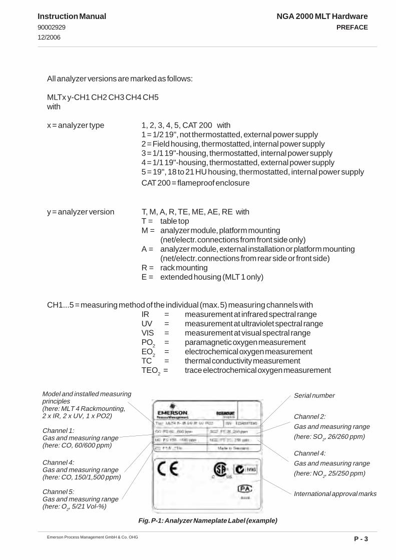
All analyzer versions are marked as follows:
MLTx y-CH1 CH2 CH3 CH4 CH5with
x = analyzer type 1, 2, 3, 4, 5, CAT 200 with1 = 1/2 19", not thermostatted, external power supply2 = Field housing, thermostatted, internal power supply3 = 1/1 19"-housing, thermostatted, internal power supply4 = 1/1 19"-housing, thermostatted, external power supply5 = 19", 18 to 21 HU housing, thermostatted, internal power supplyCAT 200 = flameproof enclosure
y = analyzer version T, M, A, R, TE, ME, AE, RE withT = table topM = analyzer module, platform mounting
(net/electr. connections from front side only)A = analyzer module, external installation or platform mounting
(net/electr. connections from rear side or front side)R = rack mountingE = extended housing (MLT 1 only)
CH1...5 = measuring method of the individual (max. 5) measuring channels withIR = measurement at infrared spectral rangeUV = measurement at ultraviolet spectral rangeVIS = measurement at visual spectral rangePO2 = paramagnetic oxygen measurementEO2 = electrochemical oxygen measurementTC = thermal conductivity measurementTEO2 = trace electrochemical oxygen measurement
Fig. P-1: Analyzer Nameplate Label (example)
Model and installed measuringprinciples(here: MLT 4 Rackmounting,2 x IR, 2 x UV, 1 x PO2)
Channel 1:Gas and measuring range(here: CO, 60/600 ppm)
Serial number
International approval marks
Channel 2:
Gas and measuring range
(here: SO2, 26/260 ppm)
Channel 4:
Gas and measuring range
(here: NO2, 25/250 ppm)
Channel 4:Gas and measuring range(here: CO, 150/1,500 ppm)
Channel 5:Gas and measuring range(here: O2, 5/21 Vol-%)

P - 4
NGA 2000 MLT HardwarePREFACE
Emerson Process Management GmbH & Co. OHG
Instruction Manual90002929
12/2006
c) Analyzer System Architecture
The MLT´s flexibility facilitates the most cost-effective system architecture - elegantly accommo-
dating either “stand-alone” or integrated multi-channel analyzer requirements.
The MLT is available both as an “Analyzer Module” or as an “Analyzer”.
The “Analyzer Module” (AM) is a “blind” analysis unit but retains all the advanced MLT design
features. The AM variant is designed for integration as part of a Multiple NGA 2000 analysis system
or special customer developed networks. The MLT AM novel “blind” packaging and network
functionality allows the user to easily exploit the MLT analyser´s advanced expansion capability.
The MLT Analyzers can be designed as single stand-alone analyzers - complete with control
module functionality and front panel display/operator interface - or as an central interface for
multiple Analyzer Modules with a network board.
In MLT analyzer systems this feature eliminates duplication of the display/operator interface. In
addition to the obvious operational benefits, MLT Analyzers offer significant cost and system
packaging advantages not possible with conventional analyser configurations.
This flexible network communication architecture is shown in Fig. P-4.
ROSEMOUNT NGA 2000NGA 2000
ROSEMOUNT NGA 2000NGA 2000
ROSEMOUNT NGA 2000NGA 2000
ROSEMOUNT NGA 2000NGA 2000
ROSEMOUNT NGA 2000NGA 2000
ROSEMOUNT NGA 2000NGA 2000
ROSEMOUNT NGA 2000NGA 2000
Platform with MLT AMor
19" MLT Analyzer
CLD
FID
PMD
½ 19" MLTAnalyzer
CLD
FID PS
CLD PS
PS
CLD FID
MLT MLT
NG
A N
etw
ork
NG
A N
etw
ork
NGA Network
NGA Network
NG
A N
etw
ork
½ 19" MLTAnalyzer
Platform with MLT AMor
19" MLT Analyzer
NGA Network
Fig. P-2: From separate analyzers to analyzer system

P - 5
NGA 2000 MLT HardwarePREFACE
Emerson Process Management GmbH & Co. OHG
Instruction Manual90002929
12/2006
The modular erection with a bi-direction network makes possible
Single devices (stand-alone analyzers)
- analyzer modules in a platform (separate manual) including optional
inputs and outputs (e.g. SIO/DIO).
- MLT analyzer including optional inputs and outputs (e.g. SIO/DIO).
The interconnection on simple way of analyzer modules including optional local inputs and
outputs (e.g. SIO/DIO) to analyzer systems
- with platform (separate instruction) including system inputs and outputs (SIO/DIO)
- with MLT analyzer including system inputs and outputs (SIO/DIO)
- with customer own control units
For combination possibilities of NGA 2000 MLT I/O´s look at table P-1, please.
Fig. P-3: Example of NGA-cabling
Analyzer Module
Analyzer Module
Power supplyNetwork Cable
24VDC Cable
24VDC Cable
AC DC
Platform
Analyzer Module
Network Cable
AC
DC
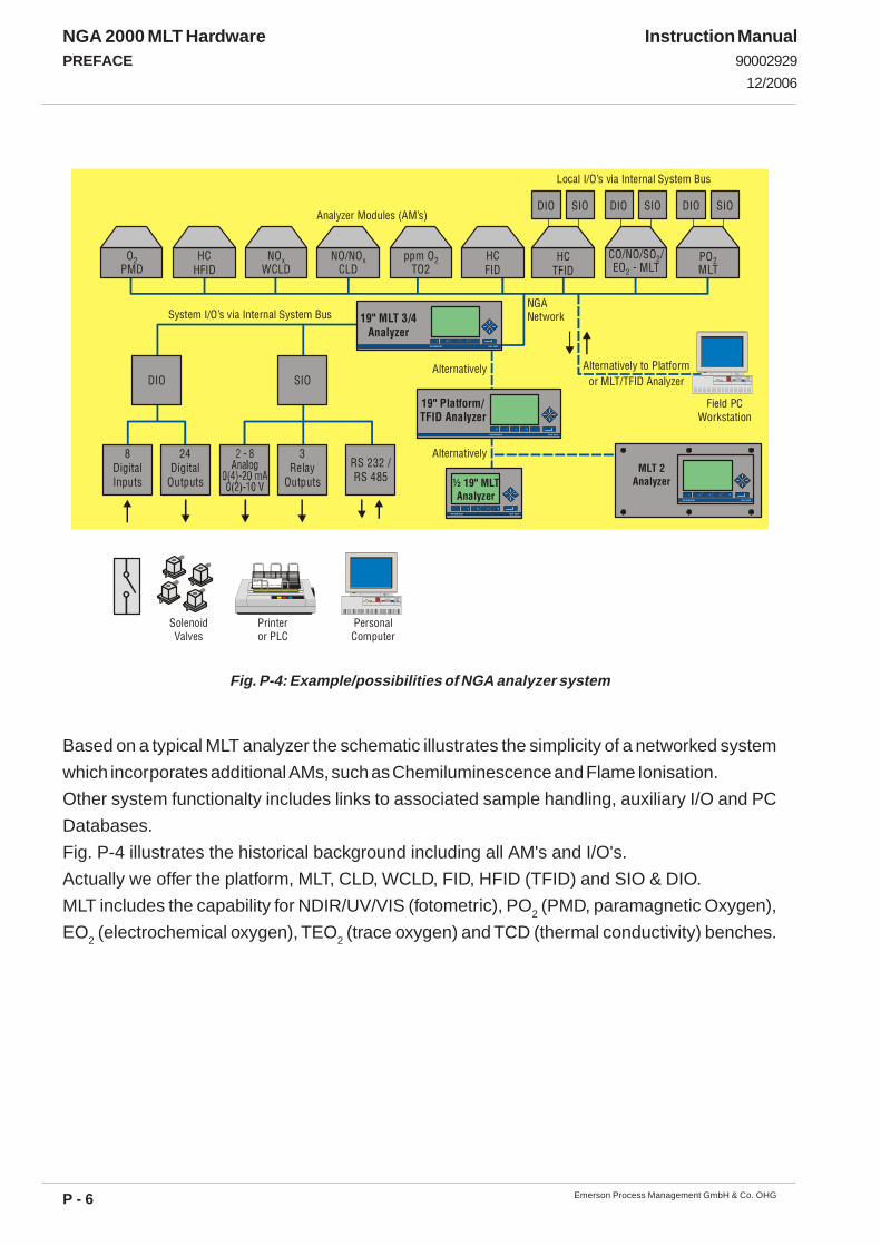
P - 6
NGA 2000 MLT HardwarePREFACE
Emerson Process Management GmbH & Co. OHG
Instruction Manual90002929
12/2006
Fig. P-4: Example/possibilities of NGA analyzer system
Based on a typical MLT analyzer the schematic illustrates the simplicity of a networked system
which incorporates additional AMs, such as Chemiluminescence and Flame Ionisation.
Other system functionalty includes links to associated sample handling, auxiliary I/O and PC
Databases.
Fig. P-4 illustrates the historical background including all AM's and I/O's.
Actually we offer the platform, MLT, CLD, WCLD, FID, HFID (TFID) and SIO & DIO.
MLT includes the capability for NDIR/UV/VIS (fotometric), PO2 (PMD, paramagnetic Oxygen),
EO2 (electrochemical oxygen), TEO2 (trace oxygen) and TCD (thermal conductivity) benches.
Local I/O’s via Internal System Bus
System I/O’s via Internal System BusNGANetwork
Alternatively to Platformor MLT/TFID Analyzer
Printer or PLC
PersonalComputer
SolenoidValves
Field PCWorkstation
8DigitalInputs
24Digital
Outputs
3Relay
Outputs
RS 232 /RS 485
DIO SIO
19" MLT 3/4Analyzer
NGA 200 0ROSEM OUN T
19" Platform/TFID Analyzer
NGA 200 0ROSEM OUN T
Alternatively
Analyzer Modules (AM’s)
OPMD
2 POMLT
2
DIO SIO
HCHFID
NOWCLD
x NO/NOCLD
x
DIO SIO
HCTFID
ppm OTO2
2 HCFID
DIO SIO
CO/NO/SO /EO - MLT
2
2
Alternatively
NG A 2000RO SEMOUN T
NG A 2000RO SEMOUN T
½ 19" MLTAnalyzer
MLT 2Analyzer

P - 7
NGA 2000 MLT HardwarePREFACE
Emerson Process Management GmbH & Co. OHG
Instruction Manual90002929
12/2006
Table P-1: Possibilities of NGA 2000 MLT I/O combinations
System Unit SIO/DIO Configuration MLT analyzer module (AM): • without front panel,
i.e. "blind" without control unit
• can be combined with a platform, a MLT analyzer, a TFID analyzer or a customer developed control unit
⇒ 1 local SIO and 1 local DIO (or 2 local DIO’s) can be installed in the MLT analyzer module
⇒ SIO and DIO can be configured for the MLT AM channels module only
Platform (Control Module Software): • Control unit with front panel • Without measurement channels
⇒ 1 SIO and up to 4 DIO's (or 5 DIO's) can be installed in the platform (CM I/O’s)
⇒ SIO and DIO can be configured
for all MLT channels & AM’s combined with the platform
MLT analyzer (CM plus MLT AM software = MCA software): • Analyzer with front panel • CM and AM software in the same analyzer,
i.e. all functions of the control unit and of the AM are combined in one controller board
⇒ 1 SIO and 1 DIO (or 2 DIO’s) can be installed in the MLT analyzer (CM I/O)
⇒ SIO and DIO can be configured
for all MLT channels & AM’s combined with the MLT analyzer

P - 8
NGA 2000 MLT HardwarePREFACE
Emerson Process Management GmbH & Co. OHG
Instruction Manual90002929
12/2006

NGA 2000 MLT HardwareTECHNICAL DESCRIPTION
1 - 1Emerson Process Management GmbH & Co. OHG
Instruction Manual9000292901/2007
1. Technical Description
1.1 Standard General Purpose Applications
The different analyzers and analyzer modules are assembled in principle identically.All components of analyzers or analyzer modules are incorporated into a housing for platformmounting (MLT 1), a 1/2 19" housing (MLT 1) or a 1/1 19" housing (MLT 3/4).MLT 1 analyzer module housings for platform mounting are available to built-in into a NGA platformonly (M) or for external installation and platform mounting (A) connected via NGA network.The 1/2 19" and 1/1 19" housings are available as rack mounting (R) or as table-top (T) versions.For analyzer modules there is mounted a blind plate instead of an operation front panel.
An IP 65 protected field housing (MLT 2) for outdoor installation is available, too.This enclosure isintended to be wall mounted.
1.2 Installation in Hazardous Areas
Note!This manual does not deal with special conditions for analyzers in hazardous areas, related toinstallation, operation, maintenance etc. For such applications refer to the separate instruc-tion manuals, delivered together with the analyzers.
For installation in hazardous areas the MLT 2 analyzer or analyzer module is provided with anadapted pressurization system (ATEX type approved for Zone 1 resp. Zone 2 in Europe) and animpact tested magnetically operated front panel. Optionally intrinsically safe signal couplers areavailable, too.A simplified Z Purge system permits installation in North America Zone 2 environments. TheMLT 2-NF is type approved for non-flammable sample gas acc. to CSA-C/US for both Canadaand US.
The CAT 200 analyzer or analyzer module, designed to be installed in hazardous areas, too,comprised of a 1/2-19" analyzer analyzer installed into a flameproof enclosure. This model is CSA-C/US and ATEX approved for installation in North-American and European hazardous areas.
STANDARD GENERAL PURPOSE APPLICATIONS/INSTALLATION IN HAZARDOUS AREAS
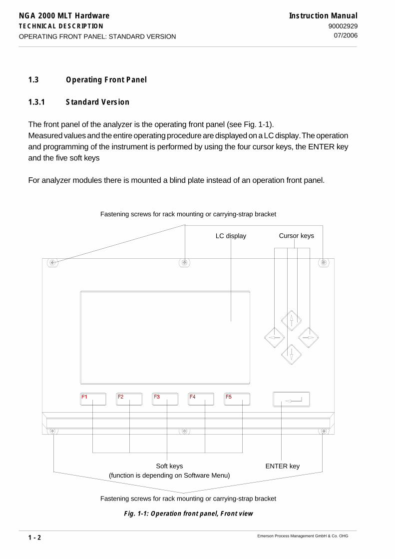
NGA 2000 MLT HardwareTECHNICAL DESCRIPTION
1 - 2 Emerson Process Management GmbH & Co. OHG
Instruction Manual90002929
07/2006
Fig. 1-1: Operation front panel, Front view
OPERATING FRONT PANEL: STANDARD VERSION
1.3 Operating Front Panel
1.3.1 Standard Version
The front panel of the analyzer is the operating front panel (see Fig. 1-1).Measured values and the entire operating procedure are displayed on a LC display. The operationand programming of the instrument is performed by using the four cursor keys, the ENTER keyand the five soft keys
For analyzer modules there is mounted a blind plate instead of an operation front panel.
Fastening screws for rack mounting or carrying-strap bracket
ENTER key
LC display Cursor keys
Soft keys(function is depending on Software Menu)
Fastening screws for rack mounting or carrying-strap bracket

NGA 2000 MLT HardwareTECHNICAL DESCRIPTION
1 - 3Emerson Process Management GmbH & Co. OHG
Instruction Manual9000292907/2006
1.3.2 Magnetically Operated Touch Panel
Analyzers intended either to be used in hazardous area or for outdoor usage (e.g. MLT 2 or CAT 200)are provided with a magnetically operated touch panel. This special version ensures ingressprotection (IP) and resistance against mechanical shocks. On account of its design it requires somespecial measures to operate the corresponding analyzer in a safe manner, so read the followinginstructions carefully!
1.3.2.1 Magnetic Touch Panel Elements
Whereas standard front panels are using keys for operating the analyzer the magnetically operatedtouch panel uses contactless technology instead. This results in a slightly different design:Each standard panel key is replaced by a reed relay located behind the front panel design foil. (CAT200, MLT 2 only: The sequence of the 4 keys at the right side has changed due to ergonomic reasons.)
Fig. 1-2: Magnetically Operated Touch Panel, Front view
OPERATING FRONT PANEL: MAGNETICALLY OPERATED TOUCH PANEL

NGA 2000 MLT HardwareTECHNICAL DESCRIPTION
1 - 4 Emerson Process Management GmbH & Co. OHG
Instruction Manual90002929
07/2006
1.3.2.2 Accessories
To operate the magnetically operated touch panel a special tool (actuator) is required. The followingpicture shows this tool as it should be provided together with your analyzer. If it is missing pleasecontact your local sales office.
1.3.2.3 Operating the Touch Panel
The touch panel is operated by activating the reed relays using the actuator.This is done by holding that actuator’s end in front of the key that is equipped with 2 small magnets.As the reed relays are installed alternating vertical and horizontal to prevent accidentally activationof an adjacent key, the actuator has to be aligned the same way.The design foil shows for each key how the actuator has to be aligned using the symbols
„ “ and „ “ :
OPERATING FRONT PANEL: MAGNETICALLY OPERATED TOUCH PANEL
Fig. 1-4c: Vertically aligned, activating F5Fig. 1-4b: Horizontally aligned, activating F4
Fig. 1-4a: Symbols showing actuator alignment
Fig. 1-3b: Magneticactuator,
view at magnets
Fig. 1-3a: Magnetic actuator
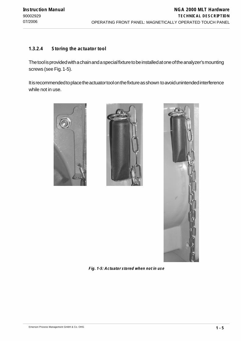
NGA 2000 MLT HardwareTECHNICAL DESCRIPTION
1 - 5Emerson Process Management GmbH & Co. OHG
Instruction Manual9000292907/2006
1.3.2.4 Storing the actuator tool
The tool is provided with a chain and a special fixture to be installed at one of the analyzer’s mountingscrews (see Fig. 1-5).
It is recommended to place the actuator tool on the fixture as shown to avoid unintended interferencewhile not in use.
OPERATING FRONT PANEL: MAGNETICALLY OPERATED TOUCH PANEL
Fig. 1-5: Actuator stored when not in use

NGA 2000 MLT HardwareTECHNICAL DESCRIPTION
1 - 6 Emerson Process Management GmbH & Co. OHG
Instruction Manual90002929
07/2006
1.4 MLT 1
The different analyzers and analyzer modules are assembled in principle identically.All components of analyzers or analyzer modules are incorporated into a housing for platformmounting (MLT 1) or a 1/2 19" housing (MLT 1).The equipment is specified for an operating voltage of 24 V DC (± 5 %).There are mounted optional different components at the rear side of the front panel (Fig. 1-7).
1.4.1 MLT 1 1/2 19" housing
The 1/2 19" and 1/1 19" housings are available as rack mounting (R) or as table-top (T) versions.For analyzer modules there is mounted a blind plate instead of an operation front panel.On the rear panel the connector for 24 V dc supply (MLT 1 [not MLT (M)]), the gas connections,the network connections and the connectors of optional PCBs (see optional, separate OperationManuals) are accommodated.
MLT 1 (1/2 19" HOUSING)
Fig. 1-6: MLT analyzer, Front view
Fastening screws for rack mounting or carrying-strap bracket
Fastening screws for rack mounting or carrying-strap bracket
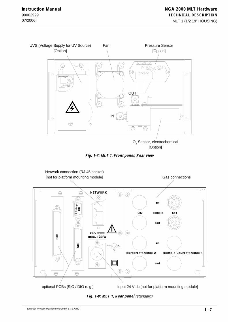
NGA 2000 MLT HardwareTECHNICAL DESCRIPTION
1 - 7Emerson Process Management GmbH & Co. OHG
Instruction Manual9000292907/2006
Fig. 1-7: MLT 1, Front panel, Rear view
Fig. 1-8: MLT 1, Rear panel (standard)
MLT 1 (1/2 19" HOUSING)
IN
OUT
FanUVS (Voltage Supply for UV Source)[Option]
Pressure Sensor[Option]
O2 Sensor, electrochemical
[Option]
Network connection (RJ 45 socket)[not for platform mounting module] Gas connections
Input 24 V dc [not for platform mounting module]optional PCBs [SIO / DIO e. g.]
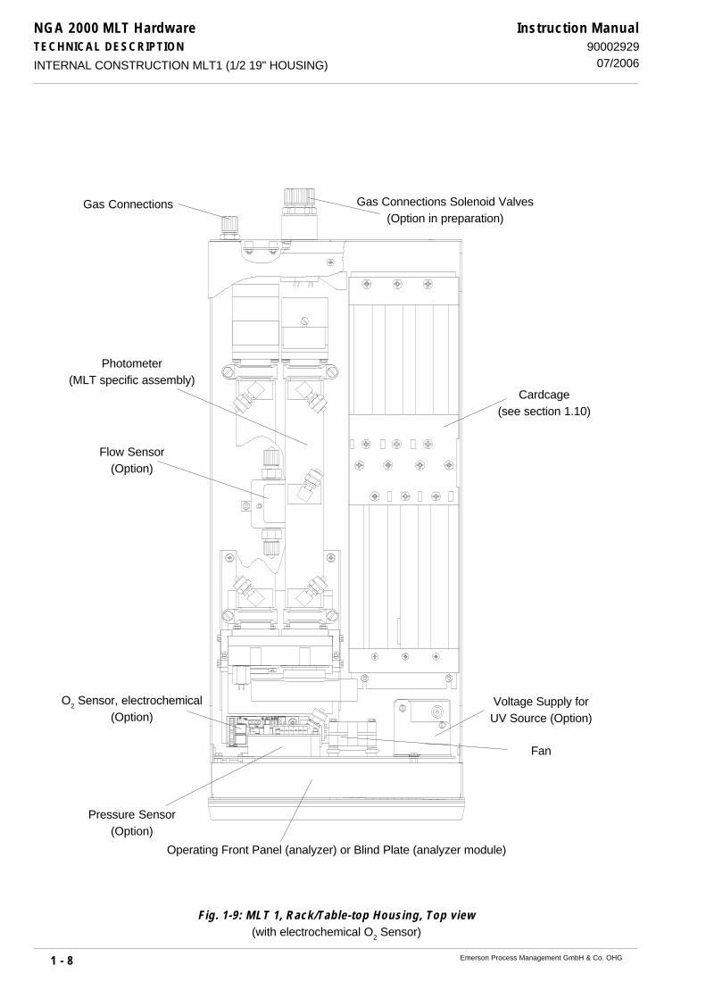
NGA 2000 MLT HardwareTECHNICAL DESCRIPTION
1 - 8 Emerson Process Management GmbH & Co. OHG
Instruction Manual90002929
07/2006
Fig. 1-9: MLT 1, Rack/Table-top Housing, Top view(with electrochemical O2 Sensor)
INTERNAL CONSTRUCTION MLT1 (1/2 19" HOUSING)
Voltage Supply forUV Source (Option)
Pressure Sensor(Option)
Fan
O2 Sensor, electrochemical
(Option)
Photometer(MLT specific assembly)
Flow Sensor(Option)
Gas Connections Gas Connections Solenoid Valves(Option in preparation)
Operating Front Panel (analyzer) or Blind Plate (analyzer module)
Cardcage(see section 1.10)
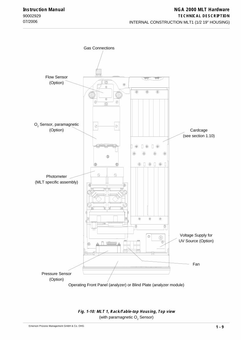
NGA 2000 MLT HardwareTECHNICAL DESCRIPTION
1 - 9Emerson Process Management GmbH & Co. OHG
Instruction Manual9000292907/2006
Fig. 1-10: MLT 1, Rack/Table-top Housing, Top view(with paramagnetic O2 Sensor)
INTERNAL CONSTRUCTION MLT1 (1/2 19" HOUSING)
Operating Front Panel (analyzer) or Blind Plate (analyzer module)
Photometer(MLT specific assembly)
Flow Sensor(Option)
Gas Connections
Voltage Supply forUV Source (Option)
Pressure Sensor(Option)
Fan
Cardcage(see section 1.10)
O2 Sensor, paramagnetic
(Option)

NGA 2000 MLT HardwareTECHNICAL DESCRIPTION
1 - 10 Emerson Process Management GmbH & Co. OHG
Instruction Manual90002929
07/2006
Fig. 1-11: MLT 1, Rack/Table-top Housing extended, Top view(with paramagnetic O2 Sensor)
INTERNAL CONSTRUCTION MLT1 (1/2 19" HOUSING)
Voltage Supply forUV Source (Option)
Fan
Cartridge(see Item 1.10)
Flow Sensor(Option)
Pressure Sensor(Option)
Operating Front Panel(analyzer) or
Blind Plate (analyzer mod-ule)
Photometer(MLT specific assembly)
Gas ConnectionsGas Connections Solenoid Valves
(Option in preparation)
O2 Sensor, paramagnetic
(Option)

NGA 2000 MLT HardwareTECHNICAL DESCRIPTION
1 - 11Emerson Process Management GmbH & Co. OHG
Instruction Manual9000292901/2007 MLT1 ULCO
1.4.2 MLT 1 ULCO
NGA 2000 MLT 1 ULCO gas analyzer is specially designed to measure ultra low carbonmonoxide in a matrix with high water vapor and/or carbon dioxide contents. The analyzer isequipped with a 2nd optical bench including a multi detector assembly (MDA block) for crossinterference compensation, especially being designed for automotive and flue gasapplications. Water vapor and carbon dioxide measurement is used for internal crossinterference compensation thus providing an ultra low CO and percentage CO
2 channel as
standard. This solution is designed for automotive (Internal Combustion Engine Emissions,ICEE) and Continuous Emissions Monitoring Systems (CEMS). An additional CO
high channel
is available as option on automotive applications. The water vapor channel is designed formeasuring crossinterferences only but coudl be used as a measuring channel too but withoutoffering the same accuracy as a "normal" measuring channel. This means that teh standardspecifications are not applicable for this special water vapor channel.
For gas purity measurement new quality standards require ultra low CO measurement but notsuch high dynamic ranging and cross compensation.Therefore the 2nd bench (MDA) is not used, but another channel, e.g. ultra low carbon dioxide(ULCO
2) can be implemented in MLT 1.

NGA 2000 MLT HardwareTECHNICAL DESCRIPTION
1 - 12 Emerson Process Management GmbH & Co. OHG
Instruction Manual90002929
07/2006
Fig. 1-12: MLT 1 ULCO, Rack/Table-top Housing, Top view
INTERNAL CONSTRUCTION MLT1-ULCO
Operating Front Panel (analyzer) or Blind Plate (analyzer module)
Multi Detector Assembly MDA(CO
2/H
2O detector for
cross compensationand CO
2 measurement,
ICEE/CEMS only)
Cardcage(see Item 1.10)
Flow Sensor(Option)
Gas Connections
Pressure Sensor(Option)
Fan
Detector COlow
Detector COhigh
(Option, ICEE/CEMS only)

NGA 2000 MLT HardwareTECHNICAL DESCRIPTION
1 - 13Emerson Process Management GmbH & Co. OHG
Instruction Manual9000292907/2006 MLT1 (HOUSING FOR PLATFORM MOUNTING)
1.4.3 MLT 1 Housing for platform mounting
MLT 1 analyzer module housings for platform mounting are available to built-in into a NGA platformonly (M) or for external installation and platform mounting (A) connected via NGA network.Analyzer modules for platform mounting have a blind plate too (Fig. 1-x).Additional the necessary electrical connections for platform mounting (24 V dc and network) arebrought out to this blind plate. For external installation of analyzer module (A) the connections onfrontside are closed with a blind plate to be in agreement with the CE conformity. For platformmounting of the module remove this blind plate.
For analyzer module (A) [external installation or platform mounting] it is notallowed to supply the module from front and rear simultaneously !For external installation connections on frontside absolutely have to closedwith the blind plate delivered from our factory to be in agreement with the CEconformity.!
Fig. 1-13: MLT 1 analyzer module (Platform mounting), Front panel, Front view
Network
24 V dcIN
Retention pins

NGA 2000 MLT HardwareTECHNICAL DESCRIPTION
1 - 14 Emerson Process Management GmbH & Co. OHG
Instruction Manual90002929
07/2006INTERNAL CONSTRUCTION MLT1 (HOUSING FOR PLATFORM MOUNTING)
Fig. 1-14: MLT 1, Platform mounting, Top view(with electrochemical O2 Sensor)
Cardcage(see Item 1.10)
Voltage Supply forUV Source (Option)
Pressure Sensor(Option)
24 V dc Input / Network
Fan
O2 Sensor, electrochemical
(Option)
Photometer(MLT specific assembly)
Flow Sensor(Option)
Gas Connections Gas Connections Solenoid Valves(Option in preparation)

NGA 2000 MLT HardwareTECHNICAL DESCRIPTION
1 - 15Emerson Process Management GmbH & Co. OHG
Instruction Manual9000292907/2006
Fig. 1-15: MLT 1, Platform mounting, Top view(with paramagnetical O2 Sensor)
INTERNAL CONSTRUCTION MLT1 (HOUSING FOR PLATFORM MOUNTING)
Photometer(MLT specific assembly)
Cardcage(see Item 1.10)
O2 Sensor, paramagnetic
(Option)
Flow Sensor(Option)
Gas Connections
Voltage Supply forUV Source (Option)
Pressure Sensor(Option) 24 V dc Input / Network
Fan

NGA 2000 MLT HardwareTECHNICAL DESCRIPTION
1 - 16 Emerson Process Management GmbH & Co. OHG
Instruction Manual90002929
07/2006
Fig. 1-16: MLT 1, Platform mounting extended, Top view(with paramagnetic O2 Sensor)
INTERNAL CONSTRUCTION MLT1 (HOUSING FOR PLATFORM MOUNTING)
Voltage Supply forUV Source (Option)
Cardcage(see Item 1.10)
Flow Sensor(Option)
Pressure Sensor(Option)
Photometer(MLT specific assembly)
Gas ConnectionsGas Connections Solenoid Valves
(Option in preparation)
Fan
24 V dc Input /Network
O2 Sensor, paramagnetic
(Option)

NGA 2000 MLT HardwareTECHNICAL DESCRIPTION
1 - 17Emerson Process Management GmbH & Co. OHG
Instruction Manual9000292907/2006 MLT2 (FIELD HOUSING)
1.5 MLT 2 (Field Housing)
With MLT 2 Emerson Process Management offers a gas analyzer designed for wall mounting andoutdoor installation due to it‘s stainless steel enclosure.All MLT 2 components are incorporated into a wall-mountable housing with ingress protection codeIP 65 (approx. NEMA 4/4X) according to EN 60529.The optional impact protected front panel enables installation at harsh locations (or even inhazardous area when combined with a pressurization system for the enclosure).Such analyzers are contactless operated using a special magnetic tool.All interface signals (partial options) are accessible on internal screw terminal blocks. That appliesto mains power supply, too..The MLT 2 can be purged to remove corrosive or toxic gases with synthetic air or instrumental air(dry, free of oil, hydrocarbons and corrosive components; 20 to 35 °C purge gas temperature). Ifsample gas contains flammable gas components above the lower explosion limit, the requiredexplosion protection measures (purge system) must be approved by an authorized person (purgesystem) .MLT 2 is available with a dual compartment enclosure, too, whereat electronics and photometer/sensors are installed in two separate housings.A special high temperature variation of MLT 2 for temperatures up to 120 °C is optionally available(standard: 55 °C; 65 °C as option).
The analyzer is specified for an operating voltage of 230 V AC or 120 V AC resp., 47-63 Hz.Built-in power supply (manual switch between 230/120 VAC) is either power supply of type SL5or of type SL10
For installation in hazardous areas the MLT 2 is provided with an adapted pressurization system(ATEX type approved for Zone 1 resp. Zone 2 in Europe) and an impact tested magneticallyoperated front panel. Optionally intrinsically safe signal couplers are available, too.A simplified z-purge system permits installation in North America Zone 2 environments.
This current instruction manual covers using the MLT 2 analyzer for generalpurpose applications only!
Installation, startup and maintenance for operation in hazardous areas are de-scribed in detail in a separate instruction manual, shipped together with eachsuch analyzer and are not subject of the current instruction manual!

NGA 2000 MLT HardwareTECHNICAL DESCRIPTION
1 - 18 Emerson Process Management GmbH & Co. OHG
Instruction Manual90002929
07/2006
MLT 2 -- HEAVY INSTRUMENTS !The analyzer variation MLT 2 intended to be wall mounted and/or outdoorinstalled weigh up to 35 kg, depending on included options!Use two person and/or suitable tools for transportation and lifting theseinstruments!Take care to use anchors and bolts specified to be used for the weight ofthe units!Take care the wall or stand the unit is intended to be installed at is solidand stable to hold the units!
Connection of mains and interface signals are to be established via internalscrew terminal blocks. This requires working inside an opened analyzer,near by potentially live components!Installation of this analyzer is allowed by qualified personnel only, familiarwith the potential risks of working near live components!The model MLT 2 (field housing) does not provide a mains switch. A mainsswitch or circuit breaker must be provided in the building installation. Thisswitch has to be installed near by the analyzer, must be easily operatoraccessible and has to be designated as disconnector for the analyzer.Cables for external data processing must be double insulated for mainsvoltage. If not available, signal cables inside the analyzer must be installedwith a distance of at least 5 mm to mains cables. Distance has to be ensuredpermanently, e.g. by using cable ties!
Risk of electric shock!MLT 2 analyzers provide earth connection terminals. To minimize risk ofelectric shock the enclosure must be connected to earth! Thereforeconnecting the analyzer is allowed only by using a 3 pole mains cableproviding a separate earthing conductor.Any interruption of the earthing conductor inside or outside the analyzer aswell as loosening the earthing connection may cause serious injury! Intendedinterruption of earthing connections is not permissible!
MLT2 (FIELD HOUSING)

NGA 2000 MLT HardwareTECHNICAL DESCRIPTION
1 - 19Emerson Process Management GmbH & Co. OHG
Instruction Manual9000292907/2006
Fig. 1-17a: Front view MLT 2 (Standard housing/Standard operation front panel)
Fig. 1-17b: Front view MLT 2 (Dual compartment housing/Standard operation front panel)
MLT2 (FIELD HOUSING)
Operation frontpanel
Front panel
Fastenerfront panel
Wall mountingholder
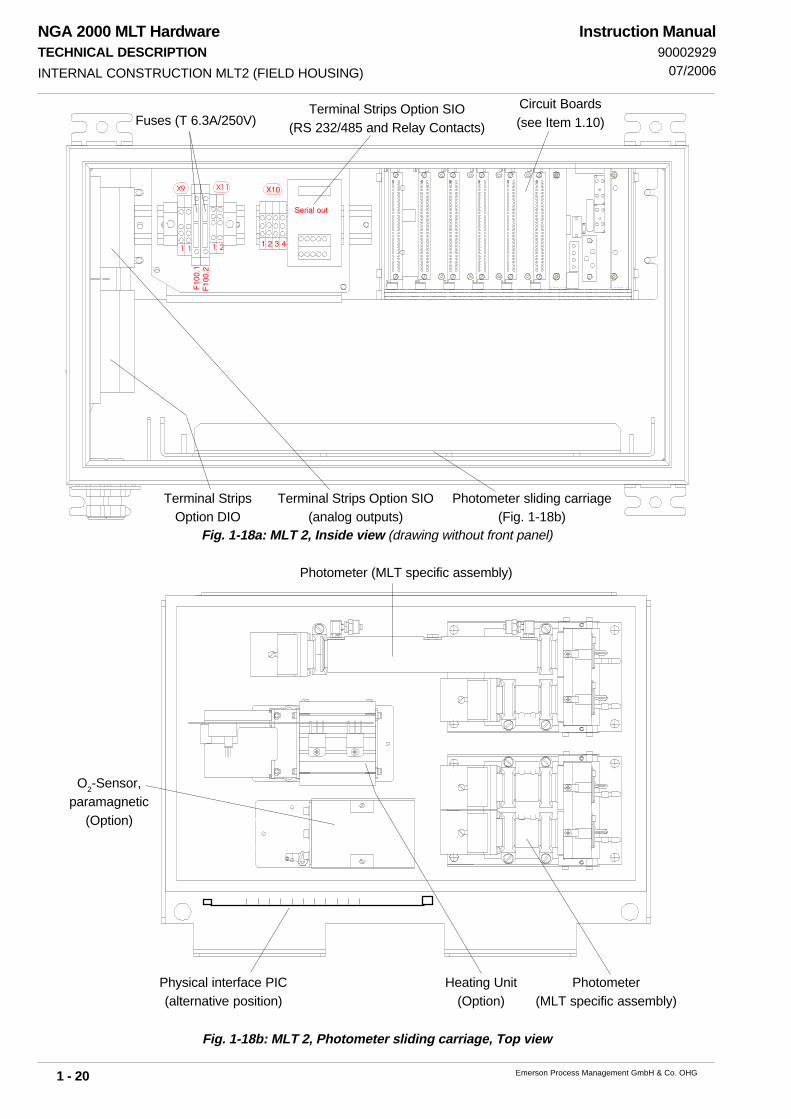
NGA 2000 MLT HardwareTECHNICAL DESCRIPTION
1 - 20 Emerson Process Management GmbH & Co. OHG
Instruction Manual90002929
07/2006
Fig. 1-18b: MLT 2, Photometer sliding carriage, Top view
Fig. 1-18a: MLT 2, Inside view (drawing without front panel)
INTERNAL CONSTRUCTION MLT2 (FIELD HOUSING)
O2-Sensor,
paramagnetic(Option)
Photometer (MLT specific assembly)
Heating Unit(Option)
Photometer(MLT specific assembly)
Photometer sliding carriage(Fig. 1-18b)
Terminal Strips Option SIO(RS 232/485 and Relay Contacts)
Circuit Boards(see Item 1.10)
21
X11X9
1 1
Fuses (T 6.3A/250V)
Terminal StripsOption DIO
Terminal Strips Option SIO(analog outputs)
Physical interface PIC(alternative position)

NGA 2000 MLT HardwareTECHNICAL DESCRIPTION
1 - 21Emerson Process Management GmbH & Co. OHG
Instruction Manual9000292907/2006
1.6 MLT 3
All components of analyzers or analyzer modules are incorporated into a 1/1 19" housing.The housings are available as rack mounting (R) or as table-top (T) versions. For analyzer modulesthere is mounted a blind plate instead of an operation front panel.The equipment has an internal power supply with “autoranging” for operating voltages of 230 VAC or 120 V AC resp., 47-63 Hz.
Fig. 1-19: MLT 3 (standard) (1/1 19" housing), front view
Fig. 1-20: MLT 3 (standard version), Rear view
MLT3
Network connection(RJ 45 socket)
Input 230/120 V ac (UPS 01 T) Gas connectionsoptional PCB [SIO/DIO e.g.]

NGA 2000 MLT HardwareTECHNICAL DESCRIPTION
1 - 22 Emerson Process Management GmbH & Co. OHG
Instruction Manual90002929
07/2006
Fig. 1-21: MLT 3 (standard version), Top view
INTERNAL CONSTRUCTION MLT3
Gas Connections Photometer(MLT specific assembly)
Operating Front Panel (ana-lyzer) or
Blind Plate (analyzer module)
Power Supply(UPS 01 T)
O2 Sensor,
paramagnetic(Option)
Flow Sensor(Option)
Pressure Sensor(Option)
Voltage Supply forUV Source (Option)
O2 Sensor (Option),electrochemical
Fan
Cardcage(see Item 1.10)
Fine Dust Filter(Option)
Gas Sampling Pump(Option)
HeatingUnit

NGA 2000 MLT HardwareTECHNICAL DESCRIPTION
1 - 23Emerson Process Management GmbH & Co. OHG
Instruction Manual9000292901/2007
1.6.1 MLT 3 (Gas purity measurement)
Special versions of MLT 3 are available with suppressed ranges for gas purity measurements andmeasurements requiring physics thermostated up to 120 °C - see separate manual for gaspurity with suppressed ranges.
Example and short description of the main deviations from standard MLT 3:Compared with “standard MLT 3 version” the “MLT 3 for gas purity measurement” can beequipped with a divided front panel.On the right side there is the operation front panel (analyzer) or a blind plate (analyzer module)resp.On the left side there is built-in one flow meter and as option one quick shutoff connector as samplegas inlet.Is the instrument is not equipped with a solenoid valve block, there can be built-in as option amanual 4/2-way-valve to switch to sample gas, zero gas or span gas.For more detailed informations use the special instruction manual for this application.
Fig. 1-22a: MLT 3 (example for gas purity measurement), front view
MLT3 (GAS PURITY MEASUREMENT)
Flow meter Operation front panelQuick shutoff connector(sample ges input, option)
Manual 4/2-way-valve(option)
Rosemount Analytical NGA 2000
F3 F4 F5F2F1
Additional to “standard MLT 3 version” (identical on the left part) the “MLT 3 for gas puritymeasurement” is equipped with a solenoid valve block for the supply of sample gas, zero gasand span gas, controlled by the analyzer. The control will be done with the relay outputs of I/O Board “SIO” via an external connection cable “SIO Solenoid Valve Block” (pinassignments look at Fig. 21-4).
The necessary gas connections are placed here too and are used and marked analyzerspecific (see Fig. 1-23). The outlet of the valve block is connected to the MLT 3 gas inlet.

NGA 2000 MLT HardwareTECHNICAL DESCRIPTION
1 - 24 Emerson Process Management GmbH & Co. OHG
Instruction Manual90002929
01/2007MLT3 (GAS PURITY MEASUREMENT)
Fig. 1-22b: MLT 3 (example for gas purity measurement), Rear view
1.6.2 MLT 3HT (high temperature measurement)
As a special versions MLT 3HT is available for measurements requiring physics thermostatedup to 120 °C. The physical section is parted in a HT part (special heating and isolation) for allcomponents being in contact with sample gas - SS tubing, fine dust/safety filter, needle valve,calibration valve (depending on options). The isolation (filter) cell, chopper & detector areoutside of the heated room together with a temperature controller and ventilator. The heatedline and external pump (with heated head) need isolation at any connection/ fitting:
Heated SectionwithSS tubing,safety filter,
sample gas cell
Isolation cell,
chopper &
detector
Fig. 1-23: MLT 3HT (example for high temperature measurement), Top/ front view
Temperature Controller/ Ventilator (outlet filter)
Gas inlet/ outlet fittings
NET
WO
RK
DIG
ITAL
I/O
AN
ALO
G I/
O
SER
IAL
I/O
! 2
30/1
20 V
50/
60 H
zm
ax.
240
VA
PCB “SIO” Gas connections(analyzer specific)
Input 230/120 V ac(PS UPS 01 T)
Solenoid Valve Block (Option)
Sub.-min. D, 9 pole(connection to PCB “SIO”)
Sub.-min. D, 9 pole(to Solenoid Valve Block Option)
Span gas
Exhaust
Zero gas
Sample gas

NGA 2000 MLT HardwareTECHNICAL DESCRIPTION
1 - 25Emerson Process Management GmbH & Co. OHG
Instruction Manual9000292907/2006
Fig. 1-24: MLT 3 (gas purity measurement), Top view
INTERNAL CONSTRUCTION MLT3 (GAS PURITY MEASUREMENT)
Gas connections Photometer(MLT specific assembly)
Operating Front Panel(analyzer) or
Blind Plate (analyzer module)
Power Supply(UPS 01 T)
Pressureregulator
Flow meter Pressure sensor
Fan
Cardcage(see Item 1.10)
Manual 4/2-way-valve(Option)
HeatingUnit
O2 Sensor,
paramagnetic (Option)
Solenoid valve block(Option)

NGA 2000 MLT HardwareTECHNICAL DESCRIPTION
1 - 26 Emerson Process Management GmbH & Co. OHG
Instruction Manual90002929
07/2006
Fig. 1-25: MLT 4 (1/1 19" housing), front view
Fig. 1-26: MLT 4, Rear view
MLT4
1.7 MLT 4
All components of analyzers or analyzer modules are incorporated into a 1/1 19" housing.The housings are available as rack mounting (R) or as table-top (T) versions. For analyzer modulesthere is mounted a blind plate instead of an operation front panel.The equipment is specified for an operating voltage of 24 V DC (± 5 %).
Network connection (RJ 45 socket)
optional PCB [SIO/DIO e.g.] Input 24 V dc Gas connections

NGA 2000 MLT HardwareTECHNICAL DESCRIPTION
1 - 27Emerson Process Management GmbH & Co. OHG
Instruction Manual9000292907/2006
Fig. 1-27: MLT 4, Rack/Table-top Housing, Top view
INTERNAL CONSTRUCTION MLT4
Gas Connections O2 Sensor, paramagnetic
(Option)
Operating Front Panel (ana-lyzer) or
Blind Plate (analyzer module)
Photometer(MLT specific assembly)
Photometer(MLT specific
assembly)
Voltage Supply forUV Source (Option)
Voltage Supply forUV Source (Option)
Fan
Cardcage(see Item 1.10)
HeatingUnit
O2 Sensor (Option),electrochemical
Gas Connections
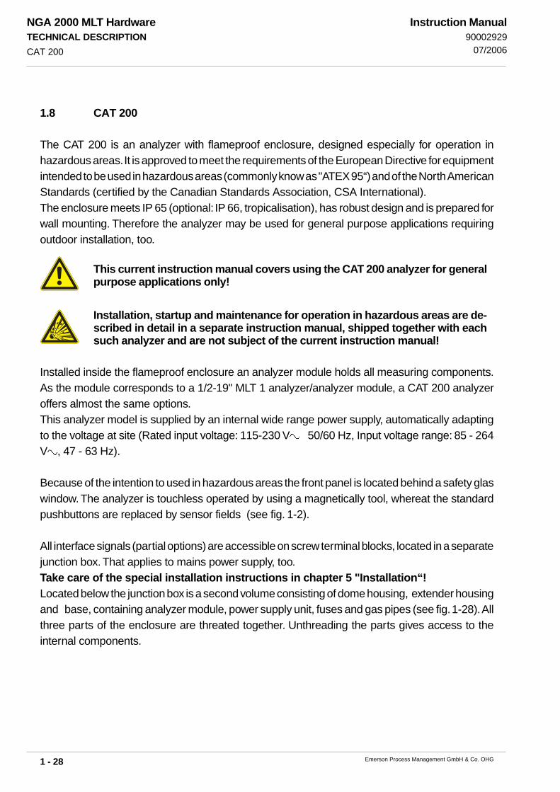
NGA 2000 MLT HardwareTECHNICAL DESCRIPTION
1 - 28 Emerson Process Management GmbH & Co. OHG
Instruction Manual90002929
07/2006CAT 200
1.8 CAT 200
The CAT 200 is an analyzer with flameproof enclosure, designed especially for operation inhazardous areas. It is approved to meet the requirements of the European Directive for equipmentintended to be used in hazardous areas (commonly know as "ATEX 95“) and of the North AmericanStandards (certified by the Canadian Standards Association, CSA International).The enclosure meets IP 65 (optional: IP 66, tropicalisation), has robust design and is prepared forwall mounting. Therefore the analyzer may be used for general purpose applications requiringoutdoor installation, too.
This current instruction manual covers using the CAT 200 analyzer for generalpurpose applications only!
Installation, startup and maintenance for operation in hazardous areas are de-scribed in detail in a separate instruction manual, shipped together with eachsuch analyzer and are not subject of the current instruction manual!
Installed inside the flameproof enclosure an analyzer module holds all measuring components.As the module corresponds to a 1/2-19" MLT 1 analyzer/analyzer module, a CAT 200 analyzeroffers almost the same options.This analyzer model is supplied by an internal wide range power supply, automatically adaptingto the voltage at site (Rated input voltage: 115-230 V 50/60 Hz, Input voltage range: 85 - 264V , 47 - 63 Hz).
Because of the intention to used in hazardous areas the front panel is located behind a safety glaswindow. The analyzer is touchless operated by using a magnetically tool, whereat the standardpushbuttons are replaced by sensor fields (see fig. 1-2).
All interface signals (partial options) are accessible on screw terminal blocks, located in a separatejunction box. That applies to mains power supply, too.Take care of the special installation instructions in chapter 5 "Installation“!Located below the junction box is a second volume consisting of dome housing, extender housingand base, containing analyzer module, power supply unit, fuses and gas pipes (see fig. 1-28). Allthree parts of the enclosure are threated together. Unthreading the parts gives access to theinternal components.

NGA 2000 MLT HardwareTECHNICAL DESCRIPTION
1 - 29Emerson Process Management GmbH & Co. OHG
Instruction Manual9000292907/2006
CAT 200 -- HEAVY INSTRUMENTS !The analyzer variation CAT 200 intended to be wall mounted and/or outdoorinstalled weigh up to 70 kg, depending on included options!Use two person and/or suitable tools for transportation and lifting theseinstruments!Take care to use anchors and bolts specified to be used for the weight ofthe units!Take care the wall or stand the unit is intended to be installed at is solidand stable to hold the units!
Connection of mains and interface signals are to be established via internalscrew terminal blocks. This requires working inside an opened analyzer,near by potentially live components!Installation of this analyzer is allowed by qualified personnel only, familiarwith the potential risks of working near live components!The model CAT 200 does not provide a mains switch. A mains switch orcircuit breaker must be provided in the building installation. This switchhas to be installed near by the analyzer, must be easily operator accessibleand has to be designated as disconnector for the analyzer.The Junction Box must be protected by fuse supply which has a breakingcapacity adjusted to the short circuit of the equipment. The 10 A fuse has tobe installed in the building installation!
Risk of electric shock!CAT 200 analyzers provide earth connection terminals. To minimize risk ofelectric shock the enclosure must be connected to earth! Thereforeconnecting the analyzer is allowed only by using a 3 pole mains cableproviding a separate earthing conductor.Any interruption of the earthing conductor inside or outside the analyzer aswell as loosening the earthing connection may cause serious injury! Intendedinterruption of earthing connections is not permissible!
CAT 200

NGA 2000 MLT HardwareTECHNICAL DESCRIPTION
1 - 30 Emerson Process Management GmbH & Co. OHG
Instruction Manual90002929
07/2006
1 Eye bolts (2 pcs)2 Cable glands for signal cables (3 pcs max)3 Eye bolts (2 pcs)4 Mounting holes (4 pcs.)5 Base6 Extender housing
7 Dome housing8 Front panel behind safety glass9 Interlock screw10 Interlock screw11 Junction box
Fig. 1-28: CAT 200, Exterior view
CAT 200
1
2
3
4
567
8
9
10
11

NGA 2000 MLT HardwareTECHNICAL DESCRIPTION
1 - 31Emerson Process Management GmbH & Co. OHG
Instruction Manual9000292907/2006
Fig. 1-29: CAT 200(Dome and extender housing removed)
1 Analyzer module2 Gas fittings with internal flame arrestors3 Bracket for analyzer module4 Nameplate label
5 Cable gland for mains cable6 External earth connector
CAT 200
1
2
4
5
6
3

NGA 2000 MLT HardwareTECHNICAL DESCRIPTION
1 - 32 Emerson Process Management GmbH & Co. OHG
Instruction Manual90002929
07/2006
1.9 Internal Gas Paths
The materials used for the gas paths may be selcted to suit the intendend application. In markingsuch selection the diffusion rates of the individual gas components, their corrosivity, and thetemperature and pressure of the sampled gas must be taken into account.
1.9.1 Gas Path Material
The physical and chemical properties of the sampled gas and the operating conditions (tempera-ture and pressure) of the analyzer determine the materials which may be used for gas paths andgas fittings.
Fittings
For standard the analyzers are provided with PVDF fitting, 6/4 mm. The analyzers can to bedelivered with swagelok® fittings, stainless steel, 6/4 mm or 1/4" as option.Additional fittings to be delivered on request, consult factory.
Tubing
For standard the analyzers are provided with Viton tubing or PVDF tubing (6/4 mm).Additional tubings (e.g. stainless steel) to be delivered on request, consult factory.
INTERNAL GAS PATHS

NGA 2000 MLT HardwareTECHNICAL DESCRIPTION
1 - 33Emerson Process Management GmbH & Co. OHG
Instruction Manual9000292907/2006 INTERNAL GAS PATHS
1.9.2 Gas Path Layout (internal tubing)
The principle various possible layouts of the internal gas lines are summarized in the table 1-1.
OutIn
OutIn OutOut In In
OutIn Out In
Table 1-1: Possible internal tubings (examples with 3 measuring channels)
tubing in series
tubing in parallel
combined tubing:series and parallel
(special tubing)
Note:
Tubing must not bechanged by customer !
ULCOspecial tubing:
external in series,
internal parallel
OutIn
CO
ultr
a lo
w
CO
high
CO
2/H
2O
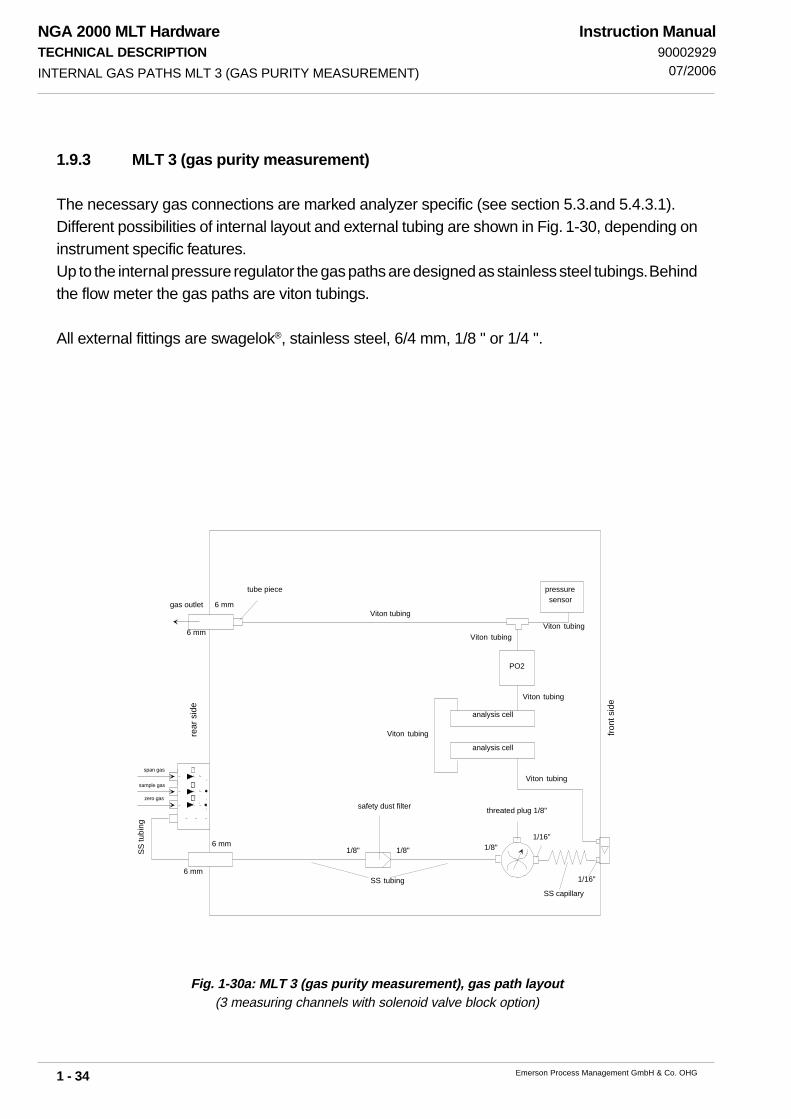
NGA 2000 MLT HardwareTECHNICAL DESCRIPTION
1 - 34 Emerson Process Management GmbH & Co. OHG
Instruction Manual90002929
07/2006
1.9.3 MLT 3 (gas purity measurement)
The necessary gas connections are marked analyzer specific (see section 5.3.and 5.4.3.1).Different possibilities of internal layout and external tubing are shown in Fig. 1-30, depending oninstrument specific features.Up to the internal pressure regulator the gas paths are designed as stainless steel tubings. Behindthe flow meter the gas paths are viton tubings.
All external fittings are swagelok®, stainless steel, 6/4 mm, 1/8 " or 1/4 ".
Fig. 1-30a: MLT 3 (gas purity measurement), gas path layout(3 measuring channels with solenoid valve block option)
front
sid
e
rear
sid
e
1/8"1/16"
1/16"
safety dust filter threated plug 1/8"
6 mm
6 mm
SS capillarySS tubing
SS tu
bing
Viton tubingViton tubing
6 mm
6 mmViton tubing
tube piece
Viton tubing
analysis cell
analysis cell
PO2
Viton tubing
Viton tubing
span gas
zero gas
sample gas
pressuresensorgas outlet
1/8" 1/8"
INTERNAL GAS PATHS MLT 3 (GAS PURITY MEASUREMENT)

NGA 2000 MLT HardwareTECHNICAL DESCRIPTION
1 - 35Emerson Process Management GmbH & Co. OHG
Instruction Manual9000292907/2006
Fig. 1-30c: MLT 3 (gas purity measurement), gas path layout(2 measuring channels with manual 4/2-way-valve option)
Fig. 1-30b: MLT 3 (gas purity measurement), gas path layout(3 measuring channels with solenoid valve block option and quick shuttoff connector option)
front
sid
e
rear
sid
e
1/8"1/16"
1/16"
safety dust filter
threated plug 1/8"
6 mm
6 mm
SS capillary
Viton tubing6 mm
6 mmViton tubing
tube piece
Viton tubing
analysis cell
analysis cell
Viton tubing
Viton tubing
6 mm
6 mm6 mm
6 mm SS tubing
4/2-
way
-val
vesample gas
span gas
zero gas
SS tubing
SS tubing
SS tubing
SS tubing
pressuresensorgas outlet
1/8" 1/8"
front
sid
e
rear
sid
e
1/8"
1/8"1/16"
1/16"
saftey dust filter
quick shutoffconnector
threated plug 1/8"
SS tubing
6 mm6 mm
6 mm
6 mm
SS capillary
SS tu
bing
SS tu
bing
Viton tubing
pressuresensor
Viton tubing6 mm
6 mmViton tubing
tube piece
Viton tubing
analysis cell
analysis cell
PO2
Viton tubing
Viton tubing
sample gas
span gas
zero gas
SS tubing
1/8" 1/8"
gas outlet
INTERNAL GAS PATHS MLT 3 (GAS PURITY MEASUREMENT)

NGA 2000 MLT HardwareTECHNICAL DESCRIPTION
1 - 36 Emerson Process Management GmbH & Co. OHG
Instruction Manual90002929
07/2006
1.10 Printed Circuit Boards
All necessary PCBs are pushed in into a cardcage, which is identically for all MLT versions (seeFig. 1-31).
Fig. 1-31a: Cardcage MLT 1/3/4, Top View
PRINTED CIRCUIT BOARDS
optional PCB(e.g. SIO / DIO)
MLT Rear Panel
Interconnection Board(ICB)
Network Inlet Module(LEM)
Cardcage
Controller Board (ACU)Signal Processing (PSV)
(free if using DSP)
Physical Interface (PIC)or
Digital Signal Processing (DSP)
MLT Front Side

NGA 2000 MLT HardwareTECHNICAL DESCRIPTION
1 - 37Emerson Process Management GmbH & Co. OHG
Instruction Manual9000292907/2006
1.10.1 ICB (Inter-Connection Board)
ICB is an interconnection board consisting of six 64-pin ICB bus slots to accommodate printedcircuit boards (PCB of Euro standard format).
1.10.2 PSV/PIC Combination
The PSV card (signal processing) carries out the A/D conversion and the real evaluation of eachmeasuring signal.The PIC card (Physics Interface Card, page 1-38) supplies the photometer components and theindividual sensors with the individual required operating voltages and transmits all measuringsignals to the signal processing unit PSV.
1.10.3 DSP (alternitavely to PSV/PIC Combination)
The DSP card (Digital Signal Processing) page 1-39) supplies the photometer components andthe individual sensors with the individual required operating voltages and carries out the A/Dconversion and the real evaluation of each measuring signal.
Fig. 1-31b: PCB arrangement MLT 2[Inside view, detail (without front panel)]
PRINTED CIRCUIT BOARDS
optional PCB[e.g. SIO / DIO]
Inter Connection Board(ICB)
Signal Processing(PSV)
(free if using DSP)
Controller Board(ACU)
Physical Interface (PIC)or
Digital Signal Processing (DSP)
Network Inlet Module(LEM, Option)

NGA 2000 MLT HardwareTECHNICAL DESCRIPTION
1 - 38 Emerson Process Management GmbH & Co. OHG
Instruction Manual90002929
07/2006
1.10.4 PIC (Physics Interface Card)
The PIC card (Physics Interface Card) supplies the photometer components and the individualsensors with the individual required operating voltages and transmits all measuring signals to thesignal processing unit PSV.
Fig. 1-32: Plug pin assignment PCB PIC
The plugs shown in Fig. 1-20 are used as follows:
Plug No. used
34 Chopper 1 (channel 1+2) 2 Chopper 2 (channel 3+4)47 Flow sensor 145 Flow sensor 220 Temperature sensor 1 (chopper 1)10 Temperature sensor 2 3 Source channel 4 4 Source channel 311 Source channel 212 Source channel 1 8 Detector channel 4 7 Detector channel 3 6 Detector channel 2 5 Detector channel 123 Detector channel 5 (O2 or H2)
Plug No. used
1 Pressure senor 1 9 Pressure senor 2
24 PCB OKI (P2) Flow sensor 3PCB OKI (P1) Flow sensor 4 (P1)
orPCB OKI (P4) Temperature sensor 3PCB OKI (P3) Temperature sensor 4
21.2 Testpeak channel 121.3 Ground ( )
PHYSICS INTERFACE CARD (PIC)
123
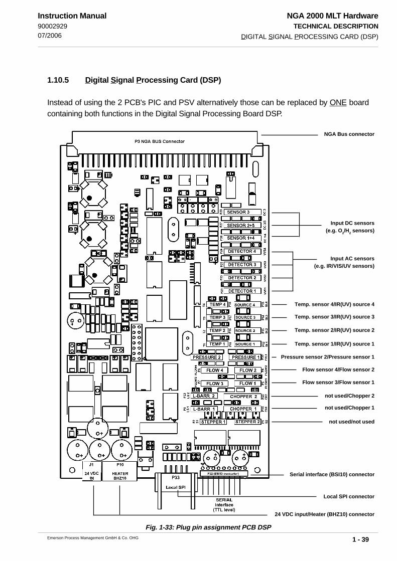
NGA 2000 MLT HardwareTECHNICAL DESCRIPTION
1 - 39Emerson Process Management GmbH & Co. OHG
Instruction Manual9000292907/2006
1.10.5 Digital Signal Processing Card (DSP)
Instead of using the 2 PCB's PIC and PSV alternatively those can be replaced by ONE boardcontaining both functions in the Digital Signal Processing Board DSP.
Fig. 1-33: Plug pin assignment PCB DSP
DIGITAL SIGNAL PROCESSING CARD (DSP)
NGA Bus connector
Input DC sensors(e.g. O2/H2 sensors)
Input AC sensors(e.g. IR/VIS/UV sensors)
Temp. sensor 4/IR(UV) source 4
Temp. sensor 3/IR(UV) source 3
Temp. sensor 2/IR(UV) source 2
Temp. sensor 1/IR(UV) source 1
Pressure sensor 2/Pressure sensor 1
Flow sensor 4/Flow sensor 2
Flow sensor 3/Flow sensor 1
not used/Chopper 2
not used/Chopper 1
not used/not used
Serial interface (BSI10) connector
24 VDC input/Heater (BHZ10) connector
Local SPI connector
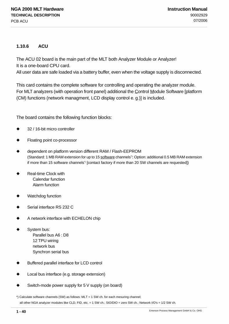
NGA 2000 MLT HardwareTECHNICAL DESCRIPTION
1 - 40 Emerson Process Management GmbH & Co. OHG
Instruction Manual90002929
07/2006PCB ACU
1.10.6 ACU
The ACU 02 board is the main part of the MLT both Analyzer Module or Analyzer!It is a one-board CPU card.All user data are safe loaded via a battery buffer, even when the voltage supply is disconnected.
This card contains the complete software for controlling and operating the analyzer module.For MLT analyzers (with operation front panel) additional the Control Module Software [platform(CM) functions (network managment, LCD display control e. g.)] is included.
The board contains the following function blocks:
32 / 16-bit micro controller
Floating point co-processor
dependent on platform version different RAM / Flash-EEPROM(Standard: 1 MB RAM extension for up to 15 software channels*); Option: additional 0.5 MB RAM extensionif more than 15 software channels*) [contact factory if more than 20 SW channels are requested])
Real-time Clock withCalendar functionAlarm function
Watchdog function
Serial interface RS 232 C
A network interface with ECHELON chip
System bus:Parallel bus A6 : D812 TPU wiringnetwork busSynchron serial bus
Buffered parallel interface for LCD control
Local bus interface (e.g. storage extension)
Switch-mode power supply for 5 V supply (on board)
*) Calculate software channels (SW) as follows: MLT = 1 SW ch. for each mesuring channel;
all other NGA analyzer modules like CLD, FID, etc. = 1 SW ch.; SIO/DIO = zero SW ch.; Network I/O's = 1/2 SW ch.

NGA 2000 MLT HardwareTECHNICAL DESCRIPTION
1 - 41Emerson Process Management GmbH & Co. OHG
Instruction Manual9000292907/2006
1.10.7 SIO (Standard Inputs-/Outputs)
Every platform, every MLT analyzer or every MLT analysis module can be equipped with max. 1SIO (see table P-1, too)!At mounting into a platform or an analyzer the SIO serves system functionallity of I/O´s andsupports all analysis modules of the NGA system.Only the analysis module itself is supported at mounting into an analysis module.To the programming we refer to the accompanying software instruction. The pin assigments aredescribed in section 21 of this instruction.
The SIO as standard consists of:
2 galvanically isolated analogous outputsSimultaneous 0(4) - 20 mA (± 22 mA, burden < 500 Ω) and
0(2) - 10 V (± 11 VDC, burden > 2 kΩ)
3 relay outputsLoad max. 30 V/1 A/30 W
1 serial interface (over extension card SIF)RS 232 (standard) or RS 485 (option, 2-wire or 4-wire)
Every SIO can be upgraded on 4, 6 or 8 analogous outputs via respective SIA modules with twoanalogous outputs each.
Fig. 1-34: Function blocks of SIO-PCB
SIO (STANDARD INPUTS-/OUTPUTS)
Analog output 1+2
Analog output 3+4 optionSIA
Analog output 5+6 optionSIA
Analog output 7+8 optionSIA
RS 232or RS 485
5 V DCsupply
NGA systembus interface
digital Functionand Autoconfiguration
Relayoutputs
Status LEDs
SIF

NGA 2000 MLT HardwareTECHNICAL DESCRIPTION
1 - 42 Emerson Process Management GmbH & Co. OHG
Instruction Manual90002929
07/2006
Fig. 1-35: SIO-PCB with extension cards
1.10.8 DIO (Digital In-/Outputs)
Every platform can be equipped with max. 1 to 5 DIOs. Every MLT analyzer or every MLT analysismodule can be equipped with max. 1-2 DIOs (see table P-1, too)!For maximum assembly with DIOs (5 or 2 DIOs resp.) there is no place for SIO PCB!At mounting into a platform or an analyzer the DIO serves system functionallity of I/O´s andsupports all analysis modules of the NGA system.Only the analysis module itself is supported at mounting into an analysis module.To the programming we refer to the accompanying software instruction. The pin assigments aredescribed in chapter 21 of this instruction.
On DIO PCB are integrated:
8 digital Inputs,5 - 30 VDC / 2,2 mALow level: 0,3 - 3,0 VDC / High level > 4 VDC
27 digital Outputs,5 - 30 VDC / max. 500 mA
DIO (DIGITAL IN-/OUTPUTS)
Posi
tion
of S
IA m
odul
eA
nalo
g ou
tput
5 +
6
Posi
tion
of S
IA m
odul
eA
nalo
g ou
tput
3 +
4
Posi
tion
of S
IA m
odul
eA
nalo
g ou
tput
7 +
8
Posi
tion
ofSI
F m
odul
eR
S232
or R
S485

NGA 2000 MLT HardwareTECHNICAL DESCRIPTION
1 - 43Emerson Process Management GmbH & Co. OHG
Instruction Manual9000292907/2006
1.11 Network Termination
The network module LEM (see Fig. 1-19) connects the analyzer with external modules via network.RJ 45 sockets are serving for network interconnection between analyzer or platform and analyzermodules (see Fig. 1-8, 1-13, 1-20, 1-23 and 1-31b).
It is necessary to terminate the ends of a twisted pair bus to minimize reflections (see Fig. 1-37).Failure to terminate the bus will degrade network performance.Termination will be done via RJ 45 connectors (see Fig. 1-36).
Fig. 1-36: RJ 45 network termination connector
Fig. 1-37: Network termination (examples)
NETWORK TERMINATION

NGA 2000 MLT HardwareTECHNICAL DESCRIPTION
1 - 44 Emerson Process Management GmbH & Co. OHG
Instruction Manual90002929
07/2006
Fig. 1-38: Analyzer Nameplate Label (example)
SPECIFICATIONS AT THE NAMEPLATE LABEL
1.12 Specifications at the Nameplate Label
The analyzer nameplate label gives important information about the instrument‘s configuration,installed measuring principle(s), sample gas(es) and measuring range(s).In case an instrument is built according a suitability approval the related certificate number is given,too.The nameplate label is located either on the instruments left or right housing side or at the inner sideof the front door (MLT 2).The CAT nameplate label is located at the housings left side whereat the label as it is shown belowis affixed to the inner analyzer module.
Model and installed measuringprinciples(here: MLT 4 Rackmounting,2 x IR, 2 x UV, 1 x PO2)
Channel 1:Gas and measuring range(here: CO, 60/600 ppm)
Serial number
International approval marks
Channel 2:Gas and measuring range(here: SO2, 26/260 ppm)
Channel 4:Gas and measuring range(here: NO2, 25/250 ppm)
Channel 4:Gas and measuring range(here: CO, 150/1,500 ppm)
Channel 5:Gas and measuring range(here: O2, 5/21 Vol-%)

NGA 2000 MLT HardwareTECHNICAL DESCRIPTION
1 - 45Emerson Process Management GmbH & Co. OHG
Instruction Manual9000292907/2006
All analyzer versions are marked as follows:
MLTx y-CH1 CH2 CH3 CH4 CH5with
x = analyzer type 1, 2, 3, 4, 5, CAT 200 with1 = 1/2 19", not thermostatted, external power supply2 = Field housing, thermostatted, internal power supply3 = 1/1 19"-housing, thermostatted, internal power supply4 = 1/1 19"-housing, thermostatted, external power supply5 = 19", 18 to 21 HU housing, thermostatted, internal power supplyCAT 200 = flameproof enclosure
y = analyzer version T, M, A, R, TE, ME, AE, RE withT = table topM = analyzer module, platform mounting
(net/electr. connections from front side only)A = analyzer module, external installation or platform mounting
(net/electr. connections from rear side or front side)R = rack mountingE = extended housing (MLT 1 only)
CH1...5 = measuring method of the individual (max. 5) measuring channels withIR = measurement at infrared spectral rangeUV = measurement at ultraviolet spectral rangeVIS = measurement at visual spectral rangePO
2 = paramagnetic oxygen measurement
EO2 = electrochemical oxygen measurementTC = thermal conductivity measurementTEO
2 = trace electrochemical oxygen measurement
SPECIFICATIONS AT THE NAMEPLATE LABEL

NGA 2000 MLT HardwareTECHNICAL DESCRIPTION
1 - 46 Emerson Process Management GmbH & Co. OHG
Instruction Manual90002929
01/2007
1.13 MLT 2HT (high temperature measurement)
As a special version MLT 2HT is available for measurements requiring physics thermostatedup to 120 °C. The physical compartment is parted into 2 sections:- A high temperature (HT) part with special heating and isolation for all components being incontact with sample gas - SS tubing/fittings, fine dust/safety filter, needle valve, calibrationvalve (depending on options). The heated lines are connected in the heated room with samplegas inlet and outlet fittings.- The isolation (filter) cell, chopper & detector are located in the lower physical part but outsideof the heated room (need protection from high temperature).The temperature controller is located in the upper electronical section.An optional external pump with heated pump head may be located outside of the analyzerbeing connected with heated samplegas lines (need of isolation at any connection/ fitting).
Temperature controllerin electronical section
Gas inlet/outlet fittings
Heated sectionwithSS tubing,safety filter andsample gas cell
Isolation cell,chopper & detector Isolated inlet for heated gas sampling line to beconnected te gas inlet and outlet fittings
Optional purgegas inlet
NGA 2000 MLT HardwareMEASURING PRINCIPLE
2 - 1Emerson Process Management GmbH & Co. OHG
Instruction Manual90002929
07/2006 IR MEASUREMENT
2. Measuring Principle
Depending on analyzer model different measuring methods will be used.
2.1 IR Measurement
The measuring effect devided from absorption of infrared radiation is due to the gas being
measured. The gas - specific wavelengths of the absorption bands characterize the type of gas
while the strength of the absorption gives a measure of the concentration of the component
measured. Due to a rotation chopper wheel, the radiation intensities coming from measuring and
reference side of the analysis cell produce periodically changing signals within the detector.
The detector signal amplitude thus alternates between concentration dependent and concentra-
tion independent values. The difference between the two is a reliable measure of the concentration
of the absorbing gas component.
The principle photometer assembly is shown in Fig. 2-1.

NGA 2000 MLT HardwareMEASURING PRINCIPLE
2 - 2 Emerson Process Management GmbH & Co. OHG
Instruction Manual90002929
07/2006IR MEASUREMENT
Fig. 2-1: Measuring Principle for NDIR / UV Measurement
8 Measuring side
9 Reference side
10 Filter cell without dividing wall
(for IFC measurement with optical filters)
11 Window
12 Pneumatic or pyroelectrical (solid-state) detector
13 VIS / UV semiconductor detector
14 Preamplifier
1 IR source with reflector
2 VIS / UV source with reflector
3 Chopper wheel
4 Eddy current drive
5 Filter cell with dividing wall (IR channel)
6 Filter cell with dividing wall (UV channel)
7 Analysis cell
11
3
2
4
6
7
1
5
7
8 8
99
10
11
10
13
14
12
14
to electronic
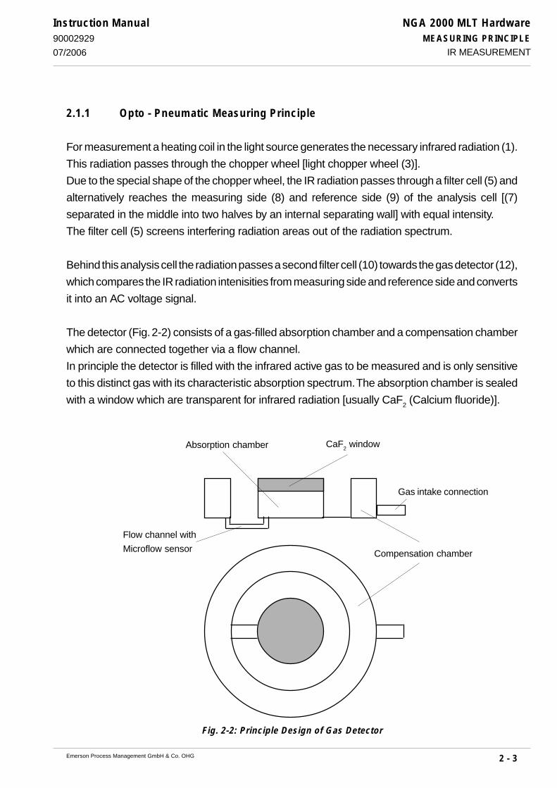
NGA 2000 MLT HardwareMEASURING PRINCIPLE
2 - 3Emerson Process Management GmbH & Co. OHG
Instruction Manual90002929
07/2006
2.1.1 Opto - Pneumatic Measuring Principle
For measurement a heating coil in the light source generates the necessary infrared radiation (1).
This radiation passes through the chopper wheel [light chopper wheel (3)].
Due to the special shape of the chopper wheel, the IR radiation passes through a filter cell (5) and
alternatively reaches the measuring side (8) and reference side (9) of the analysis cell [(7)
separated in the middle into two halves by an internal separating wall] with equal intensity.
The filter cell (5) screens interfering radiation areas out of the radiation spectrum.
Behind this analysis cell the radiation passes a second filter cell (10) towards the gas detector (12),
which compares the IR radiation intenisities from measuring side and reference side and converts
it into an AC voltage signal.
The detector (Fig. 2-2) consists of a gas-filled absorption chamber and a compensation chamber
which are connected together via a flow channel.
In principle the detector is filled with the infrared active gas to be measured and is only sensitive
to this distinct gas with its characteristic absorption spectrum. The absorption chamber is sealed
with a window which are transparent for infrared radiation [usually CaF2 (Calcium fluoride)].
Fig. 2-2: Principle Design of Gas Detector
IR MEASUREMENT
Gas intake connection
Absorption chamber CaF2 window
Compensation chamber
Flow channel with
Microflow sensor
NGA 2000 MLT HardwareMEASURING PRINCIPLE
2 - 4 Emerson Process Management GmbH & Co. OHG
Instruction Manual90002929
07/2006IR MEASUREMENT
When the IR radiation passes through the measurement side of the analysis cell into the detector,
a part of it is absorbed depending on gas concentration. Absorption chamber gas become colder,
gas pressure in the absorption chamber is reduced and some gas of compensation chamber
passes through the flow channel into the absorption chamber.
When the IR radiation passes through the reference side of the analysis cell into the detector, no
preabsorption occurs. Thus the gas inside the absorption chamber is heated, expands and some
of it passes through the flow channel into the compensation chamber.
The flow channel geometry is designed in such a way that it hardly impedes the gas flow by
restriction. Due to the radiation of chopper wheel, the different radiation intensities lead to
periodically repeated flow pulses within the detector.
The microflow sensor evaluates this flow and converts it into electrical voltages.
The electronics, which follow, evaluate the signals and convert them into the corresponding display
format.
In addition to simply light chopper, the chopper wheel has a special structure for measuring side
and reference side, that simulates an absorption in the analysis cell. This absorption signal is be
cut out of the normal measuring signal and is be used for automatically sensitivity control. The result
is a high long-term stability of sensitivity.
2.1.2 Interference Filter Correlation (IFC Principle)
The undivided analysis cell is alternately illuminated with filtered light concentrated in one of two
spectral separated wave length ranges. One of these two spectrally separated wave length bands
is chosen to coincide with an absorption band of the sample gas, and the other is chosen such
that none of the gas constituents expected to be encountered in practice absorbs anywhere within
the band.
The spectral transmittance curves of the interference filters used in the MLT and the spectral
absorption of the gases CO and CO2 are shown in Fig. 2-3. It can be seen that the absorption bands
of these gases each coincide with the passbands of one of the interference filters.

NGA 2000 MLT HardwareMEASURING PRINCIPLE
2 - 5Emerson Process Management GmbH & Co. OHG
Instruction Manual90002929
07/2006 IR MEASUREMENT
Fig. 2-3: Absorption Bands of Sample Gases and Transmittance of theInterference Filters used
The interference filter, used for generating a reference signal, has its passband in a spectral region
where none of these gases absorb. Most of the other gases of interest also do not absorb within
the passband of this reference filter.
The photometer assembly is similar to the assembly with “gas detector” (Fig. 2-1) with the
exception of the analysis cell. For analysis cell a non-sparated version is used. Behind this analysis
cell the radiation passes a second filter cell (10) to the pyroelectrical detector (12). In front of this
filter cell there are the individually optical filters.
The detector records the incoming IR radiation. This radiation will be reduced by the absorption
of the gas in the analysisi cell at this wavelength. The comparison between the measuring
wavelength and reference wavelength leads to an alternating voltage signal. This signal results
from cooling and heating the pyroelectrical material.
Wave Length [nm]
4400 460042004000 48003000 3200 3400 3600 3800 5000 5200 5400 5600 5800 6000
CO2
CO Interference
Filter
Absorption band
HC
CO2 CO
1836
5472
900
Tra
nsm
ittan
ce [%
]
9075
6045
3015
0
Tra
nsm
ittan
ce [%
]
Ref
eren
ce

NGA 2000 MLT HardwareMEASURING PRINCIPLE
2 - 6 Emerson Process Management GmbH & Co. OHG
Instruction Manual90002929
07/2006
2.2 UV Measurement
The absorption measurement in the UV spectral range is based on the same principle as the IR
measurement (Fig. 2-1).
A glow-discharge lamp [2] is used as radiation source.
The UV radiation passes through the chopper [3] and a filter cell [6] into the dual-section analysis
cell [7].
A second filter cell [6] is installed after the analysis cell. The photodetector [13], which follows,
converts the pulsating radiation intensities from measuring [8] and reference side [9] of the analysis
cell into electrical voltages.
As the glow-discharge lamp needs a specific and as constant as possible temperature, the UV
lamp is thermostatted to about 55 °C for MLT 1 or the lamp is built-in into a thermostatted ambiente
(MLT 2/3/4).
UV MEASUREMENT
NGA 2000 MLT HardwareMEASURING PRINCIPLE
2 - 7Emerson Process Management GmbH & Co. OHG
Instruction Manual90002929
07/2006
2.3 Oxygen Measurement
Depending on analyzer model different two measuring methods will be used.
2.3.1 Paramagnetic Measurement (PO2)
Oxygen measurement is based on the paramagnetical characteristics of Oxygen molecules:
Two nitrogen filled quartz spheres (N2 is not paramagnetic) are arranged in a dumbbell configuration
and, hinged to a platinum wire, placed inside a cell. Fixed to the wire a small mirror reflects a light
beam to a photo detector (fig. 2-4).
The measuring cell is placed inside an inhomogeneous magnetical field generated by a strong
permanent magnet of specific design.
Oxygen molecules within the sample gas now due to their paramagnetic characteristics are
deflected into the area of highest field strength. This generates different forces on both spheres and
the resulting torque turns dumbbell and mirror out of the rest position. This generates a photodetector
signal because the beam is deflected, too.
Initiated by the photodetector signal a preamplifier drives a compensation current through a loop
surrounding the dumbbell to turn back the dumbbell into the rest position by effect of a magnetic field
So the current compensating the torque affecting the dumbbell is a direct measure for the oxygen
concentration within the sample gas.
In addition to measuring cell, permanent magnet, electronics and enclosure the paramagnetic
oxygen detector contains a temperature sensor and a heating element to hold the detector at approx.
55 °C.
Several variations are available including corrosion resistant, solvent resistant and/or intrinsically
safe (for measuring flammable gases) versions.
OXYGEN MEASUREMENT

NGA 2000 MLT HardwareMEASURING PRINCIPLE
2 - 8 Emerson Process Management GmbH & Co. OHG
Instruction Manual90002929
07/2006OXYGEN MEASUREMENT
Fig. 2-4: Principle Construction of paramagnetic Analysis Cell
1 Permanentmagnet2 Platinum wire3 Mirror4 Glass ball5 Loop6 Photodetector7 Light source8 Preamplifier9 Display
10 Gas inlet11 Gas outlet
4 1 5 3 6 8
10 11 7 9
2

NGA 2000 MLT HardwareMEASURING PRINCIPLE
2 - 9Emerson Process Management GmbH & Co. OHG
Instruction Manual90002929
07/2006
Table 2-1: Solvent Resistant Sensor: Approved solvents
Table 2-2: Medium affected Materials within Paramagnetic Oxygen Sensor
OXYGEN MEASUREMENT
Solvent-resistant Paramagnetic Oxygen Cell Solvents being tested: up to 20% Name Name Name Name Name Acetone Propane Methanol Carbon dioxide Toluene Acrolein n-Butane Ethylene Dimethyl sulfide Benzene Argon Pentane Ethylene oxide Dimethyl ether Vinyl acetate Aromatics Hexane Acetylene Hydrogen Vinyl acetylene Butadiene Heptane Butene Propadiene Xylene Butadiene-1 Methyl bromide i Butyr acid Cyclohexane Methyl ethyl ketone Butadiene-2 Iso propanol i-Butyr aldehyde Cyclohexanone Methyl acetate Methane Acetic acid i-Propyl formiat Propylene Methyl kaptane Ethane Ethanol Formaldehyde Propylene oxide Conditions: The maximum concentrations need not to exceed 20% as single or sum values! Assumption: a sample gas cooler lowers the dew point to approx. 5 °C. A solvent resistant measuring cell is a consumable part!
Chlorine-resistant Paramagnetic Oxygen Cell Components being tested: Name Chlorine (dry) up to 99% Dichloroethyle up to 20%

NGA 2000 MLT HardwareMEASURING PRINCIPLE
2 - 10 Emerson Process Management GmbH & Co. OHG
Instruction Manual90002929
07/2006
Special Hints on Paramagnetical Oxygen Sensors
The table below shows how accompanying gases interfere the paramagnetic oxygen measure-
ment.
If the concentration of such gases is already given at time of enquiry this interference may be taken
into account during factory startup and thus minimized (option).
Table 2-3: Paramagnetic Oxygen Measurement,cross interference by accompanying gases
OXYGEN MEASUREMENT

NGA 2000 MLT HardwareMEASURING PRINCIPLE
2 - 11Emerson Process Management GmbH & Co. OHG
Instruction Manual90002929
07/2006
2.3.2 Electrochemical Measurement (EO2)
This sensor uses the principle of galvanic cells, fig. 2-5 shows the design.
Fig. 2-5: Structure of electrochemical Oxygen Sensor
The electrochemical oxygen sensor‘s key components are a lead anode (1) and a gold cathode
(2) surrounded by a special acid electrolyte (3).
The gold electrode is integrated solid with the membrane,which is a non-porous fluororesin
membrane. Oxygen which barely diffuses through the membrane is electrochemically reduced on
the gold electrode.
The temperature compensating thermistor and adjusting resistance are connected between the
cathode and anode. The current generated by oxygen reduction is converted into a voltage by
these resistances.
The value of the current flowing to the thermistor and resistance varies in proportion to the oxygen
concentration of the measuring gases which contact the membrane. Therefore, the voltage at the
terminal of the resistances is used for the sensor output to measure the oxygen concentration.
OXYGEN MEASUREMENT
12
9
8
4
10
1
6
5
7
3
11
2
12
11
13

NGA 2000 MLT HardwareMEASURING PRINCIPLE
2 - 12 Emerson Process Management GmbH & Co. OHG
Instruction Manual90002929
07/2006
Fig. 2-6: Reaction of galvanic cell
In consequence of it‘s design the sensor‘s lifetime is limited and depends on theoretical designed
life and oxygen concentration. The sensor output can be taken as a rough criterion for end of
lifetime: The sensor is weared when the output in atmosphere is below 70 % of the initial output.
The period till this can be calculated by
The sensor‘s designed life under constant conditions of 20 °C is approx. 900,000 hrs.
The lifetime at 21 % oxygen is then calculated to approx. 42,857 hrs, corresponding to approx.
5 years.
The given values are for reference only! The expected lifetime is greatly affected by the temperatureof the environment in which the sensor is used or stored. Increases or decreases in atmosphericpressure have the same effect as that by increases or decreases in oxygen concentration (Opera-tion at 40 °C halves lifetime).
Notes for analyzers with electrochemical EO2 cell!This sensor is not suitable for anorganic gases containing chlorene or flourene!In addition is not suitable for sample gases containing ozone, H
2S (> 100 ppm) or
NH3 (> 20 ppm).Due to the measuring principle the electrochemical oxygen cell requires a minimum internal consumptionof oxygen (residual humidity avoids drying of the cell). Supplying cells continuously with dry sample gasof low grade oxygen concentration or with sample gas free of oxygen could result in a reversible detuningof O2 sensitivity. The output signal will become instable, but response time remains constant.For correct measurement the cell needs continuously to be supplied with concentrations of at least 0.1 Vol.-% O2 . We recommend to use the cells if need be in alternating mode, means to purge cells with conditioned(not dried, but dust removed) ambient air when measurement pauses.If it is necessary to interrupt oxygen supply for several hours or days, the cell has to regenerate (supplycell for about one day with ambient air). Temporary flushing with nitrogen (N2) for less than 1 h (e.g. foranalyzer zeroing purpose) has no influence on measuring characteristics.
designed life (hours)O2 concentration (%)
Lifetime =
OXYGEN MEASUREMENT
Resistor (6)Thermistor (5)
(11)(Red) (Black)
(+)
Lead-
Anode (1)
(-)
Gold-
Cathode (2)
Summary reaktion O2 + 2 Pb → 2 PbO
Electrolyte (3)
(ph 6)
2 Pb + 2 H2O → 2 PbO + 4 H+ + 4 e-O
2 + 4 H+ + 4 e- → 2 H
2O
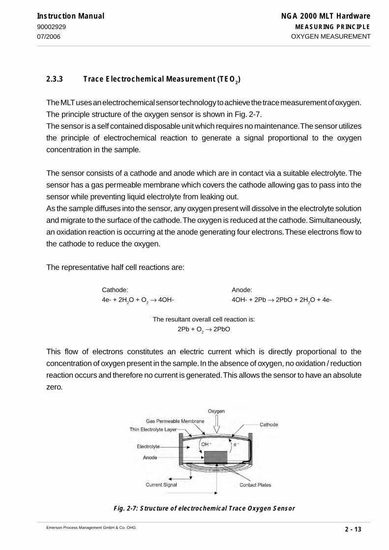
NGA 2000 MLT HardwareMEASURING PRINCIPLE
2 - 13Emerson Process Management GmbH & Co. OHG
Instruction Manual90002929
07/2006
2.3.3 Trace Electrochemical Measurement (TEO2)
The MLT uses an electrochemical sensor technology to achieve the trace measurement of oxygen.
The principle structure of the oxygen sensor is shown in Fig. 2-7.
The sensor is a self contained disposable unit which requires no maintenance. The sensor utilizes
the principle of electrochemical reaction to generate a signal proportional to the oxygen
concentration in the sample.
The sensor consists of a cathode and anode which are in contact via a suitable electrolyte. The
sensor has a gas permeable membrane which covers the cathode allowing gas to pass into the
sensor while preventing liquid electrolyte from leaking out.
As the sample diffuses into the sensor, any oxygen present will dissolve in the electrolyte solution
and migrate to the surface of the cathode. The oxygen is reduced at the cathode. Simultaneously,
an oxidation reaction is occurring at the anode generating four electrons. These electrons flow to
the cathode to reduce the oxygen.
The representative half cell reactions are:
Cathode: Anode:
4e- + 2H2O + O
2 → 4OH- 4OH- + 2Pb → 2PbO + 2H
2O + 4e-
The resultant overall cell reaction is:
2Pb + O2 → 2PbO
This flow of electrons constitutes an electric current which is directly proportional to the
concentration of oxygen present in the sample. In the absence of oxygen, no oxidation / reduction
reaction occurs and therefore no current is generated. This allows the sensor to have an absolute
zero.
Fig. 2-7: Structure of electrochemical Trace Oxygen Sensor
OXYGEN MEASUREMENT

NGA 2000 MLT HardwareMEASURING PRINCIPLE
2 - 14 Emerson Process Management GmbH & Co. OHG
Instruction Manual90002929
07/2006
Notes for analyzers with electrochemical TEO2 cell!For TEO2 sensor please note that the gas inlet and outlet connections of the analyzer are sealed to prevent
exposure of the sensor to air.
Prolonged exposure of the sensor to air can cause extended start up time, reduction of performance or
damage to the sensor. Do not remove the sealing caps until all associated sample handling components
are installed and the instrument is fully ready for installation.
After replacement purge gas paths with inert gas (nitrogen (N2)) or sample gas as soon as possible to avoid
prolonged exposure of the sensor to high concentrations of oxygen.
The longer the sensor is exposed to air, the longer it will take for the sensor to recover to low ppm levels.
When installing a new sensor or starting the instrument for the first time, it may take as long as eight hours
for the analyzer to purge down to the lowest operating range.
Prolonged exposure of the sensor to air can cause extended start up time, reduction of performance or
damage to the sensor.
After initial startup or startup following a prolonged shutdown, the analyzer may require extended time to
recover to the range of measurement. Commonly, this is caused by the introduction of ambient air into the
sample and/or vent lines to the sensor. The presence of higher than normal levels of oxygen at the sensor
will cause the sensor electrolyte to become saturated with dissolved oxygen. When the instrument is placed
in operation, the sensor must now consume all excess dissolved oxygen above the desired measuring
level.
All analyzers with electrochemical TEO2 cell have to be purged with inert gas (Nitrogen, N2) prior to
disconnect the gas lines ! Then the gas line fittings have to be closed for transport or depositing analyzer.
OXYGEN MEASUREMENT

NGA 2000 MLT HardwareMEASURING PRINCIPLE
2 - 15Emerson Process Management GmbH & Co. OHG
Instruction Manual90002929
07/2006
2.4 Thermal Conductivity
To measure gases like Hydrogen (H2), Argon (Ar) or Helium (He), the measurement method of
thermal conductivity (TC) will be used.
2.4.1 Sensor Design
A complete in glass encapulated temperature resistor is the basis of the measuring.
Four of this resisitors are arranged in a Wheatstone Bridge which is mounted into a block. The block
itself is thermostatted to supress influence of external temperature change.
2.4.2 Analysis Cell
Both the cell volume and the mass of its measurement resistor have been minimized in order to
obtain short response time.
The block contains two gas paths for sample and reference gas. Always two sensors are
located in the sample and the reference gas path.
Depending on application the reference side either is closed gastight and optional filled with
reference gas or it is opened and can be purged with reference gas (corresponding to the
respective measuring application).
Materials in contact with sample gas are aluminum, Viton, glass and gold in the standard type.
Measuring cells stand for corrosive applications, block and tubing are of SiO2 coated stainless steel
or from Hastelloy according to the measuring application.
Fig. 2-8: Sensor block (thermal conductivity detector TCD)
THERMAL CONDUCTIVITY

NGA 2000 MLT HardwareMEASURING PRINCIPLE
2 - 16 Emerson Process Management GmbH & Co. OHG
Instruction Manual90002929
07/2006
2.4.3 Measurement Method
The entire measurement cell is thermostated to a temperature of up to 75 °C. The four integral
temperature sensors are electrically heated to a higher temperature. Their temperatures, and thus
their electrical resistance, are dependent upon heat losses, which, in turn, result from heat
transport in the surrounding gas to colder chamber walls. For otherwise stable conditions, this heat
transport will be proportional to the thermal conductivity of the gas present between the sensor
and the chamber wall. Interconnecting the four sensors into Wheatstone bridge circuit (Fig. 2-9)
provides an electronic signal proportional to gas density. Electronic circuitry processes this signal
to obtain standardized signal amplitudes, and transmits these to both an indicator instrument and
to the signal output connector.
The internal gas paths are constructed to get a minimimized response time at minimized
dependence of the analytical signal upon sample gas flow rate.
THERMAL CONDUCTIVITY
Fig. 2-9: Measuring principle Thermal Conductivity Sensor (Wheatstone bridge)
DC voltage supply
Display(Vol.-%)
RmeasureRreference
Rmeasure Rreference

NGA 2000 MLT HardwareINSTALLATION
5 - 1Emerson Process Management GmbH & Co. OHG
Instruction Manual9000292907/2006
EXPLOSION HAZARD !Do not operate nor install these instruments in hazardous areaswithout additional measures!
ELECTRICAL SHOCK HAZARD!Prior to connecting the analyzer to mains ensure all safety instructionsas given in the appropriate chapter at the beginning of this manual andin the following analyzer refered sections are read and unterstood!
Installation area has to be clean, free frommoisture, excessive vibration and frost-protected. Take care to meet the permissibleambient temperatures as given in thetechnical data section!
Instruments must not be exposed to directsunlight, fluorescent lamps nor sources ofheat.
For suppressed ranges of MLT 3 for gaspurity measurment we recommend installa-tion between 20 °C and 30 °C ( 68 to 86 °F).
For outdoor installation it is recommendedto mount the instruments into a cabinet. Atleast sheltering against rain is required.
Do not cover venting openings and take careto mount the instrument in a distance to wallsnot affecting venting.
5. Installation
This chapter describes in detail how to install the different analyzer variations.
5.1 General
Carefully examine the shipping carton and contents for signs of damage.Immediately notify the shipping carrier if the carton or its contents are damaged.Retain the carton and packing material until the instrument is operational.
GENERAL

NGA 2000 MLT HardwareINSTALLATION
5 - 2 Emerson Process Management GmbH & Co. OHG
Instruction Manual90002929
07/2006GENERAL
To stay in compliance with regulations regarding electromagnetic compatibility it is recommendedto use only shielded cables, as optionally available from Emerson Process Management orequivalent. Customer has to take care that the shield is connected in proper way. Shield and signalconnector enclosure need to be conductively connected, submin-d-plugs and sockets must bescrewed on the analyzer.
Using external submin-d-to-terminal adaptor elements (option) affects electromagnetic compat-ibility. In this case the customer has to take measures to stay in compliance and has to declareconformity, when required by legislation (e.g. European EMC Directive).
The mains socket has to be nearby the power supply unit and easilyaccessible! Disconnecting from mains requires unplugging the power plug!To comply with the CE mark requirements, analzyers requiring DC powersupply must be supplied by a power supply unit of type UPS 01 T, DP 157,SL5, SL10 (DP 157 rack installation only) or equivalent units. Equivalentunits must provide SELV output voltages!Verify proper polarity when connecting DC 24 V operated analyzers !

NGA 2000 MLT HardwareINSTALLATION
5 - 3Emerson Process Management GmbH & Co. OHG
Instruction Manual9000292907/2006
TRANSFER SAFETY LOCK !First of all operations unscrew transfer safety lock of MLT 1/ULCO or MLT 2 !MLT 1/ULCO: Unscrew both knurled-head screws on bottom side of the housing(Fig. 5-1a) ! For protection against loss screw the knurled-head screws intothe respective holders at housing rear side (Fig. 5-1b) !MLT 2: Unscrew transfer safety lock of photometer sliding carriage (Fig. 5-1c)!For transport of MLT the transfer safety lock absolutely have to be locked !
5.1.1 Transfer Safety Lock of MLT 1/ULCO or MLT 2
TRANSFER SAFETY LOCK OF MLT 1/ULCO OR MLT 2
Fig. 5-1a: Transfer safety lock MLT-ULCO(housing side view, detail sketch)
Fig. 5-1b: MLT 1, Rear panel (holder for safety lock)
Fig. 5-1c: MLT 2, Photometer safety lock
Transfer safety lock (two knurled-head screws)
Front panel

NGA 2000 MLT HardwareINSTALLATION
5 - 4 Emerson Process Management GmbH & Co. OHG
Instruction Manual90002929
07/2006
5.2 Gas Conditioning (Sample Handling)
To ensure trouble-free analyzer operation one has to attach great importance to gas conditioning:
All gases must be conditioned before supplying!When supplying corrosive gases ensure that gas path components are notaffected!!
Flammable gases must not supplied without additional protective measures!It is prohibited to supply explosive gases!
Furthermore the gases must be dry free of dust free of aggressive components affecting gas path materials (e.g. by corrosion).
If moisture can not be avoided take care that the gas‘ dew point is at least 10 °C below ambienttemperature to avoid condensation within the gas path.Pressure and flow have to be within the limits given in the technical data section.For suppressed ranges a constant pressure (+- 1 psig at 20 - 25 psig) and constant temperature(20 - 30 °C, 68 - 86 °F) are very important.
Suitable gas conditionning hardware may be supplied or recommended for specific analyticalproblems and operating conditions.
GAS CONDITIONING (SAMPLE HANDLING)

NGA 2000 MLT HardwareINSTALLATION
5 - 5Emerson Process Management GmbH & Co. OHG
Instruction Manual9000292907/2006
5.2.1 Fine Dust Filter (Option MLT 3)
MLT 3 can have two built-in fine dust filters (filter material PTFE, pore-size approx. 2 µm) optional.
5.2.2 Gas Sampling Pump (Option MLT 3)
Optional MLT 3 can be equipped with a gas sampling pump (pumping rate max. 2.5 l/min.).
Note!For mobile application of MLT only !Lifetime max. 5,000 running hours !
5.2.3 Pressure Sensor (Option)
It is possible to integrate a pressure sensor with a range of 800 - 1100 hPa.The concentration values computed by the analyzer will then be corrected to reflect the barometricpressure to eliminate faulty measurements due to changes in barometric pressure (see technicaldata).
5.2.4 Gas Flow
The gas flow rate should be within the range 0.2 l/min to maxi. 1.5 l/min !
A constant flow rate of about 1 l/min is recommended.
The gas flow rate for MLT with paramagnetic oxygen sensor (PO2),trace electrochemical oxygen sensor (TEO2) and for MLT 2 analyzers usedin hazardous area (Ex zones) is allowed to max. 1.0 l/min !
It is possible to integrate a flow sensor with a range 0 - 2 l/min ( 0.2 l/min to maxi. 1.5 l/minrecommended) ! In this case gas flow can be shown via operation front panel.For MLT 3 flow control can be done with a screw driver via a optional integrated throttle into theoptional built-in dust filter.
GAS CONDITIONING (SAMPLE HANDLING)

NGA 2000 MLT HardwareINSTALLATION
5 - 6 Emerson Process Management GmbH & Co. OHG
Instruction Manual90002929
07/2006GAS CONNECTIONS
TOXIC GAS HAZARDS!Take care that all external gas lines are connected as described and aretight to avoid leaks!Improperly connected gas lines may cause explosion or death!Exhaust may contain hydrocarbon and other toxic components (e.g. carbonmonoxide)! Carbon monoxide is highly toxic and can cause headache,nausea, loss of consciousness, and death. Avoid inhalation of exhaust!
Take care of the safety instructions applicable for the gases (samplegases and test gases) and for the gas bottles containing these gases!
Flammable gases must not supplied without additional protectivemeasures!It is prohibited to supply explosive gases!
5.3 Gas Connections
Do not interchange gas inlet and outlet! All gases must be conditioned beforesupplying! When supplying corrosive gases ensure that gas path components arenot affected!
Max. permissible gas pressure: 1,500 hPa, except instruments for gas puritymeasurement (see chapter 5.4.3.1), with integrated valve blocks (see page 5-8)and/or paramagnetic Oxygen sensor (see table page 20-4)!
Exhaust lines must be installed in a descending way, need to be pressureless,frost-protected and in compliance with applicable legislative requirements!

NGA 2000 MLT HardwareINSTALLATION
5 - 7Emerson Process Management GmbH & Co. OHG
Instruction Manual9000292907/2006
The number of gas fittings as well as their assignment vary depending on analyzer model andselected options.All gas fittings are labeled and are normally located at the analyzers rear panel, in case of MLT2 and CAT 100 they are located at the bottom side.When it is necessary to open gas paths seal the analyzer‘s gas fittings by using PVC caps to avoidpollution of the internal gas path by moisture, dust, etc.
The analyzer should be mounted near the sample source to minimize sample transport time. Asample pump may be used to descrease response time, whereat the analyzer is either operatedin bypass mode or protected by an overpressure valve against too high flow and pressure (seefig. 5-2).
Fig. 5-2: MLT, Bypass installation
GAS CONNECTIONS
Overpressure valve
Flow meter
Exhaust
ExhaustMLT
Gas sampling pump
Filter

NGA 2000 MLT HardwareINSTALLATION
5 - 8 Emerson Process Management GmbH & Co. OHG
Instruction Manual90002929
07/2006
5.3.1 Internal Solenoid Valve Block (Option for MLT 1/CAT 200)
For operation with optional solenoid valves, the following indications have to be considered:Operation with solenoid valves is not possible for 2 - channel analyzer with parallel gas paths.Supply overpressure for all gases is limited to 50 to 500 hPa when an analyzer is equipped withan internal solenoid valve block. .
5.3.2 Purge Gas Connections
The analyzers may optionally provide a gas fitting for purging the enclosure (e.g. with nitrogen)when measuring low CO
2 concentrations:
N2 minimizes interference by ambient air
flammable gases:N
2 gives additional safety in the event of leakage inside the instrument
aggressive components:purging with air gives additional safety in the event of leakage inside the instrument.
Purge medium must be dry, clean and free of corrosive and solventcomponents!
Purging can be accomplished with any inert gas including "instrument quality" air, nitrogen, orargon which contains no more than trace amounts of a combustible vapor. Compressed air is themost common and practical purging medium. Bottled nitrogen is uitilized most frequently inisolated places where no compressed air source is available. Personal protection has to be takeninto consideration in case of N
2 purge in closed rooms, e.g. containers.
Purge gas must be conditioned:Take care for purge gas temperature: Purge gas should have the same temperatureas ambient temperature of the analyzer but NOT below 20 °C and above 35 °C!Otherwise it must be cooled or warmed up before let in into the instrument!Purge gas should be instrumental / synthetic air (free of oil, no corrosive, toxicor flammable gas componets) or nitrogen depending on application.
GAS CONNECTIONS

NGA 2000 MLT HardwareINSTALLATION
5 - 9Emerson Process Management GmbH & Co. OHG
Instruction Manual9000292907/2006
5.4 Analyzer Specific Instructions
5.4.1 MLT 1
5.4.1.1 MLT 1, platform mounting only
MLT 1 analyzer module housing is available for platform mounting (built-in into a NGA platform)only (type M).These analyzers need DC 24 V power supply and netwotk connection utilizing platform. Built-inthe modul into platform housing correctly (see platform manual).Switching On the module will be done via Switching On the platform.
Output signals and data are accessible at the rear panel via submin-d connectors. Depending onanalzyer variation not all signals are available. For information about pin-assignments see section21.
ANALYZER SPECIFIC INSTRUCTIONS: MLT 1
Fig. 5-3: MLT 1 analysis module (platform mounting), front panel, front view
Network
24 V dcIN

NGA 2000 MLT HardwareINSTALLATION
5 - 10 Emerson Process Management GmbH & Co. OHG
Instruction Manual90002929
07/2006
5.4.1.2 MLT 1, external installation and 1/2-19" Housing
MLT 1 analyzer module housing is available for platform mounting (built-in into a NGA platform)or for external installation (type A).
The analyzer variation MLT 1 configured as tabletop analyzer (type T) provide a handle attachedto a front panel frame. The instrument is intended for horizontal or slightly angular (utilizing thehandle as support) orientation during operation.Without front panel frame and handle the analyzers may be mounted into a rack (rack mountversion, type R). Four screws located at the front panel are used to fix the analyzer in the rack.
These analyzers need DC 24 V power supply utilizing an external power supply unit. They providea three pole power input connector located at the rear panel.
It is recommended to use original Emerson Process Management powersupply units and supply cords. If a supplement is used take care of correctpin assignment, as given on the analyzer´s rear panel!
The analyzers do not provide a power switch and are operable when con-nected to power.
For analyzer module (A) [external installation or platform mounting] it isnot allowed to supply the module from front and rear simultaneously !For external installation connections on frontside absolutely have to closedwith the blind plate delivered from our factory to be in agreement with theCE conformity.!
Output signals and data are accessible at the rear panel via submin-d connectors. Depending onanalzyer variation not all signals are available. For information about pin-assignments see section21.
ANALYZER SPECIFIC INSTRUCTIONS: MLT 1
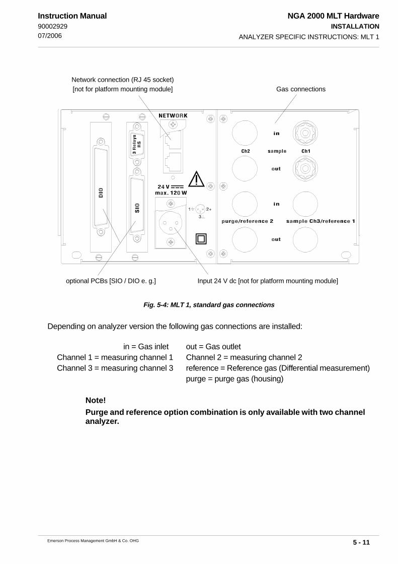
NGA 2000 MLT HardwareINSTALLATION
5 - 11Emerson Process Management GmbH & Co. OHG
Instruction Manual9000292907/2006
Fig. 5-4: MLT 1, standard gas connections
Depending on analyzer version the following gas connections are installed:
in = Gas inlet out = Gas outletChannel 1 = measuring channel 1 Channel 2 = measuring channel 2Channel 3 = measuring channel 3 reference = Reference gas (Differential measurement)
purge = purge gas (housing)
Note!Purge and reference option combination is only available with two channelanalyzer.
ANALYZER SPECIFIC INSTRUCTIONS: MLT 1
Network connection (RJ 45 socket)[not for platform mounting module] Gas connections
Input 24 V dc [not for platform mounting module]optional PCBs [SIO / DIO e. g.]

NGA 2000 MLT HardwareINSTALLATION
5 - 12 Emerson Process Management GmbH & Co. OHG
Instruction Manual90002929
07/2006
Fig. 5-5: MLT 1, gas connections with solenoid valve option
V 1 = Span gas 1V 2 = Span gas 2V 3 = Sample gasV 4 = Zero gasout = Gas outlet (to IN CH1)*
IN CH1 = Gas input (from OUT of soelnoid valve block)*OUT CH1 = Gas exhaust
* Standard.Option: Valve block output may be sued for external sample handling system (special configura-tion)
ANALYZER SPECIFIC INSTRUCTIONS: MLT 1
Solenoid valve block

NGA 2000 MLT HardwareINSTALLATION
5 - 13Emerson Process Management GmbH & Co. OHG
Instruction Manual9000292907/2006
5.4.2 MLT 2 (Field Housing)
The MLT 2 variation is designed for wall mounting and is available in two different versions: Oneversion, equipped with standard front panel is intended to be installed at protected locationswhereas the version with impact tested magnetically operated front panel may be outdoorinstalled.In any case the restrictions for ambient temperatures have to be taken into account, see sectiontechnical data!
This current instruction manual covers using the MLT 2 analyzer for generalpurpose applications only!
Installation, startup and maintenance for operation in hazardous areas aredescribed in detail in a separate instruction manual, shipped together witheach such analyzer and are not subject of the current instruction manual!
5.4.2.1 Wall Mounting
This housing is designed for wall mounting.Utilizing the four mounting brackets at the analyzer‘s rear side the instrument can be wall mounted.For fastening points see Fig. 5-6 please.
MLT 2 -- HEAVY INSTRUMENTS !The analyzer variations MLT 2 intended to be wall mounted and/or outdoorinstalled weigh up to 35 kg, depending on included options!Use two person and/or suitable tools for transportation and lifting theseinstruments!Take care to use anchors and bolts specified to be used for the weight ofthe units!Take care the wall or stand the unit is intended to be installed at is solidand stable to hold the units!
ANALYZER SPECIFIC INSTRUCTIONS: MLT 2
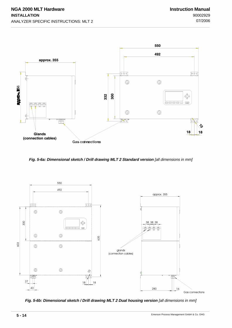
NGA 2000 MLT HardwareINSTALLATION
5 - 14 Emerson Process Management GmbH & Co. OHG
Instruction Manual90002929
07/2006
Fig. 5-6a: Dimensional sketch / Drill drawing MLT 2 Standard version [all dimensions in mm]
Fig. 5-6b: Dimensional sketch / Drill drawing MLT 2 Dual housing version [all dimensions in mm]
ANALYZER SPECIFIC INSTRUCTIONS: MLT 2
Gas connections
glands(connection cables)
approx. 355
1818
43
27
603
635
550
492
300 38 3838
280 16
10

NGA 2000 MLT HardwareINSTALLATION
5 - 15Emerson Process Management GmbH & Co. OHG
Instruction Manual9000292907/2006
5.4.2.2 Electrical Connections
Cables entering the analyzer housing should be kept as short as possible inside theenclosure.
The cable glands are suitable to fix cables with outer diameters of 7 to 12 mm. Specialadaptors are available for fixing other or multiple cables in one gland.
Mains terminals are designed to connect wires up to a cross section of up to 2,5 mm². To ensure electromagnetic compatibility it is recommended to use shielded signal cables
only!Take into account the installation instructions for cable glands (page 5-19)!
ELECTRICAL SHOCK HAZARD!Installation and connecting mains and signal cables are subject to qualifiedpersonnel only taking into account all applicable standards and legislativerequirements!Failure to follow may cause warranty invalidation, property damage and/orpersonal injury or death! Mains and signal cables need to be connected tointernal srew terminals requiring to work at open housing near life parts!Installation of this instrument is subject to qualified personnel only, familiarwith the resulting potential risks!MLT 2 gas analyzers do not provide a mains switch! A mains switch orcircuit breaker has to be provided in the building installation. This switchhas to be installed near by analyzer, must be easily operator accessible andhas to be assigned as disconnector for the analyzer.The analyzer provides a protective earth terminal. To prevent electrical shockhazards the instrument must be connected to a protective earth. Thereforethe instrument has to be connected to mains by using a three wire mainscable with earth conductor!Any interruption of the earth connector inside or outside the instrument ordisconnecting the earth terminal may cause potential electrical shockhazzard!The analyzer does not provide a mains switch and is operable whenconnected to power.
ANALYZER SPECIFIC INSTRUCTIONS: MLT 2
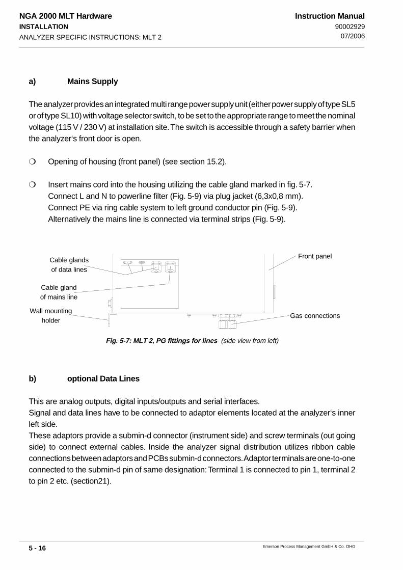
NGA 2000 MLT HardwareINSTALLATION
5 - 16 Emerson Process Management GmbH & Co. OHG
Instruction Manual90002929
07/2006
a) Mains Supply
The analyzer provides an integrated multi range power supply unit (either power supply of type SL5or of type SL10) with voltage selector switch, to be set to the appropriate range to meet the nominalvoltage (115 V / 230 V) at installation site. The switch is accessible through a safety barrier whenthe analyzer‘s front door is open.
Opening of housing (front panel) (see section 15.2).
Insert mains cord into the housing utilizing the cable gland marked in fig. 5-7.Connect L and N to powerline filter (Fig. 5-9) via plug jacket (6,3x0,8 mm).Connect PE via ring cable system to left ground conductor pin (Fig. 5-9).Alternatively the mains line is connected via terminal strips (Fig. 5-9).
Fig. 5-7: MLT 2, PG fittings for lines (side view from left)
b) optional Data Lines
This are analog outputs, digital inputs/outputs and serial interfaces.Signal and data lines have to be connected to adaptor elements located at the analyzer‘s innerleft side.These adaptors provide a submin-d connector (instrument side) and screw terminals (out goingside) to connect external cables. Inside the analyzer signal distribution utilizes ribbon cableconnections between adaptors and PCBs submin-d connectors. Adaptor terminals are one-to-oneconnected to the submin-d pin of same designation: Terminal 1 is connected to pin 1, terminal 2to pin 2 etc. (section21).
ANALYZER SPECIFIC INSTRUCTIONS: MLT 2
Gas connections
Front panel
Wall mountingholder
Cable glandof mains line
Cable glandsof data lines

NGA 2000 MLT HardwareINSTALLATION
5 - 17Emerson Process Management GmbH & Co. OHG
Instruction Manual9000292907/2006
Cables for external data processing must be double insulated for mainsvoltage when used inside the instrument!If double insulation not possible signal cables inside the analyzer must beinstalled in a way that a distance of at least 5 mm is ensured permanently(e.g. by utilizing cable ties).
The number of installed adaptor elements variies depending on analyzer configuration.For detailed pin designations see section 21.
Opening of housing (front panel) (see section 15.2).
Take lines via cable glands (Fig. 5-7) inside the housing.Connection is to be done to the respective adaptor elements (Fig. 5-8 and 5-9).
All unused cable glands need to be sealed using a sealing plug (part no.ETC00791 or similiar, see Fig. 5-11).Unused cable gland openings in the enclosure need to be covered using aspecial screw (part no. ETC 000790 or similiar, see Fig. 5-11).
ANALYZER SPECIFIC INSTRUCTIONS: MLT 2
Fig. 5-8: MLT 2, Data line connectionsInside view from front (detail, without front door)
21
X11X9
1 1
Adaptor element option SIO:Option serial interface /
Relay contacts (NAMUR)
Adaptor element option SIO:analog outputs
Adaptor element Option DIO:digital inputs/outputs
Power supply(s)

NGA 2000 MLT HardwareINSTALLATION
5 - 18 Emerson Process Management GmbH & Co. OHG
Instruction Manual90002929
07/2006GAS CONNECTIONS
Fig. 5-9: MLT 2, Connection data lines / mains line(inside view, left side panel)
ANALYZER SPECIFIC INSTRUCTIONS: MLT 2
PEN L
Ana
log
out
Dig
ital o
ut
N L
PE
Adaptor element option SIO:analog outputs
Adaptor element Option DIO:digital inputs/outputs
Ground conductor pin(PE mains line)
Powerline filter(connection of L and N of mains line)
Alternatively terminal strips(connection of mains line)
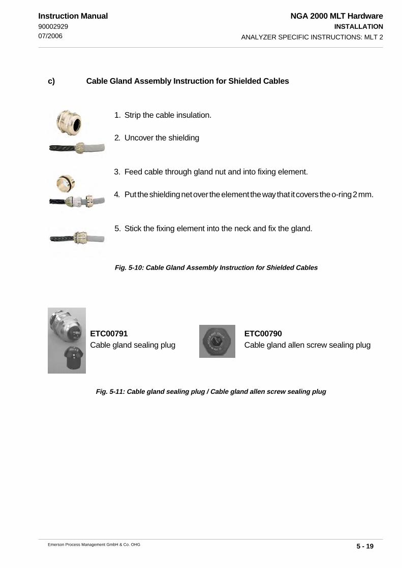
NGA 2000 MLT HardwareINSTALLATION
5 - 19Emerson Process Management GmbH & Co. OHG
Instruction Manual9000292907/2006
c) Cable Gland Assembly Instruction for Shielded Cables
1. Strip the cable insulation.
2. Uncover the shielding
3. Feed cable through gland nut and into fixing element.
4. Put the shielding net over the element the way that it covers the o-ring 2 mm.
5. Stick the fixing element into the neck and fix the gland.
ETC00791Cable gland sealing plug
ETC00790Cable gland allen screw sealing plug
Fig. 5-10: Cable Gland Assembly Instruction for Shielded Cables
Fig. 5-11: Cable gland sealing plug / Cable gland allen screw sealing plug
ANALYZER SPECIFIC INSTRUCTIONS: MLT 2
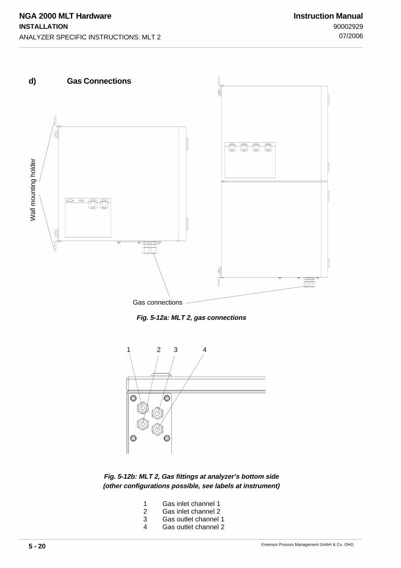
NGA 2000 MLT HardwareINSTALLATION
5 - 20 Emerson Process Management GmbH & Co. OHG
Instruction Manual90002929
07/2006
Fig. 5-12b: MLT 2, Gas fittings at analyzer’s bottom side(other configurations possible, see labels at instrument)
1 Gas inlet channel 12 Gas inlet channel 23 Gas outlet channel 14 Gas outlet channel 2
d) Gas Connections
Fig. 5-12a: MLT 2, gas connections
ANALYZER SPECIFIC INSTRUCTIONS: MLT 2
Gas connections
Wal
l mou
ntin
g ho
lder
1 2 43

NGA 2000 MLT HardwareINSTALLATION
5 - 21Emerson Process Management GmbH & Co. OHG
Instruction Manual9000292907/2006
5.4.3 MLT 3
All components of analyzers or analyzer modules are incorporated into a 1/1 19" housing.The housings are available as rack mounting (R) or as table-top (T) versions. For analyzer modulesthere is mounted a blind plate instead of an operation front panel.The equipment has an internal power supply with “autoranging” for operating voltages of 230 VAC or 120 V AC resp., 47-63 Hz.
The analyzers do not provide a power switch and are operable when con-nected to power.
Output signals and data are accessible at the rear panel via submin-d connectors. Depending onanalzyer variation not all signals are available. For information about pin-assignments see section21.
Fig. 5-13: MLT 3 (standard version), gas connections and voltage supply
IN = Gas inletOUT = Gas outlet (exhaust)CH 1 = Channel 1CH 2 = Channel 2
ANALYZER SPECIFIC INSTRUCTIONS: MLT 3
internal power supply(UPS 01 T)
Network
Input230 / 120 V ac
Gas connections
optional PCBs [SIO / DIO e. g.]
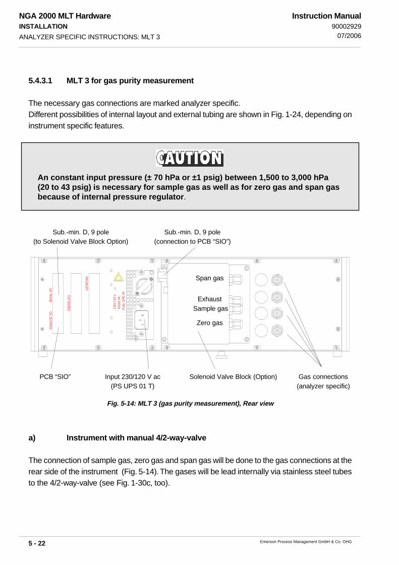
NGA 2000 MLT HardwareINSTALLATION
5 - 22 Emerson Process Management GmbH & Co. OHG
Instruction Manual90002929
07/2006
5.4.3.1 MLT 3 for gas purity measurement
The necessary gas connections are marked analyzer specific.Different possibilities of internal layout and external tubing are shown in Fig. 1-24, depending oninstrument specific features.
Fig. 5-14: MLT 3 (gas purity measurement), Rear view
An constant input pressure (± 70 hPa or ±1 psig) between 1,500 to 3,000 hPa(20 to 43 psig) is necessary for sample gas as well as for zero gas and span gasbecause of internal pressure regulator.
a) Instrument with manual 4/2-way-valve
The connection of sample gas, zero gas and span gas will be done to the gas connections at therear side of the instrument (Fig. 5-14). The gases will be lead internally via stainless steel tubesto the 4/2-way-valve (see Fig. 1-30c, too).
ANALYZER SPECIFIC INSTRUCTIONS: MLT 3
NET
WO
RK
DIG
ITAL
I/O
AN
ALO
G I/
O
SER
IAL
I/O
!
230
/120
V 5
0/60
Hz
ma
x. 2
40 V
A
PCB “SIO” Gas connections(analyzer specific)
Input 230/120 V ac(PS UPS 01 T)
Solenoid Valve Block (Option)
Sub.-min. D, 9 pole(connection to PCB “SIO”)
Sub.-min. D, 9 pole(to Solenoid Valve Block Option)
Span gas
Exhaust Sample gas
Zero gas

NGA 2000 MLT HardwareINSTALLATION
5 - 23Emerson Process Management GmbH & Co. OHG
Instruction Manual9000292907/2006
b) Instrument with solenoid valve block
The connection of sample gas, zero gas and span gas will be done to the solenoid valve block atthe rear side of the instrument (Fig. 5-14 and 5-15). The common exhaust of solenoid valve blockis be lead to the real sample gas inlet of the instrument via stainless steel tube (see Fig. 1-30a).
Fig. 5-15: Solenoid valve block MLT 3 (gas purity measurement) (side view)
c) Instrument with quick shutoff connector
The connection of sample gas will be done to the quick shutoff connector at the front side of theinstrument (Fig. 5-16). The sample gas will be lead internally via stainless steel tube either to the4/2-way-valve or to a gas outlet at the rear side of instrument and then to the sample gas inlet ofthe solenoid valve block (see Fig. 1-30b, too).All other gas connections will be done as described in section 5.3 and 1.8.
Fig. 5-16: MLT 3 (gas purity measurement), front view
Flow meter Operation front panelQuick shutoff connector(sample ges input, option)
Manual 4/2-way-valve(option)
Rosemount Analytical NGA 2000
F3 F4 F5F2F1
ANALYZER SPECIFIC INSTRUCTIONS: MLT 3
span gas
exhaust(common)
sample gas
zero gas

NGA 2000 MLT HardwareINSTALLATION
5 - 24 Emerson Process Management GmbH & Co. OHG
Instruction Manual90002929
07/2006
Fig. 5-17: MLT 4, Voltage supply
5.4.4 MLT 4
All components of analyzers or analyzer modules are incorporated into a 1/1 19" housing.The housings are available as rack mounting (R) or as table-top (T) versions. For analyzer modulesthere is mounted a blind plate instead of an operation front panel.These analyzers need DC 24 V power supply utilizing an external power supply unit. They providea three pole power input connector located at the rear panel.
It is recommended to use original Emerson Process Management powersupply units and supply cords. If a supplement is used take care of correctpin assignment, as given on the analyzer´s rear panel!
The analyzers do not provide a power switch and are operable when con-nected to power.
For analyzer module (A) [external installation or platform mounting] it isnot allowed to supply the module from front and rear simultaneously !For external installation connections on frontside absolutely have to closedwith the blind plate delivered from our factory to be in agreement with theCE conformity.!
Output signals and data are accessible at the rear panel via submin-d connectors. Depending onanalzyer variation not all signals are available. For information about pin-assignments see section21.
ANALYZER SPECIFIC INSTRUCTIONS: MLT 4
Plug 24 V dc
Network
optional PCBs[SIO / DIO e. g.]

NGA 2000 MLT HardwareINSTALLATION
5 - 25Emerson Process Management GmbH & Co. OHG
Instruction Manual9000292907/2006
Fig. 5-18: MLT 4, gas connections
in = Gas inletout = Gas outlet
1 = measuring channel 12 = measuring channel 23 = measuring channel 3
Purge = purge gas (housing)
Note!Purge option combination is only available with one or two channel analyzer.
ANALYZER SPECIFIC INSTRUCTIONS: MLT 4

NGA 2000 MLT HardwareINSTALLATION
5 - 26 Emerson Process Management GmbH & Co. OHG
Instruction Manual90002929
07/2006
5.4.5 CAT 200
CAT 100 analyzers are designed for wall mounting and intended to be outdoor installedtaking into account the ambient temperature limits as given in the technical data section ofthis manual..
This current instruction manual covers using the CAT 200 analyzer forgeneral purpose applications only!
Installation, startup and maintenance for operation in hazardous areas aredescribed in detail in a separate instruction manual, shipped together witheach such analyzer and are not subject of the current instruction manual!
ANALYZER SPECIFIC INSTRUCTIONS: CAT 200
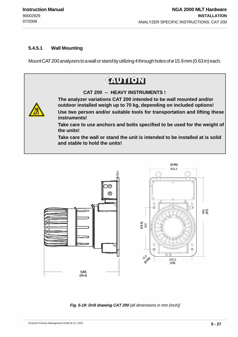
NGA 2000 MLT HardwareINSTALLATION
5 - 27Emerson Process Management GmbH & Co. OHG
Instruction Manual9000292907/2006
CAT 200 -- HEAVY INSTRUMENTS !The analyzer variations CAT 200 intended to be wall mounted and/oroutdoor installed weigh up to 70 kg, depending on included options!Use two person and/or suitable tools for transportation and lifting theseinstruments!Take care to use anchors and bolts specified to be used for the weight ofthe units!Take care the wall or stand the unit is intended to be installed at is solidand stable to hold the units!
Fig. 5-19: Drill drawing CAT 200 [all dimensions in mm (Inch)]
5.4.5.1 Wall Mounting
Mount CAT 200 analyzers to a wall or stand by utilizing 4 through holes of ø 15.9 mm (0.63 in) each.
ANALYZER SPECIFIC INSTRUCTIONS: CAT 200
(0.85)
(13)
(25.4)
(0.63
)
(14.
3)
(27)

NGA 2000 MLT HardwareINSTALLATION
5 - 28 Emerson Process Management GmbH & Co. OHG
Instruction Manual90002929
07/2006
ELECTRICAL SHOCK HAZARD!Installation and connecting mains and signal cables are subject to qualifiedpersonnel only taking into account all applicable standards and legislativerequirements!Failure to follow may cause warranty invalidation, property damage and/orpersonal injury or death! Mains and signal cables need to be connected tointernal srew terminals requiring to work at open housing near life parts!Installation of this instrument is subject to qualified personnel only, familiarwith the resulting potential risks!CAT 200 gas analyzers do not provide a mains switch! A mains switch orcircuit breaker has to be provided in the building installation. This switchhas to be installed near by analyzer, must be easily operator accessible andhas to be assigned as disconnector for the analyzer.The junction box must be protected by fuse supply (10 A fuse) which has abreaking capacity adjusted to the short circuit of the equipment.The analyzer provides a protective earth terminal. To prevent electrical shockhazards the instrument must be connected to a protective earth. Thereforethe instrument has to be connected to mains by using a three wire mainscable with earth conductor!Any interruption of the earth connector inside or outside the instrument ordisconnecting the earth terminal may cause potential electrical shockhazzard!The analyzer does not provide a mains switch and is operable whenconnected to power.
5.4.5.2 Electrical Connections
To ensure protection against water and dust use cable glands with minimumIP 65 classification!The junction box provides at its left side one threat M20x1.5 and at its rightside up to three threats M16x1.5 for installing cable glands.The left gland is the mains power cord entry, the right side glands for signalcables.Not used threats must be sealed by approved sealing plugs (factory deliverycondition).
ANALYZER SPECIFIC INSTRUCTIONS: CAT 200

NGA 2000 MLT HardwareINSTALLATION
5 - 29Emerson Process Management GmbH & Co. OHG
Instruction Manual9000292907/2006
This analyzer model is supplied by an internatl wide range power supply, automaticallyadapting to the voltage at site.
All cables (mains power cord and signal cables) are connected via screw terminals locatedinside an junction box right above the analyzer dome.
See the label on the junction box cover for detailed terminal assignments.
Cables entering the junction box should be kept as short as possible when inside the box.
Mains terminals are capable to connect cables up to 4 mm2 cross section.
ANALYZER SPECIFIC INSTRUCTIONS: CAT 200
EXPLOSION HAZARD!Instruments covered by an approval for hazardous areas (identifiable by aterm „ATEX" on the nameplate label) MUST be equipped with cable glands,marked EEx e and ATEX!This applies, too, when the instrument currently is NOT installed in ahazardous area!
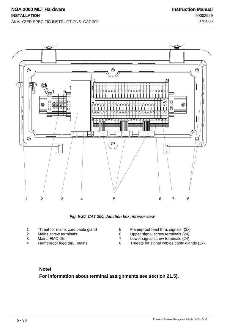
NGA 2000 MLT HardwareINSTALLATION
5 - 30 Emerson Process Management GmbH & Co. OHG
Instruction Manual90002929
07/2006ANALYZER SPECIFIC INSTRUCTIONS: CAT 200
Note!For information about terminal assignments see section 21.5).
Fig. 5-20: CAT 200, Junction box, interior view
1 Threat for mains cord cable gland2 Mains screw terminals3 Mains EMC filter4 Flameproof feed thru, mains
5 Flameproof feed thru, signals (3x)6 Upper signal screw terminals (24)7 Lower signal screw terminals (24)8 Threats for signal cables cable glands (3x)
1 2 3 4 5 6 7 8
1 24
241
1 5

NGA 2000 MLT HardwareINSTALLATION
5 - 31Emerson Process Management GmbH & Co. OHG
Instruction Manual9000292907/2006
Note!Reference option is only available with single or two channel analyzer.
ANALYZER SPECIFIC INSTRUCTIONS: CAT 200
Fig. 5-21: CAT 200, Analyzer’s bottom view at gas fittings
5.4.5.3 Gas Connections
8 9 10 11
1 2 3 4
5 6 7
Table 5-1: CAT 200, Assignment of gas fittings
Analyzer Configuration
Serial Tubing 1 - Gas in 2 - Gas out
1 - Gas in (ch 1) 2 - Gas out (ch 1) 3 - Gas in (ch 2) 4 - Gas out (ch 2)
5 - Gas in (ch 3) 6 - Gas out (ch 3) 7 - Gas in (ch 4) 8 - Gas out (ch 4)
2 - Gas out
(Sample, zero &
span gas)*
5 - Span gas 1 in 6 - Span gas 2 in 8 - Zero gas in
7 - Sample gas in
1 - Gas in (ch 1) 2 - Gas out (ch 1) 3 - Gas in (ch 2) 4 - Gas out (ch 2)
5 - Span gas 1 in 6 - Span gas 2 in 8 - Zero gas 1 in 10 - Zero gas 2 in
1 - Gas in (ch 1) 2 - Gas out (ch 1) 3 - Gas in (ch 2) 4 - Gas out (ch 2)
5 - Gas in (ref 1) 6 - Gas out (ref 1)7 - Gas in (ref 2)
1 or
10 - Gas in (ref 2)2
8 - Gas out (ref 2)1 or
11 - Gas out (ref 2)2
CAT housing purge (option) 7 - Purge gas in 8 - Purge gas out
1 without housing purge
Gas Fitting Assignment
Parallel tubing with differential
measurement (option)
Parallel tubing with 2
solenoid valve blocks (option)
2 with housing purge
* Standard Gas out = gas exhaust, valve block output internally connected to MLT gas input.
Option: Valve block output may be used for external sample handling system (special configuration).
Parallel tubing
Serial tubing with 1
solenoid valve block (option)

NGA 2000 MLT HardwareINSTALLATION
5 - 32 Emerson Process Management GmbH & Co. OHG
Instruction Manual90002929
07/2006
5.5 Wiring Signal Terminals
Emerson Process Managament has taken any effort during the MLT series development processto ensure electromagnetically compatibility (EMC; concerning emission and immunity), stated byEMC measurements according EN 61326.Nevertheless EMC is not only influenced by the instrument‘s design, but widely by the installationprocedure at site, too. Take care of the following sections and measures described within to ensuresafe and trouble-free analyzer operation!
5.5.1 Electrical Connections in General
To minimize electromagnetically interferences by the analyzer‘s environment it is necessary tocarefully execute all electrical connections between the analyzer and other instruments:
It is recommended to use shielded cables for signal lines, only!Shield has to be connected to the housing at both ends of one connection (fig. 5-22).
Fig. 5-22:Shielded Signal Cable,shield connected at both ends
Local on-site conditions usually differ from test conditions and may require special measures. Thisis when strong fields are expected, potentially generating high parasitic currents on the cable shield. Such currents result in differences of potential between connected housings.Two possible measures to avoid parasitic currents are described, whereat installation personnelfamiliar with EMC problems has to decide about the use of either measure:
Shield is connected at one side of the cable only (recommended to the analyzer‘s housing):Protection against external distrubances is increased but influence by parasitic currents isprevented due to opening the ground loop.
Fig. 5-23: Shielded Signal Cable,shield connected at one end
WIRING SIGNAL TERMINALS: ELECTRICAL CONNECTIONS IN GENERAL

NGA 2000 MLT HardwareINSTALLATION
5 - 33Emerson Process Management GmbH & Co. OHG
Instruction Manual9000292907/2006 WIRING SIGNAL TERMINALS: ELECTRICAL CONNECTIONS IN GENERAL
Using double-shielded cables:In this case one shield is connected to the analyzer‘s housing while the other shield isconnected to the external equipment.This gives an advantage when both instruments are supplied by different supply networks(e.g. when installed in different buildings).This measure is more costlybut offers best immunity against distrubances from outer fieldsand from parasitic currents.
Fig. 5-24:Double-shielded Signal Cable,shields connected at both sides

NGA 2000 MLT HardwareINSTALLATION
5 - 34 Emerson Process Management GmbH & Co. OHG
Instruction Manual90002929
07/2006WIRING SIGNAL TERMINALS: WIRING INDUCTIVE LOADS
5.5.2 Wiring Inductive Loads
Switching inductive loads is a standard application generating electromagnetic disturbances:The moment an inductive load (e.g. relay, valve, etc.) is switched off, it‘s magnetic field defies thechange of current flow, generating high voltages (up to hundrets of volts) at the coil‘s contacts. Thisimpulse reproduces on connected wires and may influence electrical equipment nearby or destroysignal inputs and/or outputs on electronic boards.A simple measure helps to avoid such effects:
Shunt a silicon diode to the inductive load‘s contacts shorting the voltage impulse just at it‘ssource.The diode‘s cathode needs to be connected to the positive side of the coil, the anode to thenegative side (fig. 5-25).
Suitable filter components are available on request for standard valves.
Fig. 5-25: Suppressor Diode for Inductive Loads
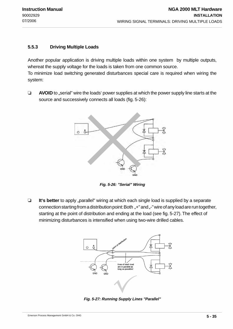
NGA 2000 MLT HardwareINSTALLATION
5 - 35Emerson Process Management GmbH & Co. OHG
Instruction Manual9000292907/2006
5.5.3 Driving Multiple Loads
Another popular application is driving multiple loads within one system by multiple outputs,whereat the supply voltage for the loads is taken from one common source.To minimize load switching generated disturbances special care is required when wiring thesystem:
AVOID to „serial" wire the loads‘ power supplies at which the power supply line starts at thesource and successively connects all loads (fig. 5-26):
It‘s better to apply „parallel" wiring at which each single load is supplied by a separateconnection starting from a distribution point: Both „+" and „-" wire of any load are run together,starting at the point of distribution and ending at the load (see fig. 5-27). The effect ofminimizing disturbances is intensified when using two-wire drilled cables.
WIRING SIGNAL TERMINALS: DRIVING MULTIPLE LOADS
Fig. 5-26: ”Serial” Wiring
Fig. 5-27: Running Supply Lines "Parallel”

NGA 2000 MLT HardwareINSTALLATION
5 - 36 Emerson Process Management GmbH & Co. OHG
Instruction Manual90002929
07/2006
5.5.4 Driving High Current Loads
Loads with currents exceeding the rated currents specified for MLT analyzers outputs must not bedriven directly by digital or relay outputs.Driving such loads requires external relays acting as decoupling devices: The MLT output drivesthe external relay, which itself drives the load.It is recommended to use separate supplies for analyzer and high current loads to minimizeinterferences (fig. 5-28).As described before using suppressor diodes for inductive loads is strongly recommended!
WIRING SIGNAL TERMINALS: DRIVING HIGH CURRENT LOADS
Fig. 5-28: Driving High Current Loads
Load
External relay

NGA 2000 MLT HardwareSWITCHING ON
6 - 1Emerson Process Management GmbH & Co. OHG
Instruction Manual90002929
07/2006
6. Switching On
Take care of the safety instructions as given at the beginning of this manualwhile working at and inside the instruments!
Once the instrument has been correctly assembled and installed in accordance with the general
instructions given in section 5., the equipment is ready for operation.
The equipment is switched on by providing the required voltage.
Note (for MLT analyzers only)!The analyzer must be switched on only after switching on all modulesconnected to the network. Be sure to observe the network termination(section 1.10) !
Upon switching on, the analyzer will perform a self-diagnostic test routine, followed by the binding
of all connected analyzer modules.
For additional informations about display messages during start-up see respective software
manual.
Note!Analyzer needs 15 to 50 minutes to warm-up after switch on, depending onthe installed detectors and themostatting temperature !For MLT 3 for gas purity measurment with suppressed ranges of 98 - 100 %CO2 we recommend to warm-up the analyzer over night and start calibrationnext morning to achieve best results!
Note (for analyzers with TEO2 sensors only)!When installing a new sensor or starting the instrument for the first time, itmay take as long as eight hours for the analyzer to purge down to thelowest operating range.

NGA 2000 MLT HardwareSWITCHING ON
6 - 2 Emerson Process Management GmbH & Co. OHG
Instruction Manual90002929
07/2006
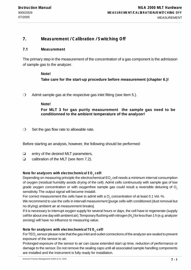
7 - 1
NGA 2000 MLT HardwareMEASUREMENT/CALIBRATION//SWITCHING OFF
Emerson Process Management GmbH & Co. OHG
Instruction Manual9000292907/2005
7. Measurement / Calibration / Switching Off
7.1 Measurement
The primary step in the measurement of the concentration of a gas component is the admissionof sample gas to the analyzer.
Note!Take care for the start-up procedure before measurement (chapter 6.)!
Admit sample gas at the respective gas inlet fitting (see Item 5.).
Note!For MLT 3 for gas purity measurement the sample gas need to beconditionned to the ambient temperature of the analyzer!
Set the gas flow rate to allowable rate.
Before starting an analysis, however, the following should be performed:
entry of the desired MLT parameters, calibration of the MLT (see Item 7.2).
Note for analyzers with electrochemical EO2 cell!Depending on measuring principle the electrochemical EO2 cell needs a minimum internal consumptionof oxygen (residual humidity avoids drying of the cell). Admit cells continuously with sample gas of lowgrade oxygen concentration or with oxygenfree sample gas could result a reversible detuning of O
2
sensitivity. The output signal will become instabil.For correct measurement the cells have to admit with a O2 concentration of at least 0.1 Vol.-%.We recommend to use the cells in intervall measurement [purge cells with conditioned (dust removal butno drying) ambient air at measurement breaks].If it is necessary to interrupt oxygen supply for several hours or days, the cell have to regenerate (supplycell for about one day with ambient air). Temporary flushing with nitrogen (N
2) for less than 1 h (e.g. analyzer
zeroing) will have no influence to measuring value.
Note for analyzers with electrochemical TEO2 cell!For TEO2 sensor please note that the gas inlet and outlet connections of the analyzer are sealed to preventexposure of the sensor to air.Prolonged exposure of the sensor to air can cause extended start up time, reduction of performance ordamage to the sensor. Do not remove the sealing caps until all associated sample handling componentsare installed and the instrument is fully ready for installation.
MEASUREMENT

7 - 2
NGA 2000 MLT HardwareMEASUREMENT/CALIBRATION//SWITCHING OFF
Emerson Process Management GmbH & Co. OHG
Instruction Manual90002929
07/2005CALIBRATION
7.2 Calibration
To insure correct measurement results, zeroing and spanning should be carried out once a week.Other intervals are possible.The zero-level must always first be set before any other calibrations are attempted.
For the calibration procedure the required test gases have to be fed to the analyzer through therespective gas inlets (cf. section 5.3) with a no - back - pressure gas flow rate of about 1 l/min (thesame as with sample gas) !
For correct adjustment and/or “system calibration” of the analyzer please look at MLTsoftware manual !
General notes!Each measuring channel of MLT can be equipped with up to four various measurement ranges.There is the possibility to adjust the sensitivity (span) of the measurement ranges together (standard) orseparately.The zero-gas adjustment is carried out together for all measurement ranges of a measuring channel. Off-set setting (value differing from zero i. e.) can be provided if a corresponding zero gas requires this (e.g.substitute gas instead of zero gas with nitrogen).The span adjustment can be carried out at common sizing of all measurement ranges in the largestmeasurement range. Due to a common linearization (small measurement ranges represent merely arange of the complete) for all measurement ranges as standard (divergent procedures look at orderconfirmation) the specifications for the linearity deviation are valid for all measurement ranges, i. e. for thesmallest full-scale range. The calibration deviation to be expected depends on the quality of the test gasand affects all measurement ranges in a similar manner.Certain applications and legal handicaps can require adjustment of separate measurement ranges,
though!
An constant input pressure (± 70 hPa or ±1 psig) between 1,500 to 3,000 hPa(20 to 43 psig) is necessary for sample gas as well as for zero gas and span gasbecause of internal pressure regulator (different input pressures look at orderconfirmation).
MLT 1 ULCO and MLT 3 for gas purity measurement have to be calibrated on adaily basis! Other far longer intervals are application dependent (see TÜVsuitability test report with prolonged calibrating interval)!

7 - 3
NGA 2000 MLT HardwareMEASUREMENT/CALIBRATION//SWITCHING OFF
Emerson Process Management GmbH & Co. OHG
Instruction Manual9000292907/2005 CALIBRATION
7.2.1 Test Gases
7.2.1.1 Zero Gas
For zeroing, the analyzer has to be purged with nitrogen (N2) or adequate zero gas [e. g. synth. air
or conditionned air (but not for O2 - measurement)]
.7.2.1.2 Span Gas
The calibration of all another analyzers should be done with pure span gases in order to preventinterferences between the gases (e. g., CO
2 and CO) measured by the analyzer, using test gas
mixtures.The concentration range of the span gas has to be in a range of 80 - 100 % (70 - 110 %) of thefull - scale range of the respective measuring channel. For lower span gas concentrations themeasuring accuracy could be lower for sample gas concentrations, which are higher than the spangas concentration! For test gas concentration see certification of the test gas bottles.Spanning for oxygen measurement can be done using conditionned ambient air as span gas, ifthe oxygen concentration is known and constant.
To calibrate the MLT 1 ULCO internal H2O channel (0-3 Vol.-%, used for cross compensation), use
water vapor saturated N2 according to saturation characteristic (Item 22.) as span gas. Purge N
2
through a gas-blubber bottle, filled with distilled water and in a little bit higher ambient temperatureas necessary Connect a second vessel into a kyrostat (to hold ambient temperature constant) inseries to get defined dew point.
Take care of the safety instructions applicable for the gases (samplegases and test gases) and for the gas bottles containing these gases!
Max. permissible gas pressure: 1,500 hPa, except instruments for gas puritymeasurement (see chapter 5.4.3.1), with integrated valve blocks (see page 5-8) and/orparamagnetic Oxygen sensor (see table page 20-4)!An constant input pressure (± 70 hPa or ±1 psig) between 1,500 to 3,000 hPa (20 to 43psig) is necessary for sample gas as well as for zero gas and span gas because ofinternal pressure regulator (different input pressures look at order confirmation).All calibration gases need to be kept to the same temperature as sample gas!The calibration of MLT 1 ULCO must be done using pure test gases.
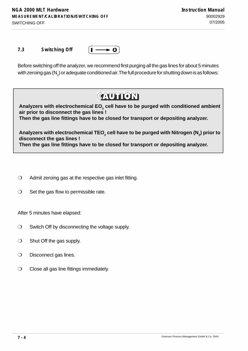
7 - 4
NGA 2000 MLT HardwareMEASUREMENT/CALIBRATION//SWITCHING OFF
Emerson Process Management GmbH & Co. OHG
Instruction Manual90002929
07/2005
7.3 Switching Off
Before switching off the analyzer, we recommend first purging all the gas lines for about 5 minuteswith zeroing gas (N
2) or adequate conditioned air. The full procedure for shutting down is as follows:
Admit zeroing gas at the respective gas inlet fitting.
Set the gas flow to permissible rate.
After 5 minutes have elapsed:
Switch Off by disconnecting the voltage supply.
Shut Off the gas supply.
Disconnect gas lines.
Close all gas line fittings immediately.
SWITCHING OFF
Analyzers with electrochemical EO2 cell have to be purged with conditioned ambientair prior to disconnect the gas lines !Then the gas line fittings have to be closed for transport or depositing analyzer.
Analyzers with electrochemical TEO2 cell have to be purged with Nitrogen (N2) prior todisconnect the gas lines !Then the gas line fittings have to be closed for transport or depositing analyzer.

NGA 2000 MLT HardwareTROUBLESHOOTING
10 - 1Emerson Process Management GmbH & Co. OHG
Instruction Manual90002929
07/2006
10. Troubleshooting
Take care of the safety instructions as given at the beginning of this manualwhile working at and inside the instruments!
Working inside the instruments is subject to briefed personnel familiar withpotential risks!
10.1 Instrument has no function (LCD display is dark)
Possible Causes Check / Correct
a) External supply voltage is absent: Check connection mains line → MLT / PS
MLT 1/4: Check external power supply
- DC polarity is reversed Check electrical supply
b) Possible internal failures: Check internal voltage supply (Section 11.1.1)
MLT 1/4: Check fuses of PCB “LEM” (Section 12.4)
MLT 2: Check internal fuses F1 and F2 (Section 12.4)
c) Internal connections incorrect or absent: Check internal connections:
Check whether PCB “ACU” is in correct place
(Fig. 1-31)
Check PCB's “ACU-AFP” (front panel)
connection cable
d) PCB “AFP” board or LC display defective Exchange front panel (see 12.2)
e) PCB “ACU” defective: Replace ACU (see 12.3)
NO FUNCTION (LCD DISPLAY)
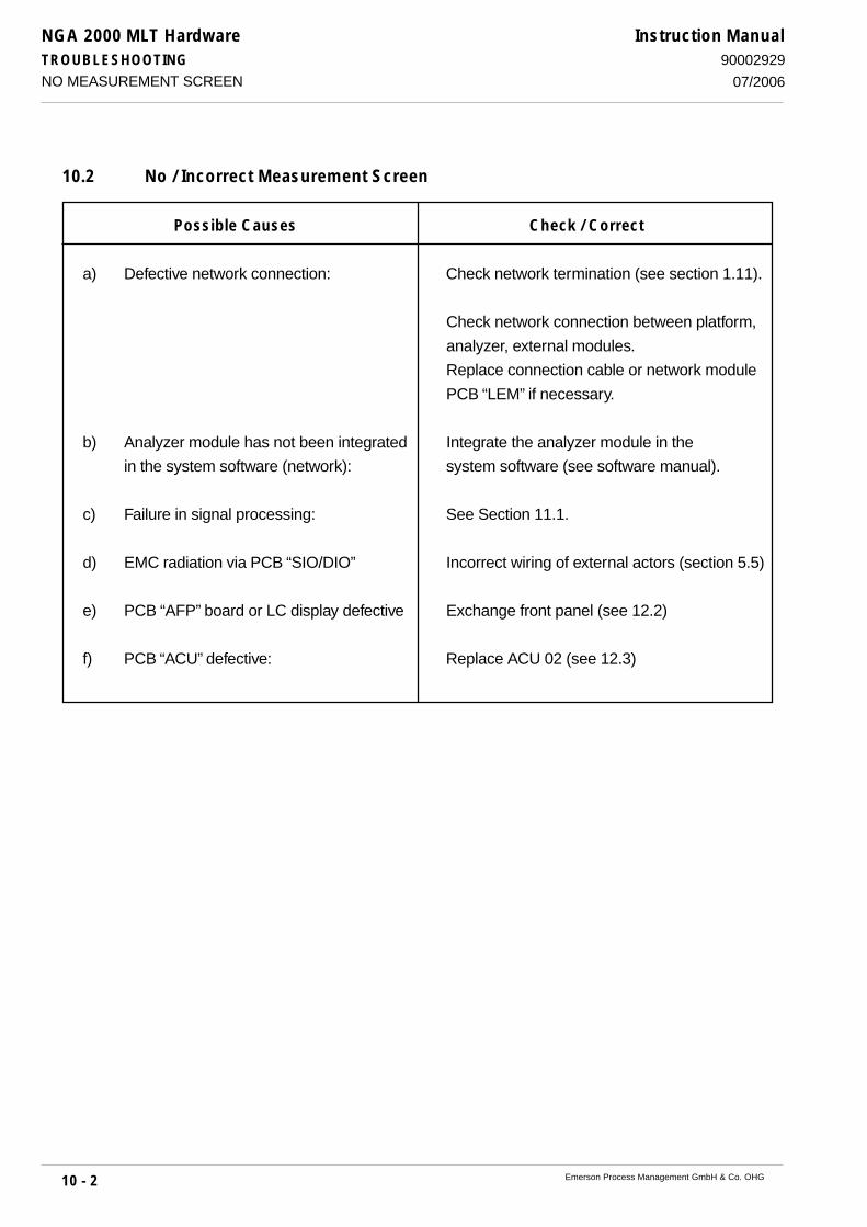
NGA 2000 MLT HardwareTROUBLESHOOTING
10 - 2 Emerson Process Management GmbH & Co. OHG
Instruction Manual90002929
07/2006
10.2 No / Incorrect Measurement Screen
Possible Causes Check / Correct
a) Defective network connection: Check network termination (see section 1.11).
Check network connection between platform,
analyzer, external modules.
Replace connection cable or network module
PCB “LEM” if necessary.
b) Analyzer module has not been integrated Integrate the analyzer module in the
in the system software (network): system software (see software manual).
c) Failure in signal processing: See Section 11.1.
d) EMC radiation via PCB “SIO/DIO” Incorrect wiring of external actors (section 5.5)
e) PCB “AFP” board or LC display defective Exchange front panel (see 12.2)
f) PCB “ACU” defective: Replace ACU 02 (see 12.3)
NO MEASUREMENT SCREEN

NGA 2000 MLT HardwareTROUBLESHOOTING
10 - 3Emerson Process Management GmbH & Co. OHG
Instruction Manual90002929
07/2006
10.3 Display Messages
Several operating conditions of the analyzer / module are controlled and signalized via correspond-
ing messages of the display.
Failures can be shown at the menu “Status” → “Status details” → “Failures” (Item “4.1.1 Status
details” of software manual).
10.3.1 Chopper Fail
Possible Causes Check / Correct
a) Chopper fail: Check connection to PCB “PIC” Fig. 1-32) or
PCB “DSP” Fig. 1-33) resp.;
see section 11.1.3
10.3.2 Raw Signal Too High / Low
Possible Causes Check / Correct
a) Concentration of sample gas is to high. Reduce gas concentration.
Use another analyzer suitable for the
concentration range involved.
b) Incorrect physical zero point Check and adjust physical zero point alignment
(see Section 17.5 / 11.1.6)
.
c) Contamination of the gas paths Check if photometric components are dirty,
clean or replace the components if necessary
(cf. Section 17.).
Check and adjust physical zero point alignment
(see Section 17.5 / 11.1.6)
DISPLAY MESSAGES
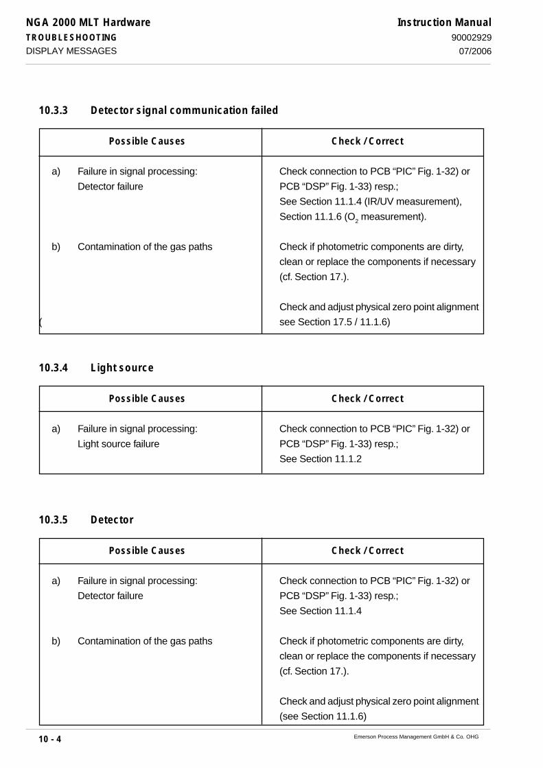
NGA 2000 MLT HardwareTROUBLESHOOTING
10 - 4 Emerson Process Management GmbH & Co. OHG
Instruction Manual90002929
07/2006
10.3.3 Detector signal communication failed
Possible Causes Check / Correct
a) Failure in signal processing: Check connection to PCB “PIC” Fig. 1-32) or
Detector failure PCB “DSP” Fig. 1-33) resp.;
See Section 11.1.4 (IR/UV measurement),
Section 11.1.6 (O2 measurement).
b) Contamination of the gas paths Check if photometric components are dirty,
clean or replace the components if necessary
(cf. Section 17.).
Check and adjust physical zero point alignment
( see Section 17.5 / 11.1.6)
10.3.4 Light source
Possible Causes Check / Correct
a) Failure in signal processing: Check connection to PCB “PIC” Fig. 1-32) or
Light source failure PCB “DSP” Fig. 1-33) resp.;
See Section 11.1.2
10.3.5 Detector
Possible Causes Check / Correct
a) Failure in signal processing: Check connection to PCB “PIC” Fig. 1-32) or
Detector failure PCB “DSP” Fig. 1-33) resp.;
See Section 11.1.4
b) Contamination of the gas paths Check if photometric components are dirty,
clean or replace the components if necessary
(cf. Section 17.).
Check and adjust physical zero point alignment
(see Section 11.1.6)
DISPLAY MESSAGES
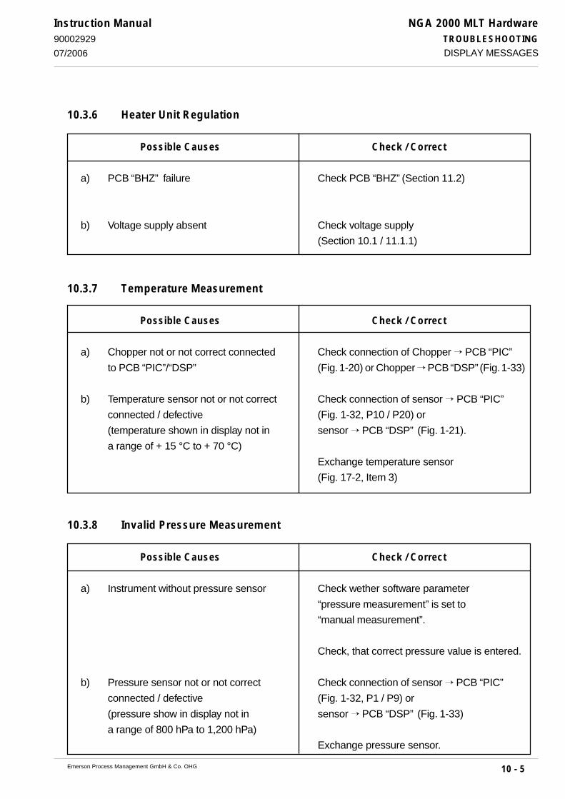
NGA 2000 MLT HardwareTROUBLESHOOTING
10 - 5Emerson Process Management GmbH & Co. OHG
Instruction Manual90002929
07/2006
10.3.6 Heater Unit Regulation
Possible Causes Check / Correct
a) PCB “BHZ” failure Check PCB “BHZ” (Section 11.2)
b) Voltage supply absent Check voltage supply
(Section 10.1 / 11.1.1)
10.3.7 Temperature Measurement
Possible Causes Check / Correct
a) Chopper not or not correct connected Check connection of Chopper → PCB “PIC”
to PCB “PIC”/“DSP” (Fig. 1-20) or Chopper → PCB “DSP” (Fig. 1-33)
b) Temperature sensor not or not correct Check connection of sensor → PCB “PIC”
connected / defective (Fig. 1-32, P10 / P20) or
(temperature shown in display not in sensor → PCB “DSP” (Fig. 1-21).
a range of + 15 °C to + 70 °C)
Exchange temperature sensor
(Fig. 17-2, Item 3)
10.3.8 Invalid Pressure Measurement
Possible Causes Check / Correct
a) Instrument without pressure sensor Check wether software parameter
“pressure measurement” is set to
“manual measurement”.
Check, that correct pressure value is entered.
b) Pressure sensor not or not correct Check connection of sensor → PCB “PIC”
connected / defective (Fig. 1-32, P1 / P9) or
(pressure show in display not in sensor → PCB “DSP” (Fig. 1-33)
a range of 800 hPa to 1,200 hPa)
Exchange pressure sensor.
DISPLAY MESSAGES

NGA 2000 MLT HardwareTROUBLESHOOTING
10 - 6 Emerson Process Management GmbH & Co. OHG
Instruction Manual90002929
07/2006
10.3.9 External Input
Possible Causes Check / Correct
a) Configuration of PCB “DIO” incorrect Check correct software configuration of “DIO”
b) EMC radiation via PCB “DIO” Incorrect wiring of external actors (section 5.5)
c) PCB “DIO” not or not correct connected / Check correct connection of PCB “DIO”.
defective
Exchange PCB “DIO”.
d) PCB “ACU” defective: Replace ACU 02 (see 12.3)
10.4 No or incorrect Analog Outputs / Digital I/O's
Possible Causes Check / Correct
a) Configuration of PCB “SIO/DIO” incorrect Check correct software configuration of PCB's
“SIO/DIO”
b) EMV radiation via PCB “SIO/DIO” Incorrect wiring of external actors (section 5.5)
c) PCB “SIO/DIO” not or not correct Check correct connection of PCB “SIO/DIO”.
connected / defective
Exchange PCB “SIO/DIO”.
d) Additional PCB “SIA” Check correct connection of PCB “SIA” → “SIO”.
(more than two analog outputs) (Fig.1-35)
not or not correct connected / defective Exchange PCB “SIA/SIO”.
e) PCB “ACU” defective: Replace ACU 02 (see 12.3)
DISPLAY MESSAGES - NO OR INCORRECT ANALOG OUTPUTS / DIGITAL I/O'S
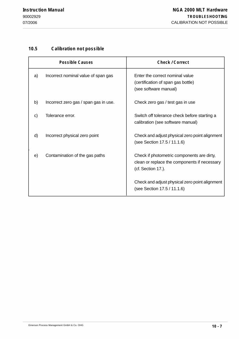
NGA 2000 MLT HardwareTROUBLESHOOTING
10 - 7Emerson Process Management GmbH & Co. OHG
Instruction Manual90002929
07/2006 CALIBRATION NOT POSSIBLE
10.5 Calibration not possible
Possible Causes Check / Correct
a) Incorrect nominal value of span gas Enter the correct nominal value
(certification of span gas bottle)
(see software manual)
b) Incorrect zero gas / span gas in use. Check zero gas / test gas in use
c) Tolerance error. Switch off tolerance check before starting a
calibration (see software manual)
d) Incorrect physical zero point Check and adjust physical zero point alignment
(see Section 17.5 / 11.1.6)
.
e) Contamination of the gas paths Check if photometric components are dirty,
clean or replace the components if necessary
(cf. Section 17.).
Check and adjust physical zero point alignment
(see Section 17.5 / 11.1.6)

NGA 2000 MLT HardwareTROUBLESHOOTING
10 - 8 Emerson Process Management GmbH & Co. OHG
Instruction Manual90002929
07/2006
10.6 Fluctuating or erroneous display
Possible Causes Check / Correct
a) Leakage into gas circuit. Perform a leakage check (see Section 14).
b) Ambient air contains gas constituent to Purge the instrument.
be measured in excessive concentration.
c) Gas pressure subject to Check the gas lines preceding and following
excessive fluctuations. the instrument.
Eliminate any restrictions found beyond the
gas outlet fitting.
Reduce pumping rate or flow rate.
d) Contamination of the gas paths Check if photometric components are dirty,
clean or replace the components if necessary
(cf. Section 17.).
Check and adjust physical zero poin alignmentt
(see Section 17.5 / 11.1.6)
e) Barometric pressure effects See Section 10.3.8
f) Temperature below the dew point Check the temperature of the gas paths
in the gas paths and eliminate any reason of condensation.
Maintain all temperatures at values at least
10 °C above the dew point of sample gas.
Check gas paths and gas conditionning
for condensation and clean or exchange.
FLUCTUATING OR ERRONEOUS DISPLAY

NGA 2000 MLT HardwareTROUBLESHOOTING
10 - 9Emerson Process Management GmbH & Co. OHG
Instruction Manual90002929
07/2006
10.7 Response time too long (t90 time)
Possible Causes Check / Correct
a) Incorrect response time (t90
time). Check the value for t90
time
(see software manual)
b) Pumping rate inadequate. Check diaphragms and membranes of
gas sampling pump.
The feeder line between the sampling point
and the instrument is too long.
Use a larger, external pump;
consider adding a bypass line to the
process stream for sampling purposes
(see Section 5.3).
c) Contamination of the gas paths Check if photometric components are dirty,
clean or replace the components if necessary
(cf. Section 17.).
Check and adjust physical zero point alignment
(see Section 17.5 / 11.1.6)
RESPONSE TIME TOO LONG (T90
TIME)

NGA 2000 MLT HardwareTROUBLESHOOTING
10 - 10 Emerson Process Management GmbH & Co. OHG
Instruction Manual90002929
07/2006
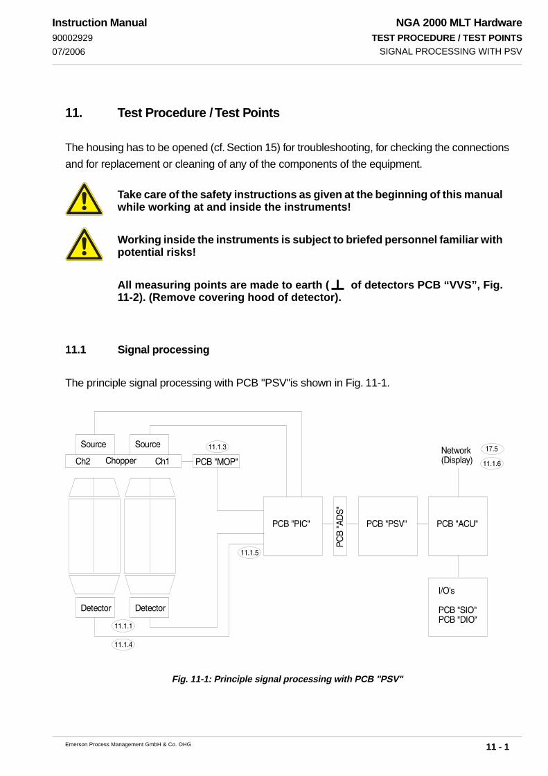
NGA 2000 MLT HardwareTEST PROCEDURE / TEST POINTS
11 - 1Emerson Process Management GmbH & Co. OHG
Instruction Manual90002929
07/2006
!"#
$$
$$%
$$&
'$(
$$(
$$)
11. Test Procedure / Test Points
The housing has to be opened (cf. Section 15) for troubleshooting, for checking the connections
and for replacement or cleaning of any of the components of the equipment.
Take care of the safety instructions as given at the beginning of this manualwhile working at and inside the instruments!
Working inside the instruments is subject to briefed personnel familiar withpotential risks!
All measuring points are made to earth ( of detectors PCB “VVS”, Fig.11-2). (Remove covering hood of detector).
11.1 Signal processing
The principle signal processing with PCB "PSV"is shown in Fig. 11-1.
Fig. 11-1: Principle signal processing with PCB "PSV"
SIGNAL PROCESSING WITH PSV

NGA 2000 MLT HardwareTEST PROCEDURE / TEST POINTS
11 - 2 Emerson Process Management GmbH & Co. OHG
Instruction Manual90002929
07/2006
“+” “-” “A” “ ”
R11
(IR)
R5 (UV)
R1 (UV)
Fig. 11-2: PCB "VVS"
11.1.1 Internal Voltage Supply
Test point: “+” or “-” of detector PCB “VVS”
(Fig. 11-2)
Measuring instrument: Digital voltmeter
Signal: ≈ + 6,2 V dc at test point “+”
≈ - 6,5 V dc at test point “-”
Failure: No signal
Possible reason: Detector not connected to PCB “PIC” (Fig. 1-20) or PCB “DSP” (Fig. 1-21)
External voltage supply absent
Internal / external power supply defective (Fuses ?)
PCB “PIC”/“DSP” not correctly connected to PCB “ICB” / defective
No “+” voltage from the PCB “PIC”, in fast of a ground loop of the
physics (connection physics → housing, must be ∞)
11.1.2 IR Source
Test point: Connector of IR source
Measuring instrument: Ohmmeter
Signal: ≈ 6.8 Ω to 8.6 Ω between the two cables
Failure: incorrect values
Possible reason: Source defective
Light source is cold:
For more - IR - channel analyzer interchange the light sources.
Replace the suspect light source (see Section 17.2).
INTERNAL VOLTAGE SUPPLY / IR SOURCE

NGA 2000 MLT HardwareTEST PROCEDURE / TEST POINTS
11 - 3Emerson Process Management GmbH & Co. OHG
Instruction Manual90002929
07/2006
Fig. 11-3: PCB "MOP"(partial view)
LED “red”
LED “green”
11.1.3 Chopper
Test point: PCB “MOP”
Measuring instrument: optical
Signal: red LED must be off
green LED must be blinking
Failure: red LED is on / green LED is on permanent
Possible reason: Chopper not (correct) connected to PCB “PIC” (Fig. 1-32, chopper of
channel 1+2 must be connected to P34) or PCB “DSP” (Fig. 1-33)
Chopper defective
PCB “PIC”/“DSP” not correctly connected to PCB “ICB” / defective
11.1.4 Unamplified Measuring Signal at Detector
Test point: “A” and “ ” of detector PCB “VVS” (Fig. 11-2)
Measuring instrument: Oscilloscope
Signal: max. 4 VPP
min. 1 VPP
Failure: incorrect values
Possible reason: Amplitude adjustment with R11 (IR measurement) or R5 (UV measurement).
Amplitude will be bigger for alteration of resistance R11/R5 to smaller
values (min. value for R11: 56 kΩ)
Failure: No signal
Possible reason: Detector not connected to PCB “PIC” (Fig. 1-32) or PCB “DSP” (Fig. 1-33)
Voltage supply absent (Item 11.1.1)
Source failure (Item 11.1.2) / Chopper failure (Item 11.1.3)
PCB “PIC”/“DSP” not correctly connected to PCB “ICB” / defective
CHOPPER / UNAMPLIFIED MEASURING SIGNAL AT DETECTOR

NGA 2000 MLT HardwareTEST PROCEDURE / TEST POINTS
11 - 4 Emerson Process Management GmbH & Co. OHG
Instruction Manual90002929
07/2006
11.1.5 Signal Processing on PCB “PSV”
Test point: P21.2 (“+”) and P21.3 “ ” of PCB “PIC” (Fig. 1-32)
Measuring instrument: Oscilloscope (signal form see 11.1.4)
Signal: Unamplified Measuring Signal from Detector (Measuring Channel 1)
(max. 4 VPP / min. 1 VPP)
green LED of PCB “PSV” must be blinking with approx. 15 Hz
Failure: No signal / incorrect values
green LED is out / on permanent
Possible reason: Detector signal (channel 1) failure (Item 11.1.4)
Voltage supply absent (Item 11.1.1)
Source failure (Item 11.1.2) / Chopper failure (Item 11.1.3)
PCB “PIC” not correctly connected to PCB “ICB” or “ADS” / defective
PCB “PSV” not correctly connected to PCB “ICB” or “ADS”/ defective
SIGNAL PROCESSING ON PCB “PSV”

NGA 2000 MLT HardwareTEST PROCEDURE / TEST POINTS
11 - 5Emerson Process Management GmbH & Co. OHG
Instruction Manual90002929
07/2006
1 ( )not used
not used
2 (signal)3 (- 6,3 V dc)45 (+ 6,3 V dc)
11.1.6 Physical Zero Alignment
For physical zero adjustment the raw signal of respective measuring channel is set to ± 100.000
counts while purging instrument with zero gas.
The raw measuring values can be shown by pressing "Status" (F2) → "RawMeas." (F2).
11.1.6.1 IR Measurement
For set of physical zero adjustment see Item 17.5 please.
11.1.6.2 Paramagnetic Oxygen Measurement
Set physical zero adjustment by alteration the position of photodiode of the sensor.
A further test is to measure the output voltage of the sensor while purging with test gas.
Test point: “Pin 2” of P23 of PCB “PIC” (Fig. 1-32, too)
Signal: ≈ + 4 V dc
(purging with test gas 25 Vol.-% / 100 Vol.-% oxygen (O2), depending
on installed sensor)
11.1.6.3 Electrochemical Oxygen Measurement (EO2)
For set / check of sensor see Item 18.2 and 18.3.4 please.
PHYSICAL ZERO ALIGNMENT

NGA 2000 MLT HardwareTEST PROCEDURE / TEST POINTS
11 - 6 Emerson Process Management GmbH & Co. OHG
Instruction Manual90002929
07/2006
Fig. 11-4: PCB "BHZ” (position of signal LED's / heating transistors)
(heating transistor 3)
LED “re
d”
LED “red”
(heating transistor 4)
(heating transistor 1) (heating transistor 2)
LED “red”
LED “red”
Con
trol
LE
D
“gre
en”
11.2 Heating Unit
Test point: PCB “BHZ” (Fig. 11.4) of heater unit (Fig. 1-21. 1-24 and 1-27)
Measuring instrument: optical
Signal: red LED's of heater transistors must be off
green control LED must be blinking
Failure: red LED is on / green LED is out
Possible reason: Heater transistor defective (exchange PCB “BHZ”)
Check voltage supply of BHZ
Check “all internal connections” → PCB “BHZ”
HEATING UNIT

NGA 2000 MLT HardwareTEST PROCEDURE / TEST POINTS
11 - 7Emerson Process Management GmbH & Co. OHG
Instruction Manual90002929
07/2006
11.3 Troubleshooting Instructions for PCB DSP01
Fig. 11-5: PCB "DSP01”
This chapter contains purposeful instructions for troubleshooting when operating a DSP01 pcb
(substitute for PIC02-pcb and PSV02-pcb, e.g. when raw count = 0 counts).
This instructions manual provides a troubleshooting procedure that enables you to check DSP01
for errors step by step.
Basically, LED signals are explained and soldering pads on DSP01 pcb are checked out for correct
configuration.
Descriptions of soldering pads that are not mentioned in this instructions manual you will find in
the technical description of DSP01 pcb.
TROUBLESHOOTING INSTRUCTIONS FOR PCB DSP01
The electronic parts of the analyzer can be irreparably damaged if exposedto electrostatic discharge (ESD).
Take care to follow all safety measures against ESD when handling DSP01pcb.That pcb is extremely sensitive against ESD and inappropriate handling !

NGA 2000 MLT HardwareTEST PROCEDURE / TEST POINTS
11 - 8 Emerson Process Management GmbH & Co. OHG
Instruction Manual90002929
07/2006
A
A
CB
A
11.3.1 Inspection of LEDs on component side of DSP01
Fig. 11-6: LEDs on component side of PCB "DSP01”
If you presume any malfunction of DSP01 pcb, first step is to check out correct activity / status of the LEDs
on component side of the pcb.
In the picture above, all elements that have to be inspected are marked in yellow. .
Check out status of the LEDs in areas A,B and C as described below.
Please note, that independent from an agreeing status of the LEDs with this description, furtheron a
number of soldering pads (please see following pages) are to be inspected, before any failure of DSP01
can be determined.
On the right you see the LEDs that are
to be inspected in area A in enlarged
depiction.
During operation, LEDs V7 (CH3) and
V9 (CH4) must be flashing, if a detec-
tor is employed on the appropriate de-
tector connection.
In case that the concerning channel is
not used, status of the appropriate LED
does not matter.
Correct status during operation dis-
plays correct function of synchroniza-
tion (lock display).Fig. 11-6a: LEDs “V7” and “V9” (PCB "DSP01”)
TROUBLESHOOTING INSTRUCTIONS FOR PCB DSP01
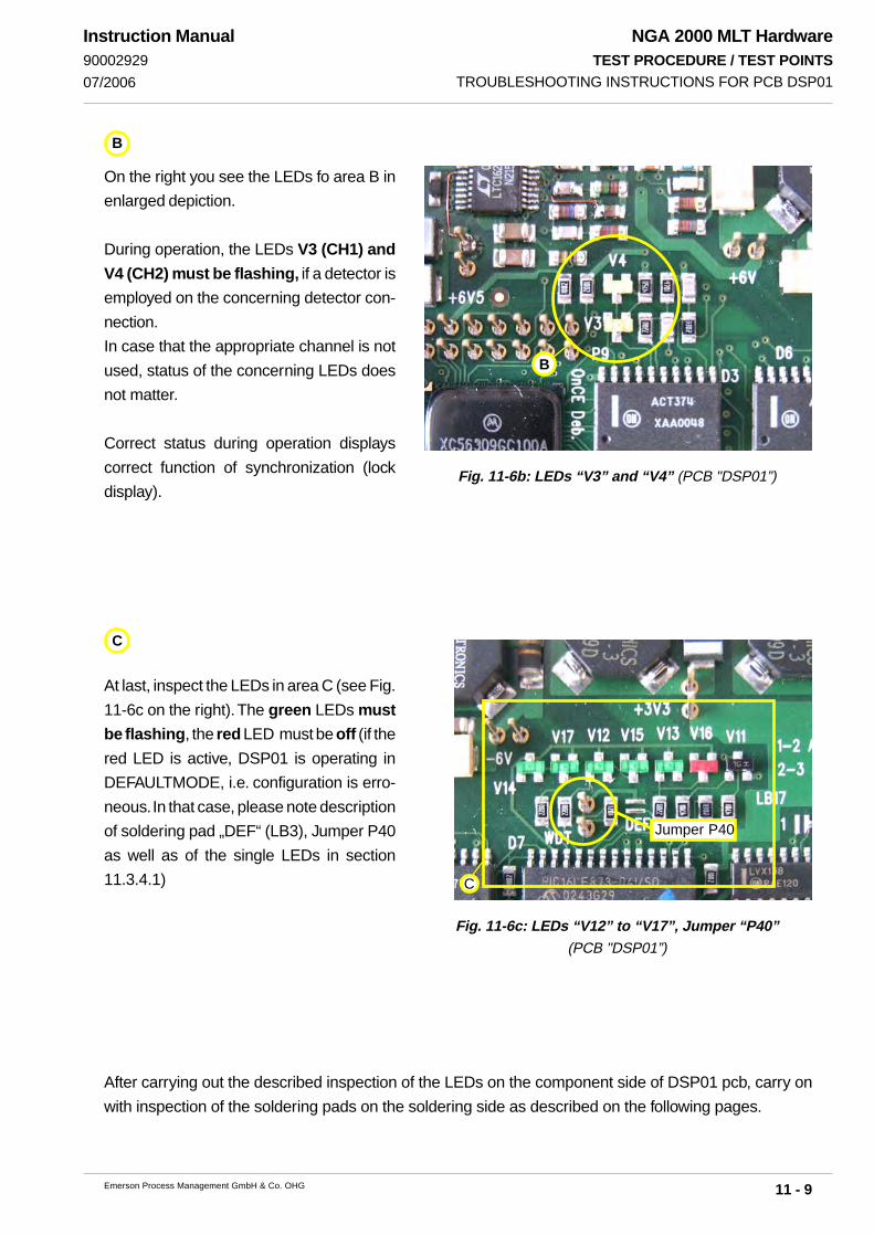
NGA 2000 MLT HardwareTEST PROCEDURE / TEST POINTS
11 - 9Emerson Process Management GmbH & Co. OHG
Instruction Manual90002929
07/2006
B
C
Jumper P40
B
C
On the right you see the LEDs fo area B in
enlarged depiction.
During operation, the LEDs V3 (CH1) and
V4 (CH2) must be flashing, if a detector is
employed on the concerning detector con-
nection.
In case that the appropriate channel is not
used, status of the concerning LEDs does
not matter.
Correct status during operation displays
correct function of synchronization (lock
display).
At last, inspect the LEDs in area C (see Fig.
11-6c on the right). The green LEDs must
be flashing, the red LED must be off (if the
red LED is active, DSP01 is operating in
DEFAULTMODE, i.e. configuration is erro-
neous. In that case, please note description
of soldering pad „DEF“ (LB3), Jumper P40
as well as of the single LEDs in section
11.3.4.1)
After carrying out the described inspection of the LEDs on the component side of DSP01 pcb, carry on
with inspection of the soldering pads on the soldering side as described on the following pages.
Fig. 11-6b: LEDs “V3” and “V4” (PCB "DSP01”)
Fig. 11-6c: LEDs “V12” to “V17”, Jumper “P40”(PCB "DSP01”)
TROUBLESHOOTING INSTRUCTIONS FOR PCB DSP01
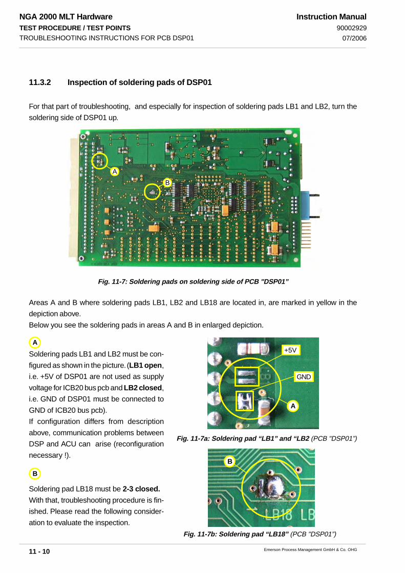
NGA 2000 MLT HardwareTEST PROCEDURE / TEST POINTS
11 - 10 Emerson Process Management GmbH & Co. OHG
Instruction Manual90002929
07/2006
A
+5V
GND
B
A
B
AB
11.3.2 Inspection of soldering pads of DSP01
For that part of troubleshooting, and especially for inspection of soldering pads LB1 and LB2, turn the
soldering side of DSP01 up.
Fig. 11-7: Soldering pads on soldering side of PCB "DSP01”
Areas A and B where soldering pads LB1, LB2 and LB18 are located in, are marked in yellow in the
depiction above.
Below you see the soldering pads in areas A and B in enlarged depiction.
Soldering pads LB1 and LB2 must be con-
figured as shown in the picture. (LB1 open,
i.e. +5V of DSP01 are not used as supply
voltage for ICB20 bus pcb and LB2 closed,
i.e. GND of DSP01 must be connected to
GND of ICB20 bus pcb).
If configuration differs from description
above, communication problems between
DSP and ACU can arise (reconfiguration
necessary !).
Soldering pad LB18 must be 2-3 closed.
With that, troubleshooting procedure is fin-
ished. Please read the following consider-
ation to evaluate the inspection.
Fig. 11-7a: Soldering pad “LB1” and “LB2 (PCB "DSP01”)
Fig. 11-7b: Soldering pad “LB18” (PCB "DSP01”)
TROUBLESHOOTING INSTRUCTIONS FOR PCB DSP01

NGA 2000 MLT HardwareTEST PROCEDURE / TEST POINTS
11 - 11Emerson Process Management GmbH & Co. OHG
Instruction Manual90002929
07/2006
Inspection of the LEDs (acc.to part 1 of this description)as well as LB3
Status of LEDs all right / LB3 all right(acc. to description)
DSP okay
Status of LEDs noterroneus(acc. to description)
Inspection of soldering padsLB1, LB2, LB18 and P40(acc. to description)
Probably there is aproblem with the DSP01pcb !
Correct configuration ofsoldering pads(acc. to description)
Incorrect configuration ofsoldering pads
Reconfiguration of solde-ring pads is necessary.
11.3.3 Evaluation
When inspection of the DSP is finished you can evaluate it as follows:
(Schematic diagram of inspection)
Fig. 11-8: Schematic diagram of inspection of PCB "DSP01”
TROUBLESHOOTING INSTRUCTIONS FOR PCB DSP01

NGA 2000 MLT HardwareTEST PROCEDURE / TEST POINTS
11 - 12 Emerson Process Management GmbH & Co. OHG
Instruction Manual90002929
07/2006
C
Soldering pad
11.3.4.2 Definition of
LEDs:
Both of the following tables con-
tain definitions of LEDs as well as
the Default configurations of
the soldering pads.
Mode LB3 LB18 P40Default close 2-3 x
LED OK Comment ErrorV16 on always on or offV13 off always on or offV15 flash MAX1400(DC) on or offV12 flash F Sensors on or offV17 flash Source current on or offV14 flash Chopper on or off
V3 flash Ch_signal 1 on or offV4 flash Ch_signal 2 on or offV7 flash Ch_signal 3 on or offV9 flash Ch_signal 4 on or off
11.3.4 Appendix
11.3.4.1 Description of soldering pad DEF (LB3):
Basically, soldering pad LB3 / DEF must be open.
Configuration of that soldering pad causes the following operating modes:
open: closed:
„NORMAL-MODE“ „DEFAULT-MODE“.
Table 11-1: Definition of LEDs/Default configuration of solderingpads (PCB "DSP01”)
Fig. 11-9: Soldering pad “DEF/LB3” (PCB "DSP01”)
TROUBLESHOOTING INSTRUCTIONS FOR PCB DSP01

NGA 2000 MLT HardwareTEST PROCEDURE / TEST POINTS
11 - 13Emerson Process Management GmbH & Co. OHG
Instruction Manual90002929
07/2006
Mode LB3 LB18 P40
Normal open
2-3(flash enable 1-2(for programm-
update), must be2-3)
open
LED OK Comment ErrorV16 off always on or off
V13 flashT / P Sensors(Pressure- andTemp. sensor)
on or off
V15 flashMAX1400(DC)A/D-converter(DC channels)
on or off
V12 flashF Sensors
(Flowsensors)
on or off
V17 flash Source current on or offV14 flash Chopper on or off
V3 flash Ch_signal 1(Detector 1) on or off
V4 flash Ch_signal 2(Detector 2) on or off
V7 flash Ch_signal 3(Detector 3) on or off
V9 flash Ch_signal 4(Detector 4) on or off
Table 11-2: Definition of LEDs/Normal configuration of soldering pads (PCB "DSP01”)
TROUBLESHOOTING INSTRUCTIONS FOR PCB DSP01

NGA 2000 MLT HardwareTEST PROCEDURE / TEST POINTS
11 - 14 Emerson Process Management GmbH & Co. OHG
Instruction Manual90002929
07/2006
NGA 2000 MLT HardwareREMOVAL / REPLACEMENT OF COMPONENTS
12 - 1Emerson Process Management GmbH & Co. OHG
Instruction Manual90002929
07/2006
12. Removal / Replacement of Components
Exchange components if requested by repair or servicing
Take care of the safety instructions as given at the beginning of this manualwhile working at and inside the instruments!
Working inside the instruments is subject to briefed personnel familiar withpotential risks!
12.1 Removal / Replacement of PCBs (in preparation)
12.1.1 Rear Mounting Slots (in preparation)
12.1.2 Internal Slots (in preparation)
REMOVAL OF OF PCBS (IN PREPARATION)
HIGH TEMPERATURES !While working at photometers and/or thermostated components inside theanalyzers hot components may be accessible!

NGA 2000 MLT HardwareREMOVAL / REPLACEMENT OF COMPONENTS
12 - 2 Emerson Process Management GmbH & Co. OHG
Instruction Manual90002929
07/2006
12.2 Removal / Replacement of Operation Front Panel
Front panel plate together with LC display and circuit board AFP 01 constitutes an unit. Therefore,
the front panel has to be disassembled completely when one component of the unit is out of order.
Take care of the safety instructions as given at the beginning of this manualwhile working at and inside the instruments!
Working inside the instruments is subject to briefed personnel familiar withpotential risks!
Open the front panel / housing (cf. Section 15).
Remove the cable (ACU - AFP 01 connection) from the circuit board ACU.
Remove all optional mounted components from front panel.
Exchange complete front panel unit .
Assemble all optional mounted components to new front panel.
Re-attach the cable (ACU - AFP 01 connection) to the circuit board ACU.
Close the instrument (i.e., re-attach the front panel, see section 15.).
REMOVAL / REPLACEMENT OF OPERATION FRONT PANEL

NGA 2000 MLT HardwareREMOVAL / REPLACEMENT OF COMPONENTS
12 - 3Emerson Process Management GmbH & Co. OHG
Instruction Manual90002929
07/2006
12.3 Replacement of Buffer Battery on the ACU 02
Take care of the safety instructions as given at the beginning of this manualwhile working at and inside the instruments!
Working inside the instruments is subject to briefed personnel familiar withpotential risks!
12.3.1 Removal of ACU 02
Use the following steps to remove the ACU 02 board (see Fig. 1-31, too):
Open the front panel / housing (cf. Section 15).
For analyzers:
Remove the cable (ACU - AFP 01 connection) from the circuit board ACU 02.
Push the card ejector for the ACU 02 downwards and remove the board.
REPLACEMENT OF BUFFER BATTERY OF ACU 02
Fig. 12-1: Controller Board ACU (partial view, component side)
Battery Jumper
(ACU 01: P17 / ACU 02: P23)
Connection
to LCD dispaly
+
Buffer battery
on soldering pins-
(AC
U01
: P17
/
AC
U02
: P23
)
(ACU01: P28 /
ACU02: P1)
(ACU01: P27 /
ACU02: P20)

NGA 2000 MLT HardwareREMOVAL / REPLACEMENT OF COMPONENTS
12 - 4 Emerson Process Management GmbH & Co. OHG
Instruction Manual90002929
07/2006
12.3.2 Replacement of Buffer Battery
Use the following procedure to replace the battery:
Remove the ACU 02 (see 12.3.1).
Remove the jumper “P23” (ACU02) or “P17” (ACU 01) for battery buffer (Fig. 12-1).
All data and compensation values entered by the user will be deleted (RAM-fail)!
Unsolder the battery from the soldering pins (see Fig. 12-1).
Solder the new battery (Ordering No. 03 765 180) to the soldering pins (see Fig. 12-1).
Verify polarity when soldering the new battery (Fig. 12-1) !Do not short circuit battery !
After the replacement:
Re-insert the jumper for battery buffer (Fig. 12-1).
Install the ACU 02 (see 12.3.3).
12.3.3 Installation of ACU 02
Tilt the card ejector of the ACU 02 upwards and put in the card until the catch locks into
place.
Re-attach the cable (ACU 02 - AFP 01 connection) to the circuit board ACU 02.
Close the instrument (i.e., re-attach the front panel, see section 15.).
Switch on instrument.
Now all the data required by the user can be entered again, e.g. system parameters.
REPLACEMENT OF BUFFER BATTERY OF ACU 02

NGA 2000 MLT HardwareREMOVAL / REPLACEMENT OF COMPONENTS
12 - 5Emerson Process Management GmbH & Co. OHG
Instruction Manual90002929
07/2006 FUSES
12.4 Fuses
Take care of the safety instructions as given at the beginning of this manualwhile working at and inside the instruments!
Working inside the instruments is subject to briefed personnel familiar withpotential risks!
In case of exchanging fuses the customer has to be certain that fuses ofspecified type and rated current are used. It is prohibited to use repairedfuses or defective fuse holders or to short-circuit fuse carriers (fire haz-ard).
After visual checking, check the fuses with an ohmmeter.
If low impedance has been measured, the fuse is in order.
High impedance means, the fuse is out of order and must be replaced.
12.4.1 MLT 2
Open the housing (cf. Section 15.2).
Take out and check the fuses (Fig. 12-2 and 1-15a).
Replace the fuse(s) if necessary [T 6.3 A / 250 V (5 x 20 mm)].
Close the housing (cf. Section 15.2).
Fig. 12-2: Fuses MLT 2 (partial inside view, drawing without front panel)
21
X11X9
1 1
Fuses (T 6.3A/250V)

NGA 2000 MLT HardwareREMOVAL / REPLACEMENT OF COMPONENTS
12 - 6 Emerson Process Management GmbH & Co. OHG
Instruction Manual90002929
07/2006FUSES
Fig. 12-3a: Fuses PCB LEM 01 (component side)
Fig. 12-3b: Fuses PCB LEM 02 (component side)
12.4.2 MLT 1 / 4
The fuses for 24 V dc Input are mounted on the PCB “LEM”.
Remove PCB “LEM” (see Section 12.1).
Take out and check the fuses (Fig. 12-3). Replace the fuse(s) if necessary.
Two pieces of spare fuses are on the PCB (Fig. 12-3).
Insert PCB “LEM” (see Section 12.1) and reclose the instrument.
Network
Connectors
(RJ 45)
Fuse
Network
Connectors
(RJ 45)
Fuse
Spare Fuses
Spare Fuses

NGA 2000 MLT HardwareREMOVAL / REPLACEMENT OF COMPONENTS
12 - 7Emerson Process Management GmbH & Co. OHG
Instruction Manual90002929
07/2006
12.5 Connect / Disconnect UV Source and Power Supply for UV Source
The cover of the housing and the front panel plate has to be disassembled to have access to
the cable from the UV source to connect it with the power supply for UV source.
CONNECT/DISCONNECT UV SOURCE AND POWER SUPPLY FOR UV SOURCE
UV SOURCE !Ultraviolet light from UV lamp can cause permanent eye damage !Do not look directly at the ultraviolet source !
The optional UV lamp operates with high voltage (Power Supply UVS) !HIGH VOLTAGE !
TOXIC SUBSTANCE !The optional UV lamp contains mercury. Lamp breakage couldresult in mercury exposure ! Mercury is highly toxic !If the lamp is broken, avoid any skin contact to mercury andinhalation of mercury vapors !
Take care of the safety instructions as given at the beginning of this manualwhile working at and inside the instruments!
Working inside the instruments is subject to briefed personnel familiar withpotential risks!

NGA 2000 MLT HardwareREMOVAL / REPLACEMENT OF COMPONENTS
12 - 8 Emerson Process Management GmbH & Co. OHG
Instruction Manual90002929
07/2006CONNECT/DISCONNECT UV SOURCE AND POWER SUPPLY FOR UV SOURCE
Fig. 12-4a: Power Supply for UV Source (front view, front panel disassembled)
Open the front panel / remove cover from MLT housing (cf. Section 15).
Take the cable from the UV source (part no. 42711213) out of the thermostat controlled
compartment to the power supply for UV source located behind the removed front panel
Plug in the cable from UV source on the connector on top of the power supply for UV
source (part no. 42715072).
Plug in cable from UV sourcePower Supply for UV Source

NGA 2000 MLT HardwareREMOVAL / REPLACEMENT OF COMPONENTS
12 - 9Emerson Process Management GmbH & Co. OHG
Instruction Manual90002929
07/2006
Connect the two white grounding cables to the UV source.
One grounding cable comes from power supply for UV source .
The 2nd grounding cables comes from PCB ESP10 (part no. 43002530).
Connect both cables to the UV lamp (connection point) as indicated below.
Fig. 12-4b: UV Source and PCB ESP10 (top view, housing cover disassembled)
CONNECT/DISCONNECT UV SOURCE AND POWER SUPPLY FOR UV SOURCE
PCB ESP10 UV Source
Cable from UV source to UV power supply
Connection point at UV source

NGA 2000 MLT HardwareREMOVAL / REPLACEMENT OF COMPONENTS
12 - 10 Emerson Process Management GmbH & Co. OHG
Instruction Manual90002929
07/2006

13 - 1
NGA 2000 MLT HardwareMAINTENANCE
Emerson Process Management GmbH & Co. OHG
Instruction Manual90002929
07/2006
Maintenance
In general only the gas conditionning hardware will require maintenance; the analyzer itself
requires very little maintenance.
The following checks are recommended for maintenance of the proper operation of the analyzer.
Check and adjust zero-level: weekly
(MLT 1ULCO / MLT 3 Gas Purity Measurment: daily)
Check and adjust span: weekly
(MLT 1ULCO / MLT 3 Gas Purity Measurment: daily)
Perform leak testing: 6 times annually.
The maintenance frequencies stated above are presented as guidelines only; maintenance
operations may be required more or less frequently, depending upon usage and site conditions.

13 - 2
NGA 2000 MLT HardwareMAINTENANCE
Emerson Process Management GmbH & Co. OHG
Instruction Manual90002929
07/2006

14 - 1
NGA 2000 MLT HardwareLEAK TESTING
Emerson Process Management GmbH & Co. OHG
Instruction Manual9000292907/2006
Fig. 14-1: Leak Testing with an U - Tube - Manometer
Required tools• U-turn manometer for max. 500 hPa• Stop valve
Procedure• Connect the water filled u-turn manometer to the analyzer‘s sample gas output
(disconnect external gas lines).• Install the stop valve between gas input fitting and a Nitrogen (N2) supply.• Open the stop valve until the internal gas path is under pressure of approx. 50 hPa
(corresponding to 500 mm water column)• Close the stop valve. After a short time for the water to balance the water level
must not change over a time period of approx. 5 minutes!
Note!It is recommended to include external equipment (e.g. cooler, dust filters, etc.) into a leaktest!
Overpressure max. 500 hPa !For differential measurement the leakage check must be performed formeasurement side and reference side separately !Analyzers with parallel tubing require separate leak tests for each gas path!
14. Leak Testing
The gas path system should be leak tested at least on a bimonthly basis and after maintenance,replacement or repair of gas path parts.
Before opening gas paths they must be purged with ambient air orneutral gas (N2) to avoid hazards caused by toxic, flammable,explosive or harmful to health sample gas components!
Analyzer /Analyzer Module
Overpres-sure
Valve
Water

14 - 2
NGA 2000 MLT HardwareLEAK TESTING
Emerson Process Management GmbH & Co. OHG
Instruction Manual90002929
07/2006

NGA 2000 MLT HardwareOPENING OF HOUSING
15 - 1Emerson Process Management GmbH & Co. OHG
Instruction Manual9000292907/2006
15. Opening the Housing
The housing must be opened for checking the electrical connections and for replacement orcleaning of any of the components of the analyzer.The following sections describe how to open the different analyzer housings provided theinstruments are fully accessible, e.g. are taken out of the rack.
MLT 1
Before opening gas paths they must be purged with ambient air orneutral gas (N2) to avoid hazards caused by toxic, flammable,explosive or harmful to health sample gas components!
HIGH TEMPERATURES !While working at photometers and/or thermostated components inside theanalyzers hot components may be accessible!
ELECTRICAL SHOCK HAZARD!Live parts are accessible when working at open instruments!
Take care of the safety instructions as given at the beginning of this manualwhile working at and inside the instruments!
Working inside the instruments is subject to briefed personnel familiar withpotential risks!

NGA 2000 MLT HardwareOPENING OF HOUSING
15 - 2 Emerson Process Management GmbH & Co. OHG
Instruction Manual90002929
07/2006
15.1 MLT 1
15.1.1 MLT 1 (Platform housing)
15.1.1.1 Housing Cover
Disconnect all voltage supplies.
Remove analyzer module out of platform (see platform manual).
Unscrew the respective fastening screws at both housing sides (Fig. 15-1).
For rear cover unscrew the additonal fastening screw at the top of the housing (Fig. 15-1)
Remove the respective housing top cover panel.
Repeat above steps in reverse order to assemble the housing
Fig. 15-1: MLT 1 (Plattform housing)(Fastening screws housing cover)
MLT 1 (PLATFORM HOUSING)
Fastening screw,front housing cover
Top fastening screws,rear housing cover
Fastening screw,rear housing cover

NGA 2000 MLT HardwareOPENING OF HOUSING
15 - 3Emerson Process Management GmbH & Co. OHG
Instruction Manual9000292907/2006
15.1.1.2 Front Panel
Removing of front panel can be done without removing of housing covers:
Disconnect module from power supply.
Remove analyzer module out of platform (Item 17.1 of platform manual).
Unscrew the 6 fastening screws at both housing sides (Fig. 15-2)or
unscrew the 4 fastening screws at front panel (Fig. 15-2).
Remove front panel to the front carefully.
Optionally internal components may be fixed to the front panel, e.g. inter-nal fan, UVS, oxygen sensor, pressure sensor (see fig. 1-7)!
Repeat above steps in reverse order to assemble the housing
Take care not to squeeze internal electrical connections and gas lines whenassembling the housing!
Fig. 15-2: MLT 1 (Plattform housing)(Fastening screws front panel)
MLT 1 (PLATFORM HOUSING)
Fastening screw,front housing cover
Fastening screws,module front panel
Fastening screws,module front panel

NGA 2000 MLT HardwareOPENING OF HOUSING
15 - 4 Emerson Process Management GmbH & Co. OHG
Instruction Manual90002929
07/2006
15.1.2 MLT 1 (1/2 19" housing)
15.1.2.1 Housing Cover
Disconnect all voltage supplies.
Unscrew fastening screws for rack mounting / front frame if necessary (Fig. 1-1).Remove analyzer out of rack or remove the front mounting frame and carrying strap to rear.
Unscrew the respective fastening screws at both housing sides (Fig. 15-3)
Remove the respective housing top cover panel.
Repeat above steps in reverse order to assemble the housing
Fig. 15-3: MLT 1 (1/2 19" housing)(Fastening screws housing cover)
MLT 1 (1/2 19" HOUSING)
fastening screws housing cover

NGA 2000 MLT HardwareOPENING OF HOUSING
15 - 5Emerson Process Management GmbH & Co. OHG
Instruction Manual9000292907/2006
15.1.2.2 Front Panel
Opening housing cover (Item 15.2.1).
Unscrew the 6 fastening screws at both housing sides (Fig. 15-4)
Remove front panel to the front carefully.
Optionally internal components may be fixed to the front panel, e.g. inter-nal fan, UVS, oxygen sensor, pressure sensor (see fig. 1-7)!
Repeat above steps in reverse order to assemble the housing
Take care not to squeeze internal electrical connections and gas lines whenassembling the housing!
MLT 1 (1/2 19" HOUSING)
Fig. 15-4: MLT 1 (1/2 19" housing)(Fastening screws front panel)
Fastening screws,front panel
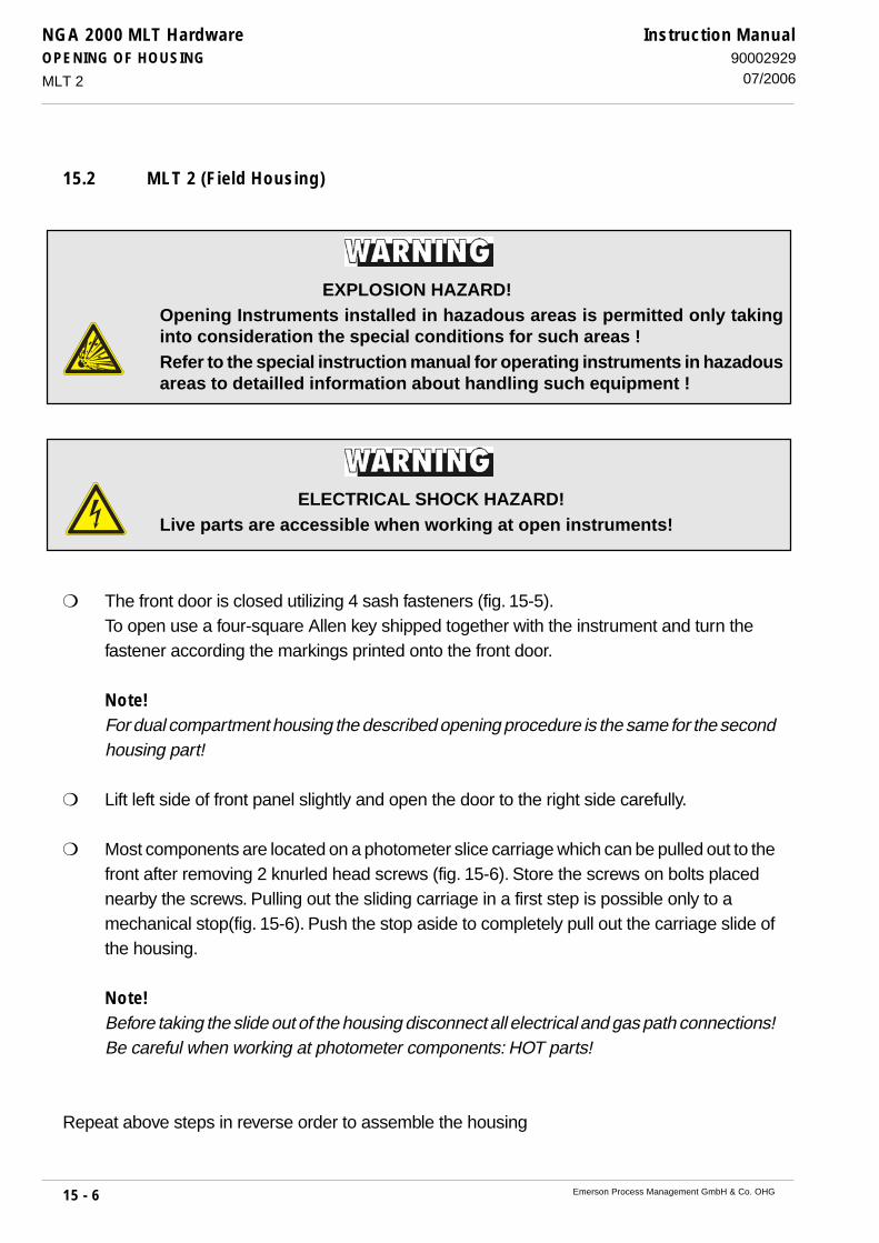
NGA 2000 MLT HardwareOPENING OF HOUSING
15 - 6 Emerson Process Management GmbH & Co. OHG
Instruction Manual90002929
07/2006
15.2 MLT 2 (Field Housing)
The front door is closed utilizing 4 sash fasteners (fig. 15-5).To open use a four-square Allen key shipped together with the instrument and turn thefastener according the markings printed onto the front door.
Note!For dual compartment housing the described opening procedure is the same for the secondhousing part!
Lift left side of front panel slightly and open the door to the right side carefully.
Most components are located on a photometer slice carriage which can be pulled out to thefront after removing 2 knurled head screws (fig. 15-6). Store the screws on bolts placednearby the screws. Pulling out the sliding carriage in a first step is possible only to amechanical stop(fig. 15-6). Push the stop aside to completely pull out the carriage slide ofthe housing.
Note!Before taking the slide out of the housing disconnect all electrical and gas path connections!Be careful when working at photometer components: HOT parts!
Repeat above steps in reverse order to assemble the housing
MLT 2
EXPLOSION HAZARD!Opening Instruments installed in hazadous areas is permitted only takinginto consideration the special conditions for such areas !Refer to the special instruction manual for operating instruments in hazadousareas to detailled information about handling such equipment !
ELECTRICAL SHOCK HAZARD!Live parts are accessible when working at open instruments!

NGA 2000 MLT HardwareOPENING OF HOUSING
15 - 7Emerson Process Management GmbH & Co. OHG
Instruction Manual9000292907/2006
Fig. 15-5: MLT 2 (Field housing) (fastener for front panel)
Fig. 15-6: MLT 2, photometer carriage slide
MLT 2
Fastener for front panel
Fastener for front panel
knurled head screws
mechanicalstop
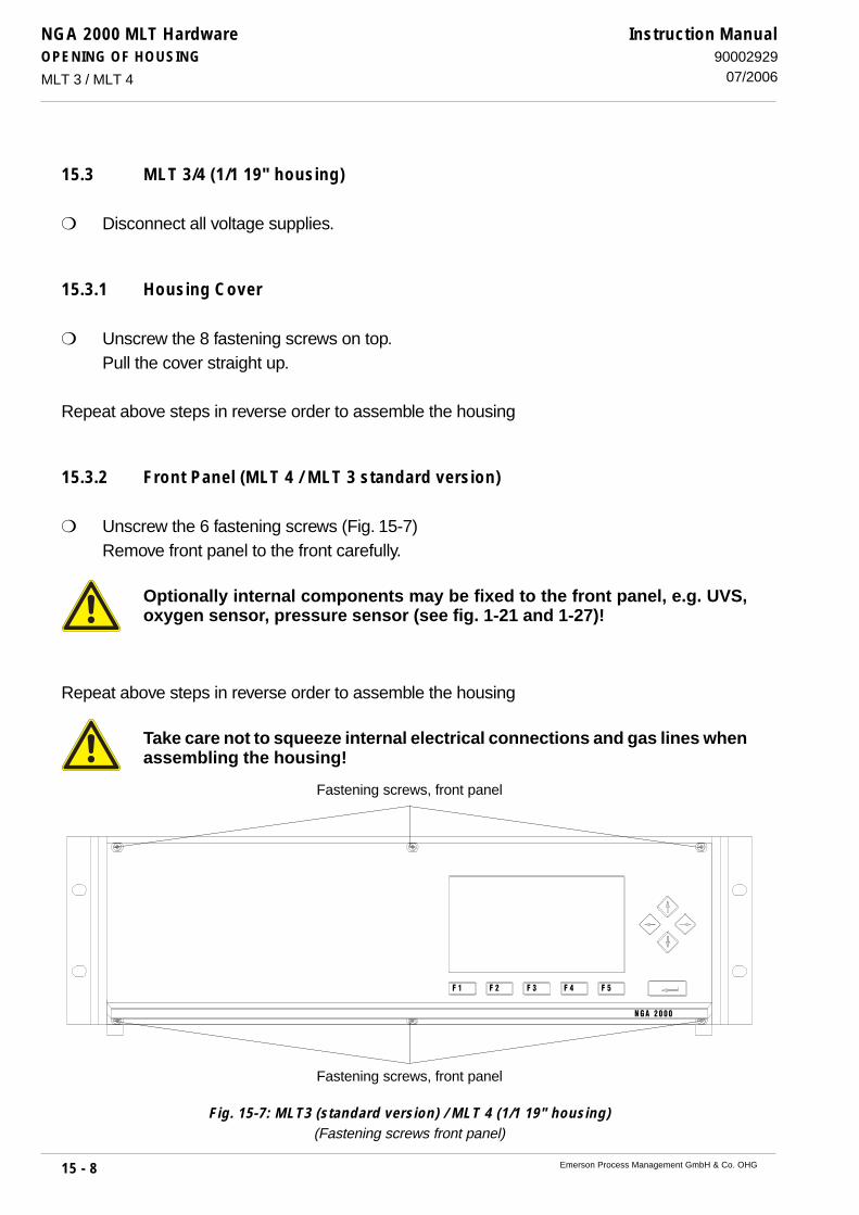
NGA 2000 MLT HardwareOPENING OF HOUSING
15 - 8 Emerson Process Management GmbH & Co. OHG
Instruction Manual90002929
07/2006
15.3 MLT 3/4 (1/1 19" housing)
Disconnect all voltage supplies.
15.3.1 Housing Cover
Unscrew the 8 fastening screws on top.Pull the cover straight up.
Repeat above steps in reverse order to assemble the housing
15.3.2 Front Panel (MLT 4 / MLT 3 standard version)
Unscrew the 6 fastening screws (Fig. 15-7)Remove front panel to the front carefully.
Optionally internal components may be fixed to the front panel, e.g. UVS,oxygen sensor, pressure sensor (see fig. 1-21 and 1-27)!
Repeat above steps in reverse order to assemble the housing
Take care not to squeeze internal electrical connections and gas lines whenassembling the housing!
Fig. 15-7: MLT3 (standard version) / MLT 4 (1/1 19" housing)(Fastening screws front panel)
MLT 3 / MLT 4
Fastening screws, front panel
Fastening screws, front panel

NGA 2000 MLT HardwareOPENING OF HOUSING
15 - 9Emerson Process Management GmbH & Co. OHG
Instruction Manual9000292907/2006 MLT 3 FOR GAS PURITY MEASUREMENT
15.3.3 Front Panel (MLT 3 gas purity measurement)
15.3.3.1 Operation Front Panel
Unscrew the 6 fastening screws (Fig. 15-8)Remove operation front panel to the front carefully.
15.3.3.2 Left Front Panel
Unscrew the 4 fastening screws (Fig. 15-8).Remove left front panel to the front carefully.
Gas lines and optionally internal components may be fixed to the frontpanel (see fig. 1-24)!
Repeat above steps in reverse order to assemble the housing
Take care not to squeeze internal electrical connections and gas lines whenassembling the housing!
Fig. 15-8: MLT3 (gas purity measurement) (1/1 19" housing)(Fastening screws front panel)
Fastening screws, operation front panel
Fastening screws, operation front panel
Rosemount Analytical NGA 2000
F3 F4 F5F2F1
Fastening screws, left front panel
Fastening screws, left front panel

NGA 2000 MLT HardwareOPENING OF HOUSING
15 - 10 Emerson Process Management GmbH & Co. OHG
Instruction Manual90002929
07/2006
15.4 CAT 200
EXPLOSION HAZARD!Opening Instruments installed in hazadous areas is permitted only takinginto consideration the special conditions for such areas !Refer to the special instruction manual for operating instruments in hazadousareas to detailled information about handling such equipment !
ELECTRICAL SHOCK HAZARD!Live parts are accessible when working at open instruments!
HEAVY PARTS!Individual housing components weigh up to 27 kg !Dome components slip off when reaching end of threat !Use suitable tools or work in pairs !
CAT 200

NGA 2000 MLT HardwareOPENING OF HOUSING
15 - 11Emerson Process Management GmbH & Co. OHG
Instruction Manual9000292907/2006
The CAT 200 housing consists of two main parts:• junction box• dome with extender housing
Fig. 15-9: Cat 200 Enclosure Assembly
The junction box contains an encapsulated EMI mains filter and all the terminals for connectingmains supply and signal lines. The dome covers all other components, e.g. power supply unit andanalyzer module.
CAT 200
Extender Housing
Dome Housing
O-Ring
O-Ring
Retaining Ring
Window
Base

NGA 2000 MLT HardwareOPENING OF HOUSING
15 - 12 Emerson Process Management GmbH & Co. OHG
Instruction Manual90002929
07/2006
15.4.1 Junction Box
Open the junction box by loosening the 6 Allen screws (fig. 15-10) utilizing the (imperial) Allenkey shipped with the instrument.
Remove the cover.
Note!Assemble the cover utilizing ALL 6 screws to ensure proper IP rating against dust andwater!
Fig. 15-10: Cat 200 Junction box
CAT 200
Allen screws (6 pcs)

NGA 2000 MLT HardwareOPENING OF HOUSING
15 - 13Emerson Process Management GmbH & Co. OHG
Instruction Manual9000292907/2006
15.4.2 Dome
To get access to internal components and the analyzer module the dome‘s components have tobe removed (fig. 15-11):
Loosen the outer screw
Turn the dome counterclockwise to remove it
Loosen the inner screw
Turn the extender ring counterclockwise to remove it
Fig. 15-11: CAT 200 Dome, fixing screws
When dome is removed unscrew the knurled head screws at the analyzer module‘s sides(fig. 15-12) and pull it to the front until the last screw locks into the detent (fig. 15-13).
Note!Mark or remember the detent where the first knurled head screw was placed, to place it thereagain when assembling the unit!Otherwise it may happen the analyzer is not magnetically operable any more because thedistance between front panel and glass it to great.
CAT 200
Screws fixing domecomponents
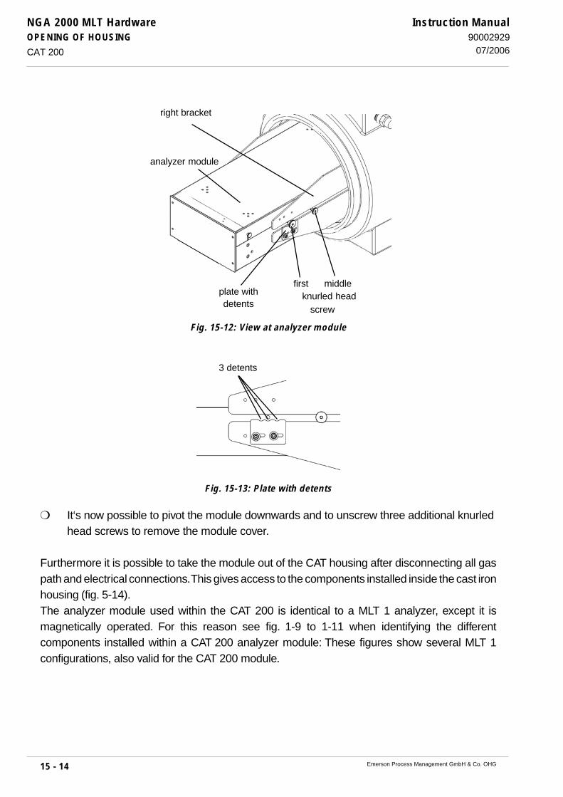
NGA 2000 MLT HardwareOPENING OF HOUSING
15 - 14 Emerson Process Management GmbH & Co. OHG
Instruction Manual90002929
07/2006
Fig. 15-13: Plate with detents
It‘s now possible to pivot the module downwards and to unscrew three additional knurledhead screws to remove the module cover.
Furthermore it is possible to take the module out of the CAT housing after disconnecting all gaspath and electrical connections. This gives access to the components installed inside the cast ironhousing (fig. 5-14).The analyzer module used within the CAT 200 is identical to a MLT 1 analyzer, except it ismagnetically operated. For this reason see fig. 1-9 to 1-11 when identifying the differentcomponents installed within a CAT 200 analyzer module: These figures show several MLT 1configurations, also valid for the CAT 200 module.
CAT 200
Fig. 15-12: View at analyzer module
first middleknurled head
screw
plate withdetents
analyzer module
right bracket
3 detents
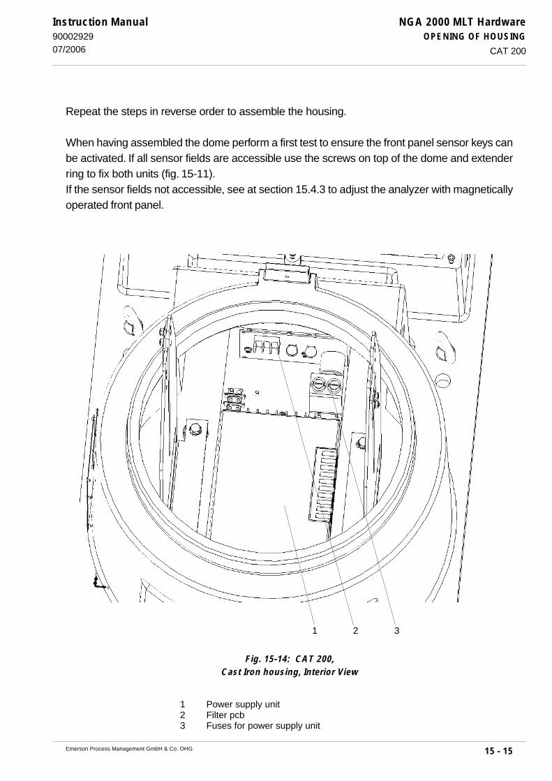
NGA 2000 MLT HardwareOPENING OF HOUSING
15 - 15Emerson Process Management GmbH & Co. OHG
Instruction Manual9000292907/2006
Fig. 15-14: CAT 200,Cast Iron housing, Interior View
1 Power supply unit2 Filter pcb3 Fuses for power supply unit
Repeat the steps in reverse order to assemble the housing.
When having assembled the dome perform a first test to ensure the front panel sensor keys canbe activated. If all sensor fields are accessible use the screws on top of the dome and extenderring to fix both units (fig. 15-11).If the sensor fields not accessible, see at section 15.4.3 to adjust the analyzer with magneticallyoperated front panel.
CAT 200
1 2 3

NGA 2000 MLT HardwareOPENING OF HOUSING
15 - 16 Emerson Process Management GmbH & Co. OHG
Instruction Manual90002929
07/2006
15.4.3 Magnetically Operated Front Panel
To ensure safe and faultless operation of the touch panel it is required to have the control elements(reed relays) installed within a defined distance from the inner side of the security glass.If it is necessary to remove the CAT 100 dome for maintenance and/or inspection purposes andto loosen the internal analyzer, the following measures must be followed:
15.4.3.1 Sliding the Analyzer into Position
Set the analyzer module onto the fixture.Position the dome and fix it turning it clockwise. The inner side of the front glass now should havecontact to the analyzers key pad bar and push the analyzer into the CAT housing.The front of the key pad bar should now have a distance from the inner side of the dome’s frontglass of between 0 and max. 2 mm (fig. 15-15).If the distance is bigger, it has to be corrected by repeating the procedure.Next remove the CAT dome once more.
15.4.3.2 Fixing the Analyzer
Fix the analyzer on the fixture using the screws located at the analyzers left and right side.
15.4.3.3 Completing the Adjustment
Postion the CAT dome and fix it. Make sure the distance is still correct.
CAT 200
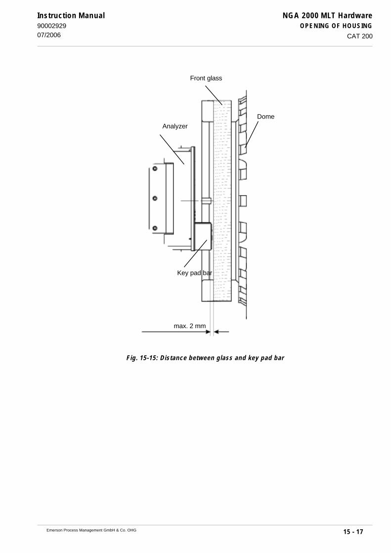
NGA 2000 MLT HardwareOPENING OF HOUSING
15 - 17Emerson Process Management GmbH & Co. OHG
Instruction Manual9000292907/2006
Fig. 15-15: Distance between glass and key pad bar
CAT 200
Key pad bar
Front glass
Analyzer
Dome
max. 2 mm

NGA 2000 MLT HardwareOPENING OF HOUSING
15 - 18 Emerson Process Management GmbH & Co. OHG
Instruction Manual90002929
07/2006

NGA 2000 MLT HardwareFINE DUST FILTER (MLT 3 OPTION)
16 - 1Emerson Process Management GmbH & Co. OHG
Instruction Manual9000292907/2006
16. Fine Dust filter (MLT 3 Option)
The filter element of the in MLT 3 optional installed fine dust filter (see Fig. 1-16a) needs to be checkedfor pollution on a regular basis, depending on the application and to be replaced if need be. If thefilter element shows contamination, the element should be immediately replaced with a new unit.
Disconnect all voltage supplies.
Remove front panel (Item 15.3.2).
Removal of filter holder.
Replace the filter element by a new clean element (Order - No.: 42 707 676).
Filter elements are consumables!Never try to clean polluted elements! Use only new original spare parts forreplacing polluted elements!Dispose polluted filter elements taking into account the local legislation!
Reinstall filter holder.
Perform a leak testing (see Item 14.).
Close front panel (Item 15.3.2).
Before opening gas paths they must be purged with ambient air orneutral gas (N2) to avoid hazards caused by toxic, flammable,explosive or harmful to health sample gas components!
HIGH TEMPERATURES !While working at photometers and/or thermostated components inside theanalyzers hot components may be accessible!

NGA 2000 MLT HardwareFINE DUST FILTER (MLT 3 OPTION)
16 - 2 Emerson Process Management GmbH & Co. OHG
Instruction Manual90002929
07/2006
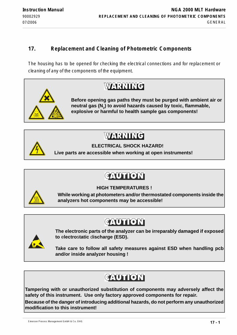
17 - 1
NGA 2000 MLT HardwareREPLACEMENT AND CLEANING OF PHOTOMETRIC COMPONENTS
Emerson Process Management GmbH & Co. OHG
Instruction Manual90002929
07/2006
17. Replacement and Cleaning of Photometric Components
The housing has to be opened for checking the electrical connections and for replacement or
cleaning of any of the components of the equipment.
GENERAL
Before opening gas paths they must be purged with ambient air orneutral gas (N2) to avoid hazards caused by toxic, flammable,explosive or harmful to health sample gas components!
Tampering with or unauthorized substitution of components may adversely affect thesafety of this instrument. Use only factory approved components for repair.Because of the danger of introducing additional hazards, do not perform any unauthorizedmodification to this instrument!
The electronic parts of the analyzer can be irreparably damaged if exposedto electrostatic discharge (ESD).
Take care to follow all safety measures against ESD when handling pcband/or inside analyzer housing !
HIGH TEMPERATURES !While working at photometers and/or thermostated components inside theanalyzers hot components may be accessible!
ELECTRICAL SHOCK HAZARD!Live parts are accessible when working at open instruments!

NGA 2000 MLT HardwareREPLACEMENT AND CLEANING OF PHOTOMETRIC COMPONENTS
17 - 2 Emerson Process Management GmbH & Co. OHG
Instruction Manual90002929
07/2006
Take care of the safety instructions as given at the beginning of this manualwhile working at and inside the instruments!
Working inside the instruments is subject to briefed personnel familiar withpotential risks!
17.1 Removal of the Photometer Assembly
Open the housing (cf. Section 15).
Disconnect all electrical connections between photometer assembly and electronic unit
(PCB PIC) and remove all gas lines from the photometer assembly if necessary.
Unscrew both the hexagonal screws shown in Fig. 17-1.
Remove the photometer assembly to top of analyzer housing as a unit.
REMOVAL OF THE PHOTOMETER ASSEMBLY
Fig. 17-1: Photometer Assembly, example(Top view, detail)
hexagonal screw
hexagonal screw

17 - 3
NGA 2000 MLT HardwareREPLACEMENT AND CLEANING OF PHOTOMETRIC COMPONENTS
Emerson Process Management GmbH & Co. OHG
Instruction Manual90002929
07/2006 LIGHT SOURCE REPLACEMENT
Fig. 17-2: Chopper Housing with IR light sources
1 Light source hexagonal mounting screw2 Light source with mounting flange3 Temperature sensor (older versions)4 Chopper Housing
4
17.2 Light Source Replacement (IR)
Open the housing (cf. Section 15).
Remove the photometer assembly out of analyzer housing (see Section 17.1).
Remove the two light source hexagonal mounting screws (shown in Fig. 17-2 as Item 1).
Remove the light source together with its mounting flange.
Remove the mounting flange from the light source and position it on the new light source.
Insert the new light source and flange in the same position as the old one.
Insert and tighten the two light source hexagonal mounting screws (Fig. 17-2).
Then:
Replace the photometer assembly (see Section 17.4).
Perform the physical zeroing procedure (see Section 17.5).
3
2
1
1
2
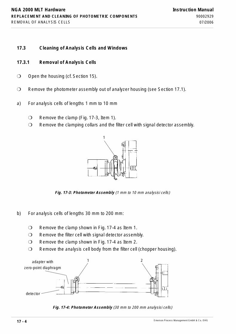
NGA 2000 MLT HardwareREPLACEMENT AND CLEANING OF PHOTOMETRIC COMPONENTS
17 - 4 Emerson Process Management GmbH & Co. OHG
Instruction Manual90002929
07/2006REMOVAL OF ANALYSIS CELLS
17.3 Cleaning of Analysis Cells and Windows
17.3.1 Removal of Analysis Cells
Open the housing (cf. Section 15).
Remove the photometer assembly out of analyzer housing (see Section 17.1).
a) For analysis cells of lengths 1 mm to 10 mm
Remove the clamp (Fig. 17-3, Item 1).
Remove the clamping collars and the filter cell with signal detector assembly.
Fig. 17-3: Photometer Assembly (1 mm to 10 mm analysisi cells)
b) For analysis cells of lengths 30 mm to 200 mm:
Remove the clamp shown in Fig. 17-4 as Item 1.
Remove the filter cell with signal detector assembly.
Remove the clamp shown in Fig. 17-4 as Item 2.
Remove the analysis cell body from the filter cell (chopper housing).
Fig. 17-4: Photometer Assembly (30 mm to 200 mm analysisi cells)
1
21
detector
adapter with
zero-point diaphragm
17 - 5
NGA 2000 MLT HardwareREPLACEMENT AND CLEANING OF PHOTOMETRIC COMPONENTS
Emerson Process Management GmbH & Co. OHG
Instruction Manual90002929
07/2006
17.3.2 Cleaning
a) Windows
The shielding windows (on the filter cells, chopper housing and the analysis cell) may be cleaned
with a soft, fluff free cloth.
Use a highly volatile alcohol for the cleaning procedure.
To remove any lint and dust particles remaining, blow off the cleaned components with nitrogen
(N2).
b) non-divided analysis cells
The analysis cell may be cleaned with a soft, fluff free cloth.
Use a highly volatile alcohol for the cleaning procedure.
To remove any lint and dust particles remaining, blow off analysis cell with nitrogen (N2).
c) divided analysis cells
If deposits are visible in the analysis cell, these can be removed with suitable solvents e. g. acetone
or spirit. Then the analysis cell is to be flushed with an alcohol which evaporates easily and dried
by blowing nitrogen (N2).
Maxi. pressure in analysis cell 1.500 hPa !
CLEANING

NGA 2000 MLT HardwareREPLACEMENT AND CLEANING OF PHOTOMETRIC COMPONENTS
17 - 6 Emerson Process Management GmbH & Co. OHG
Instruction Manual90002929
07/2006REINSTALLING OF ANALYSIS CELLS
17.3.3 Reinstalling of Analysis Cells
a) For analysis cells of lengths 1 mm and 7 mm
Place the O - rings on the filter cells.
Fit the components together and fix with the clamping collars.
Install the clamp (Fig. 17-3, Item 1) and tighten.
b) Analysis cells of lengths 50 mm - 200 mm:
Place the O - ring on the chopper housing side of the cell body.
Position the cell body in place and fasten using the clamp shown in Fig. 17-4 as
Item 2.
Place the O - ring on the filter cell (with detector).
Fit the filter cell on the cell body.
Install the clamp shown in Fig. 17-4 as Item 1 and tighten.
Then:
Replace the photometer assembly (see Section 17.4).

17 - 7
NGA 2000 MLT HardwareREPLACEMENT AND CLEANING OF PHOTOMETRIC COMPONENTS
Emerson Process Management GmbH & Co. OHG
Instruction Manual90002929
07/2006
17.4 Reinstalling of the Photometer Assembly
Insert the photometer assembly into the analyzer housing and fasten in position using
the hexagonal screws shown in Fig. 17-1.
Reconnect all gas lines to the assembly.
Reconnect all electrical connections between the photometer assembly and the electronic
unit PCB PIC (see Section 1.9.4).
Perform a leakage test (see Section 14).
Perform the physical zeroing procedure (see Section 17.5).
REINSTALLING OF THE PHOTOMETER ASSEMBLY
NGA 2000 MLT HardwareREPLACEMENT AND CLEANING OF PHOTOMETRIC COMPONENTS
17 - 8 Emerson Process Management GmbH & Co. OHG
Instruction Manual90002929
07/2006
17.5 Physical Zeroing
Adjustment of the physical zero - level will only be required if a light source, a filter cell, or an analysis
cell have been replaced or repositionned.
Needed for the adjustment is a 3 mm hexagon wrench SW 3.
Switch on the analyzer (cf. Section 6.).
Admit zero gas to the instrument.
Slightly loosen the light source mounting screws (shown in Fig. 17-2 as Item 1) for
correspondend channel.
Set the raw signal [(press "Status" (F2) → "RawMeas." (F2)] precisely to ± 100.000 counts
by turning the corresponding light source.
Tighten the light source mounting screws (shown in Fig. 17-2 as Item 1) for correspondend
channel.
If the turning of the light source is not sufficient, the zero point can be adjusted by sliding the zero
point diaphragm at the downer side of the detectors adapter (Fig. 17-4).
When the physical zeroing has been correctly set, perform an electrical zeroing (see software
manual).
PHYSICAL ZEROING
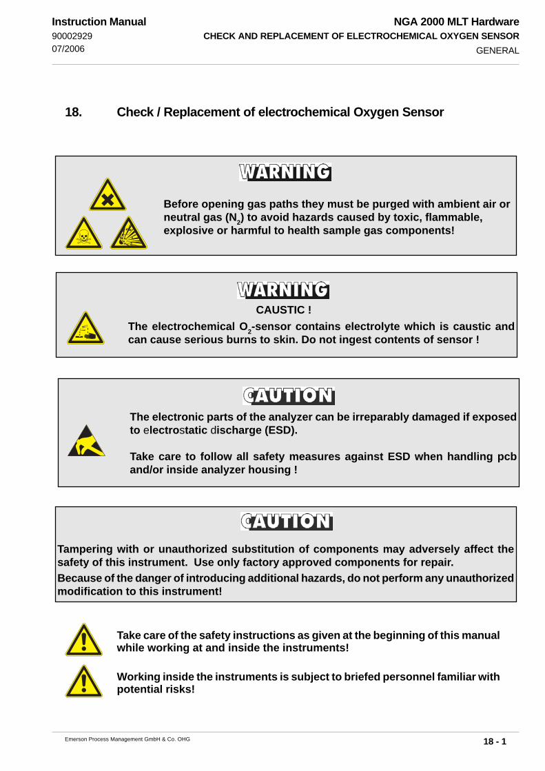
NGA 2000 MLT HardwareCHECK AND REPLACEMENT OF ELECTROCHEMICAL OXYGEN SENSOR
18 - 1Emerson Process Management GmbH & Co. OHG
Instruction Manual9000292907/2006
18. Check / Replacement of electrochemical Oxygen Sensor
Take care of the safety instructions as given at the beginning of this manualwhile working at and inside the instruments!
Working inside the instruments is subject to briefed personnel familiar withpotential risks!
GENERAL
Before opening gas paths they must be purged with ambient air orneutral gas (N2) to avoid hazards caused by toxic, flammable,explosive or harmful to health sample gas components!
The electrochemical O2-sensor contains electrolyte which is caustic andcan cause serious burns to skin. Do not ingest contents of sensor !
CAUSTIC !
Tampering with or unauthorized substitution of components may adversely affect thesafety of this instrument. Use only factory approved components for repair.Because of the danger of introducing additional hazards, do not perform any unauthorizedmodification to this instrument!
The electronic parts of the analyzer can be irreparably damaged if exposedto electrostatic discharge (ESD).
Take care to follow all safety measures against ESD when handling pcband/or inside analyzer housing !
NGA 2000 MLT HardwareCHECK AND REPLACEMENT OF ELECTROCHEMICAL OXYGEN SENSOR
18 - 2 Emerson Process Management GmbH & Co. OHG
Instruction Manual90002929
07/2006EO2-SENSOR
18.1 EO2-Sensor
Through measuring principle the oxygen sensor will have only a limited life time.
The life time of the oxygen sensor is dependent on the sensor itself and on the measured oxygenconcentration and is calculated as follows:
life time =
The so-called “sensor time” (operation without oxygen at 20 °C ) is
approx. 900.000 hours for sensor with a response time of about 12 s
The sensors will have the following life time at approx. 21 % Oxygen and 20 °C :
approx. 42.857 hours (approx. 5 years) for sensor with a response time of about 12 s
Note !The given values are for reference only! The expected lifetime is greatly affected by thetemperature of the environment in which the sensor is used or stored. Increases or decreases inatmospheric pressure have the same effect as that by increases or decreases in Oxygenconcentration. (Operation at 40 °C halves lifetime)..
Note !Depending on measuring principle the electrochemical EO2 cell needs a minimum internalconsumption of oxygen (residual humidity avoids drying of the cell). Admit cells continuously withsample gas of low grade oxygen concentration or with oxygenfree sample gas could result areversible detuning of O2 sensitivity. The output signal will become instabil.For correct measurement the cells have to admit with a O2 concentration of at least 0.1 Vol.-%.We recommend to use the cells in intervall measurement [purge cells with conditioned (dustremoval but no drying) ambient air at measurement breaks].If it is necessary to interrupt oxygen supply for several hours or days, the cell have to regenerate(supply cell for about one day with ambient air). Temporary flushing with nitrogen (N2) for less than1 h (e.g. analyzer zeroing) will have no influence to measuring value.All analyzers with electrochemical EO2 cell have to be purged with conditioned ambient air priorto disconnect the gas lines ! Then the gas line fittings have to be closed for transport or depositinganalyzer.
sensor time (hours)
O2 concentration (%)

NGA 2000 MLT HardwareCHECK AND REPLACEMENT OF ELECTROCHEMICAL OXYGEN SENSOR
18 - 3Emerson Process Management GmbH & Co. OHG
Instruction Manual9000292907/2006 CHECK OF EO
2-SENSOR
Fig. 18-1: PCB “OXS”, assembled, horizontal projection
18.2 Check of the EO2-Sensor
Exchange the sensor, if the voltage is less than 70 % of the initially output voltage.
The check requires a digital voltmeter (DVM) with a range of 2 V DC.
Remove front panel (see 15.).
Switch On the analyzer (see Section 6.).
Admit ambient air to the analyzer (approx. 21 Vol. - O2).
Connect the DVM to the measuring points
Tp 1 (Signal) and Tp 2 ( ⊥⊥⊥⊥⊥ ) of the PCB OXS, mounted directly at the connection block(Fig. 18-1, see also Fig. 18-2, 1-3, 1-16a and 1-17).
The measuring signal should be into a range of 700 mV DC to 1000 mV DC.
Note !If the measuring value is lower than 700 mV at gas flow with ambient air, the sensor is consumed.Exchange the sensor.
Tp 1
Tp 2
Potentiometer “R4”

NGA 2000 MLT HardwareCHECK AND REPLACEMENT OF ELECTROCHEMICAL OXYGEN SENSOR
18 - 4 Emerson Process Management GmbH & Co. OHG
Instruction Manual90002929
07/2006
18.3 Replacement of the EO2-Sensor
18.3.1 Removal of the EO2-Sensor
Remove front panel (see Item 15.).
MLT 1 only:Remove the fastening hexagon nuts of the connection block (Fig. 18-2) with hexagonspanner (SW 5.5) and remove connection block including oxygen sensor from front panel.
REPLACEMENT OF EO2-SENSOR
Fig. 18-2: MLT 1, front panel, rear view
PCB “OXS”
Fastening nutconnection block O
2 sensor
IN
OUT
NGA 2000 MLT HardwareCHECK AND REPLACEMENT OF ELECTROCHEMICAL OXYGEN SENSOR
18 - 5Emerson Process Management GmbH & Co. OHG
Instruction Manual9000292907/2006 EXCHANJGE / REINSTALLING OF EO
2-SENSOR
18.3.2 Replacing the EO2-Sensor
Disconnect the connector for the sensor from “P2” of circuit board “OXS” (see Fig. 18-3).
Take the consumed sensor out of the fitting.
Take off the stopper from new sensor and fit in the new sensor into the fitting, sothat the name plate is at the top of the sensor.
Connect the connector for the sensor to “P2” of circuit board “OXS” (see Fig. 18-3).
Close the spent sensor with the stopper and dispose in accordance with respectivelegislation or send it to our factory alternatively.
18.3.3 Reinstalling of the EO2-Sensor
MLT 1 only:Put connection block with the (new) sensor onto the front panel and srew the fasteninghexagon nuts of the connection block (Fig. 18-2) with hexagon spanner (SW 5.5).
Perform a leakage test (see Section 14.) and set the sensor (see Section 18.2.4).

NGA 2000 MLT HardwareCHECK AND REPLACEMENT OF ELECTROCHEMICAL OXYGEN SENSOR
18 - 6 Emerson Process Management GmbH & Co. OHG
Instruction Manual90002929
07/2006
18.3.4 Basic conditions for the EO2-Sensor
Admit ambient air for the analyzer (approx. 21 Vol. - O2) and switch on (see Section 6.).
Connect the DVM to the measuring points
Tp 1 (Signal) and Tp 2 ( ⊥⊥⊥⊥⊥ ) of the PCB OXS, mounted directly at the sensor block(Fig. 18-1, see also Fig. 18-2, 1-3, 1-16a and 1-17).
Set the signal to 1000 mV DC (± 5 mV) with potentiometer R4 (Fig. 18-3) of thecorresponding circuit board “OXS”.
Note !It is not allowed to change this setting for this sensor again !
Switch off the analyzer and close the analyzer housing (see 15.).Built-in the module into platform if necessary.
A complete re-calibration of the instrument must be performed after a sensor - replacement.
Fig. 18-3: PCB “OXS”, assembled, horizontal projection
BASIC CONDITIONS FOR EO2-SENSOR
Connectionoxygen sensor
(“P2”)
Tp 1
Tp 2
Potentiometer “R4”
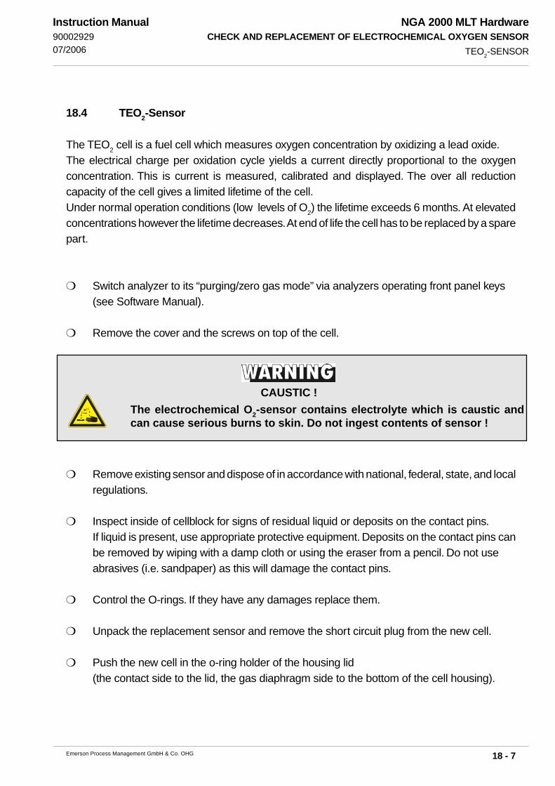
NGA 2000 MLT HardwareCHECK AND REPLACEMENT OF ELECTROCHEMICAL OXYGEN SENSOR
18 - 7Emerson Process Management GmbH & Co. OHG
Instruction Manual9000292907/2006
18.4 TEO2-Sensor
The TEO2 cell is a fuel cell which measures oxygen concentration by oxidizing a lead oxide.
The electrical charge per oxidation cycle yields a current directly proportional to the oxygenconcentration. This is current is measured, calibrated and displayed. The over all reductioncapacity of the cell gives a limited lifetime of the cell.Under normal operation conditions (low levels of O
2) the lifetime exceeds 6 months. At elevated
concentrations however the lifetime decreases. At end of life the cell has to be replaced by a sparepart.
Switch analyzer to its “purging/zero gas mode” via analyzers operating front panel keys(see Software Manual).
Remove the cover and the screws on top of the cell.
Remove existing sensor and dispose of in accordance with national, federal, state, and localregulations.
Inspect inside of cellblock for signs of residual liquid or deposits on the contact pins.If liquid is present, use appropriate protective equipment. Deposits on the contact pins canbe removed by wiping with a damp cloth or using the eraser from a pencil. Do not useabrasives (i.e. sandpaper) as this will damage the contact pins.
Control the O-rings. If they have any damages replace them.
Unpack the replacement sensor and remove the short circuit plug from the new cell.
Push the new cell in the o-ring holder of the housing lid(the contact side to the lid, the gas diaphragm side to the bottom of the cell housing).
TEO2-SENSOR
The electrochemical O2-sensor contains electrolyte which is caustic andcan cause serious burns to skin. Do not ingest contents of sensor !
CAUSTIC !

NGA 2000 MLT HardwareCHECK AND REPLACEMENT OF ELECTROCHEMICAL OXYGEN SENSOR
18 - 8 Emerson Process Management GmbH & Co. OHG
Instruction Manual90002929
07/2006
Place the lid on the housing, fasten the screws and close the cover.
Purge gas paths with inert gas (nitrogen (N2)) or sample gas as soon aspossible to avoid prolonged exposure of the sensor to high concentra-tions of oxygen.The longer the sensor is exposed to air, the longer it will take for the sen-sor to recover to low ppm levels. When installing a new sensor or startingthe instrument for the first time, it may take as long as eight hours for theanalyzer to purge down to the lowest operating range.Prolonged exposure of the sensor to air can cause extended start up time,reduction of performance or damage to the sensor.
Perform adjustment of sensor (chapter 7.)
Notes for analyzers with electrochemical TEO2 cell!For TEO2 sensor please note that the gas inlet and outlet connections of the analyzer are sealedto prevent exposure of the sensor to air.Prolonged exposure of the sensor to air can cause extended start up time, reduction ofperformance or damage to the sensor. Do not remove the sealing caps until all associated samplehandling components are installed and the instrument is fully ready for installation.
After replacement purge gas paths with inert gas (nitrogen (N2)) or sample gas as soon as possibleto avoid prolonged exposure of the sensor to high concentrations of oxygen.The longer the sensor is exposed to air, the longer it will take for the sensor to recover to low ppmlevels. When installing a new sensor or starting the instrument for the first time, it may take as longas eight hours for the analyzer to purge down to the lowest operating range.Prolonged exposure of the sensor to air can cause extended start up time, reduction ofperformance or damage to the sensor.
After initial startup or startup following a prolonged shutdown, the analyzer may require extendedtime to recover to the range of measurement. Commonly, this is caused by the introduction ofambient air into the sample and/or vent lines to the sensor. The presence of higher than normallevels of oxygen at the sensor will cause the sensor electrolyte to become saturated with dissolvedoxygen. When the instrument is placed in operation, the sensor must now consume all excessdissolved oxygen above the desired measuring level.
All analyzers with electrochemical TEO2 cell have to be purged with inert gas (Nitrogen, N2) priorto disconnect the gas lines ! Then the gas line fittings have to be closed for transport or depositinganalyzer.
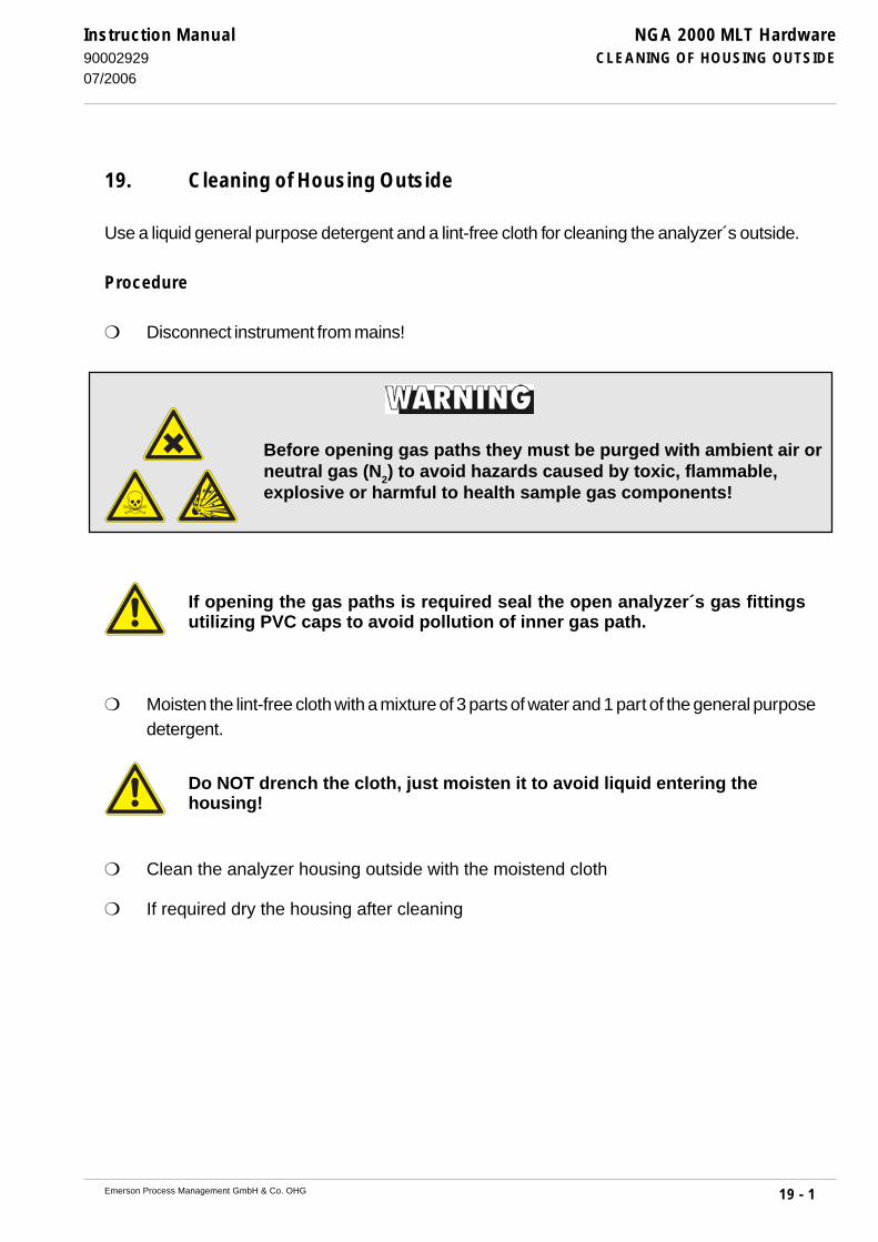
NGA 2000 MLT HardwareCLEANING OF HOUSING OUTSIDE
19 - 1Emerson Process Management GmbH & Co. OHG
Instruction Manual9000292907/2006
19. Cleaning of Housing Outside
Use a liquid general purpose detergent and a lint-free cloth for cleaning the analyzer´s outside.
Procedure
Disconnect instrument from mains!
If opening the gas paths is required seal the open analyzer´s gas fittingsutilizing PVC caps to avoid pollution of inner gas path.
Moisten the lint-free cloth with a mixture of 3 parts of water and 1 part of the general purposedetergent.
Do NOT drench the cloth, just moisten it to avoid liquid entering thehousing!
Clean the analyzer housing outside with the moistend cloth
If required dry the housing after cleaning
Before opening gas paths they must be purged with ambient air orneutral gas (N2) to avoid hazards caused by toxic, flammable,explosive or harmful to health sample gas components!

NGA 2000 MLT HardwareCLEANING OF HOUSING OUTSIDE
19 - 2 Emerson Process Management GmbH & Co. OHG
Instruction Manual90002929
07/2006

NGA 2000 MLT HardwareTECHNICAL DATA
20 - 1Emerson Process Management GmbH & Co. OHG
Instruction Manual9000292901/2007
20. Technical Data
Certifications EN 61326, EN 61010-1(for measurment of not flammable gases or not
explosive gases resp. (< 50 % LEL). NAMUR, CSA-C/US*), C-Tick, PAC, BRMLBigger concentrations requires supplementary GOSST: VNIIMS, Pattern (Belarussia)
protective measures !) *) MLT 2-NF (“Non-Flammable sample only”):USA: Class I, Zone 2, Ex p II T4Canada: AEx p II T4
PCB EXI 01 EC TYPE-EXAMINATION CERTIFICATIONTUEV Nord report No.: 98 ATEX 1341 X
FDA Test: 0-10 ppm CO (MLT1/3) TUEV Nord report No.: 98 CU 012
Suitability tests (MCERTS/TUEV/QAL 1): CO/NO/NO2/SO2/O2 measurement936/806017/A&D (MLT 1/ 2) TI Air, 13th BImSchV936/806017/B&E (MLT 2/ 3 / 4) TI Air, 13th BImSchV, 17th BImSchV- MLT 1 Sira MC 050051/00- MLT 2 Sira MC 050052/01- MLT 3/ MLT 4 Sira MC 050053/01- MLT 1/ MLT 2 QAL 1 (EN 14181, EN ISO 14956)- MLT 2/ MLT 3/ MLT 4 QAL 1 (EN 14181, EN ISO 14956)
20.1 Housing see dimensionsl skteches (Fig. 20-1 to 20-8)Gas connections: Standard 6/4 mm PVDF
- Sample gas Option: 6/4 mm or 1/4", ss- Reference gas MLT 1 max. 8 fittings- Purge gas MLT 2 max. 6 fittings
MLT 3 max. 4 fittingsMLT 4 max. 6 fittings
CAT 200 max. 11 fittings
Weight (depending on configuration)MLT 1 approx. 8 - 13 kgMLT 2 (standard version) approx. 30 - 35 kgMLT 3/4 approx. 13 - 18 kgCAT 200 approx. 55 - 70 kg
HOUSING

NGA 2000 MLT HardwareTECHNICAL DATA
20 - 2 Emerson Process Management GmbH & Co. OHG
Instruction Manual90002929
01/2007
Protection class (according to DIN standard 40050)MLT 1/3/4 IP 20MLT 2 IP 65 (NEMA4/4X)CAT 200 IP 55 (IP 66 w/o breather), optional with
internal tropicalization
Data line & main line glands EEx e II KEMA, cable diameter 7 to 12 mm
Permissible ambient temperature (operation):- MLT 1/ MLT 2/ MLT 3/ MLT 4 + 5 to + 40 °C (45 °C as option, not EO
2)
- CAT 200 0 to 50 °C; -30°C (GP & CSA-C/US only)
Permissible storage temperature - 20 °C to + 70 °C
Humidity (non condensing) < 90 % rel. humidity at + 20 °C< 70 % rel. humidity at + 40 °C
Rain / Drop and splash water The MLT must not be exposed to rain ordrop/splash water
Explosive atmosphere The MLT must not be operated in explosiveatmosphere without supplementaryprotective measures
Ventilation Free flow of air into and out of the MLT(ventilation slits) must not be hindered bynearby objects or walls !
Altitude 0-2000 m (above sea level)
20.2 Options
Pressure sensor Measuring range 800 - 1,100 hPa
Fine dust filter (MLT 3) Filter material PTFE, Pore size approx. 2 μm
Sample gas pump (MLT 3) Pumping rate max. 2.5 l/min.Suction pressure min. 900 hPaFor mobile application of MLT only !Lifetime max. 5,000 running hours !
HOUSING / OPTIONS

NGA 2000 MLT HardwareTECHNICAL DATA
20 - 3Emerson Process Management GmbH & Co. OHG
Instruction Manual9000292901/2007
20.3 General Specifications
Measuring components see order confirmation
Measuring ranges
NDIR/VIS/UV see order confirmation
paramagnetic oxygen sensor (PO2) 0 - 5 % to 0 - 100 % O2 or0 - 2 % to 0 - 25 % O2
0 - 1 % to 0 - 10 % O2 *)
electrochemical oxygen sensor (EO2) 0 - 5 % O2 to 0 - 25 % O2 **)
trace electrochemical oxygen sensor (TEO2) 0 - 100 ppm O2 to 0 - 5,000 ppm O2 ***)
thermal conductivity sensor (TC) 0 - 2 % to 0 - 100 % H2
0 - 1 % H2 *)
0 - 50 % to 0 - 100 % Ar0 - 30 % to 0 - 100 % CO
2
0 - 10 % to 0 - 100 % He
GENERAL SPECIFICATIONS
*) non standard specifications **) higher measuring ranges reduce sensor lifetime***) lower measuring ranges on request (c.f.)

NGA 2000 MLT HardwareTECHNICAL DATA
20 - 4 Emerson Process Management GmbH & Co. OHG
Instruction Manual90002929
01/2007
1) related to full scale2) related to measuring value3) from analyzer gas inlet at gas flow of approx. 1.0 l/min.
(electrical = 2 s)4) constant pressure and temperature5) dependent on integrated photomoter bench / sensor6) paramagnetic oxygen measurement (PO2)7) depending on sensor position
8) optional pressure sensor is required 9) standard 55 °C, optional 65 °C, not for MLT 110) located in thermostated chamber (MLT 2/3/4) /
thermostated sensor (MLT 1/2)11) starting from +20 °C (to +5 °C or to + 40 °C)12) sensor / cell only13) electrochemical oxygen measurement (EO2),
not located in thermostated chamber14) no sudden surge for PO2 allowed!
Specifications of MLT:
Table 20-1 NDIR / VIS / UV Oxygen Sensor Thermal
(PO2 and EO2) Conductivity (TC)
Detection limit ≤ 1 % 1) 4) ≤ 1 % 1) 4) ≤ 2 % 1) 4)
Linearity ≤ 1 % 1) 4) ≤ 1 % 1) 4) ≤ 1 % 1) 4)
Zero-point drift ≤ 2 % per week 1) 4) ≤ 2 % per week 1) 4) ≤ 2 % per week 1) 4)
Span (sensitivity) drift ≤ 0.5 % per week 1) 4) ≤ 1 % per week 1) ≤ 1 % per week 1) 4)
Repeatability ≤ 1 % 1) 4) ≤ 1 % 1) 4) ≤ 1 % 1) 4)
Response time (t90) 3 s ≤ t90
≤ 7 s 3) 5) < 4 s (increasing) 3) 6) 3 s ≤ t90
≤ 20 s 3) 7)
< 5 s (decreasing) 3) 6)
approx. 12 s 3) 13)
Permissible gas flow 0.2 - 1.5 l/min 0.2 - 1.0 l/min 6) 0.2 - 1.0 (+/- 0.1) l/min
0.2 - 1.5 l/min 13)
Influence of gas flow ≤ 2 % 1) 4) ≤ 1 % 1) 4)
Permissible pressure ≤ 1,500 hPa abs. ≤ 1,500 hPa abs. 14) ≤ 1,500 hPa abs.
Influence of pressure
(at constant temperature) ≤ 0.10 % per hPa 2) ≤ 0.10 % per hPa 2) ≤ 0.10 % per hPa 2)
(with pressure compensation) 8) ≤ 0.01 % per hPa 2) ≤ 0.01 % per hPa 2) ≤ 0.01 % per hPa 2)
Influence of temperature
(pressure constant)
- on zero point ≤ 1 % per 10 K 1) ≤ 1 % per 10 K 1) ≤ 1 % per 10 K in 1 h 1)
- on span (sensitivity) ± 5 % (+5 to +40 °C) 1) 11) ≤ 1 % per 10 K 1) ≤ 2 % per 10 K in 1 h 1)
Thermostatting approx. 55 °C 9) approx. 55 °C 6) 10) 13) approx. 75 °C 12)
none 13)
Heating-up time approx. 15 to 50 minutes 5) 15 to 50 minutes 5) approx. 15 to 50 minutes
GENERAL SPECIFICATIONS

NGA 2000 MLT HardwareTECHNICAL DATA
20 - 5Emerson Process Management GmbH & Co. OHG
Instruction Manual9000292901/2007
Altered NDIR/VIS/UV-Specifications of MLT-ULCO compared to table 20-1:
Table 20-2 COultra low 0 - 10 ppm COlow 0 - 50 ... 2,500 ppm
CO2, ultra low 0 - 5 ppm COhigh 0 - 0.5 ... 10 %
CO2 0 - 1 ... 12 % 2)
Detection limit ≤ 0.2 ppm 3) ≤ 1 % 1) 3)
Linearity ≤ ± 1 % of NV 3) (NV ≥ lowest range) ≤ ± 1 % of NV 3) (NV ≥ 10 % of lowest range)
Zero-point drift ≤ ± 0.2 ppm in 24 hr 3) ≤ 2 % per week 1) 3)
Span (sensitivity) drift ≤ ± 0.2 ppm in 24 hr 3) ≤ 0.5 % per week 1) 3)
Repeatability ≤ ± 0.2 ppm 3) ≤ 1 % 1) 3)
Response time (t90) < 7 s 5) 6) (< 4 s 6) 7)) 3 s ≤ t90 ≤ 7 s 6) 7)
Influence of gas flow ≤ ± 2 % 1) 3) ≤ ± 1 % 1) 3)
Influence of temperature
(pressure constant)
- on zero point ≤ ± 5 % (+ 5 °C to + 40 °C) 1) 4) ≤ ± 1 % per 10 K 1)
- on span (sensitivity) ≤ ± 5 % (+ 5 °C to + 40 °C) 1) 4) ≤ ± 5 % (+ 5 °C to + 40 °C) 1) 4)
Thermostatting none none
Cross sensitivitieselectrochemical oxygen measurement Not for use with sample gases containing
FCHC´s !
paramagnetic oxygen measurement 100 % Gas zero-level effect % O2
N2
0,00
CO2
- 0,27
H2
+ 0,24
Ar - 0,22
Ne + 0,13
He + 0,30
CO + 0,01
CH4
- 0,20
C2 H
6- 0,46
C2 H
4- 0,26
C3 H
8- 0,86
C3 H
6- 0,55
NO + 43,0
NO2
+ 28,0
N2O - 0,20
SPECIFICATIONS ULCO
1) related to full scale 2) CO2 0 - 1 ... 15 % on request3) constant pressure and temperature 4) starting from +20 °C (to +5 °C or to + 40 °C)5) from analyzer gas inlet at gas flow of approx. 1.0 l/min. (electrical = 4 s) 6) dependent on integrated photomoter bench7) from analyzer gas inlet at gas flow of approx. 1.0 l/min. (electrical = 2 s) NV = Nominal value

NGA 2000 MLT HardwareTECHNICAL DATA
20 - 6 Emerson Process Management GmbH & Co. OHG
Instruction Manual90002929
07/2006
Fig. 20-1: Dimensional sketch MLT 1 [all dimensions in mm]
Side view
Rear viewFront view (analyzer module with blank plate)
Analyzer / analyzer module for rack mounting / table-top
Analyzer module for platform mounting
Front view(network/24 V dc for platform mounting only)
Rear view(network/24 V dc for outside mounting only)
Side view
DIMENSIONS MLT 1
NETWORK
24 VDC / IN

NGA 2000 MLT HardwareTECHNICAL DATA
20 - 7Emerson Process Management GmbH & Co. OHG
Instruction Manual9000292907/2006
Fig. 20-2: Dimensional sketch / Drill drawing MLT 2 Standard version [all dimensions in mm]
Fig. 20-3: Dimensional sketch / Drill drawing MLT 2 Dual housing version [all dimensions in mm]
DIMENSIONS MLT 2
Gas connections
glands(connection cables)
approx. 355
1818
43
27
603
635
550
492
300 38 3838
280 16
10
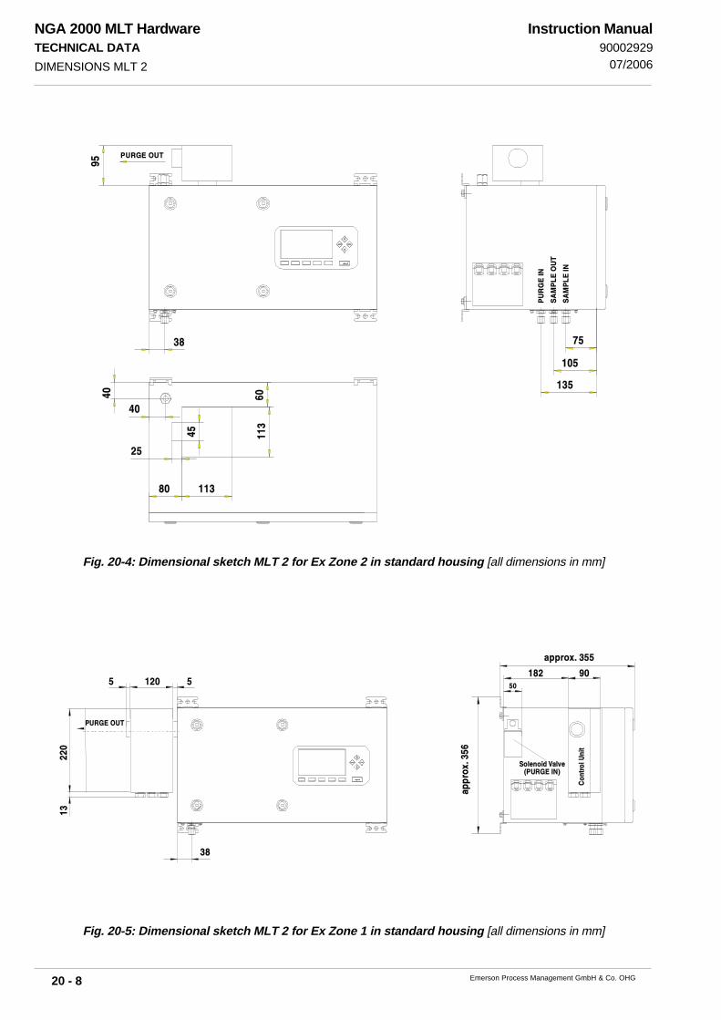
NGA 2000 MLT HardwareTECHNICAL DATA
20 - 8 Emerson Process Management GmbH & Co. OHG
Instruction Manual90002929
07/2006
Fig. 20-4: Dimensional sketch MLT 2 for Ex Zone 2 in standard housing [all dimensions in mm]
DIMENSIONS MLT 2
Fig. 20-5: Dimensional sketch MLT 2 for Ex Zone 1 in standard housing [all dimensions in mm]
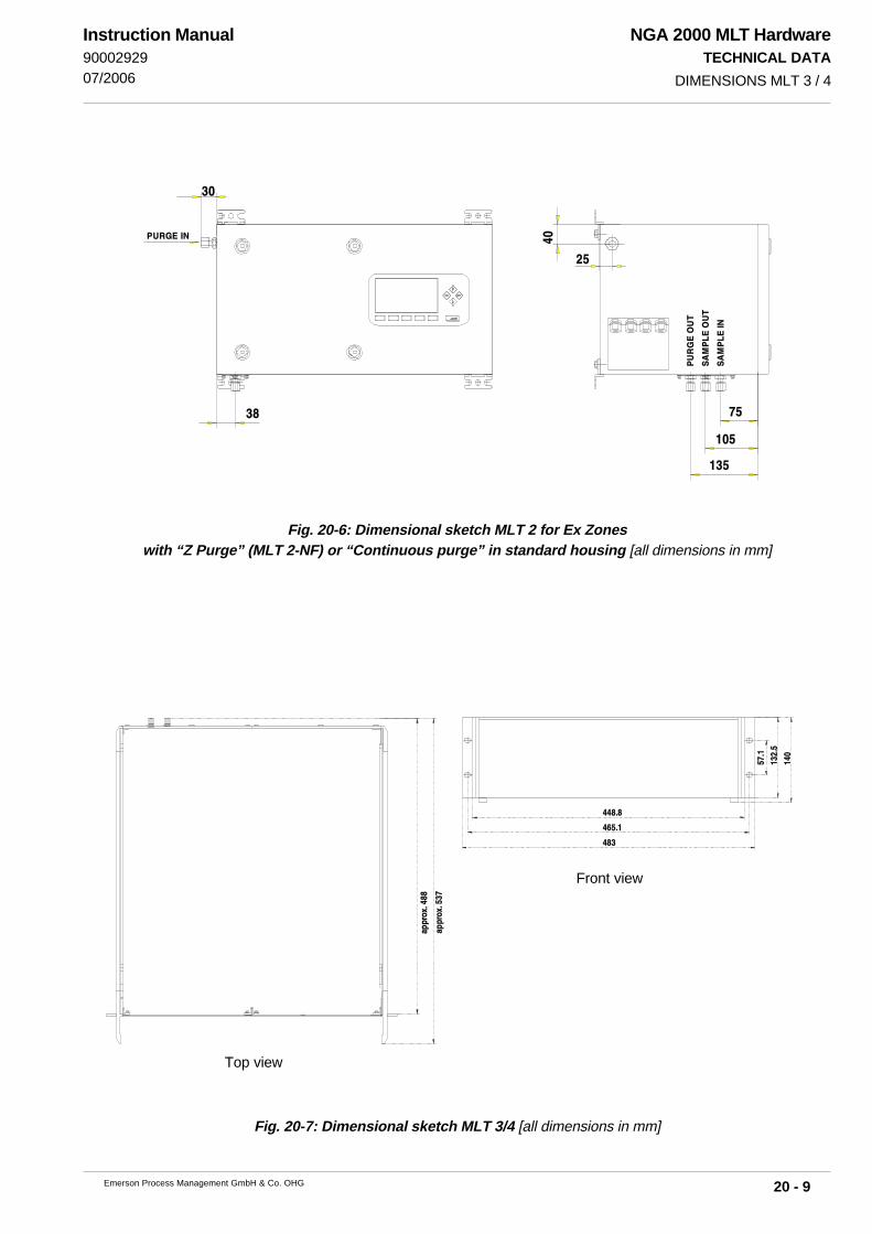
NGA 2000 MLT HardwareTECHNICAL DATA
20 - 9Emerson Process Management GmbH & Co. OHG
Instruction Manual9000292907/2006
Front view
Top view
Fig. 20-7: Dimensional sketch MLT 3/4 [all dimensions in mm]
DIMENSIONS MLT 3 / 4
Fig. 20-6: Dimensional sketch MLT 2 for Ex Zoneswith “Z Purge” (MLT 2-NF) or “Continuous purge” in standard housing [all dimensions in mm]
!
"
!#
$$ %!"
$$ %

NGA 2000 MLT HardwareTECHNICAL DATA
20 - 10 Emerson Process Management GmbH & Co. OHG
Instruction Manual90002929
07/2006
Fig. 20-8: Dimensional sketch / Drill drawing CAT 200 [all dimensions in mm (Inch)]
DIMENSIONS CAT 200
(0.85)
(13)
(25.4)
(0.63
)
(14.
3)
(27)

NGA 2000 MLT HardwareTECHNICAL DATA
20 - 11Emerson Process Management GmbH & Co. OHG
Instruction Manual9000292901/2007
20.4 Voltage supply
20.4.1 Analyzers
20.4.1.1 MLT 1/4Input 3-pole XLR- Flange (male), lockableVoltage Supply 24 V dc (+/- 5 %) / 3 A (MLT 1) / 5 A (MLT 4)[For ac operation 230/120 V dc supply by options SL10, SL5 (both for rack
mounting only) UPS 01 T, or equivalent power supply]
20.4.1.2 MLT 2/3Input terminal strips (MLT 2) / plug (MLT 3)integrated power supply MLT 2: SL5 or SL10
MLT 3 UPSPower Consumption MLT 2 max. 700 VAFuses MLT 2 (internal) T 6.3A/250 V (2 pcs.)
20.4.1.3 CAT 200Connection via screw terminal blocks injunction box, cross section: 4 mm2 max.Rated input voltage 115-230 V 50/60 HzInput voltage range 90 - 264 V , 47 - 63 HzRated input power max. 380 W
20.4.1.4 Electrical Safety
Over-voltage category II
Pollution degree 2Safety Class 2 for MLT 1/4 instruments.
1 for MLT 2/3 instrumentsall I/O´s SELV voltage
optically isolated to electrical supply
VOLTAGE SUPPLY: ANALYZERS
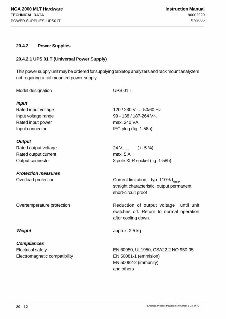
NGA 2000 MLT HardwareTECHNICAL DATA
20 - 12 Emerson Process Management GmbH & Co. OHG
Instruction Manual90002929
07/2006POWER SUPPLIES: UPS01T
20.4.2 Power Supplies
20.4.2.1 UPS 01 T (Universal Power Supply)
This power supply unit may be ordered for supplying tabletop analyzers and rack mount analyzersnot requiring a rail mounted power supply.
Model designation UPS 01 T
InputRated input voltage 120 / 230 V 50/60 HzInput voltage range 99 - 138 / 187-264 VRated input power max. 240 VAInput connector IEC plug (fig. 1-58a)
OutputRated output voltage 24 V (+- 5 %)Rated output current max. 5 AOutput connector 3 pole XLR socket (fig. 1-58b)
Protection measuresOverload protection Current limitation, typ. 110% Irated,
straight characteristic, output permanentshort-circuit proof
Overtemperature protection Reduction of output voltage until unitswitches off. Return to normal operationafter cooling down.
Weight approx. 2.5 kg
CompliancesElectrical safety EN 60950, UL1950, CSA22.2 NO 950-95Electromagnetic compatibility EN 50081-1 (emmision)
EN 50082-2 (immunity)and others
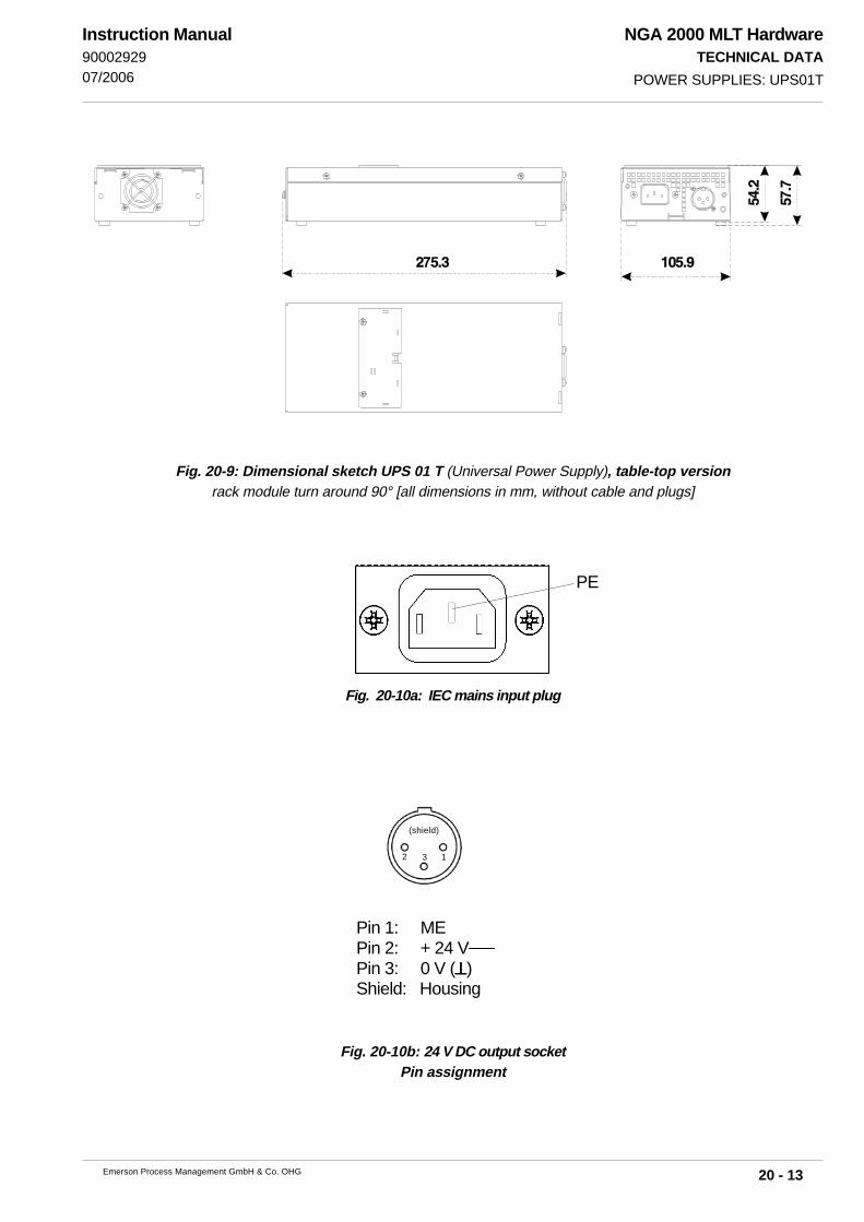
NGA 2000 MLT HardwareTECHNICAL DATA
20 - 13Emerson Process Management GmbH & Co. OHG
Instruction Manual9000292907/2006 POWER SUPPLIES: UPS01T
Fig. 20-9: Dimensional sketch UPS 01 T (Universal Power Supply), table-top versionrack module turn around 90° [all dimensions in mm, without cable and plugs]
Fig. 20-10b: 24 V DC output socketPin assignment
Fig. 20-10a: IEC mains input plug
PE
Pin 1: MEPin 2: + 24 VPin 3: 0 V (⊥⊥⊥⊥⊥)Shield: Housing
2 13
(shield)
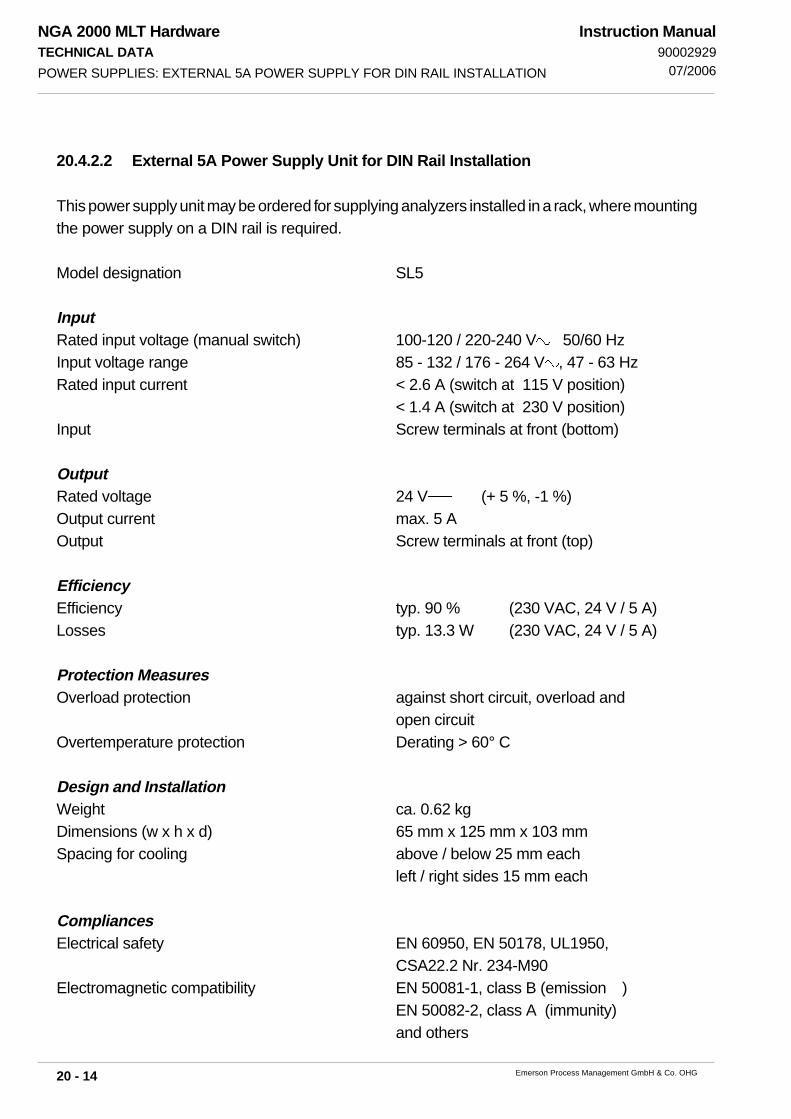
NGA 2000 MLT HardwareTECHNICAL DATA
20 - 14 Emerson Process Management GmbH & Co. OHG
Instruction Manual90002929
07/2006
20.4.2.2 External 5A Power Supply Unit for DIN Rail Installation
This power supply unit may be ordered for supplying analyzers installed in a rack, where mountingthe power supply on a DIN rail is required.
Model designation SL5
InputRated input voltage (manual switch) 100-120 / 220-240 V 50/60 HzInput voltage range 85 - 132 / 176 - 264 V , 47 - 63 HzRated input current < 2.6 A (switch at 115 V position)
< 1.4 A (switch at 230 V position)Input Screw terminals at front (bottom)
OutputRated voltage 24 V (+ 5 %, -1 %)Output current max. 5 AOutput Screw terminals at front (top)
EfficiencyEfficiency typ. 90 % (230 VAC, 24 V / 5 A)Losses typ. 13.3 W (230 VAC, 24 V / 5 A)
Protection MeasuresOverload protection against short circuit, overload and
open circuitOvertemperature protection Derating > 60° C
Design and InstallationWeight ca. 0.62 kgDimensions (w x h x d) 65 mm x 125 mm x 103 mmSpacing for cooling above / below 25 mm each
left / right sides 15 mm each
CompliancesElectrical safety EN 60950, EN 50178, UL1950,
CSA22.2 Nr. 234-M90Electromagnetic compatibility EN 50081-1, class B (emission )
EN 50082-2, class A (immunity)and others
POWER SUPPLIES: EXTERNAL 5A POWER SUPPLY FOR DIN RAIL INSTALLATION

NGA 2000 MLT HardwareTECHNICAL DATA
20 - 15Emerson Process Management GmbH & Co. OHG
Instruction Manual9000292907/2006 POWER SUPPLIES: EXTERNAL 5A POWER SUPPLY FOR DIN RAIL INSTALLATION
Fig. 20-11: Power Supply SL5Dimensions (approx. [mm])
Right side Front side Bottom side

NGA 2000 MLT HardwareTECHNICAL DATA
20 - 16 Emerson Process Management GmbH & Co. OHG
Instruction Manual90002929
07/2006
20.4.2.3 External 10A Power Supply Unit for DIN Rail Installation
This power supply unit may be ordered for supplying analyzers installed in a rack, where mountingthe power supply on a DIN rail is required.
Model designation SL10
InputRated input voltage (manual switch) 100-120 / 220-240 V 50/60 HzInput voltage range 85 - 132 / 176 - 264 V , 47 - 63 HzRated input current < 6 A (switch at 115 V position)
< 2.8 A (switch at 230V position)Input Screw terminals at front (left side)
OutputRated voltage 24 V (+ 5 %, -1 %)Output current max. 10 AOutput Screw terminals at front (right side)
EfficiencyEfficiency typ. 89 % (230 VAC, 24 V / 10 A)Losses typ. 29 W (230 VAC, 24 V / 10 A)
Protection MeasuresOverload protection against short circuit, overload and
open circuitOvertemperature protection Derating > 60° C
Design and InstallationWeight approx. 1.2 kgDimensions (w x h x d) 120 mm x 124 mm x 102 mmSpacing for cooling above / below 25 mm each
left / right sides 15 mm each
CompliancesElectrical safety EN 60950, EN 50178, UL1950,
CSA22.2 Nr. 234-M90Electromagnetic compatibility EN 50081-1, class B (emission)
EN 50082-2, class A (immunity)and others
POWER SUPPLIES: EXTERNAL 10A POWER SUPPLY FOR DIN RAIL INSTALLATION

NGA 2000 MLT HardwareTECHNICAL DATA
20 - 17Emerson Process Management GmbH & Co. OHG
Instruction Manual9000292907/2006
Fig. 20-12:Power Supply SL 10Dimensions (approx. [mm])
POWER SUPPLIES: EXTERNAL 10A POWER SUPPLY FOR DIN RAIL INSTALLATION
Right side Front side Bottom side

NGA 2000 MLT HardwareTECHNICAL DATA
20 - 18 Emerson Process Management GmbH & Co. OHG
Instruction Manual90002929
07/2006
20.4.2.4 Tabletop Power Supply Units
This power supply unit may be ordered for supplying two tabletop analyzers by one sharedpower supply unit.A variation for installation in a module rack is available, too, with output currents of 10 A or5 A.
Model designations 10 A tabletop power supply unit10 A rack module power supply unit5 A rack module power supply unit
For electrical input and output data, efficiency, protection measures and compliances (internalpower supply unit only) see
section 20.4.2.3 for 10 A versionssection 20.4.2.2 for 5 A version.
Design and InstallationDimensions, approx. (w x h x d) 142 mm x 260 mm x 128 mmSpacing for cooling front / rear side 15 mm each
Fig. 20-13: 10 A Tabletop Power SupplyDimensions (approx. [mm])
POWER SUPPLIES: TABLETOP POWER SUPPLY UNITS
Front side
Interior view (cover removed)
Rear side

NGA 2000 MLT HardwarePIN ASSIGNMENTS
21 - 1Emerson Process Management GmbH & Co. OHG
Instruction Manual9000292907/2006
21. Pin Assignments
To stay in compliance with regulations regarding electromagnetic compat-ibility it is recommended to use only shielded cables, as optionally avail-able from Emerson Process Management or equivalent. Customer has totake care that the shield is connected in proper way. Shield and signal con-nector enclosure need to be conductively connected, submin-d plugs andsockets must be screwed to the analyzer.
Using external submin-d-to-terminal adaptor elements (option) affects elec-tromagnetic compatibility. In this case the customer has to take measuresto stayin compliance and has to declare conformity, when required by leg-islation (e.g. European EMC Directive).Adaptor terminals are one-to-one connected to the submin-d pin of samedesignation: Terminal 1 is connected to pin 1, terminal 2 to pin 2 etc. !
21.1 24 V dc Input (MLT 1/4)
21.2 230/120 V ac Input (MLT 3)
Fig. 21-1: Pin assignments 24 V dc Input (MLT 1/4)
Fig. 21-2: Pin assignments 230/120 V ac Input (MLT 3)
VOLTAGE INPUT
PE
Pin 1: MEPin 2: + 24 V dcPin 3: 0 V DC (⊥⊥⊥⊥⊥)shield: housing flange
213
(shield)
Supplyfrom rear
1
3
2
Supply from front(see Fig. 6-1, too)

NGA 2000 MLT HardwarePIN ASSIGNMENTS
21 - 2 Emerson Process Management GmbH & Co. OHG
Instruction Manual90002929
07/2006
21.3 Option SIO (Standard I/O)
21.3.1 Analog Signal Outputs
1 ± 11 V DC (burden > 2 kΩ), Output 12 ± 22 mA, (burden 500 Ω), Output 13 ± 11 V DC (burden > 2 kΩ), Output 24 ± 22 mA, (burden 500 Ω), Output 25 ⊥⊥⊥⊥⊥ (V DC), Outputs 1 + 26 ⊥⊥⊥⊥⊥ (mA), Outputs 1 + 27 ± 11 V DC (burden > 2 kΩ), Output 3 (Option)8 ± 22 mA, (burden 500 Ω), Output 3 (Option)9 ± 11 V DC (burden > 2 kΩ), Output 4 (Option)10 ± 22 mA, (burden 500 Ω), Output 4 (Option)11 ⊥⊥⊥⊥⊥ (V DC), Outputs 3 + 4 (Option)12 ⊥⊥⊥⊥⊥ (mA), Outputs 3 + 4 (Option)13 FE14 ± 11 V DC (burden > 2 kΩ), Output 5 (Option)15 ± 22 mA, (burden 500 Ω), Output 5 (Option)16 ± 11 V DC (burden > 2 kΩ), Output 6 (Option)17 ± 22 mA, (burden 500 Ω), Output 6 (Option)18 ⊥⊥⊥⊥⊥ (V DC), Outputs 5 + 6 (Option)19 ⊥⊥⊥⊥⊥ (mA), Outputs 5 + 6 (Option)20 ± 11 V DC (burden > 2 kΩ), Output 7 (Option)21 ± 22 mA, (burden 500 Ω), Output 7 (Option)22 ± 11 V DC (burden > 2 kΩ), Output 8 (Option)23 ± 22 mA, (burden 500 Ω), Output 8 (Option)24 ⊥⊥⊥⊥⊥ (V DC), Outputs 7 + 8 (Option)25 ⊥⊥⊥⊥⊥ (mA), Outputs 7 + 8 (Option)
21.3.2 Relay Outputs / Serial Interfaces
1 ⊥⊥⊥⊥⊥ (GND)2 RxD3 TxD4 not used5 ⊥⊥⊥⊥⊥ (GND)6 Relay Contact 1 (max. 30 V / 1 A / 30 W)7 Relay Contact 2 (max. 30 V / 1 A / 30 W)8 Relay Contact 3 (max. 30 V / 1 A / 30 W)9 Relay Contacts (Common)
Fig. 21-3: Pin assignments Socket Analog Signal Outputs (Option SIO)
Fig. 21-4a: Pin assignments Socket Relay Outputs / RS 232 Serial Interface (Option SIO)
1 ⊥⊥⊥⊥⊥ (GND)2 RxD-3 RxD+4 TxD+5 TxD-6 Relay Contact 1 (max. 30 V / 1 A / 30 W)7 Relay Contact 2 (max. 30 V / 1 A / 30 W)8 Relay Contact 3 (max. 30 V / 1 A / 30 W)9 Relay Contacts (Common)
Fig. 21-4b: Pin assignments Socket Relay Outputs / RS 485 Serial Interface (Option SIO)
OPTION SIO
14
25
1
13
6
9
1
5
6
9
1
5
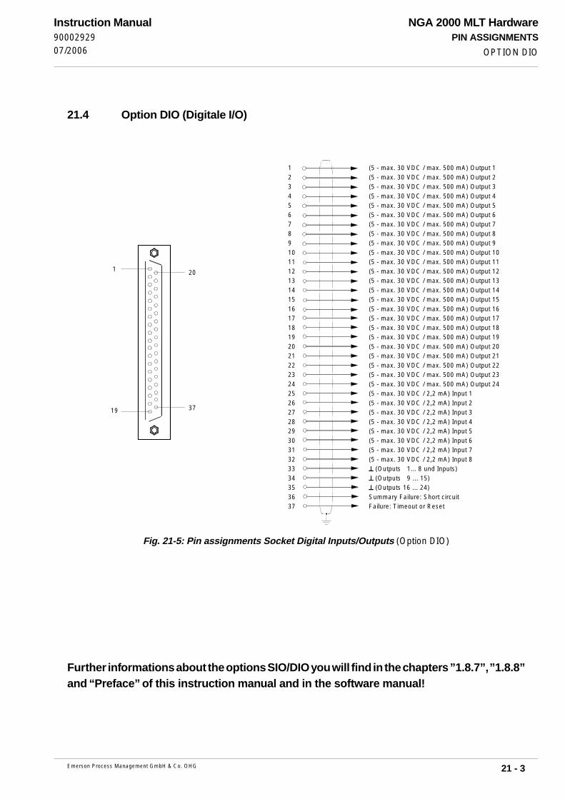
NGA 2000 MLT HardwarePIN ASSIGNMENTS
21 - 3Emerson Process Management GmbH & Co. OHG
Instruction Manual9000292907/2006
21.4 Option DIO (Digitale I/O)
1 (5 - max. 30 VDC / max. 500 mA) Output 12 (5 - max. 30 VDC / max. 500 mA) Output 23 (5 - max. 30 VDC / max. 500 mA) Output 34 (5 - max. 30 VDC / max. 500 mA) Output 45 (5 - max. 30 VDC / max. 500 mA) Output 56 (5 - max. 30 VDC / max. 500 mA) Output 67 (5 - max. 30 VDC / max. 500 mA) Output 78 (5 - max. 30 VDC / max. 500 mA) Output 89 (5 - max. 30 VDC / max. 500 mA) Output 910 (5 - max. 30 VDC / max. 500 mA) Output 1011 (5 - max. 30 VDC / max. 500 mA) Output 1112 (5 - max. 30 VDC / max. 500 mA) Output 1213 (5 - max. 30 VDC / max. 500 mA) Output 1314 (5 - max. 30 VDC / max. 500 mA) Output 1415 (5 - max. 30 VDC / max. 500 mA) Output 1516 (5 - max. 30 VDC / max. 500 mA) Output 1617 (5 - max. 30 VDC / max. 500 mA) Output 1718 (5 - max. 30 VDC / max. 500 mA) Output 1819 (5 - max. 30 VDC / max. 500 mA) Output 1920 (5 - max. 30 VDC / max. 500 mA) Output 2021 (5 - max. 30 VDC / max. 500 mA) Output 2122 (5 - max. 30 VDC / max. 500 mA) Output 2223 (5 - max. 30 VDC / max. 500 mA) Output 2324 (5 - max. 30 VDC / max. 500 mA) Output 2425 (5 - max. 30 VDC / 2,2 mA) Input 126 (5 - max. 30 VDC / 2,2 mA) Input 227 (5 - max. 30 VDC / 2,2 mA) Input 328 (5 - max. 30 VDC / 2,2 mA) Input 429 (5 - max. 30 VDC / 2,2 mA) Input 530 (5 - max. 30 VDC / 2,2 mA) Input 631 (5 - max. 30 VDC / 2,2 mA) Input 732 (5 - max. 30 VDC / 2,2 mA) Input 833 ⊥⊥⊥⊥⊥ (Outputs 1... 8 und Inputs)34 ⊥⊥⊥⊥⊥ (Outputs 9 ... 15)35 ⊥⊥⊥⊥⊥ (Outputs 16 ... 24)36 Summary Failure: Short circuit37 Failure: Timeout or Reset
Fig. 21-5: Pin assignments Socket Digital Inputs/Outputs (Option DIO)
OPTION DIO
Further informations about the options SIO/DIO you will find in the chapters ”1.8.7”, ”1.8.8”and “Preface” of this instruction manual and in the software manual!
201
3719

NGA 2000 MLT HardwarePIN ASSIGNMENTS
21 - 4 Emerson Process Management GmbH & Co. OHG
Instruction Manual90002929
07/2006
21.5 Terminal Assignment of CAT 200
CAT 200
Fig. 21-6: CAT 200, Junction box, interior view
1 Cable gland mains2 Mains terminals3 Upper signal terminals (24)
4 Lower signal terminals (24).5 Signal cable glands (max. 3)
1 2 4 3 5
1 24
241
1 5
Note!Assignment of signals to signal terminals inside junction box varies depending on selected analyzeroptions. For assignments of your specific analyzer refer to the label on the inner side of the junctionbox cover.
General terminal assignments (examples) for the different kinds of available signals are given on thefollowing pages.

NGA 2000 MLT HardwarePIN ASSIGNMENTS
21 - 5Emerson Process Management GmbH & Co. OHG
Instruction Manual9000292907/2006
Table 21-1: CAT 200 Power Connections Terminal Assignments
Table 21-2: CAT 200 Analog Signal Outputs Terminal Assignments (Option SIO)
Table 21-3: CAT 200 Relay Outputs Terminal Assignments (Option SIO)
CAT 200
Table 21-4: CAT 200 Field Bus Terminal Assignments (Option)
Terminal DescriptionLower 10 Field Bus +
Lower 11 Field Bus -
Lower 12 Ground Field Bus
Terminal DescriptionLower 6 Relay Contact 1 (max. 30 V / 1 A / 30 W)
Lower 7 Relay Contact 2 (max. 30 V / 1 A / 30 W)
Lower 8 Relay Contact 3 (max. 30 V / 1 A / 30 W)
Lower 9 Relay Contacts Cmmon
Terminal DescriptionUpper 1 ± 22 mA, (burden 500 Ω), Output 1
Upper 2 ± 22 mA, (burden 500 Ω), Output 2
Upper 3 ⊥ (mA), Outputs 1 + 2
Upper 4 ± 22 mA, (burden 500 Ω), Output 3 (option)
Upper 5 ± 22 mA, (burden 500 Ω), Output 4 (option)
Upper 6 ⊥ (mA), Outputs 3 + 4
Upper 7 ± 22 mA, (burden 500 Ω), Output 5 (option)
Upper 8 ± 22 mA, (burden 500 Ω), Output 6 (option)
Upper 9 ⊥ (mA), Outputs 5 + 6
Upper 10 ± 22 mA, (burden 500 Ω), Output 7 (option)
Upper 11 ± 22 mA, (burden 500 Ω), Output 8 (option)
Upper 12 ⊥ (mA), Outputs 7 + 8
Mains Terminal Description1 Hot (line In)
2 Neutral
3 Ground
4 Ground
5 Ground

NGA 2000 MLT HardwarePIN ASSIGNMENTS
21 - 6 Emerson Process Management GmbH & Co. OHG
Instruction Manual90002929
07/2006
Table 21-5: CAT 200 RS 232 / RS 485 Serial Interface Terminal Assignments (Option SIO)
Table 21-6: CAT 200 Digital Inputs/Outputs Terminal Assignments (Option DIO)
CAT 200
Terminal RS 232 RS 485
Lower 1 Ground Ground
Lower 2 RxD RxD -
Lower 3 TxD RxD +
Lower 4 Not used TxD +
Lower 5 Ground TxD -
Terminal Description
Upper 13 (5 - max. 30 VDC / max. 500 mA) Output 1
Upper 14 (5 - max. 30 VDC / max. 500 mA) Output 2
Upper 15 (5 - max. 30 VDC / max. 500 mA) Output 3
Upper 16 (5 - max. 30 VDC / max. 500 mA) Output 4
Upper 17 (5 - max. 30 VDC / max. 500 mA) Output 5
Upper 18 (5 - max. 30 VDC / max. 500 mA) Output 6
Upper 19 (5 - max. 30 VDC / max. 500 mA) Output 7
Upper 20 (5 - max. 30 VDC / max. 500 mA) Output 8
Upper 21 (5 - max. 30 VDC / max. 500 mA) Output 9
Upper 22 (5 - max. 30 VDC / max. 500 mA) Output 10
Upper 23 (5 - max. 30 VDC / max. 500 mA) Output 11
Upper 24 (5 - max. 30 VDC / max. 500 mA) Output 12
Lower 13 (5 - max. 30 VDC / max. 500 mA) Output 13
Lower 14 (5 - max. 30 VDC / max. 500 mA) Output 14
Lower 15 (5 - max. 30 VDC / max. 500 mA) Output 15
Lower 16 (5 - max. 30 VDC / 2,2 mA) Input 1
Lower 17 (5 - max. 30 VDC / 2,2 mA) Input 2
Lower 18 (5 - max. 30 VDC / 2,2 mA) Input 3
Lower 19 (5 - max. 30 VDC / 2,2 mA) Input 4
Lower 20 (5 - max. 30 VDC / 2,2 mA) Input 5
Lower 21 (5 - max. 30 VDC / 2,2 mA) Input 6
Lower 22 ⊥ (Outputs 1... 8 und Inputs)
Lower 23 ⊥ (Outputs 9...15)

NGA 2000 MLT HardwarePIN ASSIGNMENTS
21 - 7Emerson Process Management GmbH & Co. OHG
Instruction Manual9000292907/2006
21.6 CAT 200 Increased Safety Box - Label Schematic

NGA 2000 MLT HardwarePIN ASSIGNMENTS
21 - 8 Emerson Process Management GmbH & Co. OHG
Instruction Manual90002929
07/2006
Table 21-7: CAT 200 Terminal Assignments - Bottom (Lower) Contacts
Table 21-8: CAT 200 Terminal Assignments - Top (Upper) Contacts
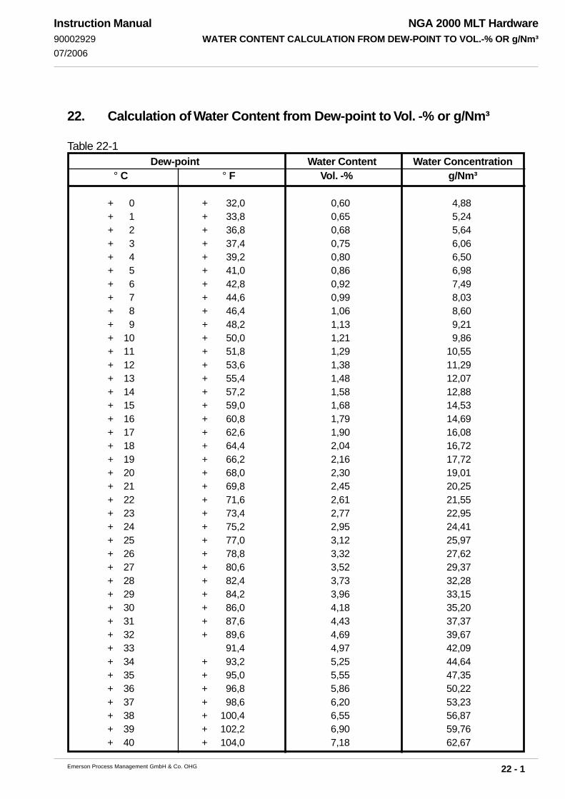
22 - 1
NGA 2000 MLT HardwareWATER CONTENT CALCULATION FROM DEW-POINT TO VOL.-% OR g/Nm³
Emerson Process Management GmbH & Co. OHG
Instruction Manual90002929
07/2006
22. Calculation of Water Content from Dew-point to Vol. -% or g/Nm³
Table 22-1Dew-point Water Content Water Concentration
° C ° F Vol. -% g/Nm³
+ 0 + 32,0 0,60 4,88+ 1 + 33,8 0,65 5,24+ 2 + 36,8 0,68 5,64+ 3 + 37,4 0,75 6,06+ 4 + 39,2 0,80 6,50+ 5 + 41,0 0,86 6,98+ 6 + 42,8 0,92 7,49+ 7 + 44,6 0,99 8,03+ 8 + 46,4 1,06 8,60+ 9 + 48,2 1,13 9,21+ 10 + 50,0 1,21 9,86+ 11 + 51,8 1,29 10,55+ 12 + 53,6 1,38 11,29+ 13 + 55,4 1,48 12,07+ 14 + 57,2 1,58 12,88+ 15 + 59,0 1,68 14,53+ 16 + 60,8 1,79 14,69+ 17 + 62,6 1,90 16,08+ 18 + 64,4 2,04 16,72+ 19 + 66,2 2,16 17,72+ 20 + 68,0 2,30 19,01+ 21 + 69,8 2,45 20,25+ 22 + 71,6 2,61 21,55+ 23 + 73,4 2,77 22,95+ 24 + 75,2 2,95 24,41+ 25 + 77,0 3,12 25,97+ 26 + 78,8 3,32 27,62+ 27 + 80,6 3,52 29,37+ 28 + 82,4 3,73 32,28+ 29 + 84,2 3,96 33,15+ 30 + 86,0 4,18 35,20+ 31 + 87,6 4,43 37,37+ 32 + 89,6 4,69 39,67+ 33 91,4 4,97 42,09+ 34 + 93,2 5,25 44,64+ 35 + 95,0 5,55 47,35+ 36 + 96,8 5,86 50,22+ 37 + 98,6 6,20 53,23+ 38 + 100,4 6,55 56,87+ 39 + 102,2 6,90 59,76+ 40 + 104,0 7,18 62,67

22 - 2
NGA 2000 MLT HardwareWATER CONTENT CALCULATION FROM DEW-POINT TO VOL.-% OR g/Nm³
Emerson Process Management GmbH & Co. OHG
Instruction Manual90002929
07/2006
Dew-point Water Content Water Concentration° C ° F Vol. -% g/Nm³
+ 42 + 107,6 8,10 70,95+ 44 + 111,2 8,99 79,50+ 45 + 113,0 9,45 84,02+ 46 + 114,8 9,96 89,20+ 48 + 118,4 11,07 99,80+ 50 + 122,0 12,04 110,81+ 52 + 125,6 13,43 124,61+ 54 + 129,2 14,80 139,55+ 55 + 131,0 15,55 147,97+ 56 + 132,8 16,29 156,26+ 58 + 136,4 17,91 175,15+ 60 + 140,0 19,65 196,45+ 62 + 143,6 21,55 220,60+ 64 + 147,2 23,59 247,90+ 66 + 150,8 25,80 279,20+ 68 + 154,4 28,18 315,10+ 70 + 158,0 30,75 356,70+ 72 + 161,6 33,50 404,50+ 74 + 165,2 36,47 461,05+ 76 + 168,8 39,66 527,60+ 78 + 172,4 43,06 607,50+ 80 + 176,0 46,72 704,20+ 82 + 179,6 50,65 824,00+ 84 + 183,2 54,84 975,40+ 86 + 186,8 59,33 1171,50+ 88 + 190,4 64,09 1433,30+ 90 + 194,0 69,18 1805,00
Remark: Norm conditions are related to 273 K (0 °C) and 1013 hPa (mbar).
The water concentration is calculated under dry norm conditions which means after
(fictive) subtraction of moisture content on water vapor.

NGA 2000 MLT HardwareInstruction Manual
9000292904/2008
APPENDIX Declaration of Conformity
A-1 MLT 1
A-2 MLT 2
A-3 MLT 3
A-4 MLT 4
A-5 MLT 5


Instruction Manual9000292904/2008 NGA 2000 MLT Hardware

NGA 2000 MLT HardwareInstruction Manual
9000292904/2008
© Emerson Process Management GmbH & Co. OHG 2007
WORLD HEADQUARTERSROSEMOUNT ANALYTICAL EUROPEEmerson Process ManagementGmbH & Co. OHGIndustriestrasse 163594 HasselrothGermanyT 49 6055 884 0F 49 6055 884209
Emerson Process ManagementRosemount Analytical Inc.6565 P Davis Industrial ParkwaySolon, OH 44139 USAT 440.914.1261Toll Free in US and Canada 800.433.6076F 440.914.1271e-mail: [email protected]
www.raihome.com
GAS CHROMATOGRAPHY CENTERAND LATIN AMERICAEmerson Process ManagementRosemount Analytical Inc.11100 Brittmoore Park Drive
Houston, TX 77041
T 713 467 6000
F 713 827 3329
EUROPE, MIDDLE EAST AND AFRICAEmerson Process ManagementShared Services LimitedHeath PlaceBognor RegisWest Sussex PO22 9SHEnglandT 44 1243 863121F 44 1243 845354
ASIA-PACIFICEmerson Process ManagementAsia Pacific Private Limited1 Pandan CrescentSingapore 128461Republic of SingaporeT 65 6 777 8211F 65 6 777 0947e-mail: [email protected]