MantaRay User's Manual - Streamline...
24
Streamline Measurement Ltd MantaRay User's Manual
Transcript of MantaRay User's Manual - Streamline...

Streamline Measurement Ltd
Streamline Measurement Ltd, 01457-864334, [email protected], www.streamlinemeasurement.co.uk
Streamline Measurement Ltd. 11 Hawthorn Bank Hadfield Glossop SK13 2EY
Streamline Measurement Ltd
MantaRay User's Manual

Note: This page has been left blank intentionally.

Page 3
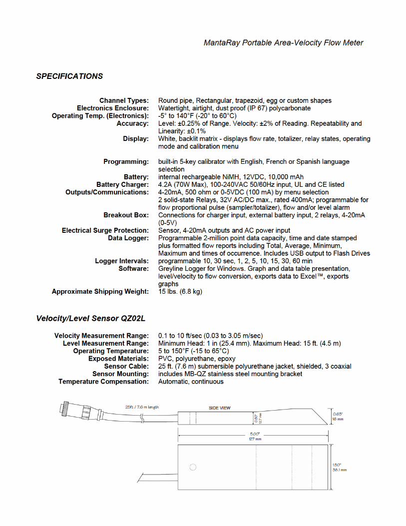
MantaRay Portable Area-Velocity Flow Meter
INDEX
CONNECTIONS ................................................................................................ 4
KEYPAD SYSTEM ............................................................................................ 5
BATTERY .......................................................................................................... 5
CALIBRATION MENU ..................................................................................... 6
ICONS ................................................................................................................. 6
MESSAGE ICON ............................................................................................... 8
STATUS ............................................................................................................. 8
PASSWORD ....................................................................................................... 9
UNITS/MODE .................................................................................................. 10
CALIBRATION................................................................................................ 11
RELAY PARAMETERS .................................................................................. 14
DATA LOGGING ............................................................................................ 15
SPECIAL FUNCTIONS ................................................................................... 17
INSTALLATION - SENSOR LOCATION ...................................................... 19
APPLICATIONS HOTLINE ............................................................................ 22
PRODUCT RETURN PROCEDURE ............................................................... 23
AREA-VELOCITY FLOW DATA SHEET ..................................................... 24
SPECIFICATIONS ........................................................................................... 28
IMPORTANT NOTE: This instrument is manufactured and calibrated to meet product specifications. Please read this manual carefully before installation and operation. Any unauthorized repairs or modifications may result in a suspension of the warranty.
Available in Adobe Acrobat pdf format


Page 9
MantaRay Portable Area-Velocity Flow Meter
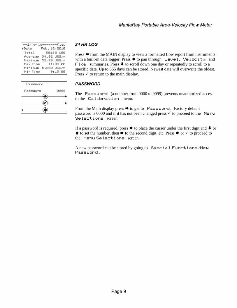
24 HR LOG Press from the MAIN display to view a formatted flow report from instruments with a built-in data logger. Press to pan through Level, Velocity and Flow summaries. Press to scroll down one day or repeatedly to scroll to a specific date. Up to 365 days can be stored. Newest date will overwrite the oldest. Press to return to the main display.
PASSWORD The Password (a number from 0000 to 9999) prevents unauthorized access to the Calibration menu. From the Main display press to get to Password. Factory default password is 0000 and if it has not been changed press to proceed to the Menu
Selections screen. If a password is required, press to place the cursor under the first digit and or to set the number, then to the second digit, etc. Press or to proceed to the Menu Selections screen. A new password can be stored by going to Special Functions/New Password.
--24 hr log------Flow
Date Feb. 12/2010
Total 50138 USG
Average 34.82 USG/m
Maximum 52.20 USG/m
Max Time 11:08:00
Minimum 0.000 USG/m
Min Time 9:15:00
�
--Password----------
Password 0000

Page 10
MantaRay Portable Area-Velocity Flow Meter
UNITS/MODE From Mode press the and then the or to select Flow, Velocity or Level. Flow mode displays the flow rate in engineering units (e.g. gpm, litres/sec, etc.) Press the to store your selection then the to the next menu item. From Linear press the key and then the or to select your units of measurement. Press the to store your selection. Press the key to move the symbol to each subsequent menu item and the to save your selections. Note: the volume selection "bbl" denotes U.S. barrels. Temperature press then to select C or F. Press or to return to the Menu Selections screen.
--Units/Mode--------
Mode Flow
Linear in
Volume USG
Time min
Temperature C
�
--Units/Mode--------
Mode Flow
Linear� in
ftm
mm
--Units/Mode--------
Mode
Linear
�Volume USG
ft3bbl
Lm3
IMGIG
USMG
--Units/Mode--------
Mode Flow
Linear in
Volume USG
Time� sec
day
hr
min
--Units/Mode--------
Mode Flow
Linear in
Volume USG
Time min
Temperature� C
F

Page 12
MantaRay Portable Area-Velocity Flow Meter
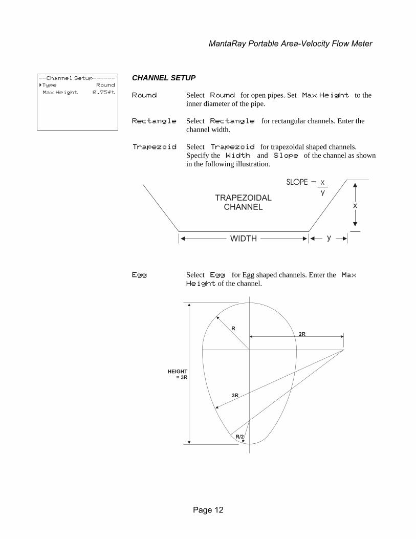
CHANNEL SETUP Round Select Round for open pipes. Set Max Height to the
inner diameter of the pipe. Rectangle Select Rectangle for rectangular channels. Enter the
channel width. Trapezoid Select Trapezoid for trapezoidal shaped channels.
Specify the Width and Slope of the channel as shown in the following illustration.
Egg Select Egg for Egg shaped channels. Enter the Max
Height of the channel.
--Channel Setup------
Type Round
Max Height 0.75ft
�
R
3R
R/2
2R
HEIGHT= 3R
TRAPEZOIDALCHANNEL
yWIDTH
x
SLOPE = x
y

Page 13
MantaRay Portable Area-Velocity Flow Meter
CUSTOM CHANNELS Reset Data Old data MUST be removed before entering data for a new
channel. Press then press to Yes and press to clear old data.
Max Height Enter the maximum height of the channel. Division Divide the maximum height into equal increments (maximum
of 40) and enter this division value (example 1”, 1 cm etc.) Increment # Enter the increment number if you want to edit a previous
entry or to skip entering widths for some levels (Note: The custom channel will interpolate widths between entry points).
Width Enter the measured width of the channel at the level shown
(Note: To enter 0 width you must press and then to store a 0 width data point).
Level Displays the level of the channel for each increment and width
entry.
Note: Custom channel data in equal width increments with variable height measurements must be converted to the format shown above using the “Channel Data Translator” PC software.
--Custom Channel-----
Type Custom
Reset Data No
Max Height 0.75 ft
Division 0.05 ft
Increment # 0
Width 0.000 ft
Level 0.000 ft
�
MAXHEIGHT
109876543210
WIDTH
INCREMENT #DIVISION
LEVEL

Page 14
MantaRay Portable Area-Velocity Flow Meter
RELAY PARAMETERS Relay Press and or to select a relay (2 relays). Function Press or to select Off, Pulse, Flow,
Velocity or Level. Flow On Position the cursor under the numerals and press or to set
digits to the relay On set point. Off set digits to the Off set point. Pulse Press and set digits to the flow volume per relay pulse. Use
this feature for remote samplers, chlorinators or totalizers. Minimum time between pulses is 2.25 seconds and pulse duration is 350 milliseconds.
Return to Relay and enter settings for each relay. Velocity On Position the cursor under the numerals and press or to set
digits to the relay On set point. Off set digits to the Off set point. Level On Position the cursor under the numerals and press or to set
digits to the relay On set point. Off set digits to the Off set point. LOE mode Specify the state of the relay for loss of echo condition:
Off, On or Hold.
Press to return to Menu Selections
--Relay Parameters--
Relay 1
Function Flow
On 1000 USG
Off 0.000 USG
�

Page 15
MantaRay Portable Area-Velocity Flow Meter
DATA LOGGING Setup Select Data Logging from Menu Selections. Log Site ID Enter a number from 00 to 99. The site ID will become
part of the downloaded file name to help distinguish downloads from different instruments.
Press to store the setting. Mode Select Velocity, LVT, Level or Flow. Press to store the setting. Set Date Press or to scroll and select Month, Day and Year. Press to store the setting. Set Time Press or to select the current time in Hours, Minutes and
Seconds. Press to store the setting. Interval Press or to select the logging interval. Press to store the setting. Log Stop, Start or Delete the log file. Press or to Delete and to delete the log file. Press or to Start and to start the logger. Note: You MUST delete old log and start a new log AFTER having set
changes to Log Site ID, Mode and/or Interval for those changes to be applied to the log file.
View 24-hr formatted Reports on the MantaRay display. Press from the MAIN display to view a formatted flow report from instruments with a built-in data logger. Press to pan through Level, Velocity and Flow summaries. Press to scroll down one day or repeatedly to scroll to a specific date. Up to 365 days can be stored. Newest date will overwrite the oldest. Press to return to the main display.
--Data Logging-------
Log Site ID 00
99
Mode FlowVelocity
Set Date Feb 18/2008Mar 19/2009
Set Time 11:27:4012:28:41
Interval 10sec60min30min15min10min
5min2min1min
30sec
Log Stop
Start
Delete
�

Page 16
MantaRay Portable Area-Velocity Flow Meter
RETRIEVE LOG FILE Plug a USB Flash Memory Drive (not supplied by Greyline) into the USB output cable from the instrument. The instrument display will show the USB file download icon until the log file is transferred to the memory card and then display file download completed icon. The USB flash drive may be removed. Download file names will appear in this format:
Tag is set according to the Log Site ID entered in the instrument Data Logging menu. Download letter will be A for the first download from an instrument. B for the second, then C etc. At the letter Z a - character will appear indicating that the maximum number of downloads for that instrument are on the USB flash drive. Older files can be erased or moved from the flash memory drive or a new memory drive can be used.
OPENING LOG FILES Install Greyline Logger on your PC or laptop. Refer to the Help menu in the program for detailed instructions. Select File/Open/Instrument Log (.log) to open the log file from your USB flash drive.
AVFM_ _00A.LOG
MODEL TAG DOWNLOAD

Page 17
MantaRay Portable Area-Velocity Flow Meter
SPECIAL FUNCTIONS Language Select English, French or Spanish Analog Out Select 4-20mA, 0-5V or OFF mode for the analog
output. Backlight Select High, Medium or Low for continuous
backlight. Select Key Hi/Lo for high backlight (for 1 minute) after a keypress and then Lo backlight until a key is pressed again. Select Key High, Med or Low for backlight after a keypress and then backlight off until a key is pressed again.
Reset Totalizer Press and select Yes to erase and restart the
totalizer at zero. Negative Totals Select Yes to have reverse flow readings deducted
from the totalizer. Select No to totalize forward flow only and ignore reverse flow.
Flo Direction Select On to enable flow direction measurement.
Select Off to disable flow direction measurement. Select Invert to invert the sense of the flow measurement.
Cal Constant Scales the velocity (& Flow) reading. Set to 1.000 for
QZ02L sensor. Restore Defaults Select Yes and press to erase all user settings and
return the instrument to factory default settings. New Password Select any number from 0000 to 9999 and press
. Default setting of 0000 will allow direct access to the calibration menus. Setting of any password greater than 0000 will require the password to be entered to access the calibration menus.
Press to return to Menu Selections.
--Special Functions-
Language English
Analog Out 4-20mA
Backlight High
Reset Totalizer NO
Negative Totals NO
Flo Direction Off
Cal Constant 1.000
Restore Defaults NO
New Password 0000
�
--Special Functions-
Language English�Backlight High
MediumLow
Key Hi/LoKey High
Key MedKey Low
Off

Page 18
MantaRay Portable Area-Velocity Flow Meter
SIMULATION Exercises the 4-20mA (0-5V) outputs, digital display and control relays. Test Select Maximum and press to simulate maximum Flow, Level and
Velocity and to output 20mA (5V) to the analog channels. Select Minimum and press to simulate minimum Flow, Level and
Velocity and to output 4mA (0V) to the analog channels. To simulate an intermediate Flow, Level and Velocity set Test to
Actual and then enter a value for the Level and Velocity. The Flow calculation, analog outputs and control relays will respond to the simulated values.
--Simulation--------
�Test Actual
Level 0.00in
Velocity 10ft/s
Flow 1982.88USG/m
4-20mA Flow 20.00
Relays 1 2


Page 21
MantaRay Portable Area-Velocity Flow Meter
OPTIONAL PIPE BAND MOUNTING WITH QZ02L SENSOR
Install the stainless steel pipe band with the sensor mounting bracket at the invert (bottom) of the pipe. Ensure that the sensor bracket is parallel to the water surface (check with a level). Mount so the tapered end of the sensor will point upstream and the sensor cable will point downstream. (Turn the ¼” adjustment nut clockwise to expand the bracket and secure to the pipe wall by friction fit.)
Insert the sensor into the mounting bracket and tie-wrap the sensor cable securely to the pipe band using the holes provided.
OPTIONAL QZ02L-DP VELOCITY SENSOR MOUNTING
Mount the velocity sensor at or near the bottom of the channel or pipe in a position where it will be continuously submerged. The QZ02L-DP velocity sensor does not have to be parallel to the water surface. Position where silt or solids will not build-up on the sensor.
CLEANING
Cleaning is not required as a part of normal maintenance.
DETAILBAND ADJUSTMENT
JACK
VSJ PIPE MOUNTING BAND
BAND
ADJUSTMENT JACK
SENSOR MOUNTING
BRACKET
Page 22
MantaRay Portable Area-Velocity Flow Meter
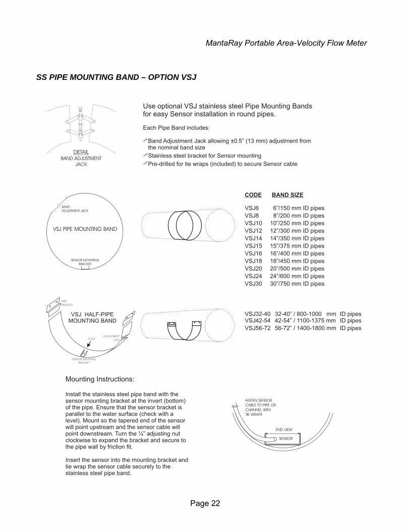
SS PIPE MOUNTING BAND – OPTION VSJ
CODE BAND SIZE
VSJ6 6”/150 mm ID pipes
VSJ8 8”/200 mm ID pipes
VSJ10 10”/250 mm ID pipes
VSJ12 12”/300 mm ID pipes
VSJ14 14”/350 mm ID pipes
VSJ15 15”/375 mm ID pipes
VSJ16 16”/400 mm ID pipes
VSJ18 18”/450 mm ID pipes
VSJ20 20”/500 mm ID pipes
VSJ24 24”/600 mm ID pipes
VSJ30 30”/750 mm ID pipes
VSJ32-40 32-40” / 800-1000 mm ID pipesVSJ42-54 42-54” / 1100-1375 mm ID pipes
VSJ56-72 56-72” / 1400-1800 mm ID pipes
DETAILBAND ADJUSTMENT
JACK
Use optional VSJ stainless steel Pipe Mounting Bandsfor easy Sensor installation in round pipes.
Each Pipe Band includes:
Band Adjustment Jack allowing ±0.5” (13 mm) adjustment fromthe nominal band size
Stainless steel bracket for Sensor mounting
Pre-drilled for tie wraps (included) to secure Sensor cable
�
�
�
VSJ PIPE MOUNTING BAND
BAND
ADJUSTMENT JACK
SENSOR MOUNTING
BRACKET
Mounting Instructions:
Install the stainless steel pipe band with thesensor mounting bracket at the invert (bottom)of the pipe. Ensure that the sensor bracket isparallel to the water surface (check with alevel). Mount so the tapered end of the sensorwill point upstream and the sensor cable willpoint downstream. Turn the ¼” adjusting nutclockwise to expand the bracket and secure tothe pipe wall by friction fit.
Insert the sensor into the mounting bracket andtie wrap the sensor cable securely to thestainless steel pipe band.
FASTEN SENSOR
CABLE TO PIPE OR
CHANNEL WITH
TIE WRAPS
SENSOR
END VIEW
VSJ HALF-PIPEMOUNTING BAND
ADJUSTMENT
JACK
SENSOR MOUNTING
BRACKET
END
BRACKET
FLOW