
Manitoba – Minnesota Transmission Project Environmental ... · manitoba – minnesota...
124
MANITOBA – MINNESOTA TRANSMISSION PROJECT Environmental Impact Statement PROJECT DESCRIPTION CHAPTER 2 SEPTEMBER 2015
Transcript of Manitoba – Minnesota Transmission Project Environmental ... · manitoba – minnesota...

MANITOBA – MINNESOTA TRANSMISSION PROJECT Environmental Impact Statement
PROJECT DESCRIPTION CHAPTER 2 SEPTEMBER 2015

MANITOBA – MINNESOTA TRANSMISSION PROJECT ENVIRONMENTAL IMPACT STATEMENT
2: PROJECT DESCRIPTION TABLE OF CONTENTS
TABLE OF CONTENTS Page
2 PROJECT DESCRIPTION ..................................................................... 2-1
2.1 Introduction .................................................................................. 2-1
2.2 Project Need and the Public Utility Board Review ........................ 2-1
2.3 Regulatory Approvals ................................................................... 2-2
2.3.1 General ................................................................................................. 2-2
2.3.2 Provincial Requirements....................................................................... 2-2
2.3.2.1 Primary Requirements .......................................................... 2-2
2.3.2.2 Other Requirements and Considerations............................. 2-3
2.3.3 Federal Requirements .......................................................................... 2-8
2.3.3.1 Primary Requirements .......................................................... 2-8
2.3.3.2 Other Requirements and Considerations............................. 2-8
2.4 Project Component Overview .................................................... 2-14
2.4.1 D604I 500 kV Transmission Line ....................................................... 2-14
2.4.1.1 Existing Transmission Corridors ........................................ 2-14
2.4.1.2 New Right-of-Way ............................................................... 2-17
2.4.2 Modifications/Additions to Existing Stations ...................................... 2-18
2.4.2.1 Dorsey Converter Station ................................................... 2-18
2.4.2.2 Riel Converter Station ........................................................ 2-18
2.4.2.3 Glenboro South Station ...................................................... 2-18
2.5 Alternative Project Designs ........................................................ 2-19
2.6 Project Location ......................................................................... 2-21
2.6.1 Southern Loop Transmission Corridor ............................................... 2-21
2.6.2 Riel–Vivian Transmission Corridor ..................................................... 2-23
2.6.3 Transmission Line within New Right-of-Way ..................................... 2-23
2.7 Engagement Purpose and Goals ............................................... 2-24
2.7.1 Public Engagement............................................................................. 2-25
September 2015 2-i

MANITOBA – MINNESOTA TRANSMISSION PROJECT ENVIRONMENTAL IMPACT STATEMENT 2: PROJECT DESCRIPTION TABLE OF CONTENTS
2.7.2 First Nation and Metis Engagement ................................................... 2-25
2.8 Design Philosophy ..................................................................... 2-26
2.9 Transmission Line Design and Mitigation Details ....................... 2-28
2.9.1 Transmission Line Routing ................................................................. 2-28
2.9.2 Tower Type and Span ........................................................................ 2-28
2.9.2.1 Structures within Existing Transmission Corridors ............ 2-31
2.9.2.2 Structures within New Right-of-Way .................................. 2-33
2.9.3 Conductors .......................................................................................... 2-34
2.9.4 Insulators ............................................................................................. 2-36
2.9.5 Optical Ground Wire ........................................................................... 2-37
2.9.6 Tower Location ................................................................................... 2-38
2.9.7 Right-of-Way Width............................................................................. 2-38
2.10 Environmental Policy and Management System ........................ 2-39
2.10.1 Environmental Management Plans .................................................... 2-40
2.10.1.1 Construction Safety, Security and Emergency Response Plans .................................................................. 2-40
2.10.1.2 Solid Waste and Hazardous Materials Management ........ 2-41
2.10.1.3 Access Management Plan .................................................. 2-41
2.11 Transmission Line Construction Key Mitigation Details .............. 2-41
2.11.1 Wildlife and Wildlife Habitat ................................................................ 2-42
2.11.2 Fish and Fish Habitat .......................................................................... 2-43
2.11.3 Vegetation and Wetlands ................................................................... 2-44
2.11.4 Traditional Land and Resource Use and Heritage Resources.......... 2-44
2.11.5 Infrastructure and Services ................................................................ 2-45
2.11.6 Employment and Economy ................................................................ 2-45
2.11.7 Agriculture ........................................................................................... 2-46
2.11.8 Land and Resource Use ..................................................................... 2-46
2.11.9 Human and Ecological Health ............................................................ 2-46
2.12 Construction Process ................................................................. 2-47
2.12.1 Schedule and Workforce .................................................................... 2-47
2.12.2 Mobilizing Staff and Equipment .......................................................... 2-47
2-ii September 2015

MANITOBA – MINNESOTA TRANSMISSION PROJECT ENVIRONMENTAL IMPACT STATEMENT
2: PROJECT DESCRIPTION TABLE OF CONTENTS
2.12.3 Access Route and Bypass Trail Development .................................. 2-48
2.12.4 Right-of-Way Clearing and Geotechnical Investigations ................... 2-49
2.12.4.1 Right-of-Way Clearing ........................................................ 2-49
2.12.4.2 Geotechnical Investigations ............................................... 2-51
2.12.5 Transmission Tower Construction and Conductor Stringing ............. 2-52
2.12.6 Marshalling Yards ............................................................................... 2-58
2.12.7 Borrow Sources .................................................................................. 2-59
2.12.8 Accommodations and Construction Camps ...................................... 2-60
2.12.9 Demobilization .................................................................................... 2-61
2.13 Transmission Line Operation and Maintenance ......................... 2-62
2.13.1 Inspection Patrols ............................................................................... 2-62
2.13.2 Workforce Requirements .................................................................... 2-62
2.13.3 Vegetation Management .................................................................... 2-63
2.13.4 Electric and Magnetic Fields and Corona .......................................... 2-65
2.14 Transmission Line Decommissioning ......................................... 2-65
2.15 Station Modifications and Additions ........................................... 2-66
2.15.1 Dorsey Converter Station ................................................................... 2-67
2.15.1.1 Dorsey Converter Station Activity Overview ...................... 2-67
2.15.1.2 Site Preparation .................................................................. 2-69
2.15.1.3 Oil Storage and Containment ............................................. 2-69
2.15.1.4 Station Grounding ............................................................... 2-71
2.15.1.5 Station Protection ............................................................... 2-71
2.15.1.6 Communications ................................................................. 2-71
2.15.1.7 Foundations ........................................................................ 2-72
2.15.1.8 Steel Structures .................................................................. 2-74
2.15.1.9 Station Lighting ................................................................... 2-76
2.16 Riel Converter Station ................................................................ 2-76
2.16.1 Riel Converter Station Activity Overview ........................................... 2-77
2.16.1.1 Site Preparation .................................................................. 2-78
2.16.1.2 Oil Storage and Containment ............................................. 2-78
September 2015 2-iii
MANITOBA – MINNESOTA TRANSMISSION PROJECT ENVIRONMENTAL IMPACT STATEMENT 2: PROJECT DESCRIPTION TABLE OF CONTENTS
2.16.1.3 Communications ................................................................. 2-78
2.16.1.4 Protection ............................................................................ 2-79
2.16.1.5 Ground Grid ........................................................................ 2-80
2.16.1.6 Foundations ........................................................................ 2-80
2.16.1.7 Steel Structures .................................................................. 2-80
2.17 Glenboro South Station .............................................................. 2-81
2.17.1 Glenboro South Station Construction Activity .................................... 2-82
2.17.1.1 Site Preparation .................................................................. 2-83
2.17.1.2 Oil Storage and Containment ............................................. 2-83
2.17.1.3 Protection ............................................................................ 2-83
2.17.1.4 Station Grounding ............................................................... 2-84
2.17.1.5 Foundations ........................................................................ 2-84
2.17.1.6 Steel Structures .................................................................. 2-85
2.17.1.7 Communications ................................................................. 2-85
2.17.1.8 Station Lighting ................................................................... 2-85
2.17.2 Transmission and Distribution Line Relocation and Salvage ............ 2-85
2.17.3 Relocation of Existing Equipment ...................................................... 2-86
2.18 Station Operation and Maintenance ........................................... 2-86
2.18.1 Environmental Emissions and Discharges during Station Operation ............................................................................................ 2-87
2.18.1.1 Electric and Magnetic Fields and Corona .......................... 2-87
2.18.1.2 Audible Equipment Noise ................................................... 2-87
2.18.1.3 Solid Waste and Hazardous Materials Management ........ 2-87
2.18.1.4 Sulphur Hexafluoride and Carbon Tetrafluoride ................ 2-87
2.18.1.5 Insulating Oil ....................................................................... 2-88
2.19 Station Decommissioning........................................................... 2-88
2.20 Easement Procurement Procedures and Compensation ........... 2-88
2.20.1 Land Compensation ........................................................................... 2-89
2.20.2 Construction Damage Compensation ................................................ 2-90
2.20.3 Structure Impact Compensation ......................................................... 2-90
2.20.4 Ancillary Damage Compensation ....................................................... 2-91
2-iv September 2015

MANITOBA – MINNESOTA TRANSMISSION PROJECT ENVIRONMENTAL IMPACT STATEMENT
2: PROJECT DESCRIPTION TABLE OF CONTENTS
2.21 References ................................................................................ 2-92
2.21.1 Literature Cited ................................................................................... 2-92
September 2015 2-v

MANITOBA – MINNESOTA TRANSMISSION PROJECT ENVIRONMENTAL IMPACT STATEMENT 2: PROJECT DESCRIPTION LIST OF TABLES
LIST OF TABLES Page
Table 2-1 Provincial Environmental Statutes ....................................................................... 2-3 Table 2-2 Federal Environmental Statutes ......................................................................... 2-10 Table 2-3 Overhead Systems Clearance Requirements ................................................... 2-27 Table 2-4 Southern Loop Transmission Corridor Tower Structure Types......................... 2-32 Table 2-5 Riel–Vivian Transmission Corridor Existing Tower Structure Types ................ 2-32 Table 2-6 Riel–Vivian Transmission Corridor New Tower Structure Types ...................... 2-33 Table 2-7 New Right-of-Way from Existing Corridor to U.S. Border ................................. 2-34 Table 2-8 Current Phase Conductor Specifications ........................................................... 2-35 Table 2-9 Current Insulator String Design Basic Information ............................................ 2-36
2-vi September 2015

MANITOBA – MINNESOTA TRANSMISSION PROJECT ENVIRONMENTAL IMPACT STATEMENT
2: PROJECT DESCRIPTION LIST OF FIGURES
LIST OF FIGURES Page
Figure 2-1 Western Modifications to M602F using a portion of new tower construction for its line ............................................................................................................. 2-16
Figure 2-2 Eastern Modifications to M602F using a portion of new tower construction for its line ............................................................................................................. 2-17
Figure 2-3 Southern Loop Transmission Corridor – Transmission Line Crossovers ......... 2-22 Figure 2-4 Typical 500 kV Self-Supporting Steel Lattice Structure .................................... 2-29 Figure 2-5 Typical 500 kV Guyed Steel Lattice Structure ................................................... 2-30 Figure 2-6 Triple-conductor bundles for each of the three phases, suspended by
insulators ............................................................................................................. 2-35 Figure 2-7 Insulator string of interconnect glass discs ........................................................ 2-36 Figure 2-8 Skywires strung along the tops of towers to provide lightning protection ......... 2-37 Figure 2-9 Bird diverters installed on skywires in areas of high collision potential ............ 2-42 Figure 2-10 Machine free zone in riparian habitat to mitigate potential effects on fish
and fish habitat.................................................................................................... 2-43 Figure 2-11 Machine free zone near an environmentally sensitive site to mitigate
potential effects on heritage resources .............................................................. 2-45 Figure 2-12 Current Transmission Line Construction Schedule (*Subject to change,
pending regulatory approval).............................................................................. 2-48 Figure 2-13 Riparian Buffer in transmission line ROW ......................................................... 2-49 Figure 2-14 Vegetation management with a mulcher along the ROW ................................. 2-50 Figure 2-15 Danger tree removal by a feller buncher ........................................................... 2-51 Figure 2-16 A test pit located at a tower foundation as part of geotechnical excavations
for specialty towers ............................................................................................. 2-52 Figure 2-17 Installation of tower foundations and anchors ................................................... 2-53 Figure 2-18 A tower structure assembled at a marshalling yard erected by crane .............. 2-53 Figure 2-19 Stringing Conductor ............................................................................................ 2-54 Figure 2-20 Mat foundations used to support self-supporting suspension lattice steel
structures ............................................................................................................ 2-55 Figure 2-21 Pile foundations used to support self-supporting suspension lattice steel
structures ............................................................................................................ 2-55 Figure 2-22 Erecting Tower by Crane .................................................................................... 2-56 Figure 2-23 A tower structure assembled at a marshalling yard erected by helicopter ....... 2-57 Figure 2-24 Conductors are transported to the site in reels before suspension from the
insulator strings ................................................................................................... 2-58
September 2015 2-vii

MANITOBA – MINNESOTA TRANSMISSION PROJECT ENVIRONMENTAL IMPACT STATEMENT 2: PROJECT DESCRIPTION LIST OF FIGURES
Figure 2-25 Marshalling yards store construction materials and equipment for the construction site .................................................................................................. 2-59
Figure 2-26 A borrow pit located along the transmission line ROW supplies aggregates for the Project ...................................................................................................... 2-60
Figure 2-27 A mobile construction camp supports construction workers ............................. 2-61 Figure 2-28 Aerial Photo of Dorsey Converter Station .......................................................... 2-67 Figure 2-29 Switchyard........................................................................................................... 2-68 Figure 2-30 Current Station Schedule (*Subjet to change, pending regulatory approval) ... 2-68 Figure 2-31 Dorsey Expansion ............................................................................................... 2-69 Figure 2-32 Oil Containment for a Transformer .................................................................... 2-70 Figure 2-33 Oil Containment for Multiple Pieces of Equipment ............................................ 2-70 Figure 2-34 Example of two caps on deep pile foundations ................................................. 2-72 Figure 2-35 Foundation (farthest in photo) is an example of a slab on grade foundation ... 2-73 Figure 2-36 Example of slab on grade foundation on piles ................................................... 2-73 Figure 2-37 Example of manufactured steel supporting structures for a capacitor .............. 2-74 Figure 2-38 Example of tubular steel structures for bus work and related equipment ......... 2-75 Figure 2-39 Example of steel lattice structures ..................................................................... 2-75 Figure 2-40 Riel Converter Station ........................................................................................ 2-76 Figure 2-41 Aerial Photo of Riel Converter Station ............................................................... 2-77 Figure 2-42 Glenboro South Station ...................................................................................... 2-82
2-viii September 2015

MANITOBA – MINNESOTA TRANSMISSION PROJECT ENVIRONMENTAL IMPACT STATEMENT
2: PROJECT DESCRIPTION LIST OF MAPS
LIST OF MAPS
Map 2-1 Project Components Map 2-2 Existing Transmission Corridor Map 2-3 New Right-of-way Map 2-4 Dorsey Converter Station Map 2-5 Riel Converter Station Map 2-6 Glenboro South Station Map 2-7 New Right-of-way Width
September 2015 2-ix

MANITOBA – MINNESOTA TRANSMISSION PROJECT ENVIRONMENTAL IMPACT STATEMENT 2: PROJECT DESCRIPTION APPENDICES
APPENDICES Appendix 2A Station Equipment List
2-x September 2015

MANITOBA – MINNESOTA TRANSMISSION PROJECT ENVIRONMENTAL IMPACT STATEMENT
2: PROJECT DESCRIPTION ABBREVIATIONS AND ACRONYMS
ABBREVIATIONS AND ACRONYMS AC alternating current
ACSR aluminum core steel reinforced
AMP Access Management Plan
CEnvPP Construction Environmental Protection Plan
CNR
CPR
Canadian National Railway
Canadian Pacific Railway
CRA commercial, recreational. or Aboriginal fishery
CSA Canadian Standard Association
CT current transformer
CVT capacitive voltage transformer
DFO Fisheries and Oceans Canada
EIS environmental impact statement
EMF electric and magnetic field
EMS Environmental Management System
EPP Environmental Protection Plan
EPRI Electric Power Research Institute
GIS gas insulated switch
GNTL Great Northern Transmission Line
GTC Georgia Transmission Complex
GWWD Greater Winnipeg Water District
ha hectare
IPL international power line
ISO International Organization for Standardization
kV kilovolt
MASC Manitoba Agricultural Services Corporation
MB Manitoba
MH Manitoba Hydro
September 2015 2-xi

MANITOBA – MINNESOTA TRANSMISSION PROJECT ENVIRONMENTAL IMPACT STATEMENT 2: PROJECT DESCRIPTION ABBREVIATIONS AND ACRONYMS
MMTP Manitoba–Minnesota Transmission Project
MOU Memorandum of Understanding
MRO Midwest Reliability Organization
MTS Manitoba Telecom Services
NFAT Needs For and Alternatives To
NERC North American Reliability Electric Corporation
OATT Open Access Transmission Tariff
OPGW optical protection ground wire
PDA Project development area
PEP public engagement process
PR provincial road
PST phase shifting transformer
PT potential transformer
PTH provincial trunk highway
PUB Public Utilities Board
ROW right-of-way
RVTC Riel-Vivian Transmission Corridor
SLTC Southern Loop Transmission Corridor
SOP Standard Operating Procedure
TCH TransCanada Highway
WMA Wildlife Management Area
2-xii September 2015

MANITOBA – MINNESOTA TRANSMISSION PROJECT ENVIRONMENTAL IMPACT STATEMENT
2: PROJECT DESCRIPTION GLOSSARY OF TECHNICAL TERMS
GLOSSARY OF TECHNICAL TERMS Aboriginal Peoples Includes First Nation, Inuit and Métis, as defined in subsection 35
(2) of the Constitution Act, 1982 (Canada)
Access road A road that affords access into and out of a "construction" area
Access trail A trail that affords access into and out of a construction area
Adverse effects Negative effects on the environment and people that may result from a proposed project
Agricultural biosecurity The protection of crops and livestock systems against the threats to production from disease, pests and invasive species
Alternating current Is the oscillating (back and forth) flow of electrical current, whereas dc (direct current) is the unidirectional continuous flow of electrical current. AC is the common household electrical current and is used in transmission lines; DC is the form of current produced by battery (e.g., in a flashlight). High voltage DC (HVdc) transmission is used in Manitoba for some transmission facilities (e.g., between Limestone Generating Station and Winnipeg).
Alternative means of carrying out a project
The various technically and economically feasible ways, other than the proposed way, for a project to be implemented or carried out. Examples include other project locations, different routes and methods of development, and alternative methods of project implementation or mitigation.
Ancillary Damage Compensation
A one-time payment (for each occurrence) to landowners where Manitoba Hydro’s use of the right-of-way directly or indirectly affects the use of the property
Angle towers Towers located where there is a change in route direction and are subject to additional longitudinal loads arising from the tension of the conductors
Bird diverters Devices placed on the skywire to make the transmission line more visible to birds
Blasting The act of causing an explosion, consisting of a wave of increased atmospheric pressure followed immediately by a wave of decreased pressure
September 2015 2-xiii

MANITOBA – MINNESOTA TRANSMISSION PROJECT ENVIRONMENTAL IMPACT STATEMENT 2: PROJECT DESCRIPTION GLOSSARY OF TECHNICAL TERMS
Borrow source Location of material (usually sand or gravel) for construction purposes
Bypass trail A trail that leaves the ROW to circumvent an obstruction, such as steep terrain, saturated soils, etc., and returns to the ROW
Conductor Any material that will readily carry a flow of electricity. In the context of transmission lines, each of the three conductors or conductor bundles comprising an AC circuit, is referred to as a conductor
Conductor stringing The process of suspending the conductor from insulators attached to the transmission line towers or structures
Construction Damage Compensation
A one-time payment (for each occurrence) to landowners for damages caused by construction activities
Corona discharge An electrical discharge that occurs when the electric fields near the transmission line exceeds the breakdown strength of air. When a corona discharge occurs, the air rapidly expands, causing audible noise that sounds like a hissing or crackling sound, or a 120 Hz hum. It also releases a small amount of current in to the air that produces radio noise.
Dead-end towers Towers at the terminations of the line subject to loads arising from the unbalanced effect of conductor tension on one side of the structure
Decomissioning Planned shut-down, dismantling and removal of a building, equipment, plant or other facilities from operation or usage, and may include site clean-up and restoration
Demobilization The removal of personnel, machinery, materials and other support infrastructure and services from a site after construction is complete
Easement The permission or right to use a defined area of land for a specific purpose such as transmission line rights-of-way. Transmission line easements give Manitoba Hydro the right of access to the right-of-way to construct, operate and maintain the transmission line
Electric and magnetic fields Invisible lines of force surrounding objects that generate, transmit, or use electricity, such as electronic devices, tools and appliances, electrical wiring, and transmission lines
2-xiv September 2015

MANITOBA – MINNESOTA TRANSMISSION PROJECT ENVIRONMENTAL IMPACT STATEMENT
2: PROJECT DESCRIPTION GLOSSARY OF TECHNICAL TERMS
Environmental Management System
Part of an organization‘s overall management practices related to environmental affairs. It includes organizational structure, planning activities, responsibilities, practices, procedures, processes and resources for developing, implementing, achieving, reviewing and maintaining an environmental policy. This approach is often formally carried out to meet the requirements of the International Organization for Standardization (ISO) 14000 series.
Environmental Protection Plan
Within the framework of an Environmental Protection Program, an Environmental Protection Plan prescribes measures and practices to avoid and limit potential environmental effects of a proposed project. A user-friendly guide for the contractor and Manitoba Hydro that includes information such as a brief project description; updated construction schedule; summary identifying environmental sensitivities and mitigation actions; listing of all federal, provincial or municipal approvals, licences, or permits that are required for the project; a description of general corporate practices and specific mitigating actions for the various construction and maintenance activities; emergency response plans, training and information; and environmental/engineering monitoring plans and reporting protocols.
Environmental Protection Program
Provides a framework for delivery, management and monitoring of environmental protection activities in keeping with issues identified in the environmental assessment, regulatory requirements and public expectation
Environmentally Sensitive Site
Locations, features, areas, activities or facilities that were identified in the Manitoba-Minnesota Transmission Project environmental impact statement to be ecologically, socially, economically or culturally important or sensitive to disturbance and require protection during construction and operation of the Project
Existing transmission corridor A term to describe the existing Southern Loop and Riel–Vivian transmission corridors
Final Preferred Route Based on the environmental assessment and Round 3 of the engagement processes, the Final Preferred Route is the best balanced approach of all disciplines’ understanding. The Final Preferred Route is submitted with the environmental impact statement.
September 2015 2-xv

MANITOBA – MINNESOTA TRANSMISSION PROJECT ENVIRONMENTAL IMPACT STATEMENT 2: PROJECT DESCRIPTION GLOSSARY OF TECHNICAL TERMS
Gas insulated switch Electrical switchgear that uses gas (typically SF6) as the insulating medium (as opposed to air or oil); refers also to stations designed to use GIS equipment
Geotechnical investigations Involve the excavation of test pits and in some instances such as angle towers soil drilling to create a soil profile that is used by civil designers in the development of specialty foundations
Ground grid The ground grid provides a means to make sure personnel, public and equipment safety. One of its purposes is to make sure a person within a station and up to 1 m outside the station fence is not exposed to critical electrical shock under normal and fault conditions.
Grubbing The act of removing roots from soil using a root rake, harrow or similar device
Guideline Non-mandatory, supplemental information about acceptable methods, procedures and standards for implementation of requirements found in legislation, policies and directives
Guyed suspension steel lattice
A steel structure that is based on a single foundation at the centre point of its base and stabilized typically by four guy wires
Guyes or guy wires Supporting wires that are used to stabilize some transmission line structures
Hazardous substance Any substance which, by reason of being explosive, flammable, poisonous, corrosive, oxidizing or otherwise harmful, is likely to cause death or injury
Heritage resource Any work or assembly of works of nature or of human endeavour that is of value for its archaeological, palaeontological, pre-historic, historic, cultural, natural, scientific or aesthetic features, and may be in the form of sites or objects or a combination thereof (The Heritage Resources Act)
International power line Facilities constructed or operated for the purpose of transmitting electricity from or to a place in Canada to or from a place outside Canada
Kilovolt The unit of electromotive force or electrical pressure equivalent to 1000 volts (V)
Land Compensation A one-time payment (for each occurrence) to landowners granting an easement for the ROW
2-xvi September 2015

MANITOBA – MINNESOTA TRANSMISSION PROJECT ENVIRONMENTAL IMPACT STATEMENT
2: PROJECT DESCRIPTION GLOSSARY OF TECHNICAL TERMS
Machine-free zone A zone located adjacent to the riparian area in which no ground disturbance will take place but where harvesting may be permitted by reaching in with harvesting equipment (approximate reach is 7 m)
Marshalling yard An open area used to stock-pile, store and assemble construction materials
North American Reliability Electric Corporation
Develops and enforces reliability standards; assesses adequacy annually via a 10-year forecast, and summer and winter forecasts; monitors the bulk power system; and educates, trains and certifies industry personnel (NERC 2011)
Optical protection ground wire
Provides both lightning protection for a transmission line and communications for line control and protection
Preferred route Presented during Round 3 of the engagement processes, the preferred route was determined as the best balanced choice of the refined alternative routes and was based on feedback received during the Public and First Nation and Metis engagement processes, biophysical, socio-economic, cost and technical considerations, as identified through the transmission line routing process.
Project development area The footprint of the Project where physical disturbance is expected to occur
Public engagement process The process that informs individuals, including stakeholder groups and the public, of the Manitoba-Minnesota Transmission Project and allows them opportunities to provide input into in the routing and environmental assessment work being undertaken
Reliability based design Any design methodology that incorporates the principles of reliability analysis (the consistent evaluation of design risk using probability theory) either explicitly or otherwise
Riel–Vivian Transmission Corridor
An existing Manitoba Hydro owned transmission corridor that contains M602F and Bipole III 500kv transmission lines and runs from Riel Converter Station to near Vivian, MB
Right-of-way The legal right to pass along a specific route, for transportation purposes (e.g., transmission lines), through property that belongs to another, which is established by easement from landowners
Riparian buffer The retention of shrub and herbaceous vegetation in riparian habitats, which include streams, rivers, lakes and wetlands in the Project development area
September 2015 2-xvii

MANITOBA – MINNESOTA TRANSMISSION PROJECT ENVIRONMENTAL IMPACT STATEMENT 2: PROJECT DESCRIPTION GLOSSARY OF TECHNICAL TERMS
Self-supporting suspension lattice
A steel structure supported on four separately founded legs
Southern Loop Transmission Corridor
A dedicated transmission corridor between the Dorsey Converter Station (near Rosser) and the Riel Converter Station (east of Winnipeg). It will accommodate multiple transmission lines necessary for system reliability and meeting future energy demands in southern Manitoba.
Structure Impact Compensation
A one-time payment to landowner for each tower located on agricultural lands
Switchyard An area within a substation used for switching
Tangent towers Towers installed in straight sections of the line
Termination points The start and end points of a transmission line at an electrical station. For Manitoba-Minnesota Transmission Project, this includes Dorsey Converter Station and the Iron Range Station.
Tower spotting A process by which transmission towers are located on the landscape along the Final Preferred Route with consideration of engineering, environmental and socio-economic factors
Transmission line A linear arrangement of towers and conductors that carries electricity from generating stations and transmission stations to load centres like communities and industries to meet electrical needs
2-xviii September 2015
MANITOBA – MINNESOTA TRANSMISSION PROJECT ENVIRONMENTAL IMPACT STATEMENT
2: PROJECT DESCRIPTION
2 Project Description
2.1 Introduction Manitoba Hydro is proposing to construct and operate a 500 kilovolt (kV) alternating current (AC) international power line (IPL) in southeastern Manitoba that includes additions and upgrades to three associated transmission stations at Dorsey, Riel and Glenboro South, and modifications to two existing international power lines. The Manitoba–Minnesota Transmission Project (MMTP, or the Project) is required to:
• deliver contracted quantities of power to and from the United States pursuant to new long-term power purchase agreements
• improve reliability by increasing capacity in emergency and drought situations
• increase Manitoba Hydro’s capacity to participate in organized electricity markets in the United States
Subject to regulatory approvals, the projected in-service date of the Project is 2020. The estimated cost is $350 million. The Project consists primarily of a 213 km single-circuit, 500 kV AC transmission line starting at the existing Dorsey Converter Station northwest of Winnipeg, connecting at the Manitoba-Minnesota border to a new transmission line in The U.S. It is called the Great Northern Transmission Line (GNTL), and Minnesota Power is the proponent for the regulatory process. GNTL will terminate at a new 500 kV substation adjacent to the existing Blackberry substation in Minnesota in the Iron Range, located approximately 100 km northwest of Duluth, Minnesota. The approximate total length of the interconnected transmission lines between the Dorsey Converter Station and Iron Range Station is 600 km.
This chapter describes the background and the details associated with various components of the Project and how they were determined.
2.2 Project Need and the Public Utility Board Review
Electricity use in Manitoba is projected to grow over the next two decades, requiring new sources of electricity that will be needed to supply the province by 2023. To meet this need, Manitoba Hydro is continuing to invest in hydroelectric generation. Manitoba Hydro has identified a development plan that provides an adequate supply of electricity is available to meet all firm domestic load requirements. The surplus of power within the integrated system provides an opportunity to create sales revenue through increasing the transmission capacity between Manitoba and U.S. markets. The Project will support future power sales.
September 2015 2-1

MANITOBA – MINNESOTA TRANSMISSION PROJECT ENVIRONMENTAL IMPACT STATEMENT 2: PROJECT DESCRIPTION
In accordance with Manitoba Order in Council 128 / 2013 issued pursuant to section 107 of The Public Utilities Board Act, C.C.S.M. c. P280, the Public Utilities Board (PUB) conducted a Needs For and Alternatives To (NFAT) review of development plans proposed by Manitoba Hydro. One of the development plans included the construction of the Manitoba-Minnesota 500 kV IPL. During the proceedings, the need for the Manitoba-Minnesota 500kV IPL was evaluated. The PUB's report was provided to the Province of Manitoba in June 2014, and contained a recommendation to move forward with the Manitoba-Minnesota 500kV IPL.
2.3 Regulatory Approvals
2.3.1 General This environmental impact statement (EIS) was prepared in response to the Project Final Scoping Document, issued on June 24 2015 by Manitoba Conservation and Water Stewardship’s Environmental Approvals Branch. The Final Scoping Document represents the Guidelines for the EIS, based on public/regulatory review. The EIS is intended to meet the requirements of The Environment Act (Manitoba), as well as the National Energy Board Act (NEB Act) and the Canadian Environmental Assessment Act, 2012 (CEAA 2012). In light of this, the Scoping Document integrated the requirements of the Environment Act Proposal Report Guidelines (MCWS 2014), National Energy Board Electricity Regulations (NEB 2015), and CEAA 2012. Chapter 6 of the NEB Electricity Filing Manual was also considered as guidance (NEB 2015). This section discusses the various provincial and federal regulatory requirements that were considered for this Project. It is anticipated that regulatory approval decisions for this Project would occur in 2017. Subject to these approvals, construction is anticipated to begin in 2017/18 with an in-service date of 2020.
2.3.2 Provincial Requirements
2.3.2.1 Primary Requirements The Project is a “development” pursuant to the Classes of Development Regulation (M.R. 164/88) under The Environment Act (Manitoba) (C.C.S.M. c. E125). The construction of electrical transmission lines greater than 230 kV and associated facilities is considered a Class 3 Development pursuant to the Classes of Development Regulation and is subject to licensing under section 12 of the Act. The Licensing Procedures Regulation (163/88) outlines information requirements for proposals under the Act. The Act is administered by the Environmental Approvals Branch of Manitoba Conservation and Water Stewardship.
In addition to providing the framework for the overall environmental assessment and approvals process, the Act authorizes regulations that address aspects such as recovery of public hearing costs, onsite wastewater management, litter, and waste disposal grounds.
2-2 September 2015

MANITOBA – MINNESOTA TRANSMISSION PROJECT ENVIRONMENTAL IMPACT STATEMENT
2: PROJECT DESCRIPTION
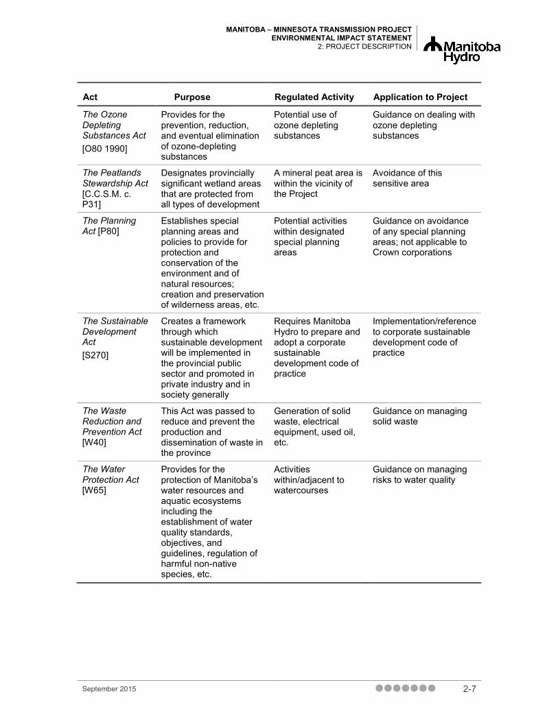
2.3.2.2 Other Requirements and Considerations Various environmental authorizations and notifications will be required under provincial legislation to undertake activities ancillary to the construction and operation of the Project and some regulatory requirements provide guidance in dealing with Project activities. The various provincial environmental statutes that were considered are listed in Table 2-1.
As indicated previously, it should be noted that this Project has already been reviewed by a panel of the Public Utilities Board of Manitoba (PUB Panel) during a public proceeding that commenced in August 2013 (PUB 2013). The justification for the new IPL was presented as part of a Manitoba Hydro development plan alternatives. This “Needs For and Alternatives To” (NFAT) review included the appointment of independent expert consultants to examine Manitoba Hydro’s plans, file expert reports and testify. The hearing commenced with the filing of Manitoba Hydro’s business case, followed by two rounds of written information requests from the PUB Panel and interveners, evidence filed by interveners, one round of information requests and an oral hearing from March 3 to May 26, 2014. After the NFAT review concluded, the PUB Panel issued a report with recommendations to the Government of Manitoba regarding Manitoba Hydro’s development plan (PUB 2014). The report recommended that Manitoba Hydro be given approval to proceed with the requirements necessary for the construction of the proposed 500 kV international power line, as it was concluded that the interconnection “provides increased firm transmission access extending into Minnesota, provides important, increased reliability, and supports import and export of electricity.” This recommendation led to the issuance of an Order in Council on December 10, 2014 authorizing Manitoba Hydro to enter into agreements and take all necessary actions related to the construction and operation of a new transmission interconnection, pursuant to section 16(1), (e) and (f) of The Manitoba Hydro Act (C.C.S.M. c.H190, s.2).
Table 2-1 Provincial Environmental Statutes
Act Purpose Regulated Activity Application to Project
PERMIT REQUIRED
The Crown Lands Act [C340]
Protection, control, and prudent use of Crown lands
Entry, work and vehicle use
Permits required authorizing specified work to be performed on and authorizing entry for the purpose of the work
The Dangerous Goods Handling And Transportation Act [D12]
Regulates aspects of dangerous goods that affect the environment or public health, including handling, disposal, etc.
Handling, and disposal of dangerous materials, including accidental spills cleanup/reporting
Permit required for carriers, and to store/dispose of petroleum/hazardous waste
September 2015 2-3

MANITOBA – MINNESOTA TRANSMISSION PROJECT ENVIRONMENTAL IMPACT STATEMENT 2: PROJECT DESCRIPTION
Act Purpose Regulated Activity Application to Project
The Fires Prevention And Emergency Response Act [F80]
Provides for the control of activities concerned with prevention, detection, and extinguishment of fires
Any activities associated with combustible materials
Work camp occupancy permit required
The Forest Act [F150]
Provides for the regulation and administration of forests within Crown lands and provincial forests
Cutting/removing timber on Crown lands
Permit required to enter forest land to cut or remove timber
The Heritage Resources Act [H 39.1]
Provides for the designation/protection of heritage objects and resources/sites.
Conducting heritage field studies and managing/protecting heritage resources that are discovered
Permit required for conducting heritage investigations
The Highways Protection Act [H50]
Protects the safety of persons using the highways, and controls the location, construction, and use of entrances/exits from certain highways; adjacent land use or structures erected along certain highways
Establishment of access roads and tower placement
Permits required to construct and entrance/exit from certain highways and to erect a structure other than an advertising sign within a controlled area (between the limited access highway or freeway and the control line)
The Mines and Minerals Act [M162]
Provides for the administration of mines and minerals of Manitoba, which includes the right to the ores, minerals, and mines upon or under the surface in Crown lands
Establishment and use of quarries/borrow areas for construction materials
Surface (casual or exploration) permit or lease required (under Crown Lands Act) to gain access to Crown lands to establish/use a quarry
The Pesticides and Fertilizers Control Act [P40]
Addresses the supply, sale, distribution, and application of pesticides or fertilizers
Potential use of pesticides for vegetation control
Licence required for the applicator and Pesticide Use Permit required
2-4 September 2015

MANITOBA – MINNESOTA TRANSMISSION PROJECT ENVIRONMENTAL IMPACT STATEMENT
2: PROJECT DESCRIPTION
Act Purpose Regulated Activity Application to Project
The Provincial Parks Act [P20]
Provides for the conservation and management of flora and fauna, preservation of specified areas and objects of geological, cultural, ecological, or other scientific interest.
Project ROW crosses Duff Roblin Heritage Provincial Park
Permits are required for constructing trails, establishing winter roads, grooming snowmobile trails, snow clearing on roads, trails, or bodies of water, excavating, blasting, or drilling, cutting trees, burning for the purpose of clearing trees or brush, applying pesticide, drilling wells
The Public Health Act [P210]
Relates to the preservation of life and health, including conditions or circumstances that may contaminate or pollute food, air or water.
Food handling establishments in camps
Food handling permit required if camps include a kitchen
The Water Rights Act [W80]
Provides for the administration of matters related to the construction or operation of certain water control works
Ground water exploration activities
Permit is required to withdraw water from a provincial surface or ground water source, including exploration activities
The Wildfires Act [W128]
Provides for the avoidance of wildfires in areas throughout Manitoba other than cities, towns, villages, or national parks
Any activities involving fires (e.g., timber disposal)
Permit is required to burn clearing debris.
GUIDANCE ONLY
The Wildlife Act [W130]
Provides for the conservation of wildlife and their habitat in Manitoba, including disturbance, habitat destruction (e.g., nests, eggs).
Activities in wildlife areas, including specifically areas with woodland caribou
Avoidance of wildlife areas
The Workplace Safety and Health Act [W210]
Established to protect workers from risks to their safety, health, and welfare arising out of, or in connection with, activities in their workplaces
Health and safety of individuals working on the Project
Guidance in managing worker health and safety
September 2015 2-5

MANITOBA – MINNESOTA TRANSMISSION PROJECT ENVIRONMENTAL IMPACT STATEMENT 2: PROJECT DESCRIPTION
Act Purpose Regulated Activity Application to Project
The Endangered Species and Ecosystems Act [E111]
Ensures the protection and enhances the survival of endangered and threatened species
Work in areas where protected species occur/may occur
Guidance in managing work in the vicinity of protected species
The Conservation Agreements Act [C.C.S.M. c. C173]
Established to promote the principles of sustainable development, that land owners and conservation agencies be able to enter into conservation agreements for the protection and enhancement of natural ecosystems, wildlife or fisheries habitat and plant or animal species
Limitations on development activities are based on the features to be protected. Specifically, drainage of wetlands, conversion of grasslands and clearing of wooded areas may be restricted.
Guidance on potential effects on wetlands, grasslands, wooded areas
The Dutch Elm Disease Act [S.M. 1998, c. 17]
Regulates the appropriate management and prevention of Dutch elm disease on all land in Manitoba except land administered and controlled by the Crown in right of Canada
The management, removing and disposing of elm trees
Guidance on dealing with elm trees
The Forest Health Protection Act [F151]
Protects the health of trees and prevents forest diseases and insects that are not native to Manitoba from becoming established in the province
Use of equipment from areas with non-native insects/disease
Guidance on managing risks of introducing non-native species
The Ground Water and Water Wells Act [G110]
Applies to all sources of groundwater and all wells, for the purpose of obtaining ground water or scientific data on ground water, whether water is obtained or not
Well drilling and potential contamination from spills
Licence required for the operator to engage in the business of drilling wells
The Noxious Weeds Act [N110]
Addresses the control of noxious weeds and noxious weed seeds
Use of equipment potentially coming from areas with noxious weeds, managing noxious weeds on the Project
Guidance on dealing with risks of introducing noxious weeds
2-6 September 2015
MANITOBA – MINNESOTA TRANSMISSION PROJECT ENVIRONMENTAL IMPACT STATEMENT
2: PROJECT DESCRIPTION
Act Purpose Regulated Activity Application to Project
The Ozone Depleting Substances Act [O80 1990]
Provides for the prevention, reduction, and eventual elimination of ozone-depleting substances
Potential use of ozone depleting substances
Guidance on dealing with ozone depleting substances
The Peatlands Stewardship Act [C.C.S.M. c. P31]
Designates provincially significant wetland areas that are protected from all types of development
A mineral peat area is within the vicinity of the Project
Avoidance of this sensitive area
The Planning Act [P80]
Establishes special planning areas and policies to provide for protection and conservation of the environment and of natural resources; creation and preservation of wilderness areas, etc.
Potential activities within designated special planning areas
Guidance on avoidance of any special planning areas; not applicable to Crown corporations
The Sustainable Development Act [S270]
Creates a framework through which sustainable development will be implemented in the provincial public sector and promoted in private industry and in society generally
Requires Manitoba Hydro to prepare and adopt a corporate sustainable development code of practice
Implementation/reference to corporate sustainable development code of practice
The Waste Reduction and Prevention Act [W40]
This Act was passed to reduce and prevent the production and dissemination of waste in the province
Generation of solid waste, electrical equipment, used oil, etc.
Guidance on managing solid waste
The Water Protection Act [W65]
Provides for the protection of Manitoba’s water resources and aquatic ecosystems including the establishment of water quality standards, objectives, and guidelines, regulation of harmful non-native species, etc.
Activities within/adjacent to watercourses
Guidance on managing risks to water quality
September 2015 2-7

MANITOBA – MINNESOTA TRANSMISSION PROJECT ENVIRONMENTAL IMPACT STATEMENT 2: PROJECT DESCRIPTION
2.3.3 Federal Requirements
2.3.3.1 Primary Requirements The Project is a “designated project” pursuant to the Regulations Designating Physical Activities (SOR/2012-147) under CEAA 2012 (S.C. 2012, c. 19, s. 52). Section 39 of the Schedule to the Regulations Designating Physical Activities states that the construction, operation, decommissioning and abandonment of a new electrical transmission line with a voltage of 345 kV or more that requires a total of 75 km or more of new right-of-way is a designated project. As the Project meets this criterion, it is subject to an environmental assessment under section 13 of CEAA 2012.
Pursuant to subsection 15(b) of CEAA, 2012, the NEB is a Responsible Authority for designated projects regulated under the NEB Act (R.S.C., 1985, c. N-7), and will be the authority responsible for the federal review under CEAA, 2012. The NEB is also responsible for regulating the construction and operation of IPLs under the NEB Act (section 58.1) and associated regulations (SOR/97-130). Manitoba Hydro requires authorization under section 58.1 of the NEB Act to construct or operate a section or part of an IPL, and will be submitting an application for a permit. The NEB Electricity Regulations outline the information to be provided by applicants for permits for the construction and operation of IPLs. In addition, NEB Permit EP-196 and NEB Certificate EC-111-16 for the Glenboro and Riel IPLs, respectively, require Manitoba Hydro to obtain NEB approval for any changes to these existing IPLs.
Notwithstanding federal jurisdiction over IPLs, section 58.17 and section 58.2 of the NEB Act allow for the application of provincial law relating to environmental assessment provided an Order in Council is issued by the government of the province where the IPL is located. On November 6, 2013, the Province of Manitoba issued Order in Council No. 00386/2013 under the authority of section 58.17 and section 58.2 of the NEB Act. The Order in Council designates the Minister of Conservation and Water Stewardship as the provincial regulatory agency for the proposed IPL.
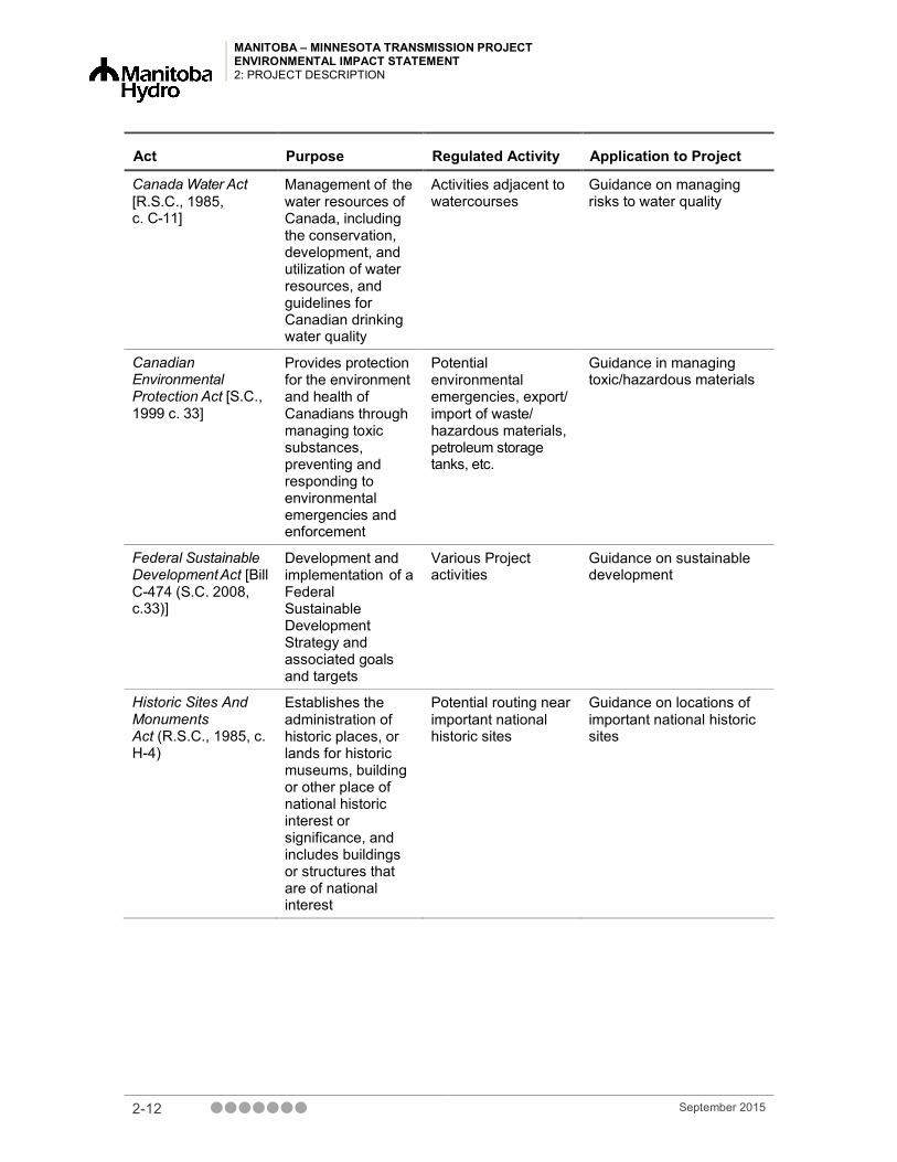
2.3.3.2 Other Requirements and Considerations Various environmental authorizations and notifications will be required under federal legislation to undertake activities ancillary to the construction and operation of the Project and some regulatory requirements provide guidance in dealing with Project activities. The various federal environmental statutes that were considered are listed in Table 2-2. Some of the key federal statutes that were considered were the Fisheries Act, the Navigation Protection Act, and the Species at Risk Act.
A number of watercourse crossings will be required for the Project. A Memorandum of Understanding (MOU) has been signed between Fisheries and Oceans Canada (DFO) and the NEB for transmission lines subject to the NEB Act 1985, c. N-7.The MOU transfers responsibilities for the assessment of transmission line watercourse crossings under the Fisheries
2-8 September 2015

MANITOBA – MINNESOTA TRANSMISSION PROJECT ENVIRONMENTAL IMPACT STATEMENT
2: PROJECT DESCRIPTION
Act (R.S.C., 1985, c. F-14) from DFO to the NEB. If the MOU is still in place during the approvals process and the NEB determines that an authorization or permit will be required, DFO shall be notified and will be responsible for issuing the authorization or permit.
The Navigation Protection Act, 1985 (R.S.C., 1985, c. N-22) has been in force since April 1, 2014, and replaces the previous Navigable Waters Protection Act. Legislative amendments were made to the Act to address public safety requirements and provide a refined regulatory review process for proponents and agents. While the new IPL that is part of the Project will cross the Red and Assiniboine rivers, which are designated as navigable under this Act, section 58.301 of the NEB Act renders the Navigation Protection Act inapplicable to IPLs. Pursuant to section 58.29 of the NEB Act, the NEB will consider effects ton public navigation at IPL crossings of navigable watercourses crossings and will make the decision as to whether to approve proposed crossings as part of its decision to authorize the IPL.
The Species at Risk Act (S.C. 2002, c. 29) is for the protection of species at risk. It applies to all extirpated, endangered and threatened plant and animal species listed in Schedule 1 of the Act as being at risk and to their critical habitat within all federal lands in Canada. Environment Canada is responsible for administering the Species at Risk Act for terrestrial species. Under the Species at Risk Act, the protection of aquatic species at risk falls under the jurisdiction of DFO. An authorization pursuant to section 73 of the Species at Risk Act might be required if it is determined that the Project will have an effect on a listed species, any part of such species’ critical habitat, or the residences of such critical species. For aquatic species, assuming the MOU between the NEB and DFO is still in place at this time, the NEB will assess potential effects of the Project on fish or fish habitat and aquatic species at risk. If the NEB determines that the Project could result in serious harm to fish or fish habitat, or adverse effects on species at risk, the NEB will notify DFO that a Fisheries Act authorization and Species at Risk Act permit might be required.
The Project region does not contain any national parks or national protected areas, areas of natural or historical significance to the nation, national historic sites, historic canals, historic museums, federal heritage buildings, historic places in Canada, federal archaeology, or Canadian heritage rivers. The Project does not cross any Indian Reserves. Explosives will be used for conductor splicing during conductor stringing in some areas and explosives will be stored at the Riel Converter Station magazine, which already has a permit for this activity.
September 2015 2-9

MANITOBA – MINNESOTA TRANSMISSION PROJECT ENVIRONMENTAL IMPACT STATEMENT 2: PROJECT DESCRIPTION
Table 2-2 Federal Environmental Statutes
Act Purpose Regulated Activity Application to Project
PERMITS APPLICABLE TO PROJECT
Explosives Act [R.S.C., 1985, c. E-17]
Addresses the manufacture, testing, sale, storage, and importation of explosives
Use of explosives in construction; will be stored at Riel Converter Station
Permit already obtained for Riel Converter Station
Migratory Birds Convention Act, 1994 [SC 1994, c. 22]
Protection of migratory birds in Canada and the United States, including damaging nest and harassment
Activities that have the potential to destroy or harass migratory birds and/or their nests
Permit obtained September 2, 2014 to conduct bird mortality monitoring. Intent is to avoid restricted activities by timing of construction
PERMITS NOT APLICABLE
Fisheries Act [R.S.C., 1985, c. F-14]
Protection of fisheries in Canada that are part of a commercial, recreational. or Aboriginal (CRA) fishery, or to fish that support such a fishery
Activities in or adjacent to waterbodies that have the potential to result in serious harm to CRA fisheries
Design of Project is intended to avoid serious harm to CRA fisheries
Navigation Protection Act [R.S.C., 1985, c. N-22]
Protection of designated navigable waters, as a result of the construction of any work, any dumping of fill or excavation of materials from the bed of a navigable river
Works crossing navigable waterbodies (Assiniboine and Red rivers)
Not applicable to IPLs as per section 58.301 of the National Energy Board Act
Canada Wildlife Act [R.S.C., 1985 c. W-9]
Conservation and management of the wildlife resources of Canada, including protection of endangered wildlife
Permit required for activities in Wildlife Areas
Proposed route avoids national parks and national protected areas
2-10 September 2015

MANITOBA – MINNESOTA TRANSMISSION PROJECT ENVIRONMENTAL IMPACT STATEMENT
2: PROJECT DESCRIPTION
Act Purpose Regulated Activity Application to Project
GUIDANCE ONLY
Transportation Of Dangerous Goods Act [S.C., 1992, c.34]
Promotes public safety (human life and health of property and the environment) in the transportation of dangerous goods, including qualifications, emergency response plans, etc.
Activities involving the transportation of dangerous/hazardous materials
Guidance on transportation of dangerous/hazardous materials
Species at Risk Act [S.C., 2002, c.29]
Protection to prevent wildlife species from becoming extirpated/ extinct, including the recovery of wildlife species that are extirpated, endangered or threatened as a result of human activity; and to manage species of special concern to prevent them from becoming endangered or threatened
Permit required for activities affecting a wildlife species at risk or any part of its critical habitat if it is scientific research and/or benefits the species or its critical habitat, or affecting the species is incidental to carrying out the activity
Guidance on avoidance of activities in areas with Species at Risk
Canada Transportation Act (S.C. 1996, c. 10)
Section regulates utility crossings of railways. Requirement for a crossing agreement to be negotiated between the proponent and the railway, which is filed with the Canada Transportation Agency.
Routing over railway crossings
Guidance requiring crossing agreement with the railway and the Canada Transportation Agency
September 2015 2-11
MANITOBA – MINNESOTA TRANSMISSION PROJECT ENVIRONMENTAL IMPACT STATEMENT 2: PROJECT DESCRIPTION
Act Purpose Regulated Activity Application to Project
Canada Water Act [R.S.C., 1985, c. C-11]
Management of the water resources of Canada, including the conservation, development, and utilization of water resources, and guidelines for Canadian drinking water quality
Activities adjacent to watercourses
Guidance on managing risks to water quality
Canadian Environmental Protection Act [S.C., 1999 c. 33]
Provides protection for the environment and health of Canadians through managing toxic substances, preventing and responding to environmental emergencies and enforcement
Potential environmental emergencies, export/ import of waste/ hazardous materials, petroleum storage tanks, etc.
Guidance in managing toxic/hazardous materials
Federal Sustainable Development Act [Bill C-474 (S.C. 2008, c.33)]
Development and implementation of a Federal Sustainable Development Strategy and associated goals and targets
Various Project activities
Guidance on sustainable development
Historic Sites And Monuments Act (R.S.C., 1985, c. H-4)
Establishes the administration of historic places, or lands for historic museums, building or other place of national historic interest or significance, and includes buildings or structures that are of national interest
Potential routing near important national historic sites
Guidance on locations of important national historic sites
2-12 September 2015

MANITOBA – MINNESOTA TRANSMISSION PROJECT ENVIRONMENTAL IMPACT STATEMENT
2: PROJECT DESCRIPTION
Act Purpose Regulated Activity Application to Project
Hazardous Products Act [R.S.C., 1985 c. H-3]
Prohibitions for the manufacturing, importing, selling, advertising, packaging, and labelling of consumer products, including those that are a danger to human health and safety
Use of hazardous products
Guidance on use of hazardous products
National Fire Code Of Canada, 1995
Provides fire safety inside and outside new and existing buildings, including spill control measures and storage of combustibles
Activities that have the potential to cause fires in/adjacent to buildings
Guidance on fire safety issues
Indian Act [R.S.C., 1985 c. I-5]
Protection of resources on Indian Reserves and protected lands
Potential routing through Aboriginal reserves
Avoidance of any First Nation Reserve lands
Radio Communication Act [.S.C., 1985, c. R-2]
Regulations addressing interference with radio signals
Technical requirements and standards for interference-causing equipment, such as transmission lines
Guidance on radio interference
Pest Control Products Act [S.C. 2002, c. 28]
Provides for the protection of human health and safety and the environment by regulating products used for the control of pests
Use of registered pest control products
Guidance on use of pest control products
September 2015 2-13

MANITOBA – MINNESOTA TRANSMISSION PROJECT ENVIRONMENTAL IMPACT STATEMENT 2: PROJECT DESCRIPTION
2.4 Project Component Overview Map 2-1 displays the various Project components and their location in Manitoba. The Project’s primary component is the construction of a 500 kV AC transmission line, named the Dorsey to Iron Range Transmission Line, with a line identification code of “D604I”. D604I will originate at the Dorsey Converter Station, located near Rosser, northwest of Winnipeg. The selection of Dorsey as the origin point for the Project was to provide two geographically separate points of interconnection for the two 500 kV import export lines in the Manitoba Hydro system to the United States for system reliability purposes. (The other 500 kV line (M602F) terminates at Riel Converter Station)., From Dorsey Converter Station the line will travel south around Winnipeg within the existing Southern Loop Transmission Corridor (SLTC) then head east within the existing Riel–Vivian Transmission Corridor (RVTC) to just south of Anola. From south of Anola, the transmission line will continue southeast in a New Right-of-Way (ROW), connecting to the Great Northern Transmission Line at the Manitoba-Minnesota border near Piney. The Great Northern Transmission Line, terminates at a new station called Iron Range Station adjacent to the existing Blackberry Station located northwest of Duluth, Minnesota. The Project also includes additions and modifications to associated existing stations at Dorsey, Riel and Glenboro South in Manitoba and modifications to the Riel IPL and Glenboro IPL. An overview of the Project components is presented below.
2.4.1 D604I 500 kV Transmission Line The transmission line will be located in both existing corridors as well as a new ROW. These will be described at a high level in this section.
2.4.1.1 Existing Transmission Corridors Manitoba Hydro has been planning, acquiring and obtaining easements for dedicated transmission corridors that contain multiple transmission lines since the early 1960s. The purpose has been to limit the effects of multiple independent ROWs in an area subject to extensive development surrounding the City of Winnipeg. The result is the establishment of a corridor that could house multiple transmission lines connecting stations around Winnipeg for the purposes of enhanced reliability and movement of power into and out of the Winnipeg centered grid. The Project will use two existing corridors: the Southern Loop Transmission Corridor, which traverses from Dorsey Converter Station to southeast Winnipeg, and the Riel–Vivian Transmission Corridor, which traverses from Riel Converter Station eastward (Map 2-2).
During the transmission line routing process (Chapter 5) the use of existing corridors was encouraged by stakeholders and the public. As a result, the existing Southern Loop and Riel–Vivian transmission corridors were used to route the Dorsey to Iron Range 500 kV Transmission Line (D604I) as a mitigative decision. This decision was made early in the routing process to avoid acquiring a new ROW within prime agricultural land and rural residential development areas
2-14 September 2015
MANITOBA – MINNESOTA TRANSMISSION PROJECT ENVIRONMENTAL IMPACT STATEMENT
2: PROJECT DESCRIPTION
where an existing planned transmission corridor has sufficient space to house the transmission line.
The tower spacing is estimated to be approximately 400 m to 500 m but may extend outside of this range, depending on topographic and geological features, proximity to existing infrastructure, soil conditions, environmental considerations and land use. Self-supporting lattice steel structures were chosen as part of the design to limit tower footprint and allow optimum use and placement of transmission lines within the corridor footprint.
The following section describes the Southern Loop and Riel–Vivian transmission corridors in more detail.
2.4.1.1.1 Southern Loop Transmission Corridor The Southern Loop Transmission Corridor (SLTC) is a utility corridor that extends from Dorsey Converter Station south and then east circumventing the City of Winnipeg and ending at the Riel Converter Station located on the east side of the City adjacent to the Red River Floodway (Map 2-2).
The existing Southern Loop Transmission Corridor is up to 245 m wide and is designed to accommodate multiple transmission lines necessary for system reliability and to meet future energy demands in southern Manitoba. There are currently two (2) 230 kV AC lines in this corridor, with additional transmission lines planned, including a 230 kV line from La Verendrye to St. Vital Station. With the addition of the Dorsey to Iron Range 500 kV Transmission Line (D604I), there will be three lines in this corridor; however, the corridor can house additional lines. Approximately 68 km of 500 kV AC transmission will be constructed within the Southern Loop Transmission Corridor between the Dorsey and Riel converter stations. At the Riel Converter Station, D604I will exit the SLTC and enter the Riel–Vivian Transmission Corridor.
2.4.1.1.2 Riel–Vivian Transmission Corridor The Riel–Vivian Transmission Corridor (RVTC) is a utility corridor that extends from the Riel Converter Station east to just south of Vivian, MB (Map 2-2). The existing Riel–Vivian Transmission Corridor is 177 m wide. Within this corridor there is currently one 500 kV AC transmission line (M602F - Riel to Forbes) and one 500 kv DC (Bipole III) line, which is under construction. With the addition of the Dorsey to Iron Range 500 kV Transmission Line (D604I), there will be three lines in this corridor.
Modifications to M602F Riel International Power Line
When two 500 kV transmission lines are in close proximity to each other there is increased risk to reliability due to extreme weather events or equipment failures affecting both transmission lines. The risk to reliability is exacerbated when these lines cross over each other. The overhead crossing location of D604I and M602F within the RVTC creates the potential for multiple lines to be out of service if the upper line were to fail and fall on the lower line. In order to mitigate this risk, the existing Riel IPL (M602F) and future 500 kV transmission lines (D604I and Bipole III)
September 2015 2-15
MANITOBA – MINNESOTA TRANSMISSION PROJECT ENVIRONMENTAL IMPACT STATEMENT 2: PROJECT DESCRIPTION
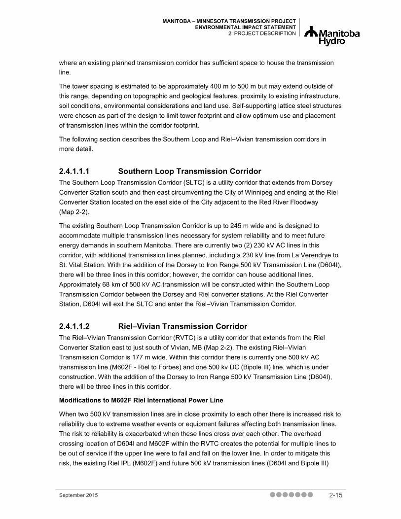
have to be arranged to avoid or limit the effects of crossing each other. To facilitate this, a segment of the existing M602F transmission line from Riel to PTH 12 (approximately 24 km) will be used as a portion of the new D604I transmission line. To facilitate this exchange, M602F will be moved from its current location and be built on new structures over the same 24 km distance just north of its current location within the transmission corridor. At the point D604I exits the RVTC to the south on a new ROW, M602F will route back and connect to its existing structures, as shown in Figure 2-1 and Figure 2-2.
Figure 2-1 Western Modifications to M602F using a portion of new tower construction for its line
2-16 September 2015

MANITOBA – MINNESOTA TRANSMISSION PROJECT ENVIRONMENTAL IMPACT STATEMENT
2: PROJECT DESCRIPTION
Figure 2-2 Eastern Modifications to M602F using a portion of new tower construction for its line
2.4.1.2 New Right-of-Way From the Existing Transmission Corridor (Existing Corridor), as described above, south of Anola, MB, the D604I transmission line will proceed southeast within a New ROW for approximately 121 km (Map 2-3). The New ROW as designed, passes through a portion of southeast Manitoba that has a variety of land uses, including agriculture, rural residential and Crown land.
The ROW width requirement will be approximately 80 m for self-supporting towers and 100 m for guyed towers. The typical 500 kV structure height is expected to range between 50 and 60 m, depending on terrain conditions and environmental sensitivities. The tower spacing is estimated to be approximately 400 m to 500 m but may extend outside of this range, depending on topographic and geological features, proximity to existing infrastructure, soil conditions, environmental considerations and land use. In cultivated agricultural areas, this transmission line will be constructed primarily of self-supporting lattice steel structures to mitigate effects on both agricultural and rural residential land uses through reduced tower footprints and ROW width. In non-agricultural areas, the transmission line will be constructed primarily of guyed lattice steel structures to mitigate effects on tower stability caused by saturated soils, along with financial savings associated with reduced materials and construction costs.
September 2015 2-17

MANITOBA – MINNESOTA TRANSMISSION PROJECT ENVIRONMENTAL IMPACT STATEMENT 2: PROJECT DESCRIPTION
2.4.2 Modifications/Additions to Existing Stations
2.4.2.1 Dorsey Converter Station To connect and integrate the D604I 500 kV AC transmission line to the existing electrical network, modifications and additions will be required at the existing Dorsey Converter Station northwest of Winnipeg in Rosser, MB. The station modifications include the addition of circuit breakers to permit line termination of D604I as well as reactors. The addition of reactors will act as a safety mechanism to reduce the D604I line voltage at Dorsey Converter Station in the event that a breaker is open at Dorsey Converter Station.
In order to accommodate the new equipment and line termination, the station site will also need to be modified. The station fence line will be expanded to the west for a total of 15,902 m2 on Manitoba Hydro-owned property. Map 2-4 outlines the planned station expansion.
Modifications at Dorsey Converter Station are expected to begin in spring 2018 and be completed in fall 2019.
2.4.2.2 Riel Converter Station The Riel Converter Station is located east of the Red River Floodway and north of the City of Winnipeg’s Deacon Water Supply Reservoir in the Rural Municipality of Springfield. The site has recently been developed in accordance with the previously approved and licensed Riel Reliability Improvement Initiative and is now undergoing further development under the previously approved and licensed Bipole III Transmission Project (Map 2-5) (Manitoba Hydro 2011).
There will be additional electrical construction at the Riel Converter Station as part of the Project. All additions will be contained within the current fenced area of the 500 kV switchyard portion of the Riel Converter Station. The additions primarily include three single-phase 400 MVA autotransformers and associated equipment. The additions of the autotransformers at the Riel Converter Station provide sufficient capacity to allow the increase in firm export capability to the US, especially in the event that one of the Dorsey or Riel 500 kV autotransformers is out of service.
Riel Converter Station construction is expected to begin in summer 2017, with a completion date of fall 2019.
2.4.2.3 Glenboro South Station Manitoba Hydro’s Glenboro South Station is located 1.5 km south of the junction of Provincial Trunk Highway (PTH) 2 and PTH 5 in an agricultural dominated landscape (location coordinates 49°32'18"N, 99°17'02" W). This station contains the termination facilities of the Glenboro International Power Line that transmits power from Glenboro South Station to Rugby station via the 230 kV AC Glenboro-Rugby International Transmission Line. The principal electrical
2-18 September 2015

MANITOBA – MINNESOTA TRANSMISSION PROJECT ENVIRONMENTAL IMPACT STATEMENT
2: PROJECT DESCRIPTION
component additions associated with the MMTP are two (2) 300 MVA phase shifting transformers connected in series with the Glenboro to Rugby transmission line.
A phase shifting transformer is a special type of transformer that controls the flow of electricity in a transmission line. With the addition of the Dorsey to Iron Range 500 kV Transmission Line (D604I), there will be network changes that result in additional loop flows (power flows) that emanate from the U.S. grid. This will flow into Manitoba in the west and back into the U.S. grid in the east through the Manitoba Hydro system. The phase shifting transformer (PST) is able to prevent undesirable power flow on the Glenboro to Rugby transmission line or neighbouring transmission lines by adjusting its power setpoint and is used for electrical congestion management purposes. The PST is an economic alternative to retensioning or constructing new transmission to eliminate congestion. To accommodate the new phase shifting transformers, the site will need to be modified. The Glenboro South Station fence line will be expanded 130 m × 91 m east of the existing 230 kV switchyard on Manitoba Hydro owned property. In addition to the above, modifications to (3) three transmission lines (S53G, G37C,and G82R) will be required. See Map 2-6 of the proposed expansion and relocation.
Glenboro South Station construction is expected to begin in winter 2019, with a completion date of fall 2019.
2.5 Alternative Project Designs Voltage of new international power line
The option of a 230 kV transmission line was initially considered in the transmission studies that were performed pursuant to Manitoba Hydro’s Open Access Transmission Tariff (OATT) (Manitoba Hydro 2012). The results of the System Impact Study conducted for the Project indicated that “… either a 500 kV transmission line or a 230 kV transmission line from Riel to the Manitoba U.S. border is needed in Manitoba for accommodating all or parts of the transmission service requests…”. While the early stages of the ensuing Facilities Study continued to analyze the 230 kV option, Manitoba Hydro chose to eliminate this option prior to completion of the Facilities Study, as a 230 kV transmission line would only provide the transmission capacity required for two transmission service requests. In addition, during the course of the NFAT review, it became apparent that a 230 kV interconnection with the United States was not a realistic option from a business perspective, as Minnesota Power took the position in its Certificate of Need filing (Section 7.4.2.1, pg. 77) that a 230 kV interconnection “would not serve the long-term needs of the region and would not prove to be cost-effective for customers or environmentally preferable over the long term” (Minnesota Power, 2013). As indicated previously, selection of the 500 kV option was also supported by the Provincial Needs For and Alternatives To (NFAT) review.
Termination Points for Dorsey IPL
The Preliminary Group Facilities Study outlined four different alternatives for a 500 kV line to meet the capacity requirements of the transmission service requests (Manitoba Hydro 2013c). Two of the alternatives proposed a termination point in the U.S. at the Iron Range Station in
September 2015 2-19

MANITOBA – MINNESOTA TRANSMISSION PROJECT ENVIRONMENTAL IMPACT STATEMENT 2: PROJECT DESCRIPTION
Minnesota and the other two alternatives proposed a U.S. termination point in Fargo, North Dakota at the Bison Station. Manitoba Hydro chose to eliminate the options related to a Fargo termination point based on the lack of a U.S. party willing to fund such a configuration. Based on the power purchase agreements with Minnesota Power, Minnesota Power was willing to contribute to the funding of the transmission line terminating at a station within its service territory.
Double Circuit and Underground Options
There are several technical alternatives that are able to achieve the Manitoba to U.S. transfer capability increase that was requested under the OATT. Overhead construction of a single circuit 500 kV or a double-circuit 345 kV transmission line are two viable options. Double circuit 345 kV was analyzed in some detail and found to perform technically similar to a single circuit 500 kV line. However, there was a cost premium of 25% to build a double-circuit 345 kV line, which could not be justified.
Lower voltages, such as 230 kV, were not considered economically feasible given that at least two double-circuit 230 kV lines would be required plus an intermediate substation.
A 500 kV AC underground cable was deemed not a feasible alternative. There is only limited experience in the world at lengths of less than 20 km for urban supply applications. Cable joints pose a reliability concern given that there is no experience available for high voltage cables installed with winter ambient temperatures less than zero degrees Celsius. Failure rates and repair times are expected to be much higher than an overhead line. The cost of underground cable is expected to be at least 10 times more expensive than comparable overhead transmission.
Towers
Steel lattice towers were chosen rather than the alternative tubular structures. While steel lattice towers require larger ROWs than tubular towers, there are several advantages. Steel lattice towers allow for longer span lengths, thereby reducing the number of obstacles that land owners may need to avoid when operating agricultural equipment. An increased span length reduces the total number of towers required, thereby reducing the total area of tower footprint that will be disturbed during construction of the Project. The use of steel lattice towers also reduces the vertical spread of the IPL, which, in turn, reduces avian collision zones. These three attributes provide mitigation against potential adverse effects of the Project. In addition, the construction of steel lattice towers creates nesting platforms for birds of prey, thus generating a positive effect on the environment.
Self-supporting towers were chosen over guyed towers in cultivated areas to mitigate adverse effects by reducing tower footprints and the amount of land required for an ROW. Guyed towers were chosen for other locations due to lower costs and for tower stability in saturated soils.
2-20 September 2015

MANITOBA – MINNESOTA TRANSMISSION PROJECT ENVIRONMENTAL IMPACT STATEMENT
2: PROJECT DESCRIPTION
Riel IPL Relocation
The decision to relocate a segment of the Riel IPL, rather than the alternative of constructing two 500 kV line crossover structures, was based primarily on reliability considerations. A crossover creates the risk of an outage to two IPLs arising from a conductor or tower failure. In addition, crossovers are a more expensive alternative to design and construct.
2.6 Project Location This section provides a description of the transmission line route along with intersecting existing infrastructure it crosses from its origin at Dorsey Converter Station to the border crossing location south of Piney, MB. The Map Folio located in the Executive Volume should be viewed in conjunction with the description below.
2.6.1 Southern Loop Transmission Corridor Dorsey Converter Station to La Verendrye
Starting from the Dorsey Converter Station at geographic coordinates of approximate latitude of 49.9882 degrees and longitude of -97.4318 degrees, D604I heads south along the Southern Loop Transmission Corridor (SLTC) (Map 2-2). Use of the existing SLTC to traverse from Dorsey Converter Station to southeast Winnipeg will avoid the need to acquire a new ROW within prime agricultural land and rural residential development areas. This mitigative decision to design D604I within the existing Southern Loop Transmission Corridor was made early in the routing process.
As described below, D604I will need to cross a variety of infrastructure in the SLTC due to physical constraints. In the instance of existing transmission lines, it will cross two 230 kV double circuit transmission lines associated with the Dorsey Converter Station (D11Y & D15Y and D14S & D55Y) as well as one 230 kV single circuit and two 115 kV double-circuit transmission lines associated with the La Verendrye Station (Y51L, YM31, Y51L, YT10) (Figure 2-3). D604I will also need to cross one double circuit 115 kV transmission (VT63, VJ50) and one proposed single circuit 230 kV transmission line (V95L).
September 2015 2-21

MANITOBA – MINNESOTA TRANSMISSION PROJECT ENVIRONMENTAL IMPACT STATEMENT 2: PROJECT DESCRIPTION
Figure 2-3 Southern Loop Transmission Corridor – Transmission Line Crossovers
While this could create the risk for multiple lines to be out of service should the lines fall on each other, the integrated nature of the transmission system in the Winnipeg area mitigates this risk. D604I will be crossing more than two underlying circuits at three locations along the SLTC. For comparison purposes, D603M crosses more than two underlying circuits at four locations along the northern loop transmission corridor between Dorsey and Riel. The reliability of this design approach has been proven, as there have been no mechanical failures at the crossover locations since the line was placed in service in 1980.
D604I exits the west side of Dorsey Converter Station switchyard, and then heads south along the Southern Loop Transmission Corridor (SLTC). Just south of Dorsey Converter Station, it crosses PR 221 then two double circuit transmission lines (D11Y & D15Y as well as D14S & D55Y) also exiting Dorsey Converter Station. It continues south through agricultural land, passing along the west side of an intensive hog operation, along SLTC for approximately 12 km until it crosses the TransCanada Highway (TCH), just west of the town of Headingly. South of the TCH, the route crosses the Assiniboine River. South of the Assiniboine River, the route continues south along the SLTC through agricultural land for approximately 6.5 km, crossing over PR 241, PR 427 and the Canadian Pacific Railway. The route then crosses over 2 double circuit transmission lines (D11Y & D15Y and D14S & D55Y) then turns east paralleling these lines. The route continues east through agricultural land crossing PR 334 heading to La Verendrye Station.
Continuing south from the La Verendrye Station connection, one 230 kV transmission line (Y51L) and two 115 kV transmission lines (YM31 / YT10) occupy the corridor.
La Verendrye to Deacon’s Reservoir
At La Verendrye Station, the transmission line turns south, crossing three transmission lines (YM31, Y51L, YT10) connected to La Verendrye Station. In May 2014, Manitoba Hydro submitted an Environment Act proposal to build a future 230 kV transmission line within the Southern Loop Transmission Corridor from La Verendrye Station east to St. Vital Station. This proposal has not yet been approved by regulators.
2-22 September 2015
MANITOBA – MINNESOTA TRANSMISSION PROJECT ENVIRONMENTAL IMPACT STATEMENT
2: PROJECT DESCRIPTION
From La Verendrye Station the route heads south along the SLTC through agricultural land and crosses PTH 2 then heads east crossing YF11 and PTH 3. The route continues east through agricultural land crossing PR 330 and PTH 75, heads northeast, crosses through Duff Roblin Provincial Park then over the Red River just north of the Red River Floodway inlet. East of the Red River, the route crosses over the floodway, then over PR 200 and parallels the floodway on the south side for approximately 14 km, crossing over PR 300 twice, then the Seine River just south of where it enters the floodway. The route then crosses PTH 59, one double circuit 115 kV transmission line (VT63, VJ50) and one proposed single circuit 230 kV transmission line (V95L). In May 2014, Manitoba Hydro submitted an Environment Act proposal to build a future 230 kV transmission line (V95L) from St. Vital Station to Lettelier Station (Manitoba Hydro 2014). This proposal has not yet been approved by regulators. The route continues to parallel the floodway as it turns north crossing the TransCanada Highway. The route travels north for approximately 3 km, passing along the west side of Deacon Reservoir and the City of Winnipeg’s Water Treatment Plant south of the Riel Converter Station (Map 2-2).
2.6.2 Riel–Vivian Transmission Corridor After the transmission line route leaves the SLTC and heads east within the Riel–Vivian Transmission Corridor (RVTC) along the northern end of Deacon’s Reservoir along the south side of Riel Converter Station. Within the RVTC there is one existing 500 kV ac transmission line (M602F) and one 500 kV DC transmission line (Bipole III) under construction. In an effort to mitigate the potential risk of losing both the M602F and D604I 500 kV transmission lines, a potential crossover was eliminated. To facilitate this, a portion of the structures and conductors used for the existing M602F from Riel to PTH 12 (approximately 24 km) will become a portion of the new D604I transmission line. M602F would be transferred to new structures and conductors over the same 24 km distance just north of its current location within the transmission corridor. At the location that D604I exits the transmission corridor to the south along the new ROW, M602F will reconnect with the existing structures and conductors (Map 2-2).
2.6.3 Transmission Line within New Right-of-Way
As indicated previously, a new ROW is required for the development south of the Existing Corridor to the U.S. border. The ROW width varies throughout its 121 km length from 80 m when self-supporting steel lattice towers are used to 100 m when guyed steel lattice towers are used. Map 2-7 illustrates where each ROW width is used along its length.
South of Anola, MB and east of PTH 12 the route turns south, entering a new ROW through agricultural land. The route crosses the Greater Winnipeg Water District (GWWD) aqueduct and the GWWD Rail Line. At this point, the landscape starts to change from primarily agricultural land to a mix of pasture land and forested area. Land ownership becomes a mix of Crown and private land. The route parallels the existing 230 kV Transmission line (R49R) from Ridgeway Station to
September 2015 2-23

MANITOBA – MINNESOTA TRANSMISSION PROJECT ENVIRONMENTAL IMPACT STATEMENT 2: PROJECT DESCRIPTION
Richer South for just over 4 km. The landscape has changed to a mix of pasture and forested area. The route continues southeast then turns south crossing over R49R then paralleling it on the west side, in a southeasterly direction for approximately 8 km. The route runs east of Cottonwood and Oakwood golf courses and crosses the TransCanada Highway for the third time.
The transmission line route separates from R49R at Richer South Station and turns southwest. It runs through several parcels of proposed protected area at Richer South Station. The route crosses PR 302 then heads generally south for approximately 37 km. The route runs along the eastern edge of La Verendrye Golf Course then crosses PR 210 and the Canadian National Railway. The route turns southeast running adjacent to the western boundary of the Watson P. Davidson Wildlife Management Area (WMA). At the south end of the WMA, the route runs southeast passing through the Caliento Bog. The route stays west of the Spur Woods WMA then runs east southeast through mixed pasture and natural areas, then turns southeast running west of Piney Creek and then crosses over Piney Creek and meets the international border just east of Piney Creek. The route meets the international border southwest of Piney Creek at geographic coordinates of approximately 49.0000 degrees latitude and -95.9140 degrees longitude.
2.7 Engagement Purpose and Goals Engagement with the public, stakeholder groups, First Nations and Metis is an important aspect of Manitoba Hydro transmission line projects. The engagement processes aims to inform these groups of Manitoba Hydro’s projects and allows them to become involved and provide feedback in the routing and environmental assessment work being undertaken.
The goals developed for the engagement processes for this Project were to:
• share Project information
• obtain feedback for use in the transmission line routing and environmental assessment process
• gather and understand local interests and concerns
• integrate interests and concerns into the routing and assessment processes
• review potential mitigation measures
To achieve these goals, Manitoba Hydro developed a process that included:
• involving the public throughout transmission line routing and environmental assessment stages
• providing clear, timely, and relevant information and responses
• delivering a public engagement process that is adaptive and inclusive
2-24 September 2015

MANITOBA – MINNESOTA TRANSMISSION PROJECT ENVIRONMENTAL IMPACT STATEMENT
2: PROJECT DESCRIPTION
• informing the public as to how their feedback influenced the Project
• documenting and reporting on feedback received
The public engagement process (PEP) aimed to be inclusive, adaptive, comprehensive and responsive to participant’s needs and feedback.
2.7.1 Public Engagement The PEP was developed in consideration of the Canadian Environmental Assessment Act (CEAA 2012) and applicable regulations and guidelines, the guidelines for Environment Act Proposals (MCWS 2014) under The Environment Act (Manitoba), and the NEB Electricity Filing Manual (Chapter 5) (NEB 2015). Review of best practices and guidelines from the International Association of Public Participation and the International Association of Impact Assessment was also completed to assist with development of the PEP.
Manitoba Hydro undertook several rounds of engagement for the Project, beginning in summer, 2013. Throughout the process, Manitoba Hydro presented the Project to share information and created opportunities to collect feedback from the public and stakeholder groups. Feedback and concerns raised by PEP participants as well as site-specific information were provided to discipline specialists in order to inform their environmental assessment of the Project and to assist in the transmission line routing process.
The methods Manitoba Hydro selected provided various opportunities for feedback to be collected throughout the process. These included numerous notification methods to reach a wide variety of people throughout Manitoba. Engagement activities such as public open houses, meetings, landowner information centres, a toll free information line and a Project email address allowed interested individuals to participate in the PEP. These efforts assisted Manitoba Hydro in obtaining public feedback regarding the transmission line routing process, mitigation methods and adapting the process as appropriate throughout all rounds of engagement.
The PEP will continue throughout the regulatory, construction, and operation and maintenance phases of the Project to continue sharing information and addressing questions and concerns.
2.7.2 First Nation and Metis Engagement The First Nation and Metis Engagement Process was designed using guidance from the NEB Electricity Filing Manual (NEB 2015), the CEAA Public Participation Guide (CEAA 2013), an understanding of the International Association of Public Participations spectrum of Public Participation, recent feedback and commentary from provincial regulators, as well as past project experience. The design and methods of the First Nation and Metis Engagement Process were intended to involve the communities throughout all stages of pre-Project activities, transmission line routing, environmental assessment and the regulatory review process.
September 2015 2-25

MANITOBA – MINNESOTA TRANSMISSION PROJECT ENVIRONMENTAL IMPACT STATEMENT 2: PROJECT DESCRIPTION
In August 2013, Manitoba Hydro sent an initial letter of invitation to First Nations, the MMF and Aboriginal Organizations. Manitoba Hydro followed up with phone calls or emails to make sure the initial letters were received and to schedule and confirm leadership meetings or open houses/information sessions. During Round 1 engagement, Manitoba Hydro provided First Nations, the MMF and Aboriginal organizations the opportunity to provide feedback to assist in the evaluation of the alternative routes presented, and the identification of a preferred border crossing for the Project. In Round 2, Manitoba Hydro presented the preferred border crossing with alternative routes to First Nations, the MMF and Aboriginal organizations, with opportunity to share concerns and perspectives. In early 2015, during Round 3, Manitoba Hydro presented the preferred route for the transmission line based on the environmental assessment and input received during previous rounds. Manitoba Hydro plans to continue engagement activities throughout the regulatory process, and the construction and operation and maintenance phases of the Project.
Further details regarding the First Nation and Metis engagement process are provided in Chapter 4.
2.8 Design Philosophy The description of the transmission line components of the Project is based on current design and will comply with Manitoba Hydro standards and guidelines with respect to design and construction, operation and maintenance. Should the design change and result in an environmental effect, effects will be reviewed. Key standards and guidelines include:
• MH-TLD-GL001 – Determination of Transmission Line Right-of-Way and Clearing Requirements Rev1 2007
• Station Design Department Standard – Electrical Clearances - 2006
Project development will also adhere to applicable North American Electric Reliability Corporation/Midwest Reliability Organization standards that have been adopted under Manitoba regulations and applicable Manitoba Hydro standards and criteria. Subject to approval requirements, details of final design may vary from the current design based on field conditions and contract requirements.
Design of the D604I 500 kV AC transmission line and along with modifications to existing transmission lines will be subject to two Canadian Standards Association (CSA) design standards:
• CSA C22.3 No. 1-10 “Overhead Systems” standard 2010a; and
• CAN/CSA-C22.3 No. 60826-2010 “Design criteria of overhead transmission lines” standard 2010b.
2-26 September 2015

MANITOBA – MINNESOTA TRANSMISSION PROJECT ENVIRONMENTAL IMPACT STATEMENT
2: PROJECT DESCRIPTION
The CSA C22.3 No. 1-10 “Overhead Systems” standard will be applied to determine all electrical and safety clearances. Manitoba Hydro designs its transmission lines to meet or exceed this standard. To further mitigate existing and future large equipment use in agricultural crop lands, clearance will be a minimum of approximately 13 m to allow safe operation of machinery under the line. Table 2-3 illustrates the standard clearances and Manitoba Hydro’s designed clearances for this Project.
Table 2-3 Overhead Systems Clearance Requirements
Feature
CSA 22.3 No. 1-10 “Overhead Systems”
Requirements for 500 kV
MH Design for Overhead Systems Requirements for
500 kV
Minimum Vertical Clearance2 (m)
Minimum Vertical Clearance2 (m)
Over or alongside farmland 9.9 13
Over roads or highways 15.625 15.625
Over pipelines1 9.9 9.9
Over driveways 15.4 15.4
Over walkways or ground normally accessible only to pedestrians snowmobiles, and personal use all-terrain vehicles
6.3 6.3
Over waterways1 Dependent on water body classification
Over rail1 10.7 10.7 NOTES: 1 Approvals for rail, pipeline, and waterway crossings will be obtained as needed. 2 Minimum vertical clearance is calculated based on 3000A, corresponding to a 100°C conductor temperature, or under
weather loading, whichever results in the least clearance.
The CAN/CSA-C22.3 No. 60826-10 “Design criteria of overhead transmission lines” standard will be used for structural and mechanical design, applying design loads based on a 150-year return period, in accordance with the reliability based design method. The 150-year return standard is consistent with CSA standards for transmission lines over 230 kV in the Reliability Level II category, which, in turn, reflect recommendations of International Electrotechnical Commission.
September 2015 2-27

MANITOBA – MINNESOTA TRANSMISSION PROJECT ENVIRONMENTAL IMPACT STATEMENT 2: PROJECT DESCRIPTION
2.9 Transmission Line Design and Mitigation Details
Manitoba Hydro begins mitigating the potential effects of its transmission projects at the design stage of a project, starting with transmission line routing, engineering details such as tower type, span and location, and ROW width. This section explains how design considerations have played an important role in mitigating project effects.
2.9.1 Transmission Line Routing As previously described, the transmission line will be located in existing corridors and a new ROW. The Final Preferred Route for the transmission line was determined using an approach based on the EPRI-GTC Routing Methodology (EPRI-GTC 2006). The methodology is a quantitative, computer-based methodology developed by the Electric Power Research Institute (EPRI) and Georgia Transmission Corporation (GTC) for use as a tool in evaluating the suitability of an area for locating new overhead transmission lines. Based on analysis, macro corridors are created which define the route planning area. Using more detailed information, alternative corridors are then developed. Within the alternative corridors, alternative routes are identified and analyzed. Employing increasingly detailed data focused on areas of greater suitability, the methodology allows Manitoba Hydro to take into consideration large amounts of information and to quantitatively consider stakeholder input during project development.
Routing is a primary means to mitigate effects on people and the environment. Feedback received through the engagement and environmental assessment processes was incorporated into routing decisions. Environmental and socio-economic routing criteria were considered in the transmission line routing process. Routing criteria included proximity to residential concentrations, major developments, conservation lands, resource uses, riparian areas, and existing ROWs. Routing also considered sensitive sites—locations, features, areas, activities or facilities identified by discipline specialists, First Nations, Metis or through the public engagement program to be ecologically, socially, economically or culturally important or sensitive to disturbance in relation to Project infrastructure. Sensitive sites could include valued and protected vegetation, wildlife and habitats, cultural sites (e.g., heritage/archaeological and spiritual sites), unique terrain features, erosion- and compaction-prone soils, and other important locations where route avoidance would be an effective means of mitigation. Additional details on route selection are provided in Chapter 5.
2.9.2 Tower Type and Span Manitoba Hydro has chosen steel lattice structure types for this Project, and two types of steel lattice structures will be used for the Project. A typical self-supporting steel lattice 500 kV structure is illustrated in Figure 2-4. A typical guyed steel lattice 500 kV structure is illustrated in Figure 2-5.
2-28 September 2015

MANITOBA – MINNESOTA TRANSMISSION PROJECT ENVIRONMENTAL IMPACT STATEMENT
2: PROJECT DESCRIPTION
Figure 2-4 Typical 500 kV Self-Supporting Steel Lattice Structure
September 2015 2-29

MANITOBA – MINNESOTA TRANSMISSION PROJECT ENVIRONMENTAL IMPACT STATEMENT 2: PROJECT DESCRIPTION
Figure 2-5 Typical 500 kV Guyed Steel Lattice Structure
2-30 September 2015

MANITOBA – MINNESOTA TRANSMISSION PROJECT ENVIRONMENTAL IMPACT STATEMENT
2: PROJECT DESCRIPTION
As designed, D604I will use a combination of new tower construction and existing towers. M602F will be modified to use a portion of new tower construction for its line as shown in Figure 2-1 and Figure 2-2.
Three specific types of tower structures will be used for the new tower construction of the D604I and portions of the M602F transmission line:
• tangent towers – installed in straight sections of line;
• angle towers – located where there is a change in route direction and are subject to additional longitudinal loads arising from the tension of the conductors; and
• dead-end towers - towers at the terminations of the line subject to loads arising from the unbalanced effect of conductor tension on one side of the structure.
Angle and dead-end tower types are designed for more complex loading conditions that typically require greater structural strength and larger footprints than required for tangent towers. These stronger towers are a design consideration to mitigate the effects of extreme weather events capable of causing multiple tower failures and for deflecting the transmission line.
Special crossing structures will be designed to mitigate overhead clearance issues and riparian setbacks necessary in specific circumstances (e.g., long span crossings of major rivers or roadways, or crossings of other transmission lines). Such structures will typically require greater height, greater strength and heavier construction, but will otherwise be similar to other structures.
2.9.2.1 Structures within Existing Transmission Corridors
Southern Loop Transmission Corridor For straight line sections in the Southern Loop Transmission Corridor (SLTC), tangent self-supporting lattice steel structures (Figure 2-4) will be used to limit tower footprints and provide space for potential future transmission lines. Tower spans will generally be between 300 m and 500 m but may be outside of this range depending on topographic and geological features, proximity to existing infrastructure, soil conditions, environmental considerations, and land use.
A summary of tower structure types to be used in the SLTC is provided in Table 2-4.
September 2015 2-31

MANITOBA – MINNESOTA TRANSMISSION PROJECT ENVIRONMENTAL IMPACT STATEMENT 2: PROJECT DESCRIPTION
Table 2-4 Southern Loop Transmission Corridor Tower Structure Types
Tower Structure Type
Figure (approximate)
Tower Footprint1
(approximate)
Tower Height1
(approximate)
Crossarm Width
(approximate)
Estimated Quantities2
(approximate)
Tangent self-supporting lattice steel
Figure 2-4 10 × 10 m 50 m 17 m 160
Angle self-supporting lattice steel
Figure 2-4 15 × 15 m 55 m 17 m 19
NOTES: 1 Based on basic tower without extension 2 Estimated quantities based on estimated 400 m average span and a section length of approximately 70 km
2.9.2.1.1 Riel–Vivian Transmission Corridor Within the Riel–Vivian Transmission Corridor (RVTC) from Riel Converter Station to PTH 12 the new D604I transmission line will use the existing towers, insulators and conductors currently in use on the Riel to Forbes (M602F) transmission Line. Table 2-5 describes the existing structures D604I will use within the RVTC.
Table 2-5 Riel–Vivian Transmission Corridor Existing Tower Structure Types
Tower Structure Type
Figure Tower Footprint1
Tower Height1
Crossarm Width
Estimated Quantities
Tangent self-supporting lattice steel
Figure 2-4 10 × 10 m 50 m 13.4 m 59
Angle self-supporting lattice steel
Figure 2-4 15 × 15 m 43 m 14.4 m 2
NOTE: 1 Based on basic tower without extension
Within the RVTC from Riel Converter Station to PTH 12 (approximately 24 km) the M602F transmission line will be constructed on new structures, as described in the Table 2-6 the same type as described in the SLTC above.
2-32 September 2015

MANITOBA – MINNESOTA TRANSMISSION PROJECT ENVIRONMENTAL IMPACT STATEMENT
2: PROJECT DESCRIPTION
Table 2-6 Riel–Vivian Transmission Corridor New Tower Structure Types
Tower Structure Type
Figure (approximate)
Tower Footprint1
(approximate)
Tower Height1
(approximate)
Crossarm Width
(approximate)
Estimated Quantities2
(approximate)
Tangent self-supporting lattice steel
Figure 2-4 10 × 10 m 50 m 17 m 65
Angle self-supporting lattice steel
Figure 2-4 15 × 15 m 55 m 17 m 2
NOTES: 1 Based on basic tower without extension 2 Estimated quantities based on estimated 400 m average span and a section length of approximately 24 km
2.9.2.2 Structures within New Right-of-Way For straight line sections on the new ROW being developed south of the Existing Corridor, a mixture of tangent self-supporting lattice steel structures (60 km) and tangent guyed lattice steel structures (61 km) will be used. In the more intensively developed agricultural and rural residential areas, tangent self-supporting lattice steel structures will be used to limit the potential effects on farming activities and adjacent residential properties by reducing the tower footprint and ROW width. In non-agricultural areas, the transmission line will be constructed primarily of guyed lattice steel structures.
Tower spans will be approximately 400 m apart. The typical structure height is expected to range between 50 and 60 m, depending on terrain conditions and environmental sensitivities.
A summary of tower structure types to be used in the New ROW section is provided in Table 2-7. Note that all values are estimates based on current design and are subject to change.
September 2015 2-33

MANITOBA – MINNESOTA TRANSMISSION PROJECT ENVIRONMENTAL IMPACT STATEMENT 2: PROJECT DESCRIPTION
Table 2-7 New Right-of-Way from Existing Corridor to U.S. Border
Tower Structure Type
Figure (approximate)
Tower Footprint1
(approximate)
Tower Height1
(approximate)
Crossarm Width
(approximate)
Estimated Quantities2
(approximate)
Tangent self-supporting lattice steel
Figure 2-4 10 × 10 m 50 m 17 m 117
Angle self-supporting lattice steel
Figure 2-4 15 × 15 m 55 m 17 m 33
Tangent guyed lattice steel
Figure 2-5 100 × 100 m 55 m 17 m 126
Angle guyed lattice steel
Figure 2-5 100 × 100 m 55 m 17 m 4
NOTES: 1 Based on basic tower without extension 2 Estimated quantities not available as route has not been finalized
2.9.3 Conductors The transmission towers will support one set of triple-conductor bundles for each of the three phases, suspended by insulators (Figure 2-6).
2-34 September 2015

MANITOBA – MINNESOTA TRANSMISSION PROJECT ENVIRONMENTAL IMPACT STATEMENT
2: PROJECT DESCRIPTION
Figure 2-6 Triple-conductor bundles for each of the three phases, suspended by insulators
Each of the nine sub-conductors will be aluminum conductor steel reinforced (ACSR) type material. Current key conductor specifications are outlined in Table 2-8.
Table 2-8 Current Phase Conductor Specifications
Parameter Current Design Specification
Number of Phase Sub-Conductors Each phase will be comprised of a triple sub-conductor bundle.
Phase Sub-Conductor Type 1192.55 MCM (thousand circular mils) 45/7 aluminum to steel stranding ACSR, code name “Bunting”
Phase Sub-Conductor Diameter 33 mm
Phase Sub-Conductor Bundle spacing 460 mm
Steel Shield Wire Type/Diameter Size 10 (11 mm) Steel - 7 Strand Grade 1300
September 2015 2-35
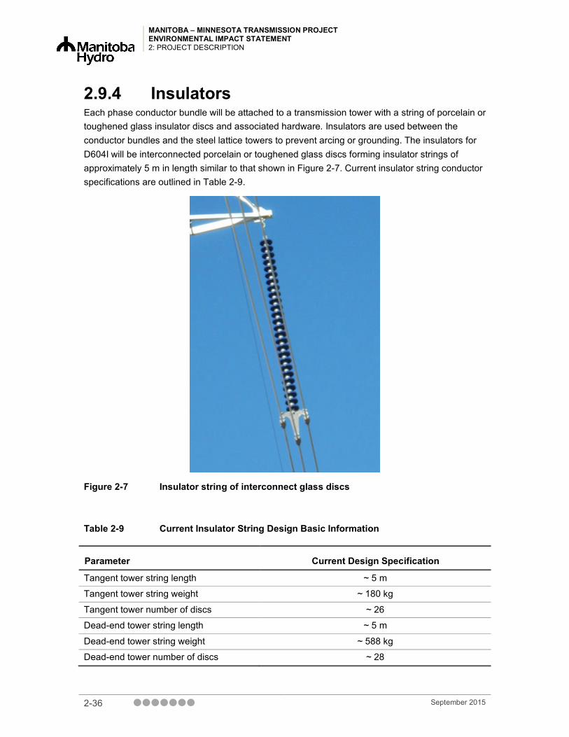
MANITOBA – MINNESOTA TRANSMISSION PROJECT ENVIRONMENTAL IMPACT STATEMENT 2: PROJECT DESCRIPTION
2.9.4 Insulators Each phase conductor bundle will be attached to a transmission tower with a string of porcelain or toughened glass insulator discs and associated hardware. Insulators are used between the conductor bundles and the steel lattice towers to prevent arcing or grounding. The insulators for D604I will be interconnected porcelain or toughened glass discs forming insulator strings of approximately 5 m in length similar to that shown in Figure 2-7. Current insulator string conductor specifications are outlined in Table 2-9.
Figure 2-7 Insulator string of interconnect glass discs
Table 2-9 Current Insulator String Design Basic Information
Parameter Current Design Specification
Tangent tower string length ~ 5 m
Tangent tower string weight ~ 180 kg
Tangent tower number of discs ~ 26
Dead-end tower string length ~ 5 m
Dead-end tower string weight ~ 588 kg
Dead-end tower number of discs ~ 28
2-36 September 2015

MANITOBA – MINNESOTA TRANSMISSION PROJECT ENVIRONMENTAL IMPACT STATEMENT
2: PROJECT DESCRIPTION
2.9.5 Optical Ground Wire Two skywires will be strung along the tops of the towers to provide lightning protection (Figure 2-8). One of the skywires will be equipped as an Optical Protection Ground Wire (OPGW).
Figure 2-8 Skywires strung along the tops of towers to provide lightning protection
The electrical portion of the OPGW cable will serve to provide grounding and lightning protection for the transmission line. The optical portion of the cable will be used to transport communications signals for the control and protection of the transmission line located between the Dorsey Converter Station and the Iron Range Station.
The OPGW cable typically requires the fibre optic signal to be boosted or repeated along a long transmission line with the aid of a repeater station. A separate repeater station will not be required for the Project due to the close proximity of the Richer South Station, which houses repeater equipment. To facilitate this, an underground fibre optic cable will be installed from the corner tower on the D604I transmission line into the Richer South Station control building to provide connection to Richer South Station’s repeater equipment. This cable would be approximately 400 m in length and would be buried from the corner tower to the building across an existing transmission line ROW and on existing land occupied by the station.
September 2015 2-37

MANITOBA – MINNESOTA TRANSMISSION PROJECT ENVIRONMENTAL IMPACT STATEMENT 2: PROJECT DESCRIPTION
2.9.6 Tower Location Final structure locations will be determined based on geotechnical field surveys and LiDAR terrain analysis. This will reflect detailed engineering and economic analysis with respect to span length, local soil conditions, topographic and geological features, and proximity to existing infrastructure.
Subject to detailed engineering analysis, tower location (tower “spotting”) has been identified as a mitigative measure to reduce environmental and aesthetic effects. Location preferences identified during the course of route selection and public engagement (including more detailed pre-construction evaluation of the selected rights-of-way) will be included in the engineering analysis and, where technically and economically feasible, incorporated into the final structure placement decision during the pre-construction phase of the Project.
Sensitive sites in close proximity to Project infrastructure will receive specific attention during the detailed engineering analysis for tower locating to mitigate against Project-based effects. An example of this type of mitigation is when plant species of conservation concern are identified and mapped within the ROW and transmission line designers avoid locating towers within these areas. There are also setbacks and buffers that are respected during tower locating for various sensitive sites. A complete list of setbacks and buffers is provided in the Construction Environmental Protection Plan (CEnvPP) in Chapter 22 – Environmental Protection, Follow-up and Monitoring.
2.9.7 Right-of-Way Width Transmission line ROW widths are based on operating considerations and related safety requirements for a 500 kV AC transmission line on self-supporting and guyed structures. For example, to allow for the effects of wind on the conductors (conductor swing-out), the ROW width must be sufficient under severe wind conditions to provide lateral separation between the conductors and any object located at the edge of the ROW. ROW widths are also designed to avoid damage to adjacent property in the event of a structure failure and to reduce electric and magnetic field (EMF) effects, such as radio interference and audible noise, which decrease with increasing distance from the lines. Related design parameters are based on CSA standards, NERC/MRO/MH reliability criteria and internal Manitoba Hydro Transmission Line Design Guidelines.
Right-of-way widths also reflect access requirements for line construction and maintenance. Access is typically by surface vehicles and equipment but may also involve helicopters. Access is generally made on or along the ROW (i.e., “down-line”) from intersecting roadways. In cases of remote location or difficult terrain, however, it may be necessary to provide for secondary surface access to, or along, segments of the ROW.
Some sections of the line may require supplementary ROW area for marshalling or supply of construction materials (e.g., aggregate for tower foundations), or for construction and maintenance access. Such requirements cannot be identified until post-approval field surveys,
2-38 September 2015

MANITOBA – MINNESOTA TRANSMISSION PROJECT ENVIRONMENTAL IMPACT STATEMENT
2: PROJECT DESCRIPTION
detailed design, and construction contract arrangements are finalized. Any related ROW adjustments will involve application for new or extension of existing Crown Land Reservation or easement of private property.
2.10 Environmental Policy and Management System
Manitoba Hydro respects the need to protect and preserve natural environments and heritage resources affected by its projects and facilities, and it does so through the following Environmental Management Policy (Manitoba Hydro 2014):
• preventing or minimizing any adverse effects, on the environment, and enhancing positive effects;
• continually improving our Environmental Management System;
• meeting regulatory, contractual and voluntary requirements;
• considering the interests and utilizing the knowledge of our customers, employees, communities and stakeholders who may be affected by our actions;
• reviewing our environmental objectives and targets annually to ensure improvement in our environmental performance; and
• documenting and reporting our activities and environmental performance.
In addition to the above, Manitoba Hydro’s Environmental Management System (EMS) has been incorporated into the plan for the development of the Project. Manitoba Hydro has voluntarily developed and implemented an EMS and registered the system to the International Organization for Standardization (ISO) 14001 standard. The EMS is a collection of policies, guidelines, and plans that help to manage environmental risk. In the context of this Project, the EMS provides a framework for compliance with legal and other requirements, carry out inspections and monitoring work and communicate the results to senior management as required. All of this is done to manage environmental risk and provide compliance with the ISO 14001 standard.
Manitoba Hydro has developed an Environmental Protection Program (EPP) that provides the framework for the delivery, management and monitoring of environmental and socio-economic protection measures that satisfy corporate policies and commitments, regulatory requirements, environmental protection guidelines and best practices, as well as input from stakeholders and First Nations and Metis. The Program describes how Manitoba Hydro is organized and functions to deliver timely, effective, and comprehensive solutions and mitigation measures to address potential environmental effects. Roles and responsibilities for Manitoba Hydro employees and contractors are defined, and management, communication and reporting structures are outlined. The EPP includes the “what, where and how” aspects of protecting the environment during pre-construction, construction, operation and maintenance, and decommissioning of the Project.
September 2015 2-39

MANITOBA – MINNESOTA TRANSMISSION PROJECT ENVIRONMENTAL IMPACT STATEMENT 2: PROJECT DESCRIPTION
Additional details are provided in Chapter 22 – Environmental Protection, Follow-up and Monitoring.
As a component of the EPP, a draft CEnvPP for the Project has been prepared and is provided in Chapter 22. The use of environmental protection plans is a practical and direct response to the implementation of Manitoba Hydro’s commitment to responsible environmental stewardship.
2.10.1 Environmental Management Plans A variety of management plans during the construction phase will be developed for the Project as part of the Environmental Protection Program discussed in Chapter 22. Construction contractors will be required to develop environmental management plans as part of the Environmental Protection Program for this Project. Plans will include a Construction Safety, Security and Emergency Response Plan, a Waste and Recycling Management Plan, an Erosion and Sediment Control Plan, and an Access Management Plan.
2.10.1.1 Construction Safety, Security and Emergency Response Plans
Manitoba Hydro's vision is "to be recognized as a leading utility in North America with respect to safety, rates, reliability, customer satisfaction and environmental leadership” (Manitoba Hydro 2013). The safety and well-being of its employees is of primary importance to the Corporation. Specific safety requirements will be stipulated in the contract packages for all construction activities. Contractors will be required to comply with current provincial occupational health and safety regulations.
Development of emergency response plans and programs will include procedures to address all foreseeable situations that may occur during construction (and subsequently during station operation and maintenance). Management of environmental issues such as spills will be addressed according to Spill Response Plans. Each contractor will be required to develop spill response plans and have equipment in place for spillage or leaks of any oils or contaminants. All materials will be stored and handled in accordance with established policies and regulations. During construction, onsite emergency response teams will receive training with respect to fuel spill containment, cleanup and other emergency measures. Transportation and handling of dangerous goods will comply with applicable legislation and regulations. Road transportation of dangerous goods will be undertaken only by appropriately licensed carriers. An onsite Safety Supervisor will be employed during the construction period to make sure Manitoba Hydro staff receive adequate training and that all contractors comply with applicable regulations.
2-40 September 2015

MANITOBA – MINNESOTA TRANSMISSION PROJECT ENVIRONMENTAL IMPACT STATEMENT
2: PROJECT DESCRIPTION
2.10.1.2 Solid Waste and Hazardous Materials Management Both hazardous and non-hazardous wastes will be generated through the course of construction, both at the camps and at the sites of the various station components and construction support activities. Wastes will be managed, collected and disposed of in accordance with current provincial and federal regulations. Management procedures for specific hazardous materials are detailed in the Hazardous Material Management Handbook (Manitoba Hydro 2003). The Environmental Protection Plans will contain general guidelines for non-hazardous and hazardous waste management. Opportunities to reduce, reuse, and recycle the wastes will be taken whenever possible, and identified in a contractor specific waste management and recycling plan. Wastes will be stored in designated areas (i.e., transfer stations) and disposed of regularly to reduce potential for unsafe conditions and adverse effects.
2.10.1.3 Access Management Plan The use of existing access to construct the Project is key to mitigating effects outside the Project development area (PDA) during the construction process. The potential effects associated with the creation of new access are discussed primarily in Chapter 16 – Land and Resource Use Chapter 16 and Chapter 9 – Wildlife and Wildlife Habitat. An Access Management Plan (AMP) has been developed as part of the Environmental Protection Program to safeguard and support the preservation of environmental, socio-economic, cultural and heritage values within the Project’s area of direct effect related to the creation of new access. The AMP is included in Chapter 22 – Environmental Protection, Follow-up and Monitoring.
2.11 Transmission Line Construction Key Mitigation Details
Once a transmission project has received necessary approvals, those approvals may identify further mitigation measures to limit the effects of the project. All mitigation measures for the construction of the Project are captured in the CEnvPP (Chapter 22 – Environmental Protection, Follow-up and Monitoring). This section explains the transmission line construction process and some of the standard practices that Manitoba Hydro employs during construction to mitigate project effects on the socio-economic and biophysical environments.
Manitoba Hydro has, over the past few decades of developing projects, become very experienced in the implementation of what have become standard mitigation measures used on its transmission construction projects. In the following section, examples of standard construction mitigation measures for each valued component will be discussed. A full list of standard mitigation measures can be found in the draft CEnvPP, along with specific mitigation measures for environmentally sensitive sites on corresponding mapsheets.
September 2015 2-41

MANITOBA – MINNESOTA TRANSMISSION PROJECT ENVIRONMENTAL IMPACT STATEMENT 2: PROJECT DESCRIPTION
2.11.1 Wildlife and Wildlife Habitat The effects of the Project on wildlife and wildlife habitat are described and assessed in Chapter 9. Manitoba Hydro’s key standard mitigation measures include the following:
• Proposed and existing protected areas, large tracts of boreal forest and wetland, and the area known to support the Vita elk herd will be avoided.
• Reduced risk timing windows for wildlife will be considered to avoid works during periods of the year when wildlife species are sensitive to disruptive operations because of a sensitive life cycle activity, such as calving, nesting, and hibernation. These windows are based on federal and provincial regulatory requirements. Timing periods may be expanded or refined based on further data collection, transmission line final design and regulatory approvals to be issued for the Project.
• Bird diverters will be installed on skywires in areas of high collision risk potential (Figure 2-9).
• Artificial structures for nesting may be provided if unoccupied nests must be removed.
• Riparian buffers will be applied to riparian habitats, which include streams, rivers, lakes and wetland areas within the PDA in which shrub and herbaceous vegetation will be retained.
• Wildlife features (i.e., mineral licks and stick nests) will be identified and a buffer applied prior to clearing.
Figure 2-9 Bird diverters installed on skywires in areas of high collision potential
2-42 September 2015

MANITOBA – MINNESOTA TRANSMISSION PROJECT ENVIRONMENTAL IMPACT STATEMENT
2: PROJECT DESCRIPTION
2.11.2 Fish and Fish Habitat The effects of the Project on fish and fish habitat are described and assessed in Chapter 8. Manitoba Hydro’s key standard mitigation measures related to fish and fish habitat include the following:
• Instream activities during non-frozen conditions will be avoided, and where avoidance is not possible, activities will be scheduled to avoid sensitive life history periods or life stages.
• Riparian buffers will be applied to riparian habitats, which include streams, rivers, lakes and wetland areas within the PDA, in which shrub and herbaceous vegetation will be retained.
• Machine Free Zones will also be employed where necessary. Machine Free Zones are work areas where activities are restricted. For example, only low disturbance clearing is permitted and achieved by reaching into the zone with the arm of equipment without actually entering the zone as shown in Figure 2-10.
Figure 2-10 Machine free zone in riparian habitat to mitigate potential effects on fish and fish habitat
September 2015 2-43

MANITOBA – MINNESOTA TRANSMISSION PROJECT ENVIRONMENTAL IMPACT STATEMENT 2: PROJECT DESCRIPTION
2.11.3 Vegetation and Wetlands The effects of the Project on vegetation and wetlands are described and assessed in Chapter 10. Manitoba Hydro’s key standard mitigation measures include the following:
• Timing of works in wetlands will occur under frozen ground conditions or with other mitigative measures such as construction mats.
• Riparian buffers will be applied to riparian habitats, which include streams, rivers, lakes and wetland areas within the PDA in which shrub and herbaceous vegetation will be retained.
• Machine Free Zones will also be employed where necessary and are work areas where activities are restricted. Only low disturbance clearing methods are permitted in Machine Free Zones. This is achieved by reaching into zone with the arm of equipment without entering the zone.
• Applicable buffers and setbacks will be applied during clearing activities for species at risk.
• Cleaning Project equipment prior to arriving at and leaving the worksite to remove any vegetative material, including noxious and invasive plant seeds.
2.11.4 Traditional Land and Resource Use and Heritage Resources
The effects of the Project on traditional land and resource use and heritage resources are described and assessed in Chapter 11 and 12, respectively. Manitoba Hydro’s key standard mitigation measures include the following:
• A Cultural and Heritage Resources Protection Plan is part of the Environmental Protection Program and will be developed prior to construction. The Plan sets out Manitoba Hydro’s commitment to safeguard cultural and heritage resources and describes how to appropriately handle human remains or cultural and heritage resources discovered or disturbed during the construction of the Project.
• Riparian buffers will be applied to riparian habitats, which include streams, rivers, lakes and wetlands areas within the PDA in which shrub and herbaceous vegetation will be retained.
• Herbicides will not be used in the clearing process.
• Existing access roads and trails will be used to the extent possible.
• Machine Free Zones will also be employed where necessary. Machine Free Zones are work areas where activities are restricted. Only low disturbance clearing methods are permitted such as by reaching into zone with the arm of equipment but not entering the zone as shown in Figure 2-11.
2-44 September 2015
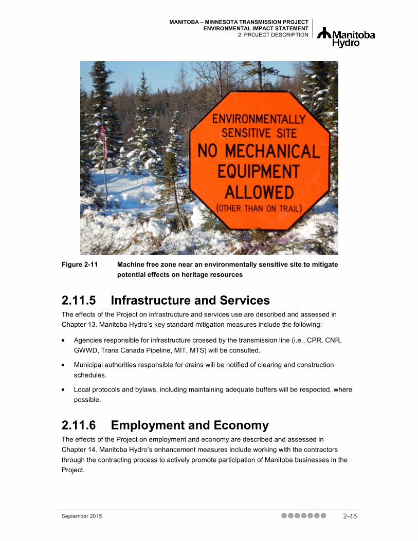
MANITOBA – MINNESOTA TRANSMISSION PROJECT ENVIRONMENTAL IMPACT STATEMENT
2: PROJECT DESCRIPTION
Figure 2-11 Machine free zone near an environmentally sensitive site to mitigate potential effects on heritage resources
2.11.5 Infrastructure and Services The effects of the Project on infrastructure and services use are described and assessed in Chapter 13. Manitoba Hydro’s key standard mitigation measures include the following:
• Agencies responsible for infrastructure crossed by the transmission line (i.e., CPR, CNR, GWWD, Trans Canada Pipeline, MIT, MTS) will be consulted.
• Municipal authorities responsible for drains will be notified of clearing and construction schedules.
• Local protocols and bylaws, including maintaining adequate buffers will be respected, where possible.
2.11.6 Employment and Economy The effects of the Project on employment and economy are described and assessed in Chapter 14. Manitoba Hydro’s enhancement measures include working with the contractors through the contracting process to actively promote participation of Manitoba businesses in the Project.
September 2015 2-45

MANITOBA – MINNESOTA TRANSMISSION PROJECT ENVIRONMENTAL IMPACT STATEMENT 2: PROJECT DESCRIPTION
2.11.7 Agriculture The effects of the Project on agriculture are described and assessed in Chapter 15. Manitoba Hydro’s key standard mitigation measures include the following:
• Manitoba Hydro will pay compensation pursuant to the Landowner Compensation Program for damage to infrastructure/crops from construction or maintenance activities. Where possible, construction schedules will take into consideration the timing of agricultural activities.
• Manitoba Hydro has developed an Agricultural Biosecurity Policy (Manitoba Hydro, 2013a) to prevent the introduction and spread of disease, pests and invasive plant species in agricultural land and livestock operations, and employees and contractors will follow this corporate policy and the Transmission Business Unit Agricultural Biosecurity Standard Operating Procedures (SOP) (Manitoba Hydro, 2015).
• Vehicular travel will be restricted to ROW and approved access routes.
2.11.8 Land and Resource Use The effects of the Project on land and resource use are described and assessed in Chapter 16. Manitoba Hydro’s key standard mitigation measures include the following:
• Subject to detailed engineering analysis, site-specific tower location (tower “spotting”) will be used, where feasible, to limit effects.
• Resource users, such as trappers and private woodlot owners, including Crown land encumbrance holders, will be notified in advance about the schedule for clearing and construction, and operations and maintenance.
• Information signs and warning markers will be used to identify the ROW where it intersects a recreational trail.
• If site-specific issues of concern arise, mitigation may be possible through, for example, maintaining a buffer of trees between a site/trail and the transmission line ROW.
• Existing access road and trails will be used to the extent possible.
2.11.9 Human and Ecological Health The effects of the Project on human health risk are described and assessed in the Chapter 18. Manitoba Hydro’s key standard mitigation measures include the following:
• Hearing protection will be provided by Manitoba Hydro and worn by all employees where workers may be exposed to high sound levels.
• Dust control measures will be applied as required during construction.
2-46 September 2015

MANITOBA – MINNESOTA TRANSMISSION PROJECT ENVIRONMENTAL IMPACT STATEMENT
2: PROJECT DESCRIPTION
2.12 Construction Process This section describes the schedule, workforce requirements and steps in the transmission line construction process.
2.12.1 Schedule and Workforce In total, clearing and construction of the D604I transmission line will require approximately 2 3/4 years to complete. This section describes the current schedule of activities and is subject to change. See Figure 2-13 for the anticipated construction schedule.
Transmission line construction for the Southern Loop Transmission Corridor will start in summer 2017 and will be completed by spring 2018. Construction during this period peaks during November and December of fall 2017 and winter 2018, when the average number of contractor workers on-site would be approximately 70. During the other months in this time period, approximately 50 contractor workers will be onsite. During the construction period for the SLTC, in addition to contractor workers, the number of Manitoba Hydro employees will peak at approximately 10.
Constructing the transmission line from Riel to the border will commence in spring 2018 and be completed by winter 2020. During this time, the workforce will peak in winter 2019, when the number of contractor workers onsite will be approximately 80. During this time, the number of Manitoba Hydro employees with peak at approximately 15 in winter 2019.
Transmission line realignment at Glenboro South Station will occur between spring and summer 2019. During this time, the number of contractor workers will peak at 15. A lot of the transmission line relocation work will be undertaken by Manitoba Hydro employees. During this time, the workforce will peak at 15.
The following sections discuss mobilization, ROW clearing, transmission line construction, access, marshalling yards, borrow sources, accommodations and construction camps, followed up by clean-up and demobilization.
2.12.2 Mobilizing Staff and Equipment The first step in clearing and construction is the mobilization of a workforce to an area. Mobilization includes the movement of Manitoba Hydro and contract staff, vehicles and equipment to the job site. Generally, mobilization is ongoing throughout the clearing and construction phase as different types of equipment are required for specific activities such as clearing, tower construction and conductor stringing. Start-up mobilization events are illustrated in the clearing and construction schedule for each component of the Project (Figure 2-12).
September 2015 2-47

MANITOBA – MINNESOTA TRANSMISSION PROJECT ENVIRONMENTAL IMPACT STATEMENT 2: PROJECT DESCRIPTION
Figure 2-12 Current Transmission Line Construction Schedule (*Subject to change, pending regulatory approval)
2.12.3 Access Route and Bypass Trail Development
Access for construction and subsequent line maintenance activities will generally occur along the ROW using existing public access roads or trails wherever possible. This enables maximum use of existing road access and limits the requirement for the development of new temporary trail access, and the associated environmental effects. Minor deviations (bypass trails) from the ROW may be necessary in severe terrain conditions. Unless required for ongoing maintenance, the ROW access trails will not be regularly maintained post construction.
Construction activity and access requirements will be subject to standard environmental protection measures associated with Manitoba Hydro’s transmission line construction practices. These will be identified and cross-referenced in site-specific Environmental Protection Plans (to be submitted for review and approval), and adherence to them will be stipulated in related contract specifications.
At waterway crossings, structures will be located as far back from the water’s edge as possible, to enhance stability and prevent bank erosion. Construction procedures used at each required crossing will be based on site-specific considerations, such as existing soil and subsurface conditions, biophysical sensitivities, and operational requirements. Site-specific construction techniques will be developed where necessary for difficult terrain or steep slope conditions. Contractors will be required to develop sediment and erosion control plans.
Equipment access and construction activities will be carried out in a manner that will limit disturbance to shorelines. Vegetative buffer zones will be retained along the shorelines wherever possible. The precise character and extent of buffer zones will be determined on a site-specific basis. In general, existing (and potential future) tree heights will govern the amount of clearing that must be done in buffer zones to make sure operation of the line is safe.
Existing intersections, such as those for trails, provincial trunk highways (PTHs), provincial roads (PRs) and railways, are considered sensitive to change or conflicting land uses. Use of trails is important for recreational, commercial and subsistence hunters, gatherers and trappers. Ensuring
2-48 September 2015

MANITOBA – MINNESOTA TRANSMISSION PROJECT ENVIRONMENTAL IMPACT STATEMENT
2: PROJECT DESCRIPTION
there is safe access to these trails is important to limit effects on resource users. In conjunction with general mitigation measures, a standalone document, the Access Management Plan (AMP), has been developed to safeguard and support the preservation of environmental, socio-economic, cultural and heritage values within the Project’s area of direct effect in the creation of new access.
2.12.4 Right-of-Way Clearing and Geotechnical Investigations
2.12.4.1 Right-of-Way Clearing Clearing and disposal of trees on the proposed ROW will be undertaken in advance to facilitate construction activities. Right-of-way clearing will be subject to standard environmental protection measures, which have been established in association with Manitoba Hydro transmission line construction practices, as well as the Construction Environmental Protection Plan. With the exception of environmentally sensitive areas, the cleared ROW width for the structures will vary depending on location and tower type. Clearing will be modified in environmentally sensitive areas (e.g., river and stream crossings) (Figure 2-13) and will be subject to a variety of pre-determined but adaptable environmental protection measures.
Figure 2-13 Riparian Buffer in transmission line ROW
September 2015 2-49

MANITOBA – MINNESOTA TRANSMISSION PROJECT ENVIRONMENTAL IMPACT STATEMENT 2: PROJECT DESCRIPTION
Clearing requirements for the new transmission line rights-of-way will also require selective clearing of “danger trees” beyond the ROW. Such trees could potentially affect the function of the transmission line or result in safety concerns, and are normally identified during initial ROW clearing activities and removed. A variety of methods is available for ROW clearing. Typically, these include conventional clearing done by “V” and KG” blades on tracked bulldozers (Figure 2-13), mulching by rotary drums (Figure 2-14), selective tree removal by feller bunchers (Figure 2-15) (e.g., for removal of danger trees with minimal adverse effect on adjacent vegetation and trees) and hand clearing with chain saws in environmentally sensitive sites. Final clearing methods will be determined based on detailed surveys of the transmission line routes, and site-specific identification of environmentally sensitive features.
Figure 2-14 Vegetation management with a mulcher along the ROW
2-50 September 2015

MANITOBA – MINNESOTA TRANSMISSION PROJECT ENVIRONMENTAL IMPACT STATEMENT
2: PROJECT DESCRIPTION
Figure 2-15 Danger tree removal by a feller buncher
Trees within the ROW will be cleared to a maximum height of approximately 10 cm (4 inches) above the ground. Ground vegetation will not be “grubbed” except at tower sites, where the foundation area will typically be scraped to allow unencumbered access for equipment and safe walking areas for workers. Disposal of cleared vegetation typically involves a variety of options including piling and burning, mulching, collection and secondary use by local communities (e.g., firewood), or salvage and marketing of merchantable timber resources if feasible. The final decision for disposal of vegetation will be determined based on the method of clearing used and the environmental license conditions applied to the Project. Apart from removal of danger trees along the ROW edges, clearing procedures are normally confined to the ROW. Where access outside the ROW is necessary (e.g., bypass trails) and has not been identified in advance, supplementary approvals, if required, will be obtained from the Manitoba Government (e.g., work permits and timber permits relating to activity on provincial Crown lands) or from individual landowners.
2.12.4.2 Geotechnical Investigations Geotechnical investigations involve the excavation of test pits and in some instances such as angle towers soil drilling to create a soil profile that is used by civil designers in the development of specialty foundations. Investigations take place as the ROW is cleared to allow access. Test pits located at tower foundation sites are excavated by a tracked excavator. They are backfilled once tests are complete (Figure 2-16).
September 2015 2-51

MANITOBA – MINNESOTA TRANSMISSION PROJECT ENVIRONMENTAL IMPACT STATEMENT 2: PROJECT DESCRIPTION
Figure 2-16 A test pit located at a tower foundation as part of geotechnical excavations for specialty towers
2.12.5 Transmission Tower Construction and Conductor Stringing
Transmission line construction involves several stages, installing tower foundations and anchors (Figure 2-18), assembling and erecting structures (Figure 2-19), and stringing of the conductor and overhead ground wires (Figure 2-20). The different stages entail the use of various types of vehicles and heavy equipment, and involve a range of skills and trades.
2-52 September 2015

MANITOBA – MINNESOTA TRANSMISSION PROJECT ENVIRONMENTAL IMPACT STATEMENT
2: PROJECT DESCRIPTION
Figure 2-17 Installation of tower foundations and anchors
Figure 2-18 A tower structure assembled at a marshalling yard erected by crane
September 2015 2-53

MANITOBA – MINNESOTA TRANSMISSION PROJECT ENVIRONMENTAL IMPACT STATEMENT 2: PROJECT DESCRIPTION
Figure 2-19 Stringing Conductor
At this stage, both structure and conductor designs are subject to final detailed design. Unless otherwise specified, the following descriptions are based on current design and on prior experience with similar projects and conditions. The dimensions provided for the various structure and foundation types are subject to revision in the course of final design and confirmation of field construction conditions.
For the guyed suspension lattice steel structures, design and construction of the tower foundations will depend on soil and terrain conditions. For surface or shallow bedrock conditions, the lattice structures will be founded on a steel column fixed directly to the rock by steel dowels drilled and grouted into the rock. Where rock is not encountered, the structures will be founded on mat footings, sized to provide adequate bearing support (typically in the order of 1.8 m [6 ft.] square) and buried to a depth of approximately 3 m (10 ft.). Depending on soil conditions, deep foundations (i.e., piles) may also be used.
For shallow or surface bedrock conditions, guy anchors will be secured by drilled and grouted anchors. Where bedrock is not encountered, deadman anchors, or other deep anchors (e.g., screw anchors, overburden) will be used.
Self-supporting suspension lattice steel structures will be supported by either mat or pile foundations. Mat foundations will typically be 3 m2 (9.8 ft.) by 3 m2 (9.8 ft.) deep (Figure 2-21). Pile foundations will involve individual piles or pile groups, one for each leg of the structure (Figure 2-22). Piles may be cast-in-place concrete, generally 900 mm (36 in.) in diameter and approximately 10 m (33 ft.) in length, or steel pile groups with a welded cap (similar in footprint to concrete piles).
2-54 September 2015

MANITOBA – MINNESOTA TRANSMISSION PROJECT ENVIRONMENTAL IMPACT STATEMENT
2: PROJECT DESCRIPTION
Figure 2-20 Mat foundations used to support self-supporting suspension lattice steel structures
Figure 2-21 Pile foundations used to support self-supporting suspension lattice steel structures
September 2015 2-55

MANITOBA – MINNESOTA TRANSMISSION PROJECT ENVIRONMENTAL IMPACT STATEMENT 2: PROJECT DESCRIPTION
Guyed triple-shaft dead-end structures will be founded similarly to guyed suspension structures but will require a separate foundation for each of the three vertical members. In the case of mat footings, their dimension will be in the order of 1.8 × 3.6 m (6 × 12 ft.).
Self-supporting angle and dead-end structures will be supported by either mat or pile foundations. Mat foundations will typically be 4 m2 (13.1 ft.) by 3 m2 (9.8 ft.) deep, for each leg of the structure. Pile foundations will typically consist of four 1200 mm (48 in.) diameter concrete piles approximately 11 m (36 ft.) in depth, or steel pile groups with a welded cap (of similar footprint to concrete piles). Dimensions will be subject to detailed design and will vary for specific foundation conditions.
Where necessary (e.g., in the case of organic soils), foundation excavations will be backfilled with soil or granular material. Where wet or unstable soil conditions are encountered, the mat foundations may be installed inside a large diameter steel culvert section to provide additional stability. These requirements may be limited to guyed tangent or suspension structures.
Different contractors will have different preferences with respect to structure assembly. Some will choose to assemble structures at each tower site and then erect them by crane. Others will choose to assemble the structures at a central marshalling yard and then either truck the structures to the site and erect them by crane (Figure 2-23), or use a helicopter to fly the towers to the site and erect them (Figure 2-24).
Figure 2-22 Erecting Tower by Crane
2-56 September 2015
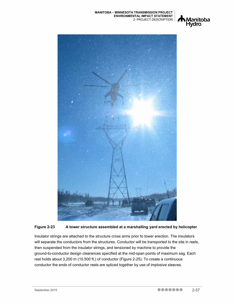
MANITOBA – MINNESOTA TRANSMISSION PROJECT ENVIRONMENTAL IMPACT STATEMENT
2: PROJECT DESCRIPTION
Figure 2-23 A tower structure assembled at a marshalling yard erected by helicopter
Insulator strings are attached to the structure cross arms prior to tower erection. The insulators will separate the conductors from the structures. Conductor will be transported to the site in reels, then suspended from the insulator strings, and tensioned by machine to provide the ground-to-conductor design clearances specified at the mid-span points of maximum sag. Each reel holds about 3,200 m (10,500 ft.) of conductor (Figure 2-25). To create a continuous conductor the ends of conductor reels are spliced together by use of implosive sleeves.
September 2015 2-57

MANITOBA – MINNESOTA TRANSMISSION PROJECT ENVIRONMENTAL IMPACT STATEMENT 2: PROJECT DESCRIPTION
Figure 2-24 Conductors are transported to the site in reels before suspension from the insulator strings
2.12.6 Marshalling Yards Marshalling yards, as shown in Figure 2-26 will typically be established near the transmission line route for the storage of construction materials and equipment and for further deployment to the construction site. The exact number and location of marshalling yards will be determined during the course of developing detailed construction specifications and contract arrangements.
2-58 September 2015
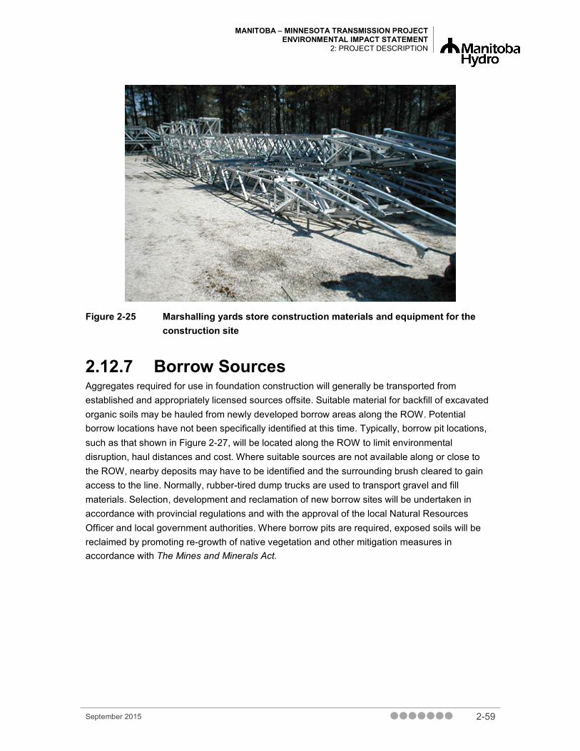
MANITOBA – MINNESOTA TRANSMISSION PROJECT ENVIRONMENTAL IMPACT STATEMENT
2: PROJECT DESCRIPTION
Figure 2-25 Marshalling yards store construction materials and equipment for the construction site
2.12.7 Borrow Sources Aggregates required for use in foundation construction will generally be transported from established and appropriately licensed sources offsite. Suitable material for backfill of excavated organic soils may be hauled from newly developed borrow areas along the ROW. Potential borrow locations have not been specifically identified at this time. Typically, borrow pit locations, such as that shown in Figure 2-27, will be located along the ROW to limit environmental disruption, haul distances and cost. Where suitable sources are not available along or close to the ROW, nearby deposits may have to be identified and the surrounding brush cleared to gain access to the line. Normally, rubber-tired dump trucks are used to transport gravel and fill materials. Selection, development and reclamation of new borrow sites will be undertaken in accordance with provincial regulations and with the approval of the local Natural Resources Officer and local government authorities. Where borrow pits are required, exposed soils will be reclaimed by promoting re-growth of native vegetation and other mitigation measures in accordance with The Mines and Minerals Act.
September 2015 2-59

MANITOBA – MINNESOTA TRANSMISSION PROJECT ENVIRONMENTAL IMPACT STATEMENT 2: PROJECT DESCRIPTION
Figure 2-26 A borrow pit located along the transmission line ROW supplies aggregates for the Project
Any use of explosives during transmission line construction (e.g., in borrow pit operations, foundation installation, conductor splicing) will be made in accordance with all applicable legislation and regulations, including acquisition of permits.
2.12.8 Accommodations and Construction Camps
It is anticipated that clearing and construction workers will be housed in suitable accommodations available in local communities where feasible and practical with the possibility of mobile construction camps if required. If needed, mobile construction camps would include sleeper units, a wash car, cooking and eating trailers, offices and a machine/parts shop similar to that shown in Figure 2-28. These camps will generally be relocated along the ROW as various construction activities proceed. Camp size could be in the range of 10 to as many as 100 workers, but will vary according to the activity, contract size and labour force requirements.
Mobile construction camps will generally be located in well-drained areas within the ROW or in pre-disturbed locations with access to electrical supply. Additional clearing may be required, however, to facilitate vehicular traffic, transportation and distribution of construction materials, and installation of temporary maintenance shops, kitchens, sleeping quarters, offices. Specific field camp locations will be determined after final Project planning and design are completed. As
2-60 September 2015

MANITOBA – MINNESOTA TRANSMISSION PROJECT ENVIRONMENTAL IMPACT STATEMENT
2: PROJECT DESCRIPTION
construction moves down the line, the camps will be relocated at intervals of approximately 60 to 80 km (about 35 to 50 mi.) to limit travel time for workers. Potable water will generally be transported to the camps and stored in cisterns. Wastewater will typically be stored in licensed holding tanks that will be pumped and disposed of at licensed waste-disposal grounds to limit the potential for surface or groundwater contamination. All mobile construction campsites will be restored to pre-Project condition with the exception of vegetation, which will be allowed to regenerate naturally on the sites.
Figure 2-27 A mobile construction camp supports construction workers
2.12.9 Demobilization The final step in clearing and construction is the demobilization of a workforce from an area. Demobilization includes the movement of Manitoba Hydro and contract staff, vehicles and equipment from the job site, as well as the clean-up (and if required rehabilitation) of camps, marshalling yards, borrow sources and access routes. Generally, demobilization is ongoing throughout the clearing and construction phase as different types of equipment are required for specific activities such as clearing, tower construction and conductor stringing. Construction cleanup will occur throughout clearing and construction. As soon as possible after completion of construction, the sites will be cleaned up and left in standard operating condition. All non-toxic materials will be disposed of using existing, appropriately licensed local facilities. Material supply and waste handling will be subject to conventional Manitoba Hydro codes of practice and relevant provincial and federal legislation. All cleanup and rehabilitation activity will be subject to the requirements of the Environmental Protection Plan.
September 2015 2-61

MANITOBA – MINNESOTA TRANSMISSION PROJECT ENVIRONMENTAL IMPACT STATEMENT 2: PROJECT DESCRIPTION
2.13 Transmission Line Operation and Maintenance
2.13.1 Inspection Patrols Manitoba Hydro conducts inspection of all its 200 kV and greater transmission lines and ROW corridors annually in addition to dealing with emergencies. The inspections include, but are not limited to, vegetation management, repairing foundations and insulators, and removing ice build-up. Crews triage infrastructure during emergencies to address line outages and tower damage. Following the inspection, all pertinent information and findings are entered into a transmission line management database program. From this central database, annual maintenance activities are identified and tracked.
The annual patrol is conducted either by ground or by air depending on access, geographic conditions and time of year. Non-scheduled patrols, by ground or air, may be conducted if the Manitoba Hydro System Control Center identifies a fault on the line that requires visual inspection. Patrols are normally undertaken by snow machine, all-terrain vehicles, light trucks or helicopter, depending on the geographical location and ease of access.
Maintenance procedures are well established and are the subject of continuously updated corporate guidelines for maintenance and construction activities. Maintenance activities include instances where crews are required to obtain access to specific areas to repair deficiencies on the transmission system. Maintenance repairs are typically done during winter, after frost has entered the ground, using heavier soft track equipment to gain access. When summer access is required in agricultural areas, related maintenance activities are planned, wherever possible, to avoid conflict with farm activity.
In circumstances where maintenance activity requires the use of access trails off the ROW (e.g., difficult terrain), approval is first obtained from Manitoba Conservation, when on provincial Crown land. In areas where access to or across private lands is required, or if working within private lands under easement, the landowners are contacted in advance.
2.13.2 Workforce Requirements Workforce requirements associated with the operations and maintenance of a particular transmission line generally involve deployment of established regional operations and maintenance personnel, and contractor staff as required. Line inspections could involve concurrent inspections of various lines in the region. Maintenance would include repairs as required. The workforce for regular maintenance activities could be between three and five workers. During emergencies, the size of the workforce is largely dictated by the work required.
2-62 September 2015

MANITOBA – MINNESOTA TRANSMISSION PROJECT ENVIRONMENTAL IMPACT STATEMENT
2: PROJECT DESCRIPTION
2.13.3 Vegetation Management Vegetation management is required on an ongoing basis to make sure that regrowth in the cleared ROWs does not interfere with transmission line operations. Related management procedures extend to periodic review and removal of danger trees in the immediate vicinity of the ROW. Manitoba Hydro is also subject to NERC reliability standard requirements, which have been adopted in Manitoba under Manitoba Regulation 25/2012. Currently effective standard FAC003-1 stipulates that vegetation control be conducted along ROWs to prevent situations from arising where trees can cause an outage on transmission lines 200 kV or greater (NERC 2006).
Integrated vegetation management involves a variety of methods, including hand cutting (e.g., using chainsaws, brush saws, axes, or brush hooks) and mechanical shear blading using “V” or “KG” blades. KG blades are bulldozer blades with a sharpened lower edge or are angled V-shaped for splitting large trees and stumps. With care, trees can be sheared at ground level and felled or piled (windrowed) with little soil disturbance. Brush mowing with rotary and drum cutters (typically rubber-tired equipment), and herbicide treatments are also used. The methods above are typically conducted on foot, or by all terrain or flex-tracked vehicles. Due to access constraints in some areas, brushing may be completed during the winter months using the shear blading method. In agricultural areas, vegetation management schedules are adjusted to accommodate farming schedules. The vegetation maintenance brushing cycle for transmission line rights-of-way typically ranges between 8 and 10 years.
This type of integrated vegetation management approach is used in order to maintain a safe, reliable and uninterrupted transmission of electric energy. The focus of vegetation management is on the tall growing tree species that have the potential to grow or fall into, or within, the arcing distance of the transmission lines and or facilities and cause an outage. The management practices that may be used to control vegetation incorporate mechanical, chemical, biological or cultural options depending upon a number of factors including site conditions and the sensitivity of surrounding areas.
Herbicide treatments are formulated to target undesirable tall growing trees but are also effective on broadleaf weeds, leaving grasses unaffected. Foliar applications of herbicides are applied during the warmer months while dormant stem applications are typically applied in the fall and winter. Permits for pesticide use are obtained as required. The process involves public notification as part of the formal permit application to Manitoba Conservation and Water Stewardship’s Pesticide Approvals Branch.
All herbicide applications are completed and supervised by licensed applicators and in accordance with conditions specified in the Pesticide Use Permit. Herbicide application rates at Manitoba Hydro are established by their Chief Forester in accordance with product label instructions. Only herbicides that have been listed in the Pesticide Use Permit are used by Manitoba Hydro. Manitoba Hydro has developed a pesticide applicator requirements document for their employees to provide regulatory and applicator licensing information; technical guidance; safety requirements and checklists for line managers responsible for pesticide application for ensuring compliance with legal requirements. In addition, it provides information so that
September 2015 2-63
MANITOBA – MINNESOTA TRANSMISSION PROJECT ENVIRONMENTAL IMPACT STATEMENT 2: PROJECT DESCRIPTION
consistent pesticide management is conducted at all Manitoba Hydro facilities, thereby ensuring pesticide management is conducted in such a way that the resulting environmental effect is minimal.
Several methods of herbicide application are available. High volume broadcast stem/foliar application equipment, used for tree heights of 2.5 m (8 ft.) or less, includes droplet applicators (such as Radiarc and Vecta-Spray sprayers), boom busters, and hose and handgun sprayers. Aerial foliar spraying has also been used as an application technique and could be used in the future. Selective stem/foliar applications (both high and low volume) are the preferred method for tree heights of 2.5 m (8 ft.) or less, and are made with hose and handgun sprayers, or backpack sprayers.
Individual stem treatment includes thin line or similar basal treatment applications made with hand-held equipment to direct a low-pressure stream to the lower tree stem, or tree injection techniques. These can be completed at any time of year and on trees over 2.5 m (8 ft.) in height, and are used in circumstances where selective treatment is necessary for environmental or. Wherever practical, stump treatment is used following hand-cutting to provide selective control of suckering for deciduous species and to limit effects on desirable vegetation.
In addition to tree control, weed control on the ROWs may be required under the The Noxious Weeds Act (C.C.S.M. c. N 110). In agricultural areas, continued cultivation will reduce the need for weed control. Alternative techniques for the uncultivated portions of the ROW include mowing and herbicide spraying, which is the most effective method to control weed growth. Spraying equipment includes backpack sprayers, truck-mounted power sprayers equipped with a broadcast applicator system, hose and handgun, and all-terrain vehicle mounted power sprayers.
Prior to any vegetation management work on private land under easement agreement with Manitoba Hydro, the land owner will be notified and permission requested for access across land to get to ROW. On provincial Crown lands, a work permit issued under The Forest Act (F150) is required and owners adjacent to the ROW. Manitoba Hydro’s Chief Forester is responsible for obtaining the necessary Pesticide Use Permits and submitting Post Seasonal Control Reports as per Manitoba Regulation 94-88R under The Environment Act.
Manitoba Hydro’s Agricultural Biosecurity Policy
Manitoba Hydro’s Agricultural Biosecurity Policy was created to prevent the introduction and spread of disease, pests and invasive plant species in agricultural land and livestock operations. Manitoba Hydro employees and contractors will follow this corporate policy and the Transmission Business Unit Agricultural Biosecurity Standard Operating Procedures (SOP). In relation to this policy, agricultural land is defined as land zoned for agricultural use by the provincial government, planning commission or planning district.
Manitoba Hydro staff and contractors have the potential to affect agricultural biosecurity through construction and maintenance activities that require access to agricultural land. Acknowledging this risk, the purpose of the agricultural biosecurity corporate policy is to make sure Manitoba
2-64 September 2015

MANITOBA – MINNESOTA TRANSMISSION PROJECT ENVIRONMENTAL IMPACT STATEMENT
2: PROJECT DESCRIPTION
Hydro staff and contractors take necessary precautions to protect the health and sustainability of the agricultural sector.
The transmission SOP and the training associated with it apply to all the employees of Transmission Business Unit as well as external contractors or consultants who conduct work on behalf of the Transmission Business Unit and are required to enter agricultural land. The SOP includes procedures to provide guidance and direction to staff and contractors/consultants who may be required to enter agricultural land and the levels of cleaning necessary to reduce the likelihood of soil and manure transport of invasive species, pests or disease. More information on the SOP is provided in Chapter 22 – Environmental Protection, Follow-up and Monitoring.
2.13.4 Electric and Magnetic Fields and Corona Operation of any transmission line involves the production of electric and magnetic fields (EMF) and corona discharges. Corona discharges, in turn, may result in audible noise and low frequency electrical interference. The level of these will vary with time, subject to variations in the operating mode and loading conditions of the line and, as well, to final line design, conductor condition, and external considerations such as meteorological conditions. Estimated levels of these emissions and related effects have been based on mathematical modeling and on comparison to corresponding levels associated with other existing lines in the Manitoba Hydro system.
Concerns respecting the potential for environmental effects (e.g., health effects, electrostatic and electromagnetic induction effects, and communications interference arising from EMF and corona emissions) were raised in the course of the public and First Nation and Metis engagement processes for the Project. These concerns, together with assessment of potential effects and related mitigation measures, are discussed in Chapter 18 – Human Health Risk and Chapter 13 – Infrastructure and Services.
2.14 Transmission Line Decommissioning Should these transmission lines be decommissioned at some future date, Manitoba Hydro will apply acceptable means for environmentally restoring Project sites and ROWs.
Current methods of transmission line decommissioning entail the dismantling of the structures and salvage or disposal of all steel structure components, as well as removal and salvage of insulators, conductors and ground wires. Decommissioning of ROWs currently involves clean up and remediation to a standard commensurate with local environmental conditions, including the applicable land use and policy in effect at the time of decommissioning.
September 2015 2-65

MANITOBA – MINNESOTA TRANSMISSION PROJECT ENVIRONMENTAL IMPACT STATEMENT 2: PROJECT DESCRIPTION
2.15 Station Modifications and Additions With the small scale nature of modifications and additional equipment being required at Dorsey and Riel converter stations and Glenboro South Station, it is anticipated that there will be minimal new interactions with the environment. Modifications at these stations are required specifically for the Project as well as for overall system reliability reasons. Established procedures, protocols and standards are in place to protect the safety of the public, workers and the environment during the Project construction and operation and maintenance phases. Standard environmental protection measures that are intended to mitigate potential environmental effects will be followed during site preparation and construction activities and will be outlined in a CEnvPP for the station components of the Project. Further discussion on the CEnvPP is provided in Chapter 22 - Environmental Protection, Follow-up and Monitoring.
At the Dorsey Converter Station, the principal electrical components include circuit breakers, capacitors, reactors and related equipment required to terminate the D604I Transmission line (Appendix 2A – Station Equipment List).
At the Glenboro South Station, the principal electrical components to be installed are two-phase shifting transformers and associated equipment (Appendix 2A – Station Equipment List). A phase shifting transformer is a special type of transformer that controls the flow of electricity in a transmission line. Unexpected power flow from the United States through the Manitoba Hydro electrical system which flows back (loop flow) to the United States can occur as part of normal system operating. The addition of the D604I transmission line could exacerbate this effect without the addition of phase shifting transformers. A phase shifting transformer functions like a control switch to block these unfavorable power flows and is used for congestion management purposes. To accommodate the new phase shifting transformers, the site will need to be expanded on Manitoba Hydro owned property.
At the Riel Converter Station, the principal electrical addition to the station is the installation of a second auto transformer and associated equipment (Appendix 2A – Station Equipment List). Autotransformers are often used to interconnect systems operating at different voltage classes (i.e., step up or step down between different voltages – 230 kV to 500 kV) or can act as voltage controllers, so that customers at the far end of a transmission line receive the same average voltage as those closer to the source. All station upgrades will occur within the existing fenced area.
The following sections provide details on the modifications and additions that will be occurring at each station.
2-66 September 2015

MANITOBA – MINNESOTA TRANSMISSION PROJECT ENVIRONMENTAL IMPACT STATEMENT
2: PROJECT DESCRIPTION
2.15.1 Dorsey Converter Station The Dorsey Converter Station is located near the town of Rosser, Manitoba, about 6 km northwest of the perimeter highway outside of Winnipeg. Built in 1968, Manitoba Hydro’s Dorsey Converter Station is the southern terminus for the utility’s high voltage direct current transmission lines. There are two main components to the converter station 500 kV Switchyard and the 230 kV Switchyard, shown in Figure 2-29 that are used to convert and distribute electricity in southern Manitoba.
Figure 2-28 Aerial Photo of Dorsey Converter Station
2.15.1.1 Dorsey Converter Station Activity Overview As a result of the construction of the Project, modifications and additions will be required at the Dorsey Converter Station. Modifications in the 500 kV switchyard will include 500kV bus extension and bay modifications (i.e., structures) and the addition of a 500 kV breaker, 500 kV single-phase current transformers, a 500 kV line termination and 500 kV single phase shunt reactors.
Components within the expansion of the new 500 kV yard will include all the necessary concrete foundations, steel structures and equipment supports. Equipment foundations will range from concrete slab-on-grade to deep piled foundations, depending on equipment weight and geotechnical conditions. Steel structures will be placed on the foundations and will support electrical apparatus and electrical conductors, and hardware associated with the switchyard as shown in Figure 2-30. The switchyard will be air-insulated. A fence extension is required further west of the site. The proposed expansion will require an area of approximately 15,900 m2 west.
September 2015 2-67

MANITOBA – MINNESOTA TRANSMISSION PROJECT ENVIRONMENTAL IMPACT STATEMENT 2: PROJECT DESCRIPTION
There will be also modifications carried out in the 230 kV yard. All the existing bus support 230 kV post insulators will be replaced with extra high-strength 230 kV post insulators.
Figure 2-29 Switchyard
Workforce and schedule
Work at Dorsey Converter Stationis currently scheduled to commence in spring 2018 and will be completed by fall 2019 (Figure 2-30). There are only two months at the start of construction that will have contractors onsite. During the remaining time, exclusively Manitoba Hydro employees will be onsite and the number of staff will peak at 27 employees in total.
Figure 2-30 Current Station Schedule (*Subjet to change, pending regulatory approval)
2-68 September 2015

MANITOBA – MINNESOTA TRANSMISSION PROJECT ENVIRONMENTAL IMPACT STATEMENT
2: PROJECT DESCRIPTION
2.15.1.2 Site Preparation The station site will be expanded to the west to accommodate the new transmission line termination (Figure 2-31). The site expansion will be 40 m × 273 m and 53 m × 94 m for a total of approximately 15,902 m2 west on Manitoba Hydro owned property. Salvage of 175 linear meters of existing fencing and the installation of 420 linear meters of new fence will occur at the site and the relocation of two station vehicle gates.
Figure 2-31 Dorsey Expansion
The site development will take into account both existing drainage patterns surrounding the site and the need to protect the existing station from overland flooding during spring runoff or an extreme rainfall event. Additional localized drainage may be required. A newly developed drainage system for the expansion will integrate the existing site grading and drainage design.
All newly developed areas will be covered with an insulation stone course, approximately 150 mm in thickness, and typically consisting of 20–40 mm diameter clean stone aggregate.
2.15.1.3 Oil Storage and Containment No long-term storage of insulating oil during construction is anticipated. Insulating oil will be brought to site as required. See Appendx 2A – Station Equipment List for quantities.
An oil containment assessment is carried out at for all new stations and station modifications to determine the level of containment required. If it is determined that oil containment is required to contain any discharge of oil from equipment to limit effects on the environment, oil containment for the expansion of Dorsey Converter Station will follow the existing oil containment plan for the converter and 500 kV stations. These could include a combination of non-point and point containment for oil-filled equipment. Non-point containment for small equipment is managed by
September 2015 2-69

MANITOBA – MINNESOTA TRANSMISSION PROJECT ENVIRONMENTAL IMPACT STATEMENT 2: PROJECT DESCRIPTION
surface grading. Point containment is required for large equipment containing greater than 5000 litres of oil. This protection consists of containment pits around the equipment (Figure 2-32; Figure 2-33). Both point and non-point containment will direct any potential contaminates through oil water separator building(s) and containment ponds.
Figure 2-32 Oil Containment for a Transformer
Figure 2-33 Oil Containment for Multiple Pieces of Equipment
2-70 September 2015

MANITOBA – MINNESOTA TRANSMISSION PROJECT ENVIRONMENTAL IMPACT STATEMENT
2: PROJECT DESCRIPTION
2.15.1.4 Station Grounding The primary purpose of station grounding is to provide personnel, public and equipment safety through a grounding grid. The grounding grid makes sure people inside and outside a station are not exposed to critical electrical shock under normal and fault conditions. Furthermore, it also provides a means to bond the equipment to ground. The Canadian Electrical Code requires that all metallic objects in an outdoor station be bonded to ground.
A grounding grid is made up of mesh copper conductors and ground rods buried in the station soil. The grounding grid system normally encompasses the entire station site and extends 1 m past the station fence and gate swings. At Dorsey Converter Station, the ground grid will be expanded and tied into the existing system to account for the new equipment and provide equipment grounding connection points. As a result of the expansion, additional copper conductors, ground rods and switch mats will be installed.
2.15.1.5 Station Protection The purpose of protection system equipment is to detect an abnormal event or disturbance within the power system (e.g., a lighting strike creating a fault) and to disconnect the faulted piece of equipment within a fraction of a second. A fault is a short circuit in the power system that can result in abnormally high or low currents and voltages. Protection equipment monitors for abnormal voltages and currents and if it determines that there is an abnormality, de-energizes the faulty equipment at the station by tripping a power circuit breaker. Protection system equipment includes the following components: protection relays (located in the control building), current transformers (CTs), capacitive voltage transformers and power circuit breakers. At Dorsey Converter Station, new protection systems will be installed for all new switchyard equipment including the transmission line, line reactors.
The 500 kV line protection will be designed to permit Single Pole Trip and Reclose of the 500 kV transmission line. What this means is that in the event that protection equipment identifies a problem with the transmission line, instead of tripping all three phases, only one phase (i.e., the faulted phase) will be tripped and re-energized to allow the two other phases to continue to distribute electricity from the Dorsey Converter Station.
2.15.1.6 Communications The Project includes installation of communication infrastructure at the site (e.g., teleprotection and telemetry). This infrastructure facilitates reliable operation of the transmission line and station related components and is comprised of equipment related to protection and control of the power system and fibre optic cable systems. Protection and control signals that are to be sent to the United States (e.g., remote end of line) and to other Manitoba Hydro facilities will use existing fibre optic and microwave radio systems, and the new optical ground wire (OPGW) to be installed as part of this Project.
September 2015 2-71

MANITOBA – MINNESOTA TRANSMISSION PROJECT ENVIRONMENTAL IMPACT STATEMENT 2: PROJECT DESCRIPTION
2.15.1.7 Foundations Concrete piles and slabs on grade foundations will be required to support installation of structures and equipment at the station. Foundations to attach steel lattice structures to support electrical components and bus work will largely consist of concrete caps on deep piles at all column locations as shown in Figure 2-34.
Figure 2-34 Example of two caps on deep pile foundations
Piles will be designed to resist frost heaving; the depth of the piles will be approximately thirty feet deep. The piles will be approximately 600 mm to 1050 mm in diameter. The piles will be cast-in-place, which involves drilling a shaft into the soil, placing a reinforcing cage and filling it with concrete (Figure 2-34).
Slab on grade foundations without piles will also be used for low-seated equipment such as station service transformers (Figure 2-35). Slab-on-grade foundations can vary in size dependent on equipment footprint but typically can range 6 ft. by 6 ft. or more.
2-72 September 2015

MANITOBA – MINNESOTA TRANSMISSION PROJECT ENVIRONMENTAL IMPACT STATEMENT
2: PROJECT DESCRIPTION
Figure 2-35 Foundation (farthest in photo) is an example of a slab on grade foundation
Slab on grade foundations supported by multiple piles are often used for standalone equipment such as air circuit breakers, transformers, switches and reactors, for example. Figure 2-36 is an example of a slab-on-grade foundation on top of piles for a large transformer.
Figure 2-36 Example of slab on grade foundation on piles
In total, approximately 134, 500/138 kV foundations will be installed. Eighteen 46 kV foundations will be installed and of two cable trenches will be added.
September 2015 2-73

MANITOBA – MINNESOTA TRANSMISSION PROJECT ENVIRONMENTAL IMPACT STATEMENT 2: PROJECT DESCRIPTION
2.15.1.8 Steel Structures A variety of steel structures will be installed at the site for new equipment (Figure 2-37). Standalone equipment required for the station will have steel supporting structures that are manufactured supplied and then attached to foundations (e.g., breakers).
Figure 2-37 Example of manufactured steel supporting structures for a capacitor
Tubular steel stand structures will also be used to support the following types of equipment at the station that will be installed: CTs, potential transformers (PTs), arrestors, and wave traps (Figure 2-38). The tubular steel structures will range in height from 3 m to 7 m.
2-74 September 2015

MANITOBA – MINNESOTA TRANSMISSION PROJECT ENVIRONMENTAL IMPACT STATEMENT
2: PROJECT DESCRIPTION
Figure 2-38 Example of tubular steel structures for bus work and related equipment
Steel lattice structures are typically taller to accommodate clearances for required voltages on equipment such as bus conductors, and will be used for the installation of new equipment (Figure 2-39). Steel lattice structures will be approximately 6 to 15 m tall, depending on the equipment the structures are supporting.
Figure 2-39 Example of steel lattice structures
September 2015 2-75

MANITOBA – MINNESOTA TRANSMISSION PROJECT ENVIRONMENTAL IMPACT STATEMENT 2: PROJECT DESCRIPTION
Approximately 115, 500/138 kV steel structures will be installed onsite. Modification to two post insulators structures in the 230 kV yard will also occur with the addition of 13 46 kV structures.
2.15.1.9 Station Lighting Lighting expansion required for the station expansion includes the installation of an additional two 150 W perimeter light masts as a result of the station fence expansion and four 750 W HPS floodlights lights mounted new steel structures.
2.16 Riel Converter Station The Riel Converter Station is located east of the Red River floodway and north of the City of Winnipeg’s Deacon Water Supply Reservoir in the Rural Municipality of Springfield (Figure 2-40; Figure 2-41). The station is built on 112 ha of land owned by Manitoba Hydro. The site has a dual purpose and is presently under development for the previously approved and licensed Riel Reliability Improvement Initiative and the construction of the Riel Converter Station required for the Bipole III complex.
Figure 2-40 Riel Converter Station
2-76 September 2015

MANITOBA – MINNESOTA TRANSMISSION PROJECT ENVIRONMENTAL IMPACT STATEMENT
2: PROJECT DESCRIPTION
Figure 2-41 Aerial Photo of Riel Converter Station
2.16.1 Riel Converter Station Activity Overview As a result of the construction of the Project, modifications will be required at the Riel Converter Station. Modifications in the 500 kV yard at Riel will include a new 500 kV-230 kV autotransformer, 500 kV and 230 kV breakers, 500 kV and 230 kV single-phase current transformers. Components within the 500 kV yard will include all the necessary concrete foundations, steel structures and equipment supports. Equipment foundations will range from concrete slab-on-grade to deep piled foundations, depending on equipment weight and geotechnical conditions. Steel structures will be placed on the foundations and will support electrical apparatus and electrical conductors, and hardware associated with the switchyard. All modifications will be located within the existing station fenced area.
September 2015 2-77

MANITOBA – MINNESOTA TRANSMISSION PROJECT ENVIRONMENTAL IMPACT STATEMENT 2: PROJECT DESCRIPTION
Workforce and Schedule
Work at Riel Converter Station is currently scheduled to commence in summer 2017 and will be completed in fall 2019 (Figure 2-30). Contractor workers will peak during this time between fall 2017 and summer 2018, with approximately 55 workers onsite. Manitoba Hydro employees will be onsite for the duration of construction, and numbers will peak at approximately 11 workers.
2.16.1.1 Site Preparation The Riel site has been developed, taking into account both existing drainage patterns surrounding the site and the need to protect the converter station from overland flooding during spring runoff or an extreme rainfall event. Additional localized drainage (including land drainage sewers) may be required.
Newly developed localized drainage system additions will direct flows from the internal drainage system to the previously developed station drainage network, the design of which includes containment ponds, and oil/water separation facilities. These facilities will contain potential oil contaminants onsite and prevent discharge through offsite storm water flows or runoff.
All newly developed areas will be covered with an insulation stone course, approximately 150 mm in thickness, and typically consisting of 20–40 mm diameter clean stone aggregate.
2.16.1.2 Oil Storage and Containment No long-term storage of insulating oil during construction is anticipated. Insulating oil will be brought to site as required. See Appendx A – Station Equipment List for quantities.
Work completed under Riel Reliability Improvement Initiative included all principal components of the station oil containment system. The containment system has been designed for the entire site. These include a combination of non-point and point containment for oil-filled equipment. Non-point containment for small equipment will be managed by surface grading.
Point containment will be required for large equipment located within the 230 kV–500 kV switchyard. Point containment, at the equipment location, will be provided for equipment containing greater than 5,000 litres of oil. This protection consists of containment pits around the equipment. The majority of the point containment facilities will be connected to the existing fast drain piping system and oil-water separators. Both point and non-point containment will direct any potential contaminates through oil water separator building(s) and containment ponds
2.16.1.3 Communications No new communications infrastructure is planned for this site as part of this Project. Additions related to the new station apparatus will be served from existing communications equipment.
2-78 September 2015

MANITOBA – MINNESOTA TRANSMISSION PROJECT ENVIRONMENTAL IMPACT STATEMENT
2: PROJECT DESCRIPTION
2.16.1.4 Protection The purpose of the protection system equipment is to detect an abnormal event or disturbance within the power system (e.g., a short circuit in a power transformer) and to disconnect the faulted piece of equipment within a fraction of a second. A fault is a short circuit in the power system that can result in abnormally high or low currents and voltages. Protection equipment monitors for abnormal voltages and currents and if it determines that there is an abnormality (fault), de-energizes the faulty equipment at the station by tripping power circuit breakers. Protection system equipment includes the following components: protection relays (located in the control building), current transformers, capacitive voltage transformers, and power circuit breakers. At Riel, new protection systems will be installed for all new switchyard equipment including the new power transformer and capacitor banks.
At Riel, the following pieces of new protection equipment will be installed in the 230 kV AC switchyard, and as shown in Appendix 2A – Station Equipment List:
• circuit breaker – used to energize/de-energize the new transformer for regular switching and during system faults;
• current transformers – used to measure the current flowing into the transformer;
• disconnect switches – used to isolate system equipment for maintenance purposes and system configuration; and
• protection relays – smart devices located in the control building that use measured values from CTs and capacitive voltage transformers (CVTs) together with sophisticated signal processing techniques and algorithms to determine if a specific power system element (e.g., a transformer) is normal or faulted. If a fault is identified the protection relay initiates tripping of appropriate power circuit breakers.
The following pieces of new equipment in the 500 kV AC switchyard will be installed:
• auto-transformers – used to allow power to flow between the 230 kV and 500 kV systems;
• power circuit breaker – used to energize/de-energize the new transformer for regular switching and during system faults;
• current transformers – used to measure the current flowing in the transformer;
• capacitive voltage transformers – used to measure the voltage on the transformer;
• numerous disconnect switches – used to isolate system equipment for maintenance purposes and system configuration;
• numerous metal oxide varistor surge arrestors – used to protect system equipment from damaging short duration high voltages; and
• protection relays – smart devices located in the control building that use measured values from CTs and CVTs together with sophisticated signal processing techniques and algorithms to determine if a specific power system element (e.g., a transformer) is normal or faulted. If a fault is identified the protection relay initiates tripping of appropriate power circuit breakers.
September 2015 2-79

MANITOBA – MINNESOTA TRANSMISSION PROJECT ENVIRONMENTAL IMPACT STATEMENT 2: PROJECT DESCRIPTION
2.16.1.5 Ground Grid The ground grid provides a means of protecting personnel, public and equipment safety. One of its purposes is to make sure a person within a station and up to 1 m outside the station fence is not exposed to critical electrical shock under normal and fault conditions. Furthermore, it also provides a means to bond the equipment to ground. The Canadian Electrical Code requires that all metallic objects in an outdoor station be bonded to ground. A ground grid is made up of a mesh of copper conductors and ground rods buried in the station soil. The ground grid system normally encompasses the entire station site and extends 1 m past the station fence and gate swings. At Riel, the ground grid will be expanded and tied into the existing system to account for the new equipment and provide equipment grounding connection points. As a result, more copper conductors, ground rods and switch mats will be installed.
2.16.1.6 Foundations Piles and slab-on-grade foundations will be required to support installation of structures and equipment at the station. Foundations required for the Project to attach steel lattice structures to support electrical components and bus work will largely consist of caps on deep piles at all column locations. Piles will be designed to resist frost heaving; the depth of the piles will be approximately thirty feet deep. The piles will be approximately 24 inches in diameter. The piles will be either cast- in-place or driven piles. Cast-in-place piles consist of drilling a shaft into the soil, placing a reinforcing cage and filling it with concrete. Driven piles are precast concrete and are driven into the ground mechanically to achieve design parameters. The depth of the driven piles could also be up to thirty feet deep with an approximate diameter of 24 inches.
Slab-on-grade foundations without piles will also be used for low-seated equipment such as station service transformers and will be required at the station. Slab-on-grade foundations can vary in size dependent on equipment footprint but typically can range 6 ft. by 6 ft. or more.
Slab on grade foundations supported by multiple I piles are often used for standalone equipment such as air circuit breakers, transformers, switches and reactors, for example. Approximately 150 foundations will be installed at the site. Approximately 236 foundations are required for the upgrades.
2.16.1.7 Steel Structures Standalone equipment will have steel supporting structures that are manufactured, supplied and then attached to foundations (e.g., breakers).
Tubular steel stand structures will be used to support the following types of equipment at the stations that will be installed: CTs, PTs, arrestors, and wave traps. The tubular steel structures will range in height from 3 m to 7 m (Figure 2-38).
2-80 September 2015

MANITOBA – MINNESOTA TRANSMISSION PROJECT ENVIRONMENTAL IMPACT STATEMENT
2: PROJECT DESCRIPTION
Steel lattice structures are typically taller to accommodate clearances for required voltages on equipment such as bus conductors and will be used for the installation of new equipment. Steel lattice structures will be approximately 6 m to 15 m tall, depending on the equipment the structures are supporting (Figure 2-39). Approximately 256 steel structures will be installed onsite.
2.16.1.7.1 Site Security The current Riel Reliability Improvement Initiative includes installation of station security infrastructure. This includes a welded wire perimeter fence and a security building located at the primary entrance to the site. A remote controlled M50 rated crash gate integrated into existing wired fence and vehicle barriers is located at the primary station entrance. Genetec Security video and access control system with thermo imaging is on the perimeter fence and PTZ Video cameras exist throughout the site including card access and video monitoring in all buildings. Two security guards are onsite at the security building monitoring site activity and coordinating site access on a “24/7” basis.
2.16.1.7.2 Station Lighting Lighting expansion required for the station modifications includes the installation of four additional 1,000 W HPS lights mounted on existing steel structures.
2.17 Glenboro South Station Built in 1973, Manitoba Hydro’s Glenboro South Station is located 1.5 km south of the junction of PTH 2 and PTH 5 (Figure 2-42). A major facility of the Manitoba Hydro electrical system, this station 230 kV bus is connected to the system by three 230 kV lines – S53G from St. Leon, G37C from Brandon Cornwallis, and G82R Tie Line from Rugby, North Dakota.
September 2015 2-81

MANITOBA – MINNESOTA TRANSMISSION PROJECT ENVIRONMENTAL IMPACT STATEMENT 2: PROJECT DESCRIPTION
Figure 2-42 Glenboro South Station
2.17.1 Glenboro South Station Construction Activity
As a result of the construction of the proposed Manitoba Minnesota transmission line, modification will be required at the Glenboro South Station in south western Manitoba. Two three-phase, 300 MVA, 230 kV, +/-40 degree phase shifters are required to be installed to prevent loop flow and to provide a congestion management device to mitigate potential congestion on the other parallel lines that make up the Manitoba to U.S. interface. The addition of the phase shifters will increase the footprint of the existing station. This requires the Glenboro South Station to be expanded 130 m × 91 m east of the existing 230 kV switchyard. Several towers on existing lines will have to be relocated to accommodate the station expansion and installation of new equipment. The phase shifter is oil filled and will have an oil containment pit that will be integrated into the overall Glenboro South station oil containment system. In order to accommodate the installation of the two phase shifters at Glenboro the following existing equipment will be included in the expanded fenced area: 230 kV breaker, 230 kV circuit switcher, 230 kV shunt reactor, 230 kV capacitive voltage transformers, wave traps and 230 kV arresters and the addition of two, 230 kV breakers. New and relocated components within the 230 kV yard will include all the necessary concrete foundations, steel structures and equipment supports. Equipment foundations will range from concrete slab-on-grade to deep piled foundations, depending on equipment weight and geotechnical conditions. Steel structures will be placed on the foundations and will support electrical apparatus and electrical conductors, and hardware
2-82 September 2015

MANITOBA – MINNESOTA TRANSMISSION PROJECT ENVIRONMENTAL IMPACT STATEMENT
2: PROJECT DESCRIPTION
associated with the switchyard. All modifications will be located within the new expanded station fenced area.
Workforce and schedule
Work at Glenboro South Station is currently scheduled to commence in spring 2019 and will be completed by summer 2019 (Figure 2-30). The number of contractor workers during this time will peak at approximately 15 for a three-month period; approximately the same number of Manitoba Hydro employees will also be onsite. During the two months at the end of construction, only Manitoba Hydro employees will be onsite.
2.17.1.1 Site Preparation With the addition of a phase shifter, this requires Glenboro South Station to be expanded 150 m × 83 m Station expansion will occur on Manitoba Hydro owned property. Approximately 8,780 m2 of site preparation will be required with the addition of 335 linear meters of fence and salvage of 70 m of existing fence. A new access gate into the expansion is also required.
The site preparation will take into account both existing drainage patterns surrounding the site and the need to protect the existing station from overland flooding during spring runoff or an extreme rainfall event. Additional localized drainage may be required. A newly developed drainage system for the expansion will integrate the existing site grading and drainage design.
All newly developed areas will be covered with an insulation stone course, approximately 150 mm in thickness, and typically consisting of 20–40 mm diameter clean stone aggregate.
2.17.1.2 Oil Storage and Containment No long-term storage of insulating oil during construction is anticipated. Insulating oil will be brought to site as required. See Appendix 2A – Station Equipment List for oil quantities.
Oil containment for the expansion to Glenboro South Station for work to be completed under the Project will follow the existing station’s oil containment plan. These include a combination of non-point and point containment for oil-filled equipment. Non-point containment for small equipment is managed by surface grading. Point containment is required for large equipment containing greater than 5,000 litres of oil. Point protection consists of containment pits around the equipment, which drain to oil/water separators, capturing and retaining any potential contaminates.
2.17.1.3 Protection The purpose of the protection system equipment is to detect an abnormal event or disturbance within the power system (e.g., a short circuit in a transformer) and to disconnect the faulted piece of equipment within a fraction of a second. A fault is a short circuit in the power system that can result in abnormally high or low currents and voltages. Protection equipment monitors for abnormal voltages and currents and if it determines that there is an abnormality (fault),
September 2015 2-83

MANITOBA – MINNESOTA TRANSMISSION PROJECT ENVIRONMENTAL IMPACT STATEMENT 2: PROJECT DESCRIPTION
de-energizes the faulty equipment at the station by tripping power circuit breakers. Protection system equipment includes the following components: protection relays (located in the control building), current transformers, capacitive voltage transformers, and power circuit breakers. At Glenboro South Station, new protection systems will be installed for the two new phase shifting transformers.
At Glenboro South Station, this Project will install the following pieces of new equipment in the 230 kV AC switchyard shown in Appendix 2A – Station Equipment List:
• phase shifting transformers – used to control power flow magnitude and direction on 230 kV line G82R.
• current transformers – used to measure the current flowing in the phase shifting transformers and 230 kV line.
• numerous disconnect switches – used to isolate system equipment for maintenance purposes and or system configuration.
• numerous metal oxide varistor surge arrestors – used to protect system equipment from damaging short duration high voltages.
• protection relays – smart devices located in the control building that use measured values from CTs and CVTs together with sophisticated signal processing techniques and algorithms to determine if a specific power system element (e.g., a transformer) is normal or faulted. If a fault is identified the protection relay initiates tripping of appropriate power circuit breakers.
2.17.1.4 Station Grounding Within the station expansion area, the installation of additional station ground grid will be required to accommodate the phase shifter, addition of steel structures, relocation of existing equipment and the fence extension. The grid comprises numerous copper clad steel ground rods (approximately 3 m in length) driven into the ground, connected below insulating stone surface with bare copper wire and connected to metallic objects such as steel structures, equipment and foundations. The ground grid is required for personnel and equipment safety, and will conform to Manitoba Hydro standard practices for station design. The extension will be integrated with and, where necessary, will supplement the existing ground grid network.
2.17.1.5 Foundations Concrete piles and slab ongrade foundations will be required to support installation of structures and equipment at the station. Foundations required for the Project to attach steel lattice structures to support electrical components and bus work will largely consist of concrete caps on deep piles at all column locations. Piles will be designed to resist frost heaving; the depth of the piles will be approximately thirty feet deep. The diameters of the piles will be approximately 24 inches. The concrete piles will be either cast- in-place or driven piles. Cast-in-place piles consist of drilling a shaft into the soil, placing a reinforcing cage and filling it with concrete. Driven piles are precast
2-84 September 2015

MANITOBA – MINNESOTA TRANSMISSION PROJECT ENVIRONMENTAL IMPACT STATEMENT
2: PROJECT DESCRIPTION
concrete which are driven into the ground mechanically to achieve design parameters. The depth of the driven piles could also be up to 30 feet deep with an approximate diameter of 24 inches.
Slab-on-grade foundations without piles will also be used for low-seated equipment such as station service transformers and will be required at the station. Slab-on-grade foundations can vary in size dependent on equipment footprint but typically can range 6 ft. by 6 ft. or more.
Slab-on-grade foundations supported by multiple l piles are often used for standalone equipment such as air circuit breakers, transformers, switches and reactors, for example. Approximately 150 foundations will be installed at the site. Approximately 236 foundations are required for the upgrades.
2.17.1.6 Steel Structures Standalone equipment will have steel supporting structures that are manufactured, supplied and then attached to foundations (e.g., breakers). Tubular steel stand structures will be used to support the following types of equipment at the stations that will be installed – CTs, PTs, arrestors, and wave traps. The tubular steel structures will range in height from 3 m to 7 m. Steel lattice structures are typically taller to accommodate clearances for required voltages on equipment such as bus conductors and will be used for the installation of new equipment. Steel lattice structures will be approximately 6 m to 15 m tall, depending on the equipment the structures are supporting.
2.17.1.7 Communications No new communications infrastructure is planned for this site as part of this Project. Protection and control additions related to the new station apparatus will be served from existing communications equipment. Relocation of existing buried fibre optic cables and power line carrier coupling equipment may be required as part of the switchyard expansion.
2.17.1.8 Station Lighting Lighting expansion required for the MMTP (230 kV Phase Shifter Installation) includes the installation of an additional 12 × 250 W HPS floodlights mounted new steel structures.
2.17.2 Transmission and Distribution Line Relocation and Salvage
A number of transmission lines will need to be relocated or salvaged to accommodate the site expansion and new equipment (Map 2-6). A portion of the Glenboro IPL (G82R) starting at the Glenboro South Station to Tower 3 will need to be salvaged. In total, two towers will need to be salvaged in addition to the conductor for a length of approximately 345 m. From tower 3, a new segment of G82R will be built to tie into Glenboro South Station. One permanent tubular steel tower is required for this new segment of transmission line as well as two temporary tubular steel
September 2015 2-85

MANITOBA – MINNESOTA TRANSMISSION PROJECT ENVIRONMENTAL IMPACT STATEMENT 2: PROJECT DESCRIPTION
towers; the temporary towers will be removed as station construction proceeds. The approximate distance of the new permanent segment of line is 230 m. An easement will be required for a portion of the transmission line.
Directly east of Glenboro South Station, the S53G (Stanley to Glenboro) / G37C (Glenboro to Conwallis) transmission line will need to be relocated approximately 30 m north of its existing location. One steel lattice tower will be salvaged and two new towers will be added to terminate the transmission line. The length of S53G / G37C in its new location is approximately 660 m. Easements will also be required for the this transmission line. In addition to the above, four 66 kV, and one 8 kV distribution lines will also need to be relocated at the site along with rerouting a fibre optic cable.
2.17.3 Relocation of Existing Equipment Existing 230 kV equipment will need to be relocated in the yard to accommodate the two-phase shifting transformers. The relocated equipment will be moved approximately 128 m to the east of its present location. The following existing equipment will be relocated into the new expanded station fenced area: 230 kV breaker, 230 kV circuit switcher, 230 kV shunt reactor, 230 kV capacitive voltage transformers, wave traps and 230 kV arresters. Relocated components within the 230 kV yard will include all the necessary concrete foundations, steel structures and equipment supports. Equipment foundations will range from concrete slab-on-grade to deep piled foundations, depending on equipment weight and geotechnical conditions. Steel structures will be placed on the foundations and will support electrical apparatus and electrical conductors, and hardware associated with the switchyard. Additional grounding will be installed for the relocated equipment as well.
2.18 Station Operation and Maintenance Once work has completed, the stations will operate as they have to date operating 24 hours a day, year round, and some will have a combination of permanent Manitoba Hydro personnel onsite (Riel and Dorsey converter stations; no permanent staff are needed at Glenboro South Station) performing regular operation, maintenance and inspection duties. Qualified operators and maintenance personnel will routinely inspect and maintain the sites and, in the case of contingencies, correct any problems or related environmental effects.
2-86 September 2015

MANITOBA – MINNESOTA TRANSMISSION PROJECT ENVIRONMENTAL IMPACT STATEMENT
2: PROJECT DESCRIPTION
2.18.1 Environmental Emissions and Discharges during Station Operation
2.18.1.1 Electric and Magnetic Fields and Corona Similar to transmission lines, operation of the station’s electrical equipment will involve the production of electric and magnetic fields (EMF) and corona discharges. The level of these will vary with time, subject to operating mode and loading conditions and, as well, to final station design and equipment selection, and such external considerations as meteorological conditions.
Estimated levels of these emissions are generally based on mathematical modeling and on comparison to corresponding levels associated with other similar facilities in the Manitoba Hydro system. Concerns respecting potential environmental effects (e.g., health effects, electrostatic and electromagnetic induction effects) arising from EMF and corona emissions were raised in the course of the public and First Nation engagement processes for the Project. These concerns, together with assessment of potential effects and related mitigation measures, are discussed in Chapter 13 - Infrastructure and Services and Chapter 18 – Human Health Risk.
The studies in these chapters include different operating modes and conditions. The electric and magnetic fields associated with the stations are not expected to cause field levels outside the station sites to be significantly elevated except where transmission lines traverse the site boundary. The related field levels associated with transmission lines were independently modelled. The studies extended to the prospect of harmonics and radio frequency noise associated with station operations.
2.18.1.2 Audible Equipment Noise Audible noise levels arising from station equipment operation will be subject to final design and equipment selection, but will comply with applicable provincial regulations and guidelines. Additional information is provided in Chapters 13 and 18.
2.18.1.3 Solid Waste and Hazardous Materials Management Station operation will entail the use of several controlled materials, in particular, ethyleneglycol, refrigerants, battery acid and, depending on the selected converter technology and the requirement of synchronous condensers, hydrogen. These will be stored, handled and disposed of in accordance with applicable regulations.
2.18.1.4 Sulphur Hexafluoride and Carbon Tetrafluoride High voltage electrical apparatus such as circuit breakers and bushings use sulphur hexafluoride (SF6) as an internal insulating medium between energized and non-energized components. A blend of SF6 and carbon tetrafluoride (CF4) or nitrogen (N2) gas is typically used to prevent
September 2015 2-87

MANITOBA – MINNESOTA TRANSMISSION PROJECT ENVIRONMENTAL IMPACT STATEMENT 2: PROJECT DESCRIPTION
condensation of the SF6 gas within the apparatus and maintain adequate electrical insulation at ambient temperatures as low as -50°C.
2.18.1.5 Insulating Oil Insulating oil is used in power transformers and other high voltage electrical apparatus as an electrical insulator and heat transfer medium. In the case of power transformers, the insulating oil is circulated through a radiator in order to transfer heat generated from the transformer to the atmosphere.
2.19 Station Decommissioning In the extremely unlikely event that any of the stations were to be decommissioned, the process would be subject to development and approval of appropriate procedures which, in turn, would be subject to applicable regulatory requirements in place at the time. The overall objective of any decommissioning plans would be to restore the station site to a condition consistent with the future intended use of that site. Station components and site improvements would be salvaged, removed and disposed of in compliance with all relevant regulations. Depending on the extent of any surface contamination onsite (e.g., petroleum contamination in soils), remediation would occur to correct any residual effect. A careful investigation of containment parameters, future land use, site risks, and remedial technologies would be conducted as part of the development and implementation of a remedial action plan.
2.20 Easement Procurement Procedures and Compensation
For those portions of the transmission lines where Manitoba Hydro does not presently own the ROW, easements will be acquired from the landowners who have legal entitlement to the land. In the case of privately owned lands, easements are normally secured through an agreement with the property owner. In the event that an agreement with private landowners is not negotiated, Manitoba Hydro has the right of expropriation. In the case of provincial Crown lands, Manitoba Hydro typically secures the necessary transmission line ROW through Crown Land Reservations, easement agreements or similar arrangements. In all cases, easement arrangements (whether on private or Crown land) are followed up by registration of an easement plan in the appropriate provincial land titles office.
2-88 September 2015

MANITOBA – MINNESOTA TRANSMISSION PROJECT ENVIRONMENTAL IMPACT STATEMENT
2: PROJECT DESCRIPTION
The conventional terms of the ROW easement agreement provide that:
1. Manitoba Hydro acquires the right to construct, operate, maintain and repair the transmission line within the ROW, while the landowner retains title to the land and, where applicable, continues to use the land in a fashion compatible with the transmission line ROW requirements.
2. The private landowner can continue to use the land (i.e., for farming, grazing or other compatible uses) as long as the activity will not compromise safety requirements or hamper line operation. Landowners cannot plant trees, construct buildings, or place other structures within the easement area without prior approval from Manitoba Hydro.
3. Manitoba Hydro personnel are permitted to enter and use the ROW for construction, inspection, maintenance or repair of the transmission line facilities.
For landowners whose properties have the D604I transmission line located on or crossing their properties, four types of compensation are available:
• Land Compensation to landowners granting an easement for the ROW;
• Construction Damage Compensation to landowners for damages caused by construction activities;
• Structure Impact Compensation to landowners for each tower located on agricultural lands; and
• Ancillary Damage Compensation to landowners where Manitoba Hydro’s use of the ROW directly or indirectly affects the use of the property.
2.20.1 Land Compensation In Manitoba, ROWs for transmission lines are normally obtained by way of easement. Land Compensation is a one-time payment to landowners for granting of an easement for a transmission line ROW.
The following factors are used to determine Land Compensation:
• total area (acres) of easement required by Manitoba Hydro for the transmission line ROW;
• current market value of the land (per acre); and
• easement compensation factor, which is determined based on the size and type of the transmission line. For the 500 kV D604I transmission line, the easement compensation factor is 150% of the current market value that will be certified by the Land Value Appraisal Commission of Manitoba.
September 2015 2-89

MANITOBA – MINNESOTA TRANSMISSION PROJECT ENVIRONMENTAL IMPACT STATEMENT 2: PROJECT DESCRIPTION
For example, if the easement area required for the 500 kV transmission line is 1,609 m long and 80 m wide, the total area of the easement is approximately 31.81 acres. If the land is assessed at $2,300 per acre, the following compensation formula will apply:
$2,300 (current market value per acre) × 150% (easement compensation factor) × 31.81 (acres) = $109,745.
2.20.2 Construction Damage Compensation Construction Damage Compensation is provided to landowners who experience damage to their property due to the construction, operations and maintenance of the transmission line. A one-time payment for construction damage is negotiated on a case-by-case basis. Manitoba Hydro will:
• compensate or be responsible for repairing, to the satisfaction of the landowner, any damage to a landowner’s property
• compensate a landowner for damages such as the reapplication or rejuvenation of compacted top soil where the remedial work requires farm machinery and the expertise of the landowner
In the instance of damage to cultivated agricultural lands, a landowner would be compensated as follows:
If crops were in place prior to the construction of the transmission line, the crop owner will be compensated for the amount of loss due to damage. This compensation is based on the current value of the harvested crop (Manitoba Agricultural Services Corporation [MASC] insured value in dollars per bushel), multiplied by the acres of damaged area and multiplied by the crop owner’s yield of that same crop (based on MASC Area bushels per acre yield).
The following compensation formula will apply:
$7.48 per bushel for 2013: Red Spring Wheat × 4.25 (acres damaged) × 55.7 (bushels per acre yield) = $1,771.
2.20.3 Structure Impact Compensation Structure Impact Compensation is a one-time payment to landowners for each transmission tower placed on land classed as agricultural. Structure Impact Compensation covers:
• crop losses on lands permanently removed from production
• reduced productivity in an area of overlap around each tower structure
• additional time required to manoeuvre farm machinery around each structure
• double application of seed, fertilizer and weed control in the area of overlap around each tower structure
2-90 September 2015

MANITOBA – MINNESOTA TRANSMISSION PROJECT ENVIRONMENTAL IMPACT STATEMENT
2: PROJECT DESCRIPTION
Structure Impact Compensation takes into consideration:
• the four types of agricultural lands
• the type of tower structure constructed on the land
• the location of the tower structure in relation to property lines
Manitoba Hydro prepares a compensation schedule semi-annually based on current data provided by MASC. For example, for a tower structure with a base size of approximately 10 m × 10 m (in accordance with the current (June 2013) compensation schedule) the compensation rates are:
• natural hay land/$6,640 each
• seeded hay land/$12,730 each
• cereal crop land (wheat, canola)/$17,930 each
• row cropland (corn and potatoes)/$25,520 each
Assuming the land is classed as cereal cropland and one mile of transmission line with four towers is to be located on the property (the average space between towers is 400 m), the compensation would be:
$17,930 (structure payment) × 4 (number of structures) = $71,720.
2.20.4 Ancillary Damage Compensation Ancillary Damage Compensation is a one-time payment (for each occurrence) when Manitoba Hydro’s use of the ROW directly or indirectly affects the use of the property. Ancillary Damage Compensation is negotiated. Landowners may be compensated for the following:
• agricultural effects such as irrigation and drainage;
• constraint effects such as restricted access to adjacent lands; and
• traditional effects such as highest and best use of land.
September 2015 2-91

MANITOBA – MINNESOTA TRANSMISSION PROJECT ENVIRONMENTAL IMPACT STATEMENT 2: PROJECT DESCRIPTION
2.21 References
2.21.1 Literature Cited Canadian Environmental Assessment Agency (CEAA). 2013. Public Participation Guide - A
Guide for Meaningful Public Participation in Environmental Assessments under the Canadian Environmental Assessment Act. <https://www.ceaa-acee.gc.ca/default.asp?lang=En&n=46425CAF-1&offset=3&toc=hide>
EPRI-GTC. 2006. EPRI-GTC Overhead Electric Transmission Line Siting Methodology. EPRI, Palo Alto, CA, and Georgia Transmission Corporation, Tucker, GA: 2006. 1013080.
Manitoba Hydro. 2003. Hazardous Material Management Handbook.
Manitoba Hydro. 2011. Bipole III Transmission Reliability Project. Environmental Impact Statement (EIS). Available from https://www.hydro.mb.ca/projects/bipoleIII/regulatory_filings.shtml [accessed 31 January 2015].
Manitoba Hydro. 2012. Open Access Transmission Tariff. Available from https://www.hydro.mb.ca/regulatory_affairs/electric/gra_2012_2013/Appendix_37_3.pdf. Accessed August 6, 2015.
Manitoba Hydro. 2013a. Agricultural biosecurity policy.
Manitoba Hydro. 2013b. Corporate Strategic Plan. Manitoba Hydro. Available from http://www.hydro.mb.ca/corporate/csp/corporate_strategic_plan.pdf (accessed on July 14, 2015)
Manitoba Hydro. 2013c. Preliminary Report on Group Facilities Study Manitoba Hydro Export Power Marketing (MHEM) 1100/750/250 MW Export/Import Firm Point to Point Group Transmission Servie Requests. SPD 2013/05. Prepared by Manitoba Hydro System Planning Department.
Manitoba Hydro. 2014a. Environmental Management Policy. Available from https://www.hydro.mb.ca/environment/env_management/ems_policy.pdf (accessed on July 3, 2015).
Manitoba Hydro. 2014b. St. Vital Transmission Complex Environmental Assessment Report. Available from http://www.gov.mb.ca/conservation/eal/registries/5719hydrostvital/eap/e.a.report.pdf. Access August 6, 2015.
Manitoba Hydro. 2015. Standard Operating Procedures for Biosecurity on Agricultural Land.
2-92 September 2015

MANITOBA – MINNESOTA TRANSMISSION PROJECT ENVIRONMENTAL IMPACT STATEMENT
2: PROJECT DESCRIPTION
MCWS (Manitoba Conservation and Water Stewardship). 2014 Environment Act Proposal Report Guidelines – Information Bulletin, July, 2015. Available online at http://www.gov.mb.ca/conservation/eal/publs/info_eap.pdf. Accessed July 16, 2015.
Minnesota Power. 2013. Application for a Certificate of Need. Available from https://www.edockets.state.mn.us/EFiling/edockets/searchDocuments.do?method=showPoup&documentId={44DCB53F-ADA2-4D21-8CA6-8AF4B78AB3BB}&documentTitle=201310-92766-02. Accessed August 6, 2015.
National Energy Board. 2015. Electricity Filing Manual, May 2015 [online]. Available from https://www.neb-one.gc.ca/bts/ctrg/gnnb/lctrct/lctrctflngmnl-eng.pdf. Accessed June 10, 2015.
North American Electric Reliability Corporation (NERC). 2006. NERC Reliability Standard FAC-003-1 — Transmission Vegetation Management Program.
PUB (Public Utilities Board). 2014. Report on the Needs For and Alternatives To (NFAT) Review of Manitoba Hydro’s Preferred Development Plan. Available from http://www.pub.gov.mb.ca/nfat/pdf/finalreport_pdp.pdf.
September 2015 2-93
MANITOBA – MINNESOTA TRANSMISSION PROJECT ENVIRONMENTAL IMPACT STATEMENT
2: PROJECT DESCRIPTION APPENDIX 2A:
STATION EQUIPMENT LIST
Appendix 2A Station Equipment List
September 2015
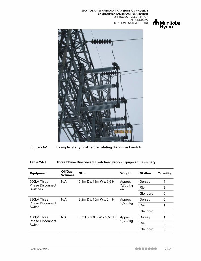
MANITOBA – MINNESOTA TRANSMISSION PROJECT ENVIRONMENTAL IMPACT STATEMENT
2: PROJECT DESCRIPTION APPENDIX 2A:
STATION EQUIPMENT LIST
Figure 2A-1 Example of a typical centre rotating disconnect switch
Table 2A-1 Three Phase Disconnect Switches Station Equipment Summary
Equipment Oil/Gas Volumes Size Weight Station Quantity
500kV Three Phase Disconnect Switches
N/A 5.8m D x 18m W x 9.6 H Approx. 7,730 kg ea.
Dorsey 4
Riel 3
Glenboro 0
230kV Three Phase Disconnect Switch
N/A 3.2m D x 10m W x 6m H Approx. 1,530 kg
Dorsey 0
Riel 1
Glenboro 6
138kV Three Phase Disconnect Switch
N/A 6 m L x 1.8m W x 5.5m H Approx. 1,682 kg
Dorsey 1
Riel 0
Glenboro 0
September 2015 2A-1

MANITOBA – MINNESOTA TRANSMISSION PROJECT ENVIRONMENTAL IMPACT STATEMENT PROJECT DESCRIPTION APPENDIX 2A: STATION EQUIPMENT LIST
Figure 2A-2 Example of a typical 115 kV circuit breaker
Table 2A-2 Circuit Breaker Station Equipment Summary
Equipment Oil/Gas Volumes Size Weight Station Quantity
500kV, 4000A Three Phase Circuit Breaker
Insulating gases 66kg SF6 & 12+kg CF4.
10.8m H x 18m W Approx. 17,508 kg
Dorsey 1
Riel 1
Glenboro 0
230kV, Three Phase Circuit Breaker
12.4kg SF6 & 11.9kg CF4 ea. insulating gas.
8.2m W x 7.6m H Approx. 2,760 kg ea.
Dorsey 0
Riel 1
Glenboro 2
2A-2 September 2015

MANITOBA – MINNESOTA TRANSMISSION PROJECT ENVIRONMENTAL IMPACT STATEMENT
2: PROJECT DESCRIPTION APPENDIX 2A:
STATION EQUIPMENT LIST
Figure 2A-3 Example of a typical current transformer (See Table 3)
September 2015 2A-3

MANITOBA – MINNESOTA TRANSMISSION PROJECT ENVIRONMENTAL IMPACT STATEMENT PROJECT DESCRIPTION APPENDIX 2A: STATION EQUIPMENT LIST
Figure 2A-4 Example of a typical voltage transformer (See Table 3)
2A-4 September 2015

MANITOBA – MINNESOTA TRANSMISSION PROJECT ENVIRONMENTAL IMPACT STATEMENT
2: PROJECT DESCRIPTION APPENDIX 2A:
STATION EQUIPMENT LIST
Figure 2A-5 Example of a typical autotransformer
Table 2A-3 Transformer Station Equipment Summary
Equipment Oil/Gas Volumes Size Weight Station Quantity
500kV Single Phase Current Transformers
662 litres of insulating oil per current transformer.
6.2m H x 1.2m W Approx. 2,176 kg ea.
Dorsey 3
Riel 3
Glenboro 0
500kV Single Phase Capacitor Voltage Transformers
80 litres of insulating oil per capacitor.
5.5m H x .8m W Approx. 566 kg ea.
Dorsey 4
Riel 3
Glenboro 0
500/230/46kV, 400MVA Single Phase Auto Transformers
112,230 litres of insulating oil per unit.
16m L x 9m W x 10m H
Approx. 294,760 kg ea.
Dorsey 0
Riel 3
Glenboro 0
230kV, Single Phase Current Transformers
295 litres of insulating oil per unit.
.9m W x 3m H Approx. 1,029 kg ea.
Dorsey 0
Riel 3
Glenboro 6
September 2015 2A-5

MANITOBA – MINNESOTA TRANSMISSION PROJECT ENVIRONMENTAL IMPACT STATEMENT PROJECT DESCRIPTION APPENDIX 2A: STATION EQUIPMENT LIST
Equipment Oil/Gas Volumes Size Weight Station Quantity
138-115/69kV Capacitor Voltage Transformers
88 litres of insulating oil
1.9m H x .51m W Approx. 442 kg Dorsey 0
Riel 1
Glenboro 0
46kV Single Phase Capacitor Voltage Transformers
50 litres of insulating oil per unit.
5.2m L x 10m W x 8m H
Approx. 261 kg ea.
Dorsey 0
Riel 3
Glenboro 0
2A-6 September 2015

MANITOBA – MINNESOTA TRANSMISSION PROJECT ENVIRONMENTAL IMPACT STATEMENT
2: PROJECT DESCRIPTION APPENDIX 2A:
STATION EQUIPMENT LIST
Figure 2A-6 Example of a typical metal oxide varistor (MOV) surge arrester
Table 2A-4 Single Phase Surge Arrester Station Equipment Summary
Equipment Oil/Gas Volumes Size Weight Station Quantity
500kV Single Phase Surge Arresters
N/A 5.4m H x 1m W Approx. 400 kg ea.
Dorsey 3 Riel 0 Glenboro 0
138kV Single Phase Surge Arrester
N/A 2.5m H x .6m W Approx. 150 kg Dorsey 3 Riel 0 Glenboro 0
46kV Single Phase Surge Arresters
N/A 1.2m x .2m W Approx. 35 kg ea. Dorsey 0 Riel 3 Glenboro 0
September 2015 2A-7
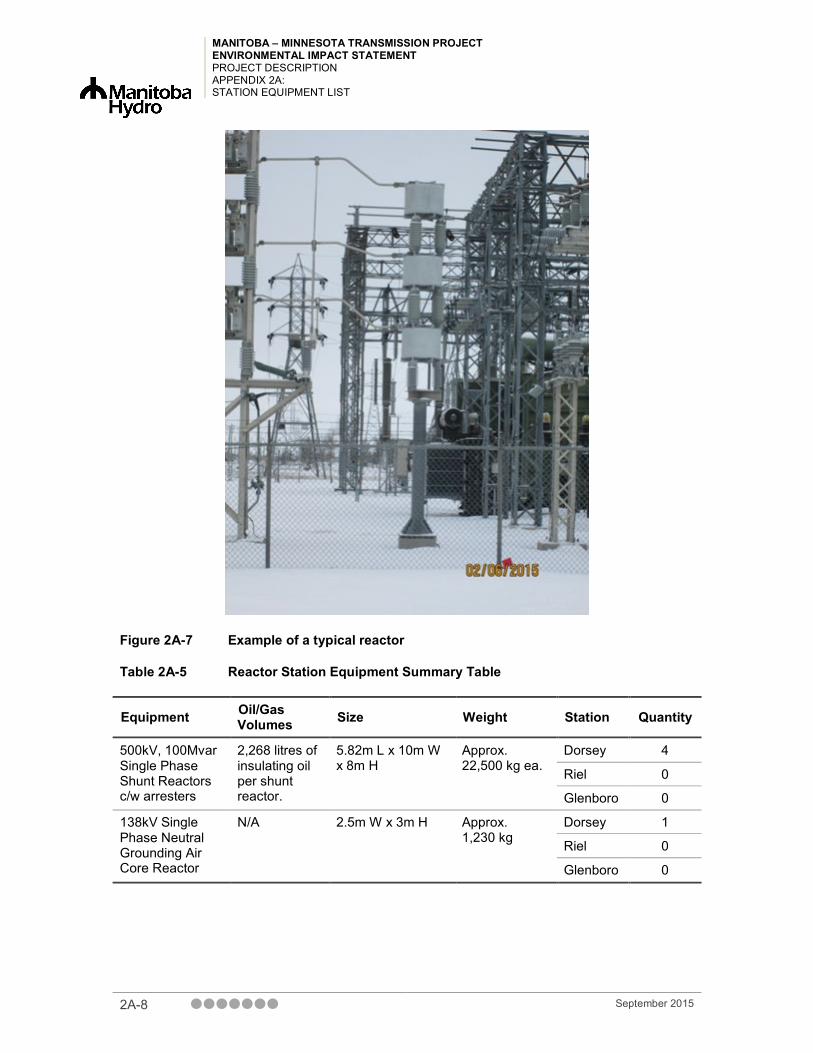
MANITOBA – MINNESOTA TRANSMISSION PROJECT ENVIRONMENTAL IMPACT STATEMENT PROJECT DESCRIPTION APPENDIX 2A: STATION EQUIPMENT LIST
Figure 2A-7 Example of a typical reactor
Table 2A-5 Reactor Station Equipment Summary Table
Equipment Oil/Gas Volumes Size Weight Station Quantity
500kV, 100Mvar Single Phase Shunt Reactors c/w arresters
2,268 litres of insulating oil per shunt reactor.
5.82m L x 10m W x 8m H
Approx. 22,500 kg ea.
Dorsey 4
Riel 0
Glenboro 0
138kV Single Phase Neutral Grounding Air Core Reactor
N/A 2.5m W x 3m H Approx. 1,230 kg
Dorsey 1
Riel 0
Glenboro 0
2A-8 September 2015

MANITOBA – MINNESOTA TRANSMISSION PROJECT ENVIRONMENTAL IMPACT STATEMENT
2: PROJECT DESCRIPTION APPENDIX 2A:
STATION EQUIPMENT LIST
Figure 2A-8 Example of a typical phase shifter transformer
Source: http://www.energy.siemens.com/
Table 2A-6 Phase Shifter Transformer Summary Table
Equipment Oil/Gas Volumes Size Weight Station Quantity
230kV, 300MVA Three Phase, Phase Shifter Transformer
150,000 litres insulating oil each
16m L x 9m W x 10m H Approx. 450,000 kg ea.
Dorsey 0
Riel 0
Glenboro 2
September 2015 2A-9

MANITOBA – MINNESOTA TRANSMISSION PROJECT ENVIRONMENTAL IMPACT STATEMENT PROJECT DESCRIPTION APPENDIX 2A: STATION EQUIPMENT LIST
Figure 2A-9 Example of a typical wave trap
Source: technosources.blogspot.com
2A-10 September 2015

MANITOBA – MINNESOTA TRANSMISSION PROJECT ENVIRONMENTAL IMPACT STATEMENT
2: PROJECT DESCRIPTION APPENDIX 2A:
STATION EQUIPMENT LIST
Figure 2A-10 Example of a typical circuit switcher
Table 2A-7 Equipment to be Relocated within Station Boundaries
Equipment Quantity
230kV Single Phase Surge Arresters 3
230kV Single Phase Voltage Transformers 3
Wave Traps 3
1 -230kV, Circuit Switcher 1
230kV 25MVAR Reactor 1
230kV Three Phase Disconnect Switch c/w Ground Switch 1
September 2015 2A-11