Managing Installation Tolerances through System … Installation Tolerances through System ......
16
26 th Annual INCOSE International Symposium (IS 2016) Edinburgh, Scotland, UK, July 18-21, 2016 Managing Installation Tolerances through System Modeling and Tolerance Budgeting Thomas Henanger Aker Solutions [email protected] Gerrit Muller HSN-NISE [email protected] Luca Piciaccia Aker Solutions [email protected] Copyright © 2016 by Thomas Henanger, Gerrit Muller and Luca Piciaccia. Published and used by INCOSE with permission. Abstract. Contractors in the oil and gas industry are facing challenges when installing subsea production systems (SPS) in deep waters. The installation relies on engineering of the systems with high accuracy levels and narrow clearances on the interfacing surfaces to meet required installation tolerances. To ensure that all installation tolerances requirements are met, there is a need for a systematic governing process of managing, controlling, and verifying them. Engineers define installation tolerances through qualification activities of components and technologies. Extensive systems and complex installation sequences generate tolerance chains affecting the interfacing components. The verification of the installation consequently requires a significant effort. The research focus is on how system modeling and tolerance budgeting would help the process of managing installation tolerances of a subsea production system in the context of preventing late verification, potential late design changes, and errors in installation. Use of system modeling made it possible to visualize the installation of the system of interest, and systematically structure relevant information. The visualization supported the researchers to develop an understanding of the tolerance chain for the system of interest. Based on the models, we were able to put together a tolerance budget calculating the theoretical worst-case scenario of installation on a chosen critical misalignment. Our research showed that the systems engineering (SE) effort had a positive impact on the process, considering the cost of the effort relative to the potential cost of the preventable scenarios. Introduction Domain. Modern offshore oil and gas production includes increasingly complex subsea systems. The evolution of the technology allows the oil companies to move into deeper waters and harsher environments. There are multiple factors affecting the development for a specific field, such as oil or gas field, reservoir pressure and temperature, reservoir depth, water depth, soil conditions, field location, and the existing infrastructure of the field. The engineers consider all these characteristics to ensure that the system will operate as intended. Because of the water depths, the engineers need to install the subsea equipment remotely, using cranes on vessels and rigs. When the engineers install the equipment subsea, they use Remotely Operated Vehicles (ROVs) to monitor and help assembling the modules. If an installation fails, the operators could potentially suffer major economic losses. Common components of a subsea production system are (see Figure 1):
Transcript of Managing Installation Tolerances through System … Installation Tolerances through System ......
26th Annual INCOSE International Symposium (IS 2016)
Edinburgh, Scotland, UK, July 18-21, 2016
Managing Installation Tolerances through System Modeling and Tolerance Budgeting
Thomas Henanger
Aker Solutions
Gerrit Muller
HSN-NISE
Luca Piciaccia
Aker Solutions
Copyright © 2016 by Thomas Henanger, Gerrit Muller and Luca Piciaccia. Published and used by INCOSE with permission.
Abstract. Contractors in the oil and gas industry are facing challenges when installing subsea
production systems (SPS) in deep waters. The installation relies on engineering of the systems
with high accuracy levels and narrow clearances on the interfacing surfaces to meet required
installation tolerances. To ensure that all installation tolerances requirements are met, there is a
need for a systematic governing process of managing, controlling, and verifying them.
Engineers define installation tolerances through qualification activities of components and
technologies. Extensive systems and complex installation sequences generate tolerance chains
affecting the interfacing components. The verification of the installation consequently requires
a significant effort.
The research focus is on how system modeling and tolerance budgeting would help the process
of managing installation tolerances of a subsea production system in the context of preventing
late verification, potential late design changes, and errors in installation. Use of system
modeling made it possible to visualize the installation of the system of interest, and
systematically structure relevant information. The visualization supported the researchers to
develop an understanding of the tolerance chain for the system of interest. Based on the models,
we were able to put together a tolerance budget calculating the theoretical worst-case scenario
of installation on a chosen critical misalignment. Our research showed that the systems
engineering (SE) effort had a positive impact on the process, considering the cost of the effort
relative to the potential cost of the preventable scenarios.
Introduction
Domain. Modern offshore oil and gas production includes increasingly complex subsea
systems. The evolution of the technology allows the oil companies to move into deeper waters
and harsher environments. There are multiple factors affecting the development for a specific
field, such as oil or gas field, reservoir pressure and temperature, reservoir depth, water depth,
soil conditions, field location, and the existing infrastructure of the field. The engineers
consider all these characteristics to ensure that the system will operate as intended. Because of
the water depths, the engineers need to install the subsea equipment remotely, using cranes on
vessels and rigs. When the engineers install the equipment subsea, they use Remotely Operated
Vehicles (ROVs) to monitor and help assembling the modules. If an installation fails, the
operators could potentially suffer major economic losses.
Common components of a subsea production system are (see Figure 1):
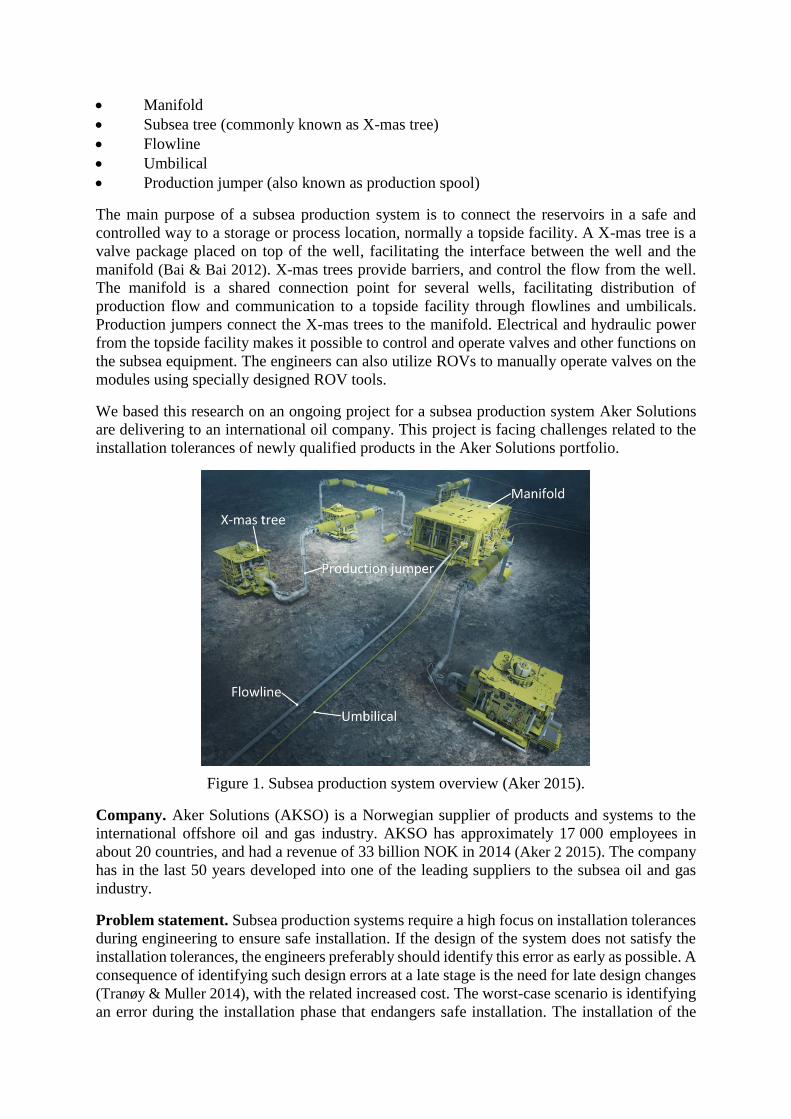
Manifold
Subsea tree (commonly known as X-mas tree)
Flowline
Umbilical
Production jumper (also known as production spool)
The main purpose of a subsea production system is to connect the reservoirs in a safe and
controlled way to a storage or process location, normally a topside facility. A X-mas tree is a
valve package placed on top of the well, facilitating the interface between the well and the
manifold (Bai & Bai 2012). X-mas trees provide barriers, and control the flow from the well.
The manifold is a shared connection point for several wells, facilitating distribution of
production flow and communication to a topside facility through flowlines and umbilicals.
Production jumpers connect the X-mas trees to the manifold. Electrical and hydraulic power
from the topside facility makes it possible to control and operate valves and other functions on
the subsea equipment. The engineers can also utilize ROVs to manually operate valves on the
modules using specially designed ROV tools.
We based this research on an ongoing project for a subsea production system Aker Solutions
are delivering to an international oil company. This project is facing challenges related to the
installation tolerances of newly qualified products in the Aker Solutions portfolio.
Figure 1. Subsea production system overview (Aker 2015).
Company. Aker Solutions (AKSO) is a Norwegian supplier of products and systems to the
international offshore oil and gas industry. AKSO has approximately 17 000 employees in
about 20 countries, and had a revenue of 33 billion NOK in 2014 (Aker 2 2015). The company
has in the last 50 years developed into one of the leading suppliers to the subsea oil and gas
industry.
Problem statement. Subsea production systems require a high focus on installation tolerances
during engineering to ensure safe installation. If the design of the system does not satisfy the
installation tolerances, the engineers preferably should identify this error as early as possible. A
consequence of identifying such design errors at a late stage is the need for late design changes
(Tranøy & Muller 2014), with the related increased cost. The worst-case scenario is identifying
an error during the installation phase that endangers safe installation. The installation of the

system on the seabed normally requires multiple vessels and rigs, which are often on a tight
schedule. This is an exceptionally expensive phase for the operators. An error in installation
tolerances, which stops the installation, would cause delay in schedules and serious cost
impacts. The potential consequences of errors in installation tolerances, demands a thorough
process of managing and verifying them during early engineering phases.
The intention of this research is to develop a method for handling installation tolerances during
early engineering. If the results meet the goal, a long-term objective is that this method could
be part of a standard process of managing tolerances in AKSO.
We focus on system modeling and tolerance budgeting as tools for managing and verifying
installation tolerances of components in a subsea production system. The target is to see the
value of such approaches in the context of preventing late changes in design and errors in
installation. We use the following research questions:
Will experienced personnel accept models and tolerance budget as credible
verification?
Do models and tolerance budgets provide the required knowledge for an engineer
familiar with the system of interest to understand the tolerance view?
Research Methodology
We carried out the research with a combination of industry-as-laboratory (Potts 1993) and
action based research as approaches (Muller 2013). The research methodology is to implement a
systems engineering effort on a process for the system of interest, and identify the effect the
effort had on the process. As part of the research, we investigated the current state of tolerance
management in the company to identify best practices and tools in use. We performed in-depth
interviews with qualified personnel to develop a full picture of the tolerance processes.
After performing the systems engineering effort, we analyzed the outcome to see positive and
negative aspects concerning:
Time spent
Complexity of process
End result
System of Interest
The project we based the research on, is a subsea production system for oil production at more
than 1350 meters water depth off the coast of Angola. The development includes a newly
developed satellite vertical X-mas tree. The X-mas trees are clustered within a radius of 20
meters from a manifold module, and are tied back to the manifold using production jumpers.
Flowlines and umbilicals connect the manifold to a topside facility.
In modern subsea production systems there are two commonly used X-mas tree concepts:
horizontal X-mas trees and vertical X-mas trees. These two types of trees serve different cost
profile benefits in capital expenditures (CAPEX) and operating expenditures (OPEX).The
essential difference between these two types of trees is that the first barrier valve of the
horizontal tree is located in the horizontal plane, while in vertical trees it is located in the
vertical plane. This is the origin of the names. The production tubing is a pipe installed in the
well facilitating the transport of hydrocarbons from the reservoir to the X-mas tree. The tubing
interfaces to the tree through the tubing hanger.

Another distinguishing factor between the two concepts is that for vertical trees the tubing
hanger is installed in the wellhead, and is therefore installed prior the tree (see Figure 2). This
differs from horizontal trees, where the tubing is installed after the tree, and through the X-mas
tree bore. The installation sequence for the vertical X-mas tree therefore allows the tubing to be
left in the well when the tree is retrieved to the surface for maintenance. The water depth on this
project benefits the vertical X-mas tree, as it provides advantages related to time used when
retrieving the tree. However, as the vertical X-mas tree is a newly developed component in
AKSO, it involves a new installation sequence.
Figure 2. Simplified installation sequence of satellite vertical X-mas tree system.
The production jumper, which provides the interface between the vertical X-mas tree and the
manifold, consists of a rigid pipe facilitating production flow, as well as hydraulic lines to
operate valves and functions on the tree and in the well. When the jumper is installed, it is first
landed on a jumper landing frame which is fixed to the permanent guide base (PGB) (see
Figure 2). When landing the vertical X-mas tree subsea, the interface towards the tubing hanger
provides the orientation of the tree. The orientation of the tubing hanger inside the wellhead,
and the installation sequence leading to it, therefore determines the final heading of the X-mas
tree hub towards the jumper landing frame. After both the X-mas tree and the jumper are in
place, the X-mas tree hub and jumper are stroked together to connect. As the tubing hanger
determines the X-mas tree orientation and not the PGB, the tree theoretically could become
misaligned towards the landing frame and the jumper (see Figure 3).
The jumper requires the X-mas tree hub to be within a certain angle of alignment according to
the landing frame to be able to connect. If the required alignment is not met, one cannot

perform tie-in operation without risking damage to the equipment. Such a scenario would
block installation. Depending on the seriousness of the misalignment, potential damage of
equipment, and the required procedure for re-work to achieve desired alignment, it could take
weeks or months before the re-work is completed. Figure 3 shows the top view of the X-mas
tree, the PGB and the jumper. At the left picture we can see that the tree is aligned towards the
jumper, at the right it is misaligned.
Figure 3. Top view of vertical X-mas tree aligned and misaligned.
Current way of managing tolerances
We can divide tolerances into two main categories; machining and fabrication tolerances, and
installation tolerances. Designers define the machining and fabrication tolerances of
components when developing drawings. These drawings normally come from calculations and
experience on what is possible and required to manufacture, as well as industry standards. The
machining and fabrication tolerances are largely standardized. AKSO pursues standardization
to ensure quality of the products. In AKSO projects there are several product groups who
deliver different parts of the system. Every product group handles their machining and
fabrication tolerances individually. It is a different case with installation tolerances. These are a
shared responsibility between the product groups through the interface management process in
a project.
There are several different terms in use related to the process around tolerances. A central term
is qualification, which refers to the process of approving new technology. The qualification of
a new product consists of a set of required activities prior to implementing new technology in a
system, defined by DNV-RP-A203 (DNV 2013). All AKSO qualifications follow a technology
qualification program (TQP).
All qualified components have a defined envelope for safe installation. The product groups
define these envelopes through the qualification process, based on the maximum misalignment
the component can handle to be able to install it. The engineers need to verify all installation
cases, which is another essential term. In a systems engineering perspective, verification
comprises checking that the product is correct according to the requirements (BKCASE 2016).
To verify installation of a component, the envelopes of interfacing components need to match.
The verification process of installation tolerances is therefore central in our case.
When assembling components together there is always a certain amount of margin/clearance
between them. Some clearance is generally necessary to ensure that two components mate
correctly. In large assemblies, where there is clearance in every interface, the installation
tolerances are affected, and they form tolerance chains. Consequently, interfacing components
affect the installation envelopes. This issue is highly relevant in subsea systems, as the
engineers install the components remotely on the seabed, without direct feedback from the

internals of the system. Verification of installation tolerances of subsea production systems is
therefore a complex process.
The product groups have different practices, philosophies, and tools when verifying
installation tolerances. Tools in this context include different methods and techniques, which
the engineers apply in the process of managing tolerances. In complex tolerance chains, such as
the system of interest, it is increasingly common practice to use computer-aided software. With
computer-aided tools, the engineers have the opportunity to employ statistical analysis, which
includes the likelihood of a worst-case scenario installation. Probability is useful in some cases
to be able to verify installation. Utilization of such tools is time consuming process, and
requires trained personnel.
Use of tolerance budgets as a tool to verify tolerances exist to some extent in various
approaches in AKSO, but not under a governing procedural umbrella. Different product groups
have developed Excel-based tolerance budgets for specific components and interfaces. These
budgets are relatively well developed, and are useful in the individual cases. However, they
might be hard to understand without proper training. Obtaining the relevant information from a
tolerance budget could cause difficulties for an engineer not familiar with the components and
budget structure. Understanding of such budgets is essential for systems engineers to evaluate
the possibilities and limitations of a component.
A different term important in this case, is validation (BKCASE 2016). Validation in the context
of this research should ensure that the verification tool sufficiently reflects reality, hence, that
the tool does not contain errors. If a tool is not valid, it cannot be trusted. For example, the
engineers need to validate a budget to ensure no errors exist. If the budget in this example is
missing contributing factors, which affect the alignment, the budget is invalid.
In standardized subsea systems, this verification process of tolerances normally is not
considered a critical issue. The product groups have well established routines and experience in
how to cope with installation on known systems. However, more demanding needs from the
customers drive development and qualification of new components, which leads to new
installation cases.
Figure 4. V-model (FHWA).
When oil companies are developing a new oil or gas field, relevant contractors receive an
invitation to tender (ITT). When the contractors deliver the project tender, they specify any

new components and qualifications needed for the delivery, which is not in the existing
qualified portfolio. The contractors then also provide a classification of the technology
readiness level (TRL) (NASA 2012) of the new product. Selling a product not fully qualified is
a risk the contractors need to take. If AKSO wins a contract for an unqualified product, the
qualification activities are performed in parallel with the project execution. This also includes a
certain risk related to tolerances, as the project likely has entered high-level or detailed design
before the tolerance verification process is complete. Figure 4 illustrates the SE V model, and
the red circle indicates the current phase of qualification and tolerance verification of new
products in AKSO projects. If the installation tolerance verification fails during project
execution, it is normally costly to implement changes necessary to satisfy the tolerance
verification.
In our case, the engineers perform the qualification of the vertical X-mas tree during a project,
and the installation tolerances are therefore verified in parallel.
In this research, we use managing as an umbrella-term for all activities and processes related to
verifying installation tolerances.
Systems Engineering Literature and Application
Late verification of design in a project could consequently lead to late changes and errors
during testing, installation and operation. The cost of committed changes in a system escalates
over time during a development/project (see Figure 5) (Haskins 2011), and this points out the
importance of verification and validation activities, as described by the V-model (FHWA). The
risk of increased cost is significant without proper verification and validation activities, and the
consequences escalate as the system approaches to operation.
Figure 5. Committed Life-cycle Cost against Time (Haskins 2011).
System modeling. Modeling is one of the core techniques in Systems Engineering (Muller
2014). Engineers use modeling and simulation on complex projects to manage uncertainty and
the risk of failure, and to ensure meeting performance requirements and system mission
(Haskins 2011). System modeling facilitates amongst others communication, discussion,
exploration, and validation of system specification and design. Modeling provides a systematic
overview of a system architecture and application, and has a large area of use. Modern complex
engineered systems, such as subsea systems, often consist of numerous components with their
related disciplines and interfaces. Visualizing a system in the early stage of development is

beneficial for providing the in-depth understanding of areas of application, such as
manufacturing, installation, operation, maintenance and disposal (BKCASE 2016). Modeling
provides the life cycle view of the system. Especially critical integration operations are highly
relevant to model. Detailing the system characteristics in an organized manner helps identify
unknown aspects, or aspects not considered crucial for design, which might affect the way
forward. In a systems engineering perspective, modeling is a central tool alongside utilizing
other systems engineering techniques.
Preferably, modeling should start as early in the process as possible (BKCASE 2016). However,
there may be need for different types of models at different stages of a project life cycle.
System modeling has many different approaches, and it is essential to select the visualization
tool and philosophy best applicable in each case. One of the first principles is defining the
purpose of the model early. A key guideline is to include only the information necessary
(Haveman 2014). This will keep the model as simple as possible. There is also required a certain
validation of a system model to check that it correctly reflects the system characteristics. An
incorrect model does not serve the intended purpose.
Figure 6 shows an example of a system model. This model visualizes the architecture, relative
size, and interfaces of main components of a subsea production system. Simple models like this
have the benefit of describing the conceptual design of a system. In this case, for example, the
model could help understanding and explain the installation order of the system.
Figure 6. System modeling example of a subsea production system.
Budgeting. Budgeting is an expression most commonly known in economic terms. However,
budgeting can also be utilized in allocation of other kind of resources. In engineering,
budgeting is a valuable tool to distribute resources, which are essential to the design, in the best
possible way (Muller 2006) (BKCASE 2016). Budgeting is the process of collecting and
structuring information about the resource, and distributing this throughout a decomposition of
the system. As Freriks et al. (2006) state, use of budgets during design has several benefits
(Muller 2006):
To make the design more explicit.
To provide a baseline for taking design decisions.
To specify the requirements for the detailed design of the components.
To have guidance during integration.
To be a baseline for verification.
To manage the design margins explicitly.

Systems Engineering Approach for System of Interest
Choices of research area. We chose to focus the research on the alignment of the X-mas tree
hub relative to the production jumper. This is a critical interface in the installation phase of the
system of interest. The jumper has a defined envelope of tolerances for safe installation along
six degrees of freedom. This envelope limits the maximum misalignment the X-mas tree hub
can have to be able to install the jumper. Engineers consider the angular misalignment along
the z-axis one of the most critical misalignments (see Figure 2 and 3). The reason is that the
final guiding of the X-mas tree is performed close to the well center. The distance between the
well center and the hub face (see Figure 3) then generates a gearing-effect, which provides a
major contribution on misalignment for the heading of the X-mas tree. Therefore, we
concentrated the research on the worst-case scenario angular misalignment along the z-axis
accumulated by the clearances through the installation, which finalizes at the interface between
the X-mas tree and the tubing hanger. To visualize the contributing interfaces, we defined them
with node numbers, which we preserved through the models and the budget.
The philosophy of the research was to provide overview and understanding of the system
installation and related tolerance chains generated through the system installation.
System model of installation. To provide the required understanding and overview of the
system as a whole, we developed a system model, detailing the installation sequences. The
model contains a total of 23 slides. Each slide visualizes a relevant installation step and a
description of the related activities, interfaces, references, and other affecting factors.
Figure 7. Extract from system model of installation sequences.
We made the level of detail in the visualization sufficient to create a red thread for
understanding the different parts affecting each other. We also included drawings in addition to

the models, showing the actual design and dimensions of the components most essential for
each step. We referred to relevant documentation where it was necessary. We used MS Visio as
tool to create the models, as this was the most suitable and convenient in our case. Figure 7
shows an extract of the model at two different stages of the installation. Slide 11 and 12 shows
tubing hanger installation and slide 17 and 18 shows X-mas tree installation. The system model
contributed an understanding of what stages, components, and interfaces that are contributing
to the misalignment along the z-axis. These factors all had an impact on the tolerances in one or
several stages of the installation. By collecting this information into a block diagram (see
Figure 8), the tolerance chain through the system appeared. The relevant documentation
provided deeper knowledge of these chains. The block diagram gives an overview of the two
main subsea installation phases, which determine the orientation of the X-mas tree. These two
phases are the tubing hanger installation and the X-mas tree installation. The block diagram
helped understanding the relevant few interfaces that are contributing most to the z-axis
misalignment. The green nodes in the block diagram indicate these interfaces. Every square
box represents a component or sub-component taking part in the installation.
Figure 8. Tolerance chain block diagram.
Tolerance budget. During the research, we interviewed AKSO personnel with experience
within tolerances management and verification. Existing tolerance budgets inspired layouts,
structure, and methodology for how to construct the tolerance budget.

Figure 9. Layout and extract of the tolerance budget.
The budget gives a definition of every interface with dimensions, and calculation of clearances
and the maximum angular outcome of them. We maintained the references to documentation
and images of the interfaces to facilitate understanding for personnel not familiar with the
system. A summation of the possible angular displacement for each component gave the total
angular misalignment. Figure 9 shows the layout of the full budget, and an extract showing the
calculations for node 1. Each of the six researched nodes has a similar calculation.
Results and Analysis
Research questions. As stated in the introduction, we used the following research questions to
evaluate the models and tolerance budget:
Will experienced personnel accept models and tolerance budget as credible
verification?
Do models and tolerance budgets provide the required knowledge for an engineer
familiar with the system of interest to understand the tolerance view?
Throughout the research, we performed a validation process with experienced engineers to
evaluate the credibility of the approach. The validation process shows that, with the chosen
scope limitations of the research, the models and tolerance budget are fit-for-purpose, and are
within the required credibility. This means that the engineers accepted the models and budget
for the purpose of the use.
For the purpose of producing the models and tolerance budget within the required detail level,
we researched through the validation process if the models and tolerance budget provided the
required knowledge about the tolerance view. With certain explanation from the researchers,
the tolerance view became clear for the involved engineers. However, a common subject in the
feedback was that using active links within the documentation could be beneficial for the
research in the sense of connecting the models and tolerance budget more together. This would
ease the process of understanding the philosophy and terminology of the produced documents.
During research, we observed the time spent on the activity, the complexity of the process, and
the end result outcome of the effort.

Time spent. The modeling part of the systems engineering effort was, in our case, a relatively
quick process. One systems engineer developed the base of the model within 2 weeks of work.
Concentrating the modeling on integration phases leading to the end orientation of the X-mas
tree hub, we could limit the amount of information and model slides to the essential steps. The
most time-consuming part of the modeling was obtaining the relevant information of each
component. The newly qualified X-mas tree had no available installation procedures.
Consequently, we needed to obtain the information from other sources. We consulted
experienced engineers when gathering the information needed to complete the model within
the required detail level. When the system model was completed, constructing the block
diagram was a relatively easy activity, as that all the critical interfaces already were identified.
We built the tolerance budget layout and gathered dimensions through the referenced
documentation in the system model, which speeded the process.
Figure 10. Time line for the systems engineering effort.
The process of gathering required information was the most time consuming activity, and
continued almost throughout the whole research (see Figure 10). However, as we identified the
main sources to this information, the activity became more efficient. The progress on the
systems engineering effort was occasionally inefficient as an effect of the lack of knowledge
about the system of interest amongst the researchers. However, prerequisite of a certain level of
experience would increase the efficiency of the process. The total amount of time spent on the
effort was approximately 13.5 person weeks.
Complexity of process. As the system of interest contains a number of product groups and
components, involvement of several stakeholders was required throughout the process. We
performed a validation of each part as a final activity before moving to the next (see Figure 10).
We discovered that the personnel from the different product groups had significant differences
in opinions on the subject. In addition, differences in experience within tolerance management
and the system of interest among stakeholders caused challenges in differentiating the value of
their opinions.
The interviews also identified different views among the personnel regarding the value of our
systems engineering effort, as well as the general methodology of tolerance management. Such
could lead to doubt concerning the validity of the effort.
There will always be more than one point of view in cases such as the subject of the research,
which in our case was challenging to analyze. As tolerance management in AKSO includes
several aspects (machining, fabrication, and installation tolerances), it was sometimes difficult
to speak the same tolerance language with the interviewed personnel. The definition of
tolerances has different meanings in the different product groups.

Subsea production systems have a certain level of complexity in themselves, and maintaining
the system view whilst discussing details requires a certain level of knowledge and experience.
End result. The tolerance budget shows that the X-mas tree theoretically can get a maximum
angular misalignment along the z-axis which is within the envelope limitations, generated by
the contributing factors considered in the research. By this, we verified that the current design
and insight in design resulted in the desired tolerance.
Discussion
The budget provided the theoretically maximum angular misalignment of the X-mas tree
generated by the researched interfaces. Due to the validation processes with involvement of
experienced engineers, which confirmed the data provided by models and budget, we are
confident that the outcome result reflects reality.
The complexity of the process, with the related activities and gathering the required
information from stakeholders, had a clear impact on the time spent. Our interpretation is that
the level of knowledge about the system of interest, as well as the knowledge of the systems
engineering approach, affected the efficiency of the research greatly. An assumption is that if a
systems engineer is to perform a similar research in the future, lessons learned from this
research will speed the process.
We predict that a similar process for a new system would be approximately 2 months’ work for
one systems engineer, assuming reasonable knowledge. This gives the following cost estimate:
Estimated time Cost per engineering hour for operator
Estimated cost of effort for one engineer
Estimated cost of effort including involvement of additional resources
~2 months = 315 h ~1 000 NOK ~315.000 NOK ~350.000 NOK
If there is an error in installation tolerances of the system, there are many different scenarios,
depending on what project phase the error is identified, and the scope of the error. As Figure 5
describes, the committed cost increases in time of the life cycle. Postponing verification of
essential design characteristics, such as installation tolerances, has potentially major effects on
the life cycle cost.
A tolerance error identified during installation phase, which stops the installation, is the
worst-case scenario. This could potentially delay overall installation schedule and expected
production start-up. If for example installation is delayed 1 week, it could generate the
following cost for one offshore installation vessel:
Estimated minimum time before error is fixed
Day rate for one installation vessel
Estimated cost per week delay
~1 week = 7 days ~2.0 MNOK/day ~14.0 MNOK
We see that 1 week delay in installation with a daily vessel rate of 2.0 MNOK (varying due to
market interest) accumulates cost of 14.0 MNOK. We consider only 1 week of delay an
optimistic estimate, as an error in installation could cause sever ripple effects for the operator.
In addition to the 1-week vessel cost, the delay could cause other rigs and/or vessels on standby
until error is fixed. Such a case would generate losses of a more serious scale.
A general assumption is that such an error would/should be identified prior installation, likely
at least during system integration testing. However, cost impacts increase throughout project
phase, and a tolerance error have the potential of causing significant delay and cost impact
already early in project.
Conclusion
Our interpretation of the outcome of this research is that the systems engineering effort had a
positive impact on the process of managing installation tolerances. Seeing the result in context
of preventing late verification of tolerances and possible late changes and errors during
installation indicates that the effort has a value. The cost of such an effort is, in AKSO’s case,
insignificant relative to the cost accumulated by the preventable scenarios.
We think that the effort has, among others, a clear benefit in developing understanding and
identifying critical integration steps of a system. An example is, that by using this technique as
a screening-method at an early stage (before contract award), would help identify critical
aspects where there is need for further investigation, and which possibly could trigger
necessary design changes. Limited knowledge about the system tolerance view among
respective product groups increases the risk not meeting tolerance requirements. Having one
systems engineer coordinating the tolerance management from the start, with support from
dedicated engineers in the product groups, may aid the process of developing a well-integrated
system at the end.
Future research
Throughout our research, we learned that subsea production systems projects are verifying
installation tolerances in the high-level and/or detailed design phases of a project. A more
sustainable proof on the validity of the tolerance design is preferred to mitigate the risk of
failure. System models and tolerance budgets will help exposing the characteristics of a system,
but will never overrule the actual system in operation. The issues that tolerances provide when
installing subsea systems needs to be solved, and more tolerance focused testing of the systems
might be a part of this solution.
There is need for more research on how the increasingly complex tolerance challenges can be
mitigated in the future to prevent late design changes and failures in installation.
References
Aker Solutions First-Quarter Results 2015. Accessed 05.12.2015.
http://www.akersolutions.com/Documents/Investors/Quarterly%20reports/2015/Aker_Solutions_1Q_2015_quarterly_report.pdf
Aker Solutions web page. Accessed 05.12.2015.
http://www.akersolutions.com/en/Global-menu/About-us/
Bai, Y.; Bai, Q. 2012. “Subsea Structural Engineering Handbook”. Gulf Professional
Publishing.
BKCASE Editorial Board. 2016. The Guide to the Systems Engineering Body of Knowledge
(SEBoK), v. 1.6. R.D. Adcock (EIC). Hoboken, NJ: The Trustees of the Stevens
Institute of Technology. Accessed05.12.3015 www.sebokwiki.org.

Choi, M. 2008. “Contesting Imaginaries in Death Rituals during the Northern Song Dynasty.”
PhD diss., University of Chicago (Chicago, IL, US).
DNV. 2013. “Recommended Practice DNV-RP-A203, Technology Qualification”.
FHWA. “Systems Engineering for Intelligent Transportation Systems”. (05.12.2015)
http://ops.fhwa.dot.gov/publications/seitsguide/section3.htm
Haskins, C., ed. 2011. “Systems Engineering Handbook: A Guide for System Life Cycle
Processes and Activities” Version 3.2.2 Revised by M. Krueger, D. Walden, and R. D.
Hamelin. San Diego, CA (US): INCOSE.
Haveman, S. P.; Bonnema, M.; van den Berg, F. G. B. 2014. “Early insight in systems design
through modeling and simulation”. Conference on Systems Engineering Research
(CSER 2014)
Muller, G. 2013. “Systems Engineering Research Methods, CSER 2013 in Atlanta
Muller, G. 2014. “System Modeling and Analysis” (SEMA 6201). (05.12.2015).
http://www.gaudisite.nl/SEMAmaterial.html
Muller, G.; Freriks, H.; Heemels, M.; Sandee, H. 2006. ”On the Systematic Use of
Budget-Based Design”. Sixteenth Annual International Symposium of the International
Council on Systems Engineering (INCOSE) 8-14 July 2006.
NASA, “Technology Readiness Level”. 2012 Accessed 05.12.2015.
https://www.nasa.gov/content/technology-readiness-level/
Potts, C. 1993. “Software-engineering research revisited”. IEEE Software, Vol. 10, No.
5:19–28, September/October 1993.
Tranøy, E., Muller, G. 2014. 7.1. 1 Reduction of Late Design Changes Through Early Phase
Need Analysis. In INCOSE International Symposium (Vol. 24, No. 1, pp. 570-582).

Biography
Thomas Henanger is a Systems Engineer in Aker Solutions. He has 3
years’ experience from the subsea oil and gas industry. His project
experience includes EPC projects for light well intervention systems
and subsea production systems. He holds a Bachelor degree within
Industrial Engineering from Bergen University College. This paper is
part of the research done for his Master’s degree in Systems
Engineering at Buskerud and Vestfold University College.
Gerrit Muller, originally from the Netherlands, received his Master’s
degree in physics from the University of Amsterdam in 1979. He
worked from 1980 until 1997 at Philips Medical Systems as a system
architect, followed by two years at ASML as a manager of systems
engineering, returning to Philips (Research) in 1999. Since 2003 he
has worked as a senior research fellow at the Embedded Systems
Institute in Eindhoven, focusing on developing system architecture
methods and the education of new system architects, receiving his
doctorate in 2004. In January 2008, he became a full professor of
systems engineering at Buskerud and Vestfold University College in
Kongsberg, Norway. He continues to work as a senior research
fellow at the Embedded Systems Innovations by TNO in Eindhoven
in a part-time position. All information (System Architecture articles,
course material, curriculum vitae) can be found at: Gaudí systems
architecting http://www.gaudisite.nl/
Luca Abele Piciaccia developed his 25+ years systems engineering
career in the Subsea Oil Industry at Major Oil Companies and leading
EPC contractors, where he held several positions as Engineering
Manager, Commissioning Responsible and Department Manager before
becoming Chief Engineer - Subsea Systems Engineering for Major
Subsea Projects. His education includes Nuclear Engineering at the
Technical University in Milano, BSc in Engineering Management at
CCU and an MBA in Technology Management from Chiefly Business
School in Australia. Luca has served 2 terms as president of the
Norwegian INCOSE chapter.
Gerrit Muller
Thomas Henanger
Luca Piciaccia