Management of CADD Title & Description Date
18
Table of Contents Management of CADD Title & Description Date 1. Templates & Prototypes – Installing the AutoCAD templates, Eagle Point prototypes, and CADD support files. 3/22/2005 2. NRCS/EP Menus – Installation of customized NRCS/EP menus & toolbars. 3/22/2005 3. Files & Projects – Tips for management of Eagle Point & AutoCAD files & projects. 9/29/2003 4. Transferring Files – Using Windows Explorer and the CCE servers to transfer CADD files & projects. 9/30/2003 5. License Manager – What to do if a network license is not working correctly. 9/24/2003 Managing CADD i 3/22/2005
Transcript of Management of CADD Title & Description Date

Table of Contents
Management of CADD
Title & Description Date
1. Templates & Prototypes – Installing the AutoCAD templates, Eagle Point prototypes, and CADD support files.
3/22/2005
2. NRCS/EP Menus – Installation of customized NRCS/EP menus & toolbars.
3/22/2005
3. Files & Projects – Tips for management of Eagle Point & AutoCAD files & projects.
9/29/2003
4. Transferring Files – Using Windows Explorer and the CCE servers to transfer CADD files & projects.
9/30/2003
5. License Manager – What to do if a network license is not working correctly.
9/24/2003
Managing CADD i 3/22/2005

Templates & Prototypes
Installation of Midwest CADD standards & Iowa support files Summary of Updates:
• These user support files are set up for use with AutoDesk Map 3D 2005 and Eagle Point 2004 Q4.3.0 products.
• Two options are available for installation of these support files: o 1) “Network”. The files are placed into a network location that is shared and
mapped as a P:\ drive. This can allow updates to blocks, templates, etc without the need to install them on every CAD computer. This does require that the CAD workstation be connected to the mapped network folder.
o 2) “Laptop” or (non-Network). The files are placed on the local C:\ drive in a My NRCS Engineering folder. This eliminates the requirement for connecting to a shared network folder. Any updates to these support files would need to be done on all CAD computers.
• Tables, Sheet sets & Tool palettes are utilized. Title blocks can be filled out using either drawing fields or sheet set fields.
Option 1 - Network Files to Extract to a shared Network location: Network_P\Items for Network Folder\P CADD Resources.exe ♦ Contains – NRCS template and prototype drawings, borders, blocks, OLE items, tables, tool
palettes. ♦ Extract to the network P:\ drive location where the AutoCAD Resource Files will be stored
(CADD Resources\… will be created). Files to Extract to the CAD workstation: Network_P\UserSupport.zip ♦ Contains NRCS support files for linestyles, plot styles, etc ♦ Extract into the folder that holds the user’s Support folder for ACAD. (Mine is c:\Documents
and Settings\{user.name}\Application data\Autodesk\AutoDesk Map3D 2005\R16.1\enu\) For Autodesk Map 3D 2005 products, these files can be extracted into the c:\Program files\Autodesk Map 3D 2005\UserDataCache\ folder and the files will automatically be copied into the user’s Support folder if that user has not previously launched CAD.
Network_P\P EpcadSettings.exe ♦ Contains – Default CAD settings for EaglePoint with an NRCS prototype project.
Two added default prototypes are created (11x17 and 22x34) that will look for the prototype drawings in the P:\CADD Resources\Templates folder. Road calc templates and prototypes will overwrite existing files. Surface Model, Watershed Modeling, and Water Surface Profile libraries will overwrite any existing libraries.
♦ Extract to the EGPT folder that holds the Support folder. (Mine is c:\Program Files\Eagle Point Software\EGPT)
Network_P\IA_FieldCode.exe ♦ Contains - Iowa Field Code node library and data collection settings for use with Eagle Point.
Managing CADD 1 3/22/2005

Templates & Prototypes
♦ NOTE: This will overwrite any existing Field code libraries changes that you have made. Backup your “Support” directory to be able to restore your settings.
♦ Extract to the EGPT folder that holds the Support folder. (Mine is c:\Program Files\Eagle Point Software\EGPT)
Other AutoCAD Profile settings: AutoCAD menu -Tools… Options… Files…
Drawing Template File Location should have P:\CADD Resources\Templates Support File Search Path should have c:\Program Files\Eagle Point Software\EGPT\Images
AutoCAD menu - Tools… Options… Plotting… Default plot style table = monochrome.ctb or IA NRCS BWgray.ctb
(These profile settings are taken care of if you set up the EP/NRCS Customized menus v1.15a.) Option 2 – Laptop (or non-network) Files to Extract to the CAD workstation: Laptop_C\C CADD Resources.exe ♦ Contains – NRCS template and prototype drawings, borders, blocks, OLE items, tables, tool
palettes. ♦ Extract to the workstation C:\ drive location where the AutoCAD Resource Files will be
stored (My NRCS Engineering\CADD Resources\… will be created). Laptop_C\UserSupport.zip ♦ Contains NRCS support files for linestyles, plot styles, etc ♦ Extract into the folder that holds the user’s Support folder for ACAD. (Mine is c:\Documents
and Settings\{user.name}\Application data\Autodesk\AutoDesk Map3D 2005\R16.1\enu\) For Autodesk Map 3D 2005 products, these files can be extracted into the c:\Program files\Autodesk Map 3D 2005\UserDataCache\ folder and the files will automatically be copied into the user’s Support folder if that user has not previously launched CAD.
Laptop_C\P EPcadSettings.exe ♦ Contains – Default CAD settings for EaglePoint with an NRCS prototype project
Two added default prototypes are created (11x17 and 22x34) that will look for the prototype drawings in the C:\My NRCS Engineering\CADD Resources\Templates folder. Road calc templates and prototypes will overwrite existing files. Surface Model, Watershed Modeling, and Water Surface Profile libraries will overwrite any existing libraries.
♦ Extract to the EGPT folder that holds the Support folder. (Mine is c:\Program Files\Eagle Point Software\EGPT)
Laptop_C\IA_FieldCode.exe ♦ Contains - Iowa Field Code node library and data collection settings for use with Eagle Point. ♦ NOTE: This will overwrite any existing Field code libraries changes that you have made.
Backup your “Support” directory to be able to restore your settings. ♦ Extract to the EGPT folder that holds the Support folder.
(Mine is c:\Program Files\Eagle Point Software\EGPT)
Managing CADD 2 3/22/2005

Templates & Prototypes
Other AutoCAD Profile settings: AutoCAD menu -Tools… Options… Files…
Drawing Template File Location should have C:\My NRCS Engineering\CADD Resources\Templates Support File Search Path should have c:\Program Files\Eagle Point Software\EGPT\Images
AutoCAD menu - Tools… Options… Plotting… Default plot style table = monochrome.ctb or IA NRCS BWgray.ctb
(These profile settings are taken care of if you set up the EP/NRCS Customized menus v1.15a.)
Managing CADD 3 3/22/2005


NRCS/EP Menus
Installation of customized NRCS/EP menus & toolbars NRCS/EP Menu & Toolbars – Version 1.15a Extract the files: Extract the contents of EPmmMenu.exe into the folder that contains the AutoCAD program.
Mine is the c:\Program Files\AutoDesk Map 3D 2005 folder. A SupportNRCS folder will be created containing menu files. A SupportNRCS\macros folder will be created containing the macro files.
Steps for each CAD user: Auto setup of menus & macros:
1) Launch Eagle Point & Autodesk Map 3D 2005 and open an Eagle Point project. 2) In AutoCAD go to File…Open… 3) Browse to c:\Program Files\Autodesk Map 3D 2005\Support
NRCS\SetupNRCSmenus.dwg. 4) Click Enable macros. 5) Template folder location
(a) Click Yes for the Iowa Workstation default setup that has the P:\CADD Resources\Templates as the template location.
(b) Or click No for the Iowa Laptop default or for no change. A 2nd dialog box will come up. (i) Click Yes for the Iowa Laptop default setup that has the C:\My NRCS
Engineering\CADD Resources\Templates as the template location . (ii) Or Click No to leave the template location unchanged.
6) Click Ok after noting how your template location has been set. 7) Click File… Exit… and do not save changes to the SetupNRCSmenus.dwg. 8) You will probably get an Autodesk Fatal Error at this point. 9) If so, quit out of both Eagle Point & Autodesk Map.
(a) Launch Autodesk Map 3D 2005 ONLY and make sure the Eagle_Point_98 profile is current.
(b) Repeat steps 2 through 6 (c) Click File… Exit… and do not save changes to the SetupNRCSmenus.dwg.
10) Re-Launch Eagle Point & Autodesk Map 3D 2005 11) Continue with any Tool Palette and tool bar customizations.
The NRCS/EP menu will be added to the menu and 6 toolbars associated with the menu
group EP_NRCS are available. The storage pond, effective fetch, and auxiliary spillway layout, coordinate extractor and other macros will also be available for use.
Summary of Updates: Version 1.15a The SetupNRCSmenu.dwg turns off some of the toolbars that are typically not used. Menu Items Added:
Waterway RoadCalc-> Drafting—Annotate Alignment Survey Import -> Export Data
Managing CADD 1 3/22/2005
NRCS/EP Menus
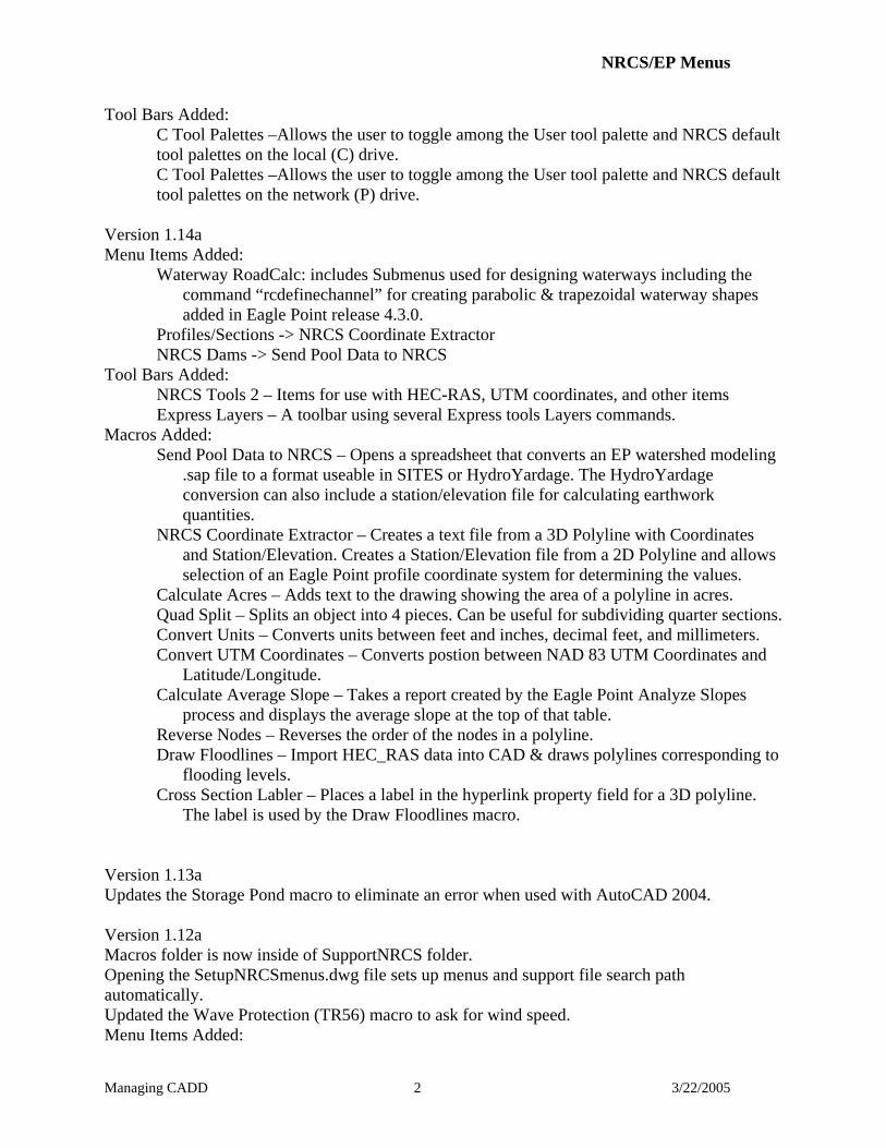
Tool Bars Added: C Tool Palettes –Allows the user to toggle among the User tool palette and NRCS default tool palettes on the local (C) drive. C Tool Palettes –Allows the user to toggle among the User tool palette and NRCS default tool palettes on the network (P) drive.
Version 1.14a Menu Items Added:
Waterway RoadCalc: includes Submenus used for designing waterways including the command “rcdefinechannel” for creating parabolic & trapezoidal waterway shapes added in Eagle Point release 4.3.0.
Profiles/Sections -> NRCS Coordinate Extractor NRCS Dams -> Send Pool Data to NRCS
Tool Bars Added: NRCS Tools 2 – Items for use with HEC-RAS, UTM coordinates, and other items Express Layers – A toolbar using several Express tools Layers commands.
Macros Added: Send Pool Data to NRCS – Opens a spreadsheet that converts an EP watershed modeling
.sap file to a format useable in SITES or HydroYardage. The HydroYardage conversion can also include a station/elevation file for calculating earthwork quantities.
NRCS Coordinate Extractor – Creates a text file from a 3D Polyline with Coordinates and Station/Elevation. Creates a Station/Elevation file from a 2D Polyline and allows selection of an Eagle Point profile coordinate system for determining the values.
Calculate Acres – Adds text to the drawing showing the area of a polyline in acres. Quad Split – Splits an object into 4 pieces. Can be useful for subdividing quarter sections. Convert Units – Converts units between feet and inches, decimal feet, and millimeters. Convert UTM Coordinates – Converts postion between NAD 83 UTM Coordinates and
Latitude/Longitude. Calculate Average Slope – Takes a report created by the Eagle Point Analyze Slopes
process and displays the average slope at the top of that table. Reverse Nodes – Reverses the order of the nodes in a polyline. Draw Floodlines – Import HEC_RAS data into CAD & draws polylines corresponding to
flooding levels. Cross Section Labler – Places a label in the hyperlink property field for a 3D polyline.
The label is used by the Draw Floodlines macro. Version 1.13a Updates the Storage Pond macro to eliminate an error when used with AutoCAD 2004. Version 1.12a Macros folder is now inside of SupportNRCS folder. Opening the SetupNRCSmenus.dwg file sets up menus and support file search path automatically. Updated the Wave Protection (TR56) macro to ask for wind speed. Menu Items Added:
Managing CADD 2 3/22/2005

NRCS/EP Menus
NRCS Dams… Auxiliary Spillway Layout Version 1.10a Menu Items Added:
Upload to Data Collector Merge Surface Model Draw Inlet Draw Tangent Annotate Tangent Query Tangent 2 Point Inverse
Support: Norman Friedrich Iowa NRCS [email protected]
Managing CADD 3 3/22/2005

Files & Projects
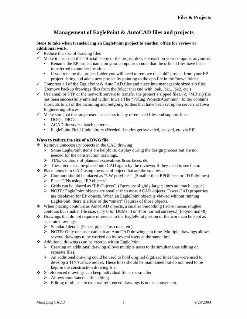
Management of EaglePoint & AutoCAD files and projects Steps to take when transferring an EaglePoint project to another office for review or additional work.
Reduce the size of drawing files Make it clear that the “official” copy of the project does not exist on your computer anymore:
Rename the EP project name on your computer to note that the official files have been transferred to another location.
If you rename the project folder you will need to remove the “old” project from your EP project listing and add a new project by pointing to the epp file in the “new” folder.
Compress all of the EaglePoint & AutoCAD files and place into manageable sized zip files. (Remove backup drawings files from the folder that end with .bak, .bk1, .bk2, etc.)
Use email or FTP or the network servers to transfer the project’s zipped files. (A 7MB zip file has been successfully emailed within Iowa.) The “P:\Eng Projects\Common” folder contains shortcuts to all of the incoming and outgoing folders that have been set up on servers at Iowa Engineering offices.
Make sure that the target user has access to any referenced files and support files. DOQs, DRGs ACAD linestyles, hatch patterns EaglePoint Field Code library (Needed if nodes get swiveled, resized, etc via EP)
Ways to reduce the size of a DWG file
Remove unnecessary objects in the CAD drawing Some EaglePoint items are helpful to display during the design process but are not
needed for the construction drawings. TINs, Contours of planned excavations & surfaces, etc These items can be placed into CAD again by the reviewer if they need to see them.
Place items into CAD using the type of object that are the smallest. Contours should be placed as “LW polylines”. (Smaller than EPObjects or 2D Polylines) Place TINs using “EP objects”. Grids can be placed as “EP Objects”. (Faces are slightly larger; lines are much larger.) NOTE: EaglePoint objects are smaller than most ACAD objects. Fewer CAD properties
are displayed for EP objects. When an EaglePoint object is viewed without running EaglePoint, there is a loss of the “smart” features of those objects.
When placing contours as AutoCAD objects, a smaller Smoothing Factor means rougher contours but smaller file size. (Try 0 for DEMs, 3 or 4 for normal surveys.) (Polynomial=0)
Drawings that do not require reference to the EaglePoint portion of the work can be kept as separate drawings.
Standard details (Fence, pipe, Trash rack, etc) NOTE: Only one user can edit an AutoCAD drawing at a time. Multiple drawings allows
several drawings to be worked on by several users at the same time. Additional drawings can be created within EaglePoint.
Creating an additional drawing allows multiple users to do simultaneous editing on separate files.
An additional drawing could be used to hold original digitized lines that were used to develop a TIN/surface model. These lines should be maintained but do not need to be kept in the construction drawing file.
X-referenced drawings can keep individual file sizes smaller. Allows simultaneous file editing Editing of objects in external referenced drawings is not as convenient.
Managing CADD 1 9/29/2003

Transferring Files
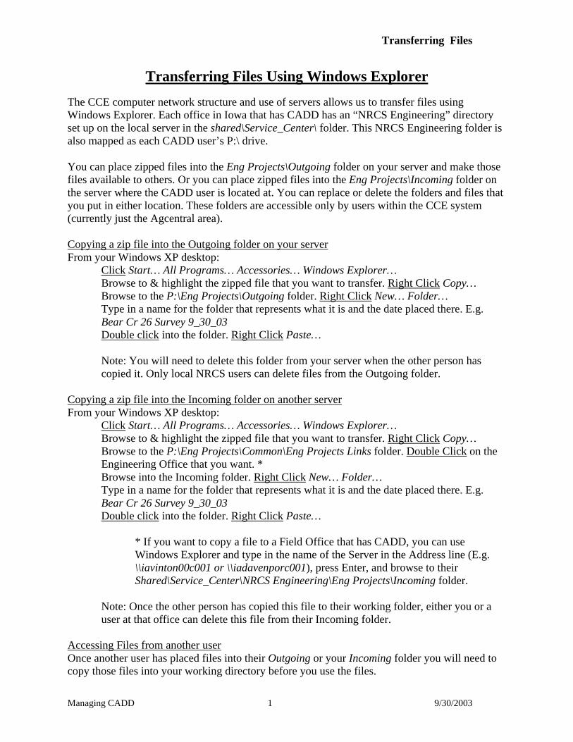
Transferring Files Using Windows Explorer
The CCE computer network structure and use of servers allows us to transfer files using Windows Explorer. Each office in Iowa that has CADD has an “NRCS Engineering” directory set up on the local server in the shared\Service_Center\ folder. This NRCS Engineering folder is also mapped as each CADD user’s P:\ drive. You can place zipped files into the Eng Projects\Outgoing folder on your server and make those files available to others. Or you can place zipped files into the Eng Projects\Incoming folder on the server where the CADD user is located at. You can replace or delete the folders and files that you put in either location. These folders are accessible only by users within the CCE system (currently just the Agcentral area). Copying a zip file into the Outgoing folder on your server From your Windows XP desktop:
Click Start… All Programs… Accessories… Windows Explorer… Browse to & highlight the zipped file that you want to transfer. Right Click Copy… Browse to the P:\Eng Projects\Outgoing folder. Right Click New… Folder… Type in a name for the folder that represents what it is and the date placed there. E.g. Bear Cr 26 Survey 9_30_03 Double click into the folder. Right Click Paste… Note: You will need to delete this folder from your server when the other person has copied it. Only local NRCS users can delete files from the Outgoing folder.
Copying a zip file into the Incoming folder on another server From your Windows XP desktop:
Click Start… All Programs… Accessories… Windows Explorer… Browse to & highlight the zipped file that you want to transfer. Right Click Copy… Browse to the P:\Eng Projects\Common\Eng Projects Links folder. Double Click on the Engineering Office that you want. * Browse into the Incoming folder. Right Click New… Folder… Type in a name for the folder that represents what it is and the date placed there. E.g. Bear Cr 26 Survey 9_30_03 Double click into the folder. Right Click Paste…
* If you want to copy a file to a Field Office that has CADD, you can use Windows Explorer and type in the name of the Server in the Address line (E.g. \\iavinton00c001 or \\iadavenporc001), press Enter, and browse to their Shared\Service_Center\NRCS Engineering\Eng Projects\Incoming folder.
Note: Once the other person has copied this file to their working folder, either you or a user at that office can delete this file from their Incoming folder.
Accessing Files from another user Once another user has placed files into their Outgoing or your Incoming folder you will need to copy those files into your working directory before you use the files.
Managing CADD 1 9/30/2003


License Manager
Eagle Point and AutoCAD License Manager Troubleshooting
All licenses are in use This is the message if all of the Eagle Point licenses are being used:
The following error message that contains “-4” means that all of the AutoCAD licenses on the license manager are being used:
Solution: Try using the software later after other users are done using the software.
Not correctly connecting to the license manager This error indicates that your computer was not able to contact the Eagle Point license manager:
Managing CADD 1 9/24/2003

License Manager
If you get the following error when launching AutoCAD, press the Cancel button:
An error message that appears after that with an error code of “-14” indicates that your computer was not able to contact the license manager.
Solution: Follow these “Troubleshooting” instructions: 1. Check the system variable settings for the non-working program
Start… Control Panel… System… Advanced…Environment Variables… for AutoCAD check ADSKFLEX_LICENSE_FILE, Value = @ST############.ag####.one.usda.gov (obtain correct value for your state) for Eagle Point check EPSERVTCP, Value = @ST############.ag####.one.usda.gov (obtain correct value for your state) 1.1. Values are missing or not correct: Log in as Local Administrator. Input the
correct variable & value. Retry software. 1.2. Values are correct but only one runs correctly. Reboot computer and retry. If still
not working, call “CADD support”. 1.3. Values are correct but neither program will run.
Reboot computer and retry. If still not working, go to #2
2. Check the Wide Area Network (WAN) connection to the license manager: Start… All Programs… Accessories… Windows Explorer… At the Address line input \\ ST############.ag####.one.usda.gov Press Enter, Observe the Explorer window
Managing CADD 2 9/24/2003
License Manager
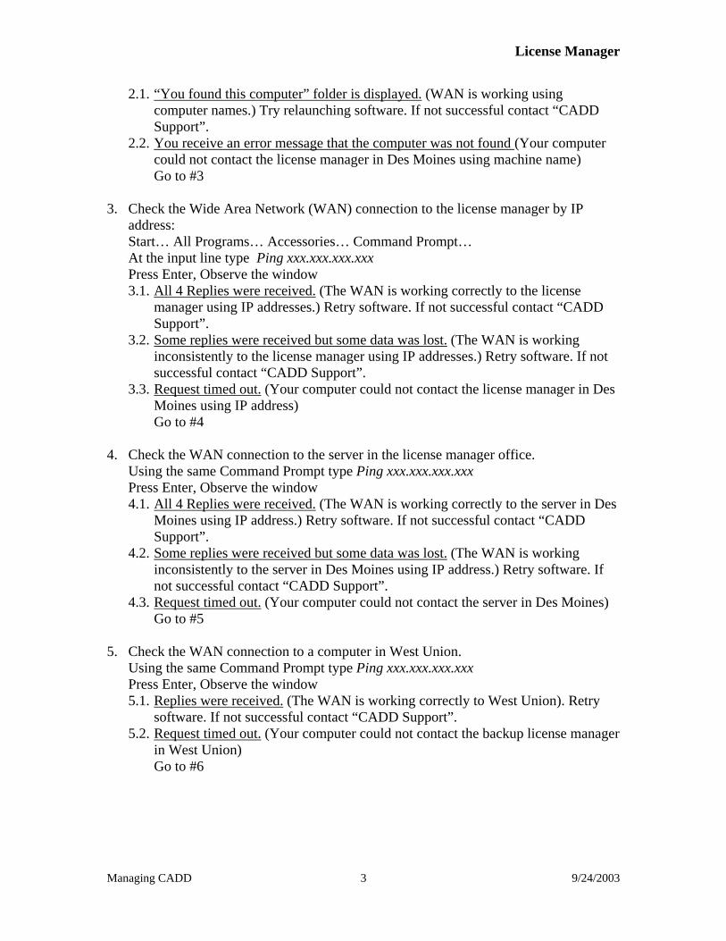
2.1. “You found this computer” folder is displayed. (WAN is working using computer names.) Try relaunching software. If not successful contact “CADD Support”.
2.2. You receive an error message that the computer was not found (Your computer could not contact the license manager in Des Moines using machine name) Go to #3
3. Check the Wide Area Network (WAN) connection to the license manager by IP
address: Start… All Programs… Accessories… Command Prompt… At the input line type Ping xxx.xxx.xxx.xxx Press Enter, Observe the window 3.1. All 4 Replies were received. (The WAN is working correctly to the license
manager using IP addresses.) Retry software. If not successful contact “CADD Support”.
3.2. Some replies were received but some data was lost. (The WAN is working inconsistently to the license manager using IP addresses.) Retry software. If not successful contact “CADD Support”.
3.3. Request timed out. (Your computer could not contact the license manager in Des Moines using IP address) Go to #4
4. Check the WAN connection to the server in the license manager office.
Using the same Command Prompt type Ping xxx.xxx.xxx.xxx Press Enter, Observe the window 4.1. All 4 Replies were received. (The WAN is working correctly to the server in Des
Moines using IP address.) Retry software. If not successful contact “CADD Support”.
4.2. Some replies were received but some data was lost. (The WAN is working inconsistently to the server in Des Moines using IP address.) Retry software. If not successful contact “CADD Support”.
4.3. Request timed out. (Your computer could not contact the server in Des Moines) Go to #5
5. Check the WAN connection to a computer in West Union.
Using the same Command Prompt type Ping xxx.xxx.xxx.xxx Press Enter, Observe the window 5.1. Replies were received. (The WAN is working correctly to West Union). Retry
software. If not successful contact “CADD Support”. 5.2. Request timed out. (Your computer could not contact the backup license manager
in West Union) Go to #6
Managing CADD 3 9/24/2003
License Manager
6. Check the local area network (LAN) connection to a computer in your office. Determine the IP address of a computer in your office that is running. Using the same Command Prompt type that IP address: e.g. Ping xxx.xxx.___.___ Press Enter, Observe the window 6.1. Replies were received. (The LAN is working correctly). Contact “CADD
Support”. 6.2. Request timed out. (Your computer could not contact a computer on your LAN)
Make sure LAN cables are connected correctly. Work with your local administrator to correct the LAN problem.
*CADD Support 1. Norman Friedrich 2. Ron Carper 3. Curt Fopma
Managing CADD 4 9/24/2003