Maintenance Facilities Report - UMSL
36
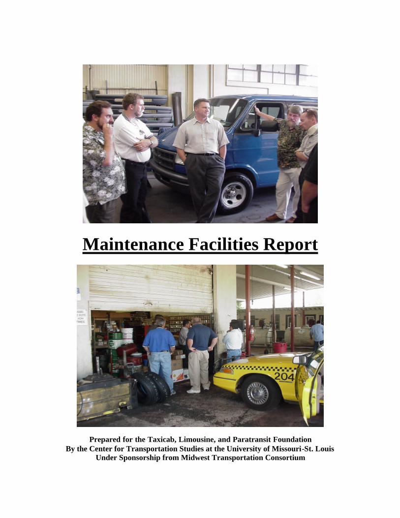
Maintenance Facilities Report Prepared for the Taxicab, Limousine, and Paratransit Foundation By the Center for Transportation Studies at the University of Missouri-St. Louis Under Sponsorship from Midwest Transportation Consortium
Transcript of Maintenance Facilities Report - UMSL
Maintenance Facilities Report
Prepared for the Taxicab, Limousine, and Paratransit Foundation By the Center for Transportation Studies at the University of Missouri-St. Louis
Under Sponsorship from Midwest Transportation Consortium
2
EXECUTIVE SUMMARY .............................................................................................. 3
INTRODUCTION............................................................................................................. 4
SPACE REQUIREMENTS.............................................................................................. 5
I. Administrative space ............................................................................................... 6
II. Transportation services/Operations services ...................................................... 7
III. Maintenance service ............................................................................................. 8
A. Running Repairs and Inspection Bays ........................................................... 8
Relationship with other areas ........................................................................ 9
Key design features....................................................................................... 10
B. Parts Room...................................................................................................... 12
Relationship with other areas ...................................................................... 12
Key design features....................................................................................... 12
C. Shop Area........................................................................................................ 13
IV. Vehicle parking ................................................................................................... 13
Key design features that need to be taken into consideration ........................ 15
Design Prototype for a Maintenance Facility, Fleet Size: 200-250 ............................. 18
Design Prototype for a Maintenance Facility, Fleet Size: 50-100 ............................... 19
APPENDIX I ................................................................................................................... 20
APPENDIX II .................................................................................................................. 23
Lift design options ..................................................................................................... 23
Selection factors ......................................................................................................... 25
Ten safety tips ............................................................................................................ 26
APPENDIX III ................................................................................................................ 28
APPENDIX IV................................................................................................................. 32
BIBLIOGRAPHY........................................................................................................... 35
SOURCES FOR APPENDICES.................................................................................... 36
3
EXECUTIVE SUMMARY
Purpose of the report
The objective of this research is to provide a design prototype for small and
medium fleet motor vehicle maintenance facilities. This synthesis is intended for use by
taxi, limousine and paratransit facility design consultants and engineers in determining
the basic requirements for the design of fleet maintenance facilities.
Further, this report will summarize the research findings, with regard to the space
needs of the maintenance facility, the functional relationships between the spaces, and
will take note of the key design consideration factors that are important for the planning
of the facilities.
Abiding by government regulations, including the National Building Code, ADA
regulations, the Clean Air Act Amendments (CAAA), the Clean Water Act (CWA),
Environmental Protection Act (EPA) regulations for above and underground storage
tanks and Occupational Safety and Health Administration (OSHA) regulations, is critical
to the design of transit fleet maintenance facilities. A list of the key design features that
need to be considered based on these regulations have been included in Appendix I.

4
INTRODUCTION
Just a little more than a hundred years ago, America’s public transit was animal
powered, with horses and mules pulling streetcars over miles of track. These cars and
horses were serviced and housed in barns (fleet maintenance facilities of former times).
As technology progressed, combustion engines and electricity replaced animal power in
transit maintenance facilities.1 Old streetcar barns have been replaced by sleek, efficient,
and environmentally friendly maintenance facilities—highly functional buildings with
comfortable working environments. They carefully take into account the functions they
perform on day-to-day basis, including preventive maintenance and inspection, daily
servicing of vehicles and major repairs. Today, there are maintenance facilities that cater
to buses, motor vehicles, trucks, etc; facilities designed to consider every maintenance
activity from dispensing transmission fluid to rebuilding an engine.
The transit fleet maintenance community is positioned to make some significant
advances in the new millennium.2 Changes in technology offer much potential for
supporting both traditional management activities and several equipment capabilities that
have recently become available, like paperless work order systems, computer networks to
track location and fuel consumption, and power-saving motion sensors.1 However, the
full benefits will be realized only after successfully navigating some significant
challenges. Ironically, the tendency is to view the technology itself as a key challenge,
but how fleet maintenance managers align their organizations in adapting to technology
probably will determine the extent of any advances. One key conclusion of a recent
1 “The New Transit Maintenance Facilities”; MDG in motion, Official Publication of Maintenance Design Group, MDG, http://www.maintdesign.com 2 ED Abrams, Henry Hide, Louisa Ho, Claire McKnight, Jim O’ Sullivan, Jim Price, John Schiavone, Stephen Stark, Frank Venezia; Transit Fleet Maintenance. TRB, National Research Council
5
study was that the success of a maintenance organization would depend on its ability to
adapt to change.3
With the increasing complexity of vehicle design and electronic technology many
challenges are ahead. Keeping abreast of such changes requires continual training, the
provision of effective diagnostic tools, and the implementation of uniform fleet
maintenance programs to ensure the achievement of optimum efficiencies. The fleet
management software packages available today address this issue and provide effective
fleet management solutions.
This report will attempt to draft prototype designs considering the minimal space
and functional requirements for small and medium fleet maintenance facilities. (Fleet
size 50 –250 motor vehicles). It will also discuss the desired functional relationships
between these spaces to maximize efficiency in operating these facilities.
SPACE REQUIREMENTS
The design of a maintenance facility begins with a brief analysis of the space
requirements of the site. Usually, the maintenance facility occupies ¼ of the site, with ½
the site allotted for parking and vehicle storage and ¼ for employee parking. 4 The site
may be selected based on (a) ease of access and proximity to service area, (b) availability
of utilities; for example, water, sanitary sewer, storm sewer, electric power, natural gas
etc., (c) topography (preferable that the terrain be level) and the surrounding
neighborhood with respect to environmental concerns and adjacent land use
3 Finegold, D., M. Robbins, and L. Galway. TCRP Report 29: Closing the Knowledge Gap for Transit Maintenance Employees: A Systems Approach. TRB, National Research Council, Washington, D.C., 1998, 62 pp. 4 Spielberg, F. and S.J. Andrle, “Transit Garage Planning and Guidelines, a Review,” SG Associates, Inc. and Clark, Nexsen, Owen, Barbie & Gibson, for Office of Planning, Urban Mass Transportation Administration (August 1987).
6
compatibility. After site selection, the space requirements of the facility are determined.
The space requirements for a fleet maintenance facility can be broadly categorized as:
I. Administrative space
II. Transportation services
III. Maintenance services
IV. Fleet storage
There requirements can be provided as separate spaces under the same roof in
which case it is called the single roof facility, or may be provided in different buildings,
which is not a cost-effective solution for small maintenance facilities. For the purpose of
analyzing the functional relationship between these areas, it is first important to
understand the function of these areas.
I. Administrative space
The administrative service area may include a number of functions such as
administration, accounting and data processing, marketing and planning, public
information, personnel and others. Conference areas and boardrooms are optional. The
size and the function of the maintenance facility determine which functions are included
in the administrative component. For example, if the maintenance facility manages
solely the fleet for a particular company, then the need for marketing and planning
departments is ruled out. Also, in the case of small maintenance facilities, conference
and boardrooms may not serve the purpose. The size of the administrative service area
depends on the number of administrative personnel on-site. The recommended space is
approx. 260 ft sq. per administrative employee.4 Central core administrative area is often

7
preferred. A central core administrative area reduces travel time from work-bays and
provides better supervision.
II. Transportation services/Operations services
The Transportation Service Area usually includes the common areas for drivers,
such as a waiting room, lockers and restrooms, the dispatch area, the trainers and the
supervisor’s office.4 The following diagram reiterates the necessary link between the
transportation and administration. Visual and pedestrian access is also illustrated
between the driver’s area and the Parking. 5 The dispatch area also requires adjacency
and visual contact with the driver’s waiting room.
Relationship with other areas
The transportation services office is located close to the administrative office, so
that the drivers do not have to pass through the maintenance shops when traveling
5 Regional Transportation Commission of Clark County (RTC)…Maintenance facility Design
PARKING
1
2
3
4
DRIVERS 1. TRANSPORTATION 2. DRIVERS WAITING
AREA 3. DISPATCH 4. ADMINISTRATION
8
between the transportation services and the car pickup area or the fleet storage area. It is
typically located close to the vehicle drop off and pickup area so that the drivers save
time and energy walking to and from their vehicles.
III. Maintenance service
This is where the vehicles are serviced and repairs are made. In addition it houses
the support functions associated with repairs. The functional spaces included in this area
are the repair bays or maintenance shops, the machine shop, the parts storage, the
maintenance offices, the wash bays, the preventive maintenance bays, and the mechanics
welfare room.
A. Running Repairs and Inspection Bays
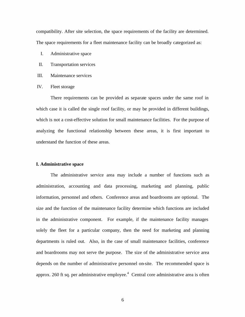
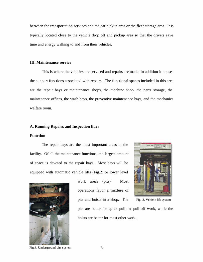
Function
The repair bays are the most important areas in the
facility. Of all the maintenance functions, the largest amount
of space is devoted to the repair bays. Most bays will be
equipped with automatic vehicle lifts (Fig.2) or lower level
work areas (pits). Most
operations favor a mixture of
pits and hoists in a shop. The
pits are better for quick pull-on, pull-off work, while the
hoists are better for most other work.
Fig. 2. Vehicle lift system
Fig.3. Underground pits system

9
Portable wheel lifts appear to provide more flexibility. These lifts only require a
solid level floor and electrical power to convert a normal work area into a lift/pit type
work area. This provides considerably more flexibility in arranging work-bays. The lifts
do have some restrictions. They take more time in raising vehicles, take up more floor
space and limit access to the underside of the vehicles. See APPENDIX II for more
information.
Typically, eighty percent of the repair bays in the facility are non-special bays.
The special bays include bays for steam cleaning or degreasing, paint booths with space
for paint preparation, body shop repair bays, the dynamometer repair bay, repair bays for
fare-boxes and radios, and bays for welding. Many of these special bays should be
enclosed for safety. In large maintenance facilities, these functions are provided in
separate bays, but in small maintenance facilities, these functions may be provided for in
a single enclosed bay, or sometimes may not be provided.6
Relationship with other areas
Repair bays are provided close to the inspection and preventive maintenance bays.
Also important is access to the parts room and the parking and fleet storage. Repair bays
are designed and located such that maintenance personnel can easily access them, with
parts cleaning area (shared) and a workbench w/vise (per bay) provided adjacent to the
bays.
6 Abrams, Edward M.; Spielberg, Frank, ‘ Regulatory Impacts on Design and Retrofit of Bus Maintenance Facilities, Transportation Research Board, National Academy Press, 1994.
10
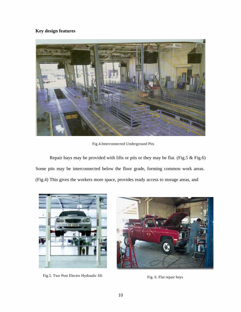
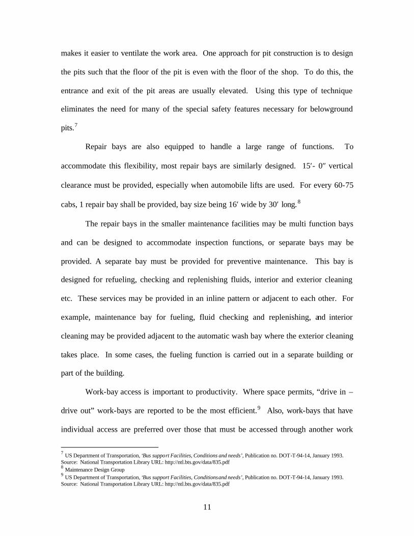
Key design features
Fig.4.Interconnected Underground Pits Repair bays may be provided with lifts or pits or they may be flat. (Fig.5 & Fig.6)
Some pits may be interconnected below the floor grade, forming common work areas.
(Fig.4) This gives the workers more space, provides ready access to storage areas, and
Fig. 6. Flat repair bays
Fig.5. Two Post Electro Hydraulic lift
11
makes it easier to ventilate the work area. One approach for pit construction is to design
the pits such that the floor of the pit is even with the floor of the shop. To do this, the
entrance and exit of the pit areas are usually elevated. Using this type of technique
eliminates the need for many of the special safety features necessary for belowground
pits.7
Repair bays are also equipped to handle a large range of functions. To
accommodate this flexibility, most repair bays are similarly designed. 15′- 0″ vertical
clearance must be provided, especially when automobile lifts are used. For every 60-75
cabs, 1 repair bay shall be provided, bay size being 16′ wide by 30′ long.8
The repair bays in the smaller maintenance facilities may be multi function bays
and can be designed to accommodate inspection functions, or separate bays may be
provided. A separate bay must be provided for preventive maintenance. This bay is
designed for refueling, checking and replenishing fluids, interior and exterior cleaning
etc. These services may be provided in an inline pattern or adjacent to each other. For
example, maintenance bay for fueling, fluid checking and replenishing, and interior
cleaning may be provided adjacent to the automatic wash bay where the exterior cleaning
takes place. In some cases, the fueling function is carried out in a separate building or
part of the building.
Work-bay access is important to productivity. Where space permits, “drive in –
drive out” work-bays are reported to be the most efficient.9 Also, work-bays that have
individual access are preferred over those that must be accessed through another work
7 US Department of Transportation, ‘Bus support Facilities, Conditions and needs’, Publication no. DOT-T-94-14, January 1993. Source: National Transportation Library URL: http://ntl.bts.gov/data/835.pdf 8 Maintenance Design Group 9 US Department of Transportation, ‘Bus support Facilities, Conditions and needs’, Publication no. DOT-T-94-14, January 1993. Source: National Transportation Library URL: http://ntl.bts.gov/data/835.pdf

12
area. This second aspect is even more important where vehicles frequently enter or exit
the work-bays as in the case of running repair bays.
B. Parts Room
Function
The parts room is a secure area for receiving, storage and issue of parts, and
materials. It provides storage inventory, supply and exchange of small parts and
maintenance supplies. It typically contains bins, shelving units and cabinets. Tires, body
parts and spare major components, such as engines and transmissions, are generally
stored in another area.
Relationship with other areas
It is located near the maintenance-repair area for ready access by mechanics and
on an outside wall to provide access to deliveries. The parts storage room is provided
adjacent to or included in the repair bays area.
Key design features
Vertical clearance of 10’ is required (8’ for mezzanine level). Wire mesh
enclosures may be provided to store secure items and warranted items. If the parts
storage room is provided at the mezzanine level, a parts lift may be provided for
transportation of heavy parts. Walls and floor are required to be soil and grease resistant,
for easy maintenance.
13
Security of parts is an important aspect that needs to be considered. Wire mesh
secure enclosures may be provided within the parts room for secure items storage,
warranty storage, etc.
C. Shop area
The shop area is a large space accommodating repair shops for the battery brake,
component rebuilds, electrical, tires, and welding and overhaul. These are support areas
to the repair and inspection bays. Usually, they provide for shop equipment like
workbench w/vise, parts cleaning tank, buffer/grinder with dust collector, hydraulic press,
drill press etc. The shop area is usually adjacent to the repair bays and the parts room.
IV. Vehicle Parking
Vehicle parking area occupies ½ of the site. Most of the fleet maintenance
facilities provide outdoor parking, though in some cases, parking is provided indoors,
where outdoor temperatures drop below freezing more than 100 nights per year. There
are advantages and disadvantages to both outdoor and indoor bus parking.
Outdoor bus parking creates problems because the vehicles are cold in the winter
and hot in the summer, thus increasing the engine run-time required to stabilize the
interior temperatures. The problems and cost of these conditions can be greatly reduced
with indoor parking. However, indoor parking is a significant capital investment. In
some climates, covered but not enclosed parking represents a compromise.
Another aspect that needs to be paid attention to in the design of indoors parking
areas is the ceiling height. Low ceilings in parking areas create exhaust emission
14
problems. It is common to reduce the height of the ceiling in bus parking garages to as
low a level as possible. This reduces construction cost and heating cost. However, low
ceilings make it extremely difficult to move air in sufficient volume to create an
acceptable environment during pullouts. Usually it has been suggested that the problems
with engine exhaust emissions were directly proportional to the lower ceiling height of
the parking garages.10 A minimum of 9′0″ height clearance should be provided.
10 US Department of Transportation, ‘Bus support Facilities, Conditions and needs’ , Publication no. DOT-T-94-14, January 1993. Source: National Transportation Library URL: http://ntl.bts.gov/data/835.pdf

15
Key design features that need to be taken into consideration § Ventilation problems in single roof facilities
Single roof facilities have operations, maintenance, vehicle parking, etc. all
assigned to separate areas but all in one enclosed building. A common problem found in
these designs is that the engine exhaust from the parking area seeps into the general
office area. Increasing exhaust capacity and installing a positive exhaust system may be
some methods of avoiding this problem.
§ Facility life span and changing requirements impact design
Because of the extended life and rapidly changing requirements of facilities,
flexibility and adaptability are very important design characteristics. Also, ongoing
modifications and rehabilitations are needed to keep facilities functional. Based on the
extended age of many facilities, fleet maintenance facilities should be designed for
extended lives.11 This design consideration includes designing the facility systems (i.e.,
electrical systems, ventilation, parking, work-bays, etc.) to exceed minimum or current
requirements. Also, with changing regulations (ADA, yard run-off, alternative fuels,
etc.), changing service demands, and changing vehicle types, it is difficult to make
capacity or equipment projections for a facility that is intended to last for many years.
The facilities should also be designed with maximum flexibility to meet changing needs.
11 US Department of Transportation, ‘Bus support Facilities, Conditions and needs’ , Publication no. DOT-T-94-14, January 1993. Source: National Transportation Library URL: http://ntl.bts.gov/data/835.pdf
16
§ Concrete parking lots are more cost effective.
Concrete lots cost more initially, but are reported to last much longer. As a result,
many systems recommend the use of concrete parking lots because of the improved life-
cycle cost. Aspects of transit operations that tended to quickly degrade asphalt lots are as
follows12:
§ Petroleum product spills, such as those that occur with normal transit operations
(e.g., leaking engines), help dissolve the asphalt,
§ Large amounts of water runoff result after vehicle washing. The water is
especially damaging to asphalt yards during freezing temperatures.
§ Warm weather and the weight of heavy-duty vehicles quickly degrade the
surface. (This aspect needs to be paid attention to if the facility extends its
services to include heavy-duty vehicle maintenance.)
§ Many aspects of facilities should be designed to exceed minimum building codes.
Most architectural aspects of transit buildings (i.e., ventilation, battery room
exhaust, electrical capacity, etc.) are designed close to the minimum code requirements.
However, in heavy-duty applications, such as a transit garage, these are often found to be
inadequate. Over time, capacity often has to be increased at considerably more expense.
This has been found to be particularly true of electrical capacity. Over time, tooling and
fixtures are added which require additional electrical power. The cost of providing the
necessary capacity initially is much less than having to increase capacity at a later date.
12 US Department of Transportation, ‘Bus support Facilities, Conditions and needs’, Publication no. DOT-T-94-14, January 1993. Source: National Transportation Library URL: http://ntl.bts.gov/data/835.pdf
17
§ Increased consideration should be given to future needs as part of site selection
process.
§ More energy conservation measures needed.
There are several private companies that offer to analyze and equip transit
facilities with more energy efficient equipment/processes. These companies charge
nothing and only share in the utility savings. Typical examples of approaches used in
such conservation efforts are light timers and zoned heat/air conditioning. It is obvious
from these examples that more operating efficiencies could be gained in most transit
facilities through the efficient use of energy
§ The facility should be designed to meet American with Disabilities Act (ADA)
Regulations, Clean Air Act Amendments of 1990, Clean Water Act and Clean Air
Act Amendments of 1990. (APPENDIX I)
§ The underground fuel storage tanks shall be designed and handled to meet the
Environmental Protection Agency (EPA) Regulations on Underground Storage
tanks. (APPENDIX I)
18
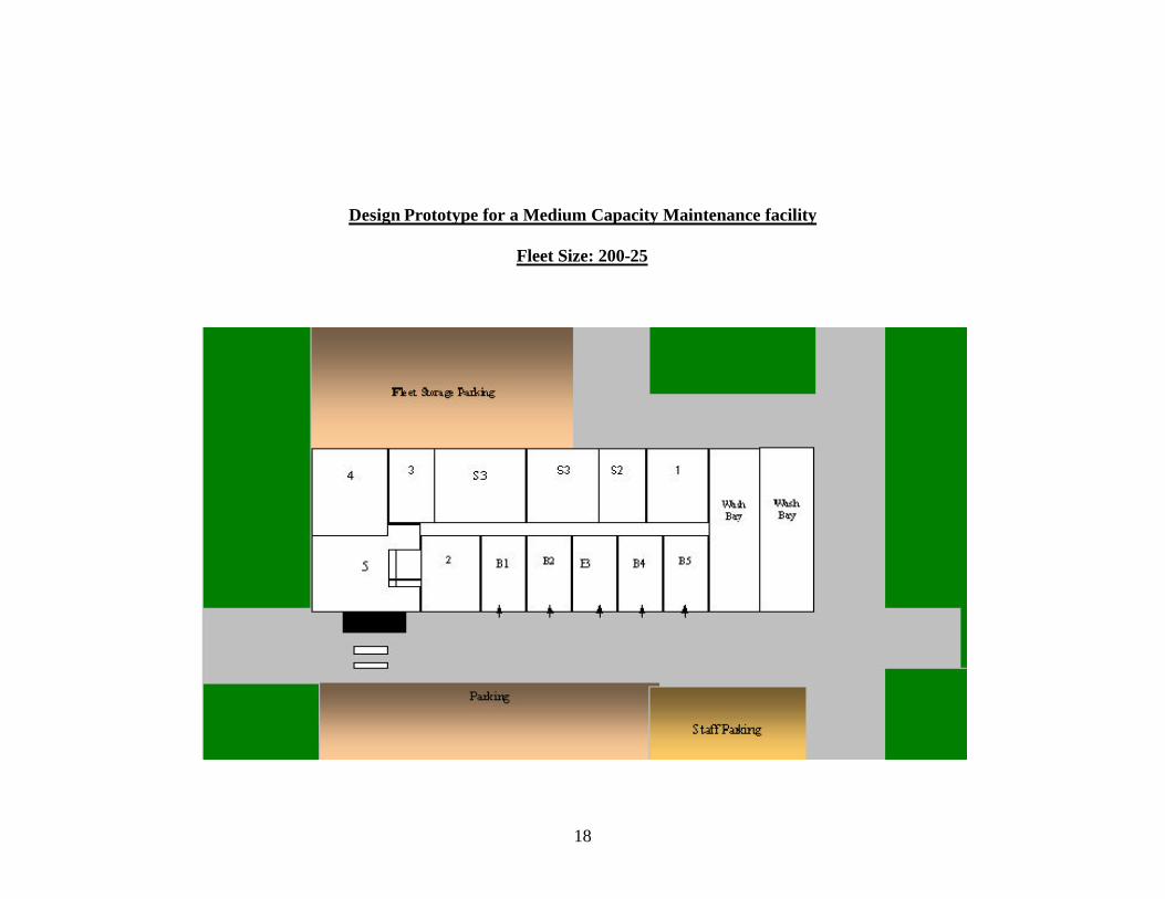
Design Prototype for a Medium Capacity Maintenance facility
Fleet Size: 200-25
19
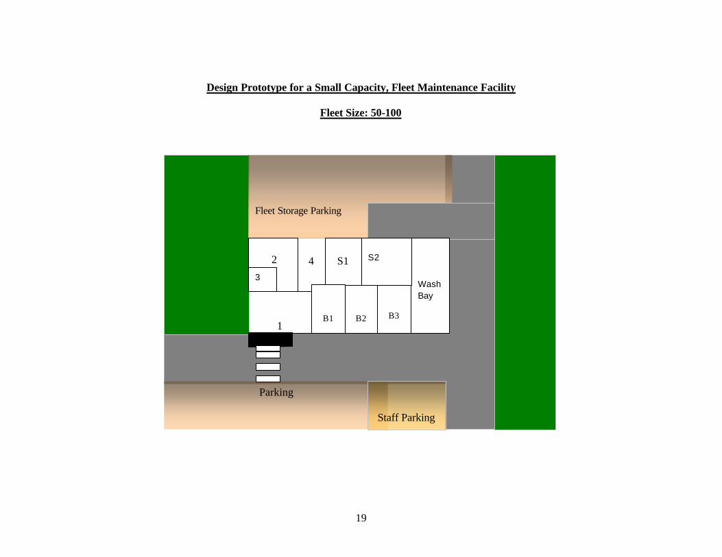
Design Prototype for a Small Capacity, Fleet Maintenance Facility
Fleet Size: 50-100
B2
B3
1
4
Parking
Fleet Storage Parking
Staff Parking
Wash Bay
S2
S1
B1
2 3
20
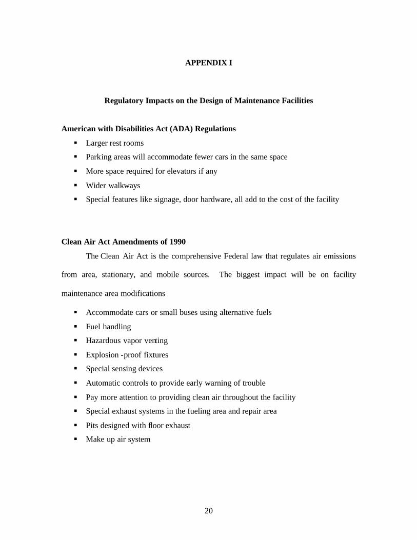
APPENDIX I
Regulatory Impacts on the Design of Maintenance Facilities
American with Disabilities Act (ADA) Regulations
§ Larger rest rooms
§ Parking areas will accommodate fewer cars in the same space
§ More space required for elevators if any
§ Wider walkways
§ Special features like signage, door hardware, all add to the cost of the facility
Clean Air Act Amendments of 1990
The Clean Air Act is the comprehensive Federal law that regulates air emissions
from area, stationary, and mobile sources. The biggest impact will be on facility
maintenance area modifications
§ Accommodate cars or small buses using alternative fuels
§ Fuel handling
§ Hazardous vapor venting
§ Explosion -proof fixtures
§ Special sensing devices
§ Automatic controls to provide early warning of trouble
§ Pay more attention to providing clean air throughout the facility
§ Special exhaust systems in the fueling area and repair area
§ Pits designed with floor exhaust
§ Make up air system
21
Clean Water Act
The Clean Water Act regulates the amount of chemicals/toxics released by the
facility via direct and wastewater discharges. These standards usually set concentration-
based limits on the discharge of a given chemical by the facility. If a facility is
discharging directly in to a stream or river, (usually not the case, due to their size,
maintenance facilities are likely to be discharging any wash waters to a sanitary sewer
system, not to a pipe which goes to a stream or river) it is required to obtain the National
Pollutant Discharge Elimination System (NPDES) permit. Other requirements include:
§ Recycle wash water
§ Provide facilities for processing the site drainage before draining into the
municipal sanitary sewer system.
§ Using oil/water separators for the drain water to flow into before being discharges
into the sewer system.
§ Floors where vehicles are repaired or fueled must be provided with drains so that
any spills are captured.
§ The storage and distribution of oils, fluids, and lubricants must also be carefully
considered. (In some maintenance facilities, all vehicle fluids are distributed to
repair bays from a central storage area by visible fluids are distributed to repair
bays from a central storage area by visible overhead piping and are dispensed
from pull-down hoses. This minimizes the spills as well as saves money due to
bulk purchasing of engine oils and fluids.)
Environmental Protection Agency (EPA) Regulations on Underground Storage
tanks (used to store fuels)
§ Double walled tanks with spill prevention features… underground piping to and
from the tank must also be double walled
§ Leak detectors and level monitors
§ Consider using above ground storage tanks for storing fuels (steel)
22
§ Material used for the construction or lining of these tanks must be compatible
with the substance to be stored
§ Other acceptable materials for constructing UST's- Fiberglass- reinforced plastic,
steel tanks clad with Fiberglass reinforced plastic
Occupational Safety and Health Administration (OSHA) Regulations Occupational
Safety and Health Administration (OSHA) Regulations
§ Eye protection: An eye wash area must be provided near the maintenance
workshops.
§ Pit protection: Chained-off area around pits should be provided when they are not
in use.
§ Clear air around electrical/mechanical equipment: Shields must be provided
around certain machinery such as grinders.
§ Safe working surfaces: Non-skid working surfaces must be provided, especially in
the repair bays, the shop area and the vehicle wash area.
§ Required and relevant signage should be provided around the facility.
§ Lift- locks should be provided for automatic lifts, also safety stands need to be
provided underneath the vehicle when it is raised on a lift.
§ Good sprinkler systems (fire extinguishers in the case of small facilities) and fire
lanes should be provided around and through the building.
23
APPENDIX II
Lift Design Options
Cost estimates based upon current market conditions for different types of lifting
systems are outlined below. These costs are greatly influenced by government regulation
and local soil conditions.
INSTALLATION COSTS
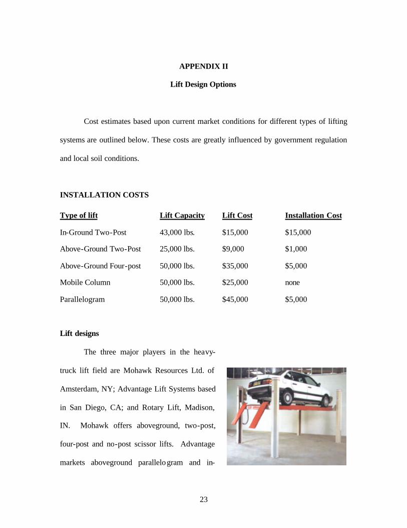
Type of lift Lift Capacity Lift Cost Installation Cost
In-Ground Two-Post 43,000 lbs. $15,000 $15,000
Above-Ground Two-Post 25,000 lbs. $9,000 $1,000
Above-Ground Four-post 50,000 lbs. $35,000 $5,000
Mobile Column 50,000 lbs. $25,000 none
Parallelogram 50,000 lbs. $45,000 $5,000
Lift designs
The three major players in the heavy-
truck lift field are Mohawk Resources Ltd. of
Amsterdam, NY; Advantage Lift Systems based
in San Diego, CA; and Rotary Lift, Madison,
IN. Mohawk offers aboveground, two-post,
four-post and no-post scissor lifts. Advantage
markets aboveground parallelogram and in-

24
ground non-hydraulic designs. Rotary has both aboveground and in-ground designs.
All types have disadvantages as well as advantages.
Four-Post Above-Ground Lifts
Advantages: These are easy to load and can be used for both PM's and service. Portable
designs generally have few side obstructions. Platform lifts can service all vehicles.
Adjustable runways can lift forklifts with narrow tire width. Rolling jacks provide
"wheel freeing" capability for tire and brake service.
Disadvantages: Somewhat wide. Corner posts can get in the way. Tire work is
sometimes hard to do. Crossbeams can inhibit front-end work.
Parallelogram Above-Ground Lifts
Advantages: These can accommodate most fleet vehicles. They can be portable and have
no outside posts to hinder tire work. Relatively small space requirement, they can be
flush mounted and have lights in the platform.
Disadvantages: The platform can get in a technician's way and some designs have a
continuous base that can be a trip hazard or inhibit some work. They need additional
space fore and aft due to movement of the superstructure when raising and lowering the
lift.
25
Mobile Column Above-Ground Lifts
Advantages: These offer multiple lift application. They're portable and generally good
for repairs that would tie up bays. The use of jack-stands allows one lifting unit to be
used in multiple bays, both indoor and outdoor.
Disadvantages: They're relatively slow to set up, have many moving parts and leave
electric cables on the floor. Tire work can be difficult.
In-Ground Lifts
Advantages: These require minimum floor space and offer a clear floor when the lift is
not in use. Wheels are free as soon as the vehicle is lifted. There are no posts or legs to
inhibit side access.
Disadvantages: Poor for steam cleaning and offer no lights. They are often slow to set up
and may not lift all vehicles. Pistons get in the way of work for some jobs.
Selection Factors
There is no single lift design that will fill all needs. Here are some factors to be
considered:
• Type of vehicles to be lifted and the amount of time it will be used
• Initial cost
• Is the facility, owned or leased? Does it require layout changes? What are the soil
and water conditions?
• Space available in the facility for the lift, including ceiling limitations, and the
amount of work area that will be fully or partially restricted. Vehicle turning
radius in and out of the building could be a factor.
• Maintenance and repair of lift

26
• Noise levels produced
• Warranty
• Service ava ilability
• Will work be performed outside?
All major lift suppliers have developed programs, including computer-aided designs, to
assist fleet managers in making the correct selection.
Tom Phillips, Vice-President of Marketing at Rotary Lift, suggests that the consideration
of the personal preferences of owners, managers and technicians be added to the list
above.
Non-Hydraulic In-Ground Lifts
This lift design is a solution to the problems of oil leakage associated with in-ground lifts.
The non- hydraulic in-ground lift's electromechanical design requires no hydraulic fluid,
thereby eliminating environmental risks caused by fluid leakage. The system is
suspended from the shop floor and does not require a foundation under its lifting
mechanism. Since the entire lift mechanism can be removed, repairs or relocation require
no jackhammer, concrete work or extensive downtime.
Ten Safety Tips
1. Operating controls are designed to close when released. Do not block or override
them.
2. Never overload a lift. The manufacturer's rated capacity is shown on the
nameplate affixed to lift.
3. Positioning of vehicle and operation of lift should be done only by trained
personnel.
4. Never raise a vehicle with anyone in it.

27
5. Keep the lift area free of obstructions, grease/oil and other debris.
6. Before driving a vehicle over a lift, position its arms and supports to provide an
unobstructed clearance.
7. Load the vehicle on a lift carefully. Position lifts supports to contact at
recommended lifting points. Raise the lift until supports contact the vehicle.
Check supports for secure contact. Raise the lift to desired working height.
CAUTION: If work will be done under the vehicle, the lift should be raised high
enough for its locking device to be engaged.
8. Note that with some vehicles, the removal or installation of components may
cause a critical shift in the center of gravity and result in instability. Refer to the
lift manufacturer's recommendation.
9. Before lowering a lift, be sure tool trays, stands etc. are removed from under the
vehicle. Release any locking devices before attempting to lower lift.
10. Before removing a vehicle from the lift area, position arms and supports to
provide unobstructed exit.
28
APPENDIX III
FLEET MAINTENANCE
Vehicle and Equipment Operation, Maintenance and Repair
Your facility can contribute contaminants to runoff when vehicles and equipment are
improperly operated, maintained or repaired. Leaky and poorly maintained equipment
and improper maintenance work areas might result in an illegal discharge.
General Pollution Prevention BMPs
§ Inspect all vehicles and heavy equipment frequently for leaks.
§ Conduct all vehicle and equipment maintenance at one location away from storm
drains, preferably on a paved surface under cover.
§ Move activities indoors, or cover equipment areas with a permanent roof.
Conduct maintenance only in areas designed to prevent storm water pollution.
§ Inspect and clean equipment to prevent leaks and excessive buildup of
contaminants. Keep drip pans and containers under areas that might drip.
§ Use drip pans or dropcloths to catch drips and spills if you drain and replace
motor oil, radiator coolant, or other fluids on site.
§ Never pour materials down storm drains. Connect process equipment areas to the
sanitary sewer or a facility wastewater treatment system.
§ Avoid hosing down work areas. Clean small spills with rags; conduct general
clean up with damp mops and clean larger spills with absorbent material.
§ Use non-toxic substitutes for chemicals when possible. Recycle greases, oil &
filters,
§ Antifreeze, cleaning solutions, batteries and hydraulic & transmission fluids.
§ Do not use diesel to lubricate equipment or parts.
§ Clean up spills immediately to minimize safety hazards and deter spreading
§ Train employees on discharge prohibitions.

29
Vehicle and Equipment Fueling
Spilled fuel can contribute contaminants to runoff from your facility. Improperly stored
rags used to clean up spilled fuel may also result in an illegal discharge.
General Pollution Prevention BMPs § Covering fueling areas.
§ Install perimeter drains or slope the surrounding pavement inward with drainage
to a sump or an oil-water separator.
§ Pave fueling areas with concrete rather than asphalt or apply a sealant to protect
asphalt from spilled fuels.
§ Install vapor recovery nozzles to control drips.
§ Discourage “topping off” fuel tanks.
§ Use a drip pan to collect drips and avoid spills.
§ Use absorbent materials or mop up small spills, and for general cleaning rather
than hosing down the area. Remove the absorbent materials promptly.
§ Use a rag cleaning service for contaminated rags used to clean up spills, which
cannot be disposed of in trash.
§ Transport industrial equipment to a designated fueling area rather than using
mobile fueling.
§ Clean up spills immediately to minimize safety hazards and deter spreading.
§ Train employees on proper fueling and cleanup procedures.
30
Vehicle and Equipment Washing and Cleaning
Your facility can contribute contaminants to runoff if wash water from equipment and
vehicle cleaning is rinsed onto parking lots or into gutters or storm drains. Improperly
stored rags may also result in an illegal discharge.
General Pollution Prevention BMPs
§ If possible use off-site commercial washing and steam cleaning.
§ Use designated wash areas, preferably covered, to prevent contact with storm
water. Berm wash areas or use other measures to contain wash water.
§ Designate a washing site for vehicles where water will drain by gravity to the
sewer system.
§ Never discharge wash water to the storm drain. Discharge it to the sanitary sewer
after contacting your local sewer agency to find out if pre-treatment is required, or
if possible, filter and recycle it.
§ Alternatively, divert wash water to an open lawn or other vegetated areas so that it
can percolate into the ground.
§ If it is not possible to divert wash water to the sanitary sewer or a vegetated area,
use at-grade storm drains fitted with filter fabric bags. These bags can be hung
down into the drains’ catch basins to filter out solids from the wash water runoff.
The solids can be removed when the bags are full.
§ Protect curb gutter inlets with filter fabric to trap solids from the wash water
runoff.
§ Post signs in the washing area that states that oil changes are prohibited there.
§ Wash vehicles with biodegradable, phosphate-free detergent.
§ Use non-toxic cleaning products – baking soda paste for battery heads, cable
clamps, and chrome; baking soda mixed with a mild, biodegradable dishwashing
soap for wheels and tires; white vinegar or lemon juice mixed with water for
windows.
§ Use a bucket (not a running hose) to wash and rinse cars to conserve water.

31
§ Use alternative washing and cleaning methods to reduce the potential for non-
storm water discharges. If possible, use “dry” cleaning methods, such as wiping
down, rather than hosing vehicles or equipment.
§ Avoid pressure washing if possible. Conduct pressure washing only if you are
equipped to capture and properly dispose of all wash water. This area should be
bermed to collect the wash water and graded to direct the wash water to a
treatment facility. In addition, use high-pressure, low-volume water to reduce
overspray.
§ Another way to recycle water is to use wash water from the final wash step for the
first wash step, which doesn’t require clean wash water. Likewise, use final rinse
water for the first rinse step, which doesn’t require clean rinse water.
§ Make sure that the drains at your facility are installed with grit traps and are
routed through an oil separator.
§ Properly contain and dispose of clean up materials (rags, towels, absorbent
materials, etc.).
§ Label all storm drain inlets “No Dumping”.
§ Educate employees on proper washing methods to prevent pollution.
32
APPENDIX IV
TIPS: Pollution Prevention Guide for
Fleet Maintenance Facilities
Antifreeze
• Recycle antifreeze either on-site or off-site. If more than 1,000 gallons per year of
antifreeze is used, then the payback period will generally be less than one year.
Parts Cleaning
• Reuse solvent by installing filtration or distillation units.
• Cover sinks to prevent solvent evaporation loss.
• To prevent spillage, remove parts from washers slowly.
• Consider alternatives to hazardous solvents. Many nonhazardous solvent
substitutes are available, including high flash point hydrocarbon solvents (greater
than 150 degrees F) and aqueous-based (water-based) solvents. (Note: Non
hazardous solvents can become hazardous as a result of contamination from, for
example, carburetor cleaner, gasoline, or hazardous solvents.)
• Consider installing a bioremediation parts washer that uses enzymes to eat oil and
grease.
Oil Conversion and Filtration
• Contract with an oil recycler for waste oil collection and recycling.
33
• Institute an oil analysis program to ensure that oil is only changed when
necessary. Reliable, low cost oil analysis equipment is available.
• Consider installing bypass filtration systems to extend oil life. Bypass filtration
systems generally remove impurities as small as 1 micron in size.
• Drain and crush used oil filters and send to a recycling company. Certain
companies recycle every component of the filter, including residual oil, metal, and
the filter component.
• Install reusable screen filters for the main oil filter.
Aerosol Products
(Pressurized aerosol cans are considered hazardous and cannot legally be thrown in the
trash. Cans may be depressurized by spraying remaining propellant or by special
equipment that allows the can to be punctured in a safe manner.)
• Purchase chemicals (such as spray lubricant) in bulk and apply with either pump
sprayers or new specialized spray cans which can be pressurized up to 200 pounds
per square inch with shop air.
• Empty and depressurize used aerosol cans. Send the empty cans for metal
recycling.
Facility Maintenance and Cleaning
• Minimize spills and clean up by using drip pans.
• Use reusable absorbents and recovering spilled fluids with wringers for recycling.
If wringing out flammable solvents, be sure to electrically ground the wringer.
• Sweep shop floors instead of hosing them down with water.
• Build a solids tray to reduce solids in the sump. Reassess the need for sumps. If
you don't need a sump, plug it.
34
• Send contaminated shop rags to an industrial laundering facility for cleaning and
reuse.
(Note: The facility must be in compliance with all federal and state wastewater
discharge regulations.)
Batteries
• Store lead-acid batteries, upright and off ground with a leak containment system
around the area.
• Extend lead-acid battery life with advanced battery management programs.
Trickle charge systems, solar trickle charge systems, and brass connectors can
significantly extend battery life by improving conductivity and reducing sulfation
of the lead plates in the battery.
• Consider new deep-cycle batteries, which can last much longer than conventional
batteries.
Source: P2 Tips for specific Businesses and Processes
35
Bibliography
1. ‘The New Transit Maintenance Facilities”; MDG in motion, Official Publication of
Maintenance Design Group, MDG, http://www.maintdesign.com
2. Ed Abrams, Henry Hide, Louisa Ho, Claire McKnight, Jim O’ Sullivan, Jim Price,
John Schiavone, Stephen Stark, Frank Venezia; “Transit Fleet Maintenance”. TRB,
National Research Council
3. Finegold, D., M. Robbins, and L. Galway. “TCRP Report 29: Closing the Knowledge
Gap for Transit Maintenance Employees: A Systems Approach”. TRB, National
Research Council, Washington, D.C., 1998, 62 pp.
4. Spielberg, F. and S.J. Andrle, “Transit Garage Planning and Guidelines, a Review,”
SG Associates, Inc. and Clark, Nexsen, Owen, Barbie & Gibson, for Office of Planning,
Urban Mass Transportation Administration (August 1987).
5. Regional Transportation Commission of Clark County (RTC)…“Maintenance facility
Design”.
6. Abrams, Edward M.; Spielberg, Frank, “Regulatory Impacts on Design and Retrofit of
Bus Maintenance Facilities”, Transportation Research Board, National Academy Press,
1994.
7. US Department of Transportation, ‘Bus support Facilities, Conditions and needs’,
Publication no. DOT-T-94-14, January 1993. Source: National Transportation Library
URL: http://ntl.bts.gov/data/835.pdf
8. Maintenance Design Group
36
9. US Department of Transportation, ‘Bus support Facilities, Conditions and needs’,
Publication no. DOT-T-94-14, January 1993..Source: National Transportation Library
URL: http://ntl.bts.gov/data/835.pdf
Sources for Appendices:
Appendix I
Regulatory Impacts on the Design of Maintenance Facilities, TRB Publications
Federal Transit Administration; http://www.fta.dot.gov/library/legal/dfregs.htm
§ American with Disabilities Act
§ Nondiscrimination on the Basis of Disability in Programs and Activities
Receiving or Benefiting From Federal Financial Assistance--
Subpart C—Enforcement 49 CFR PART 27;
http://www.fta.dot.gov/library/legal/dfregs.htm
§ Transportation Services for Individuals with Disabilities (ADA) 49 CFR 37
§ Accessibility Specifications for Transportation Vehicles 49 CFR 38
Environmental Protection Agency; http://www.epa.gov
Clean Air Act Amendments of 1990; http://www.epa.gov/airmarkt/arp/regs/caaa.html
Clean Water Act, 40 CFR 122; http://www.epa.gov/earth1r6/6en/w/40cfr122.pdf
Environmental Protection Agency (EPA) Regulations on Underground Storage tanks
(used to store fuels) 40 CFR 280; http://www.epa.gov/swerust1/fedlaws/cfr.htm
Appendix II
www.mohawklifts.com/whenlift.htm
Appendix III
http://www.dfwstormwater.com/pdfs/fleet_bmps.pdf
Appendix IV
www.twua.org/p2/Index2.html, Pollution Prevention for Wastewaters