Maintenance and Service Instruction - IMO · ACE3 0620.06 GB 3 Exploded view Fig. 1 All work...
12
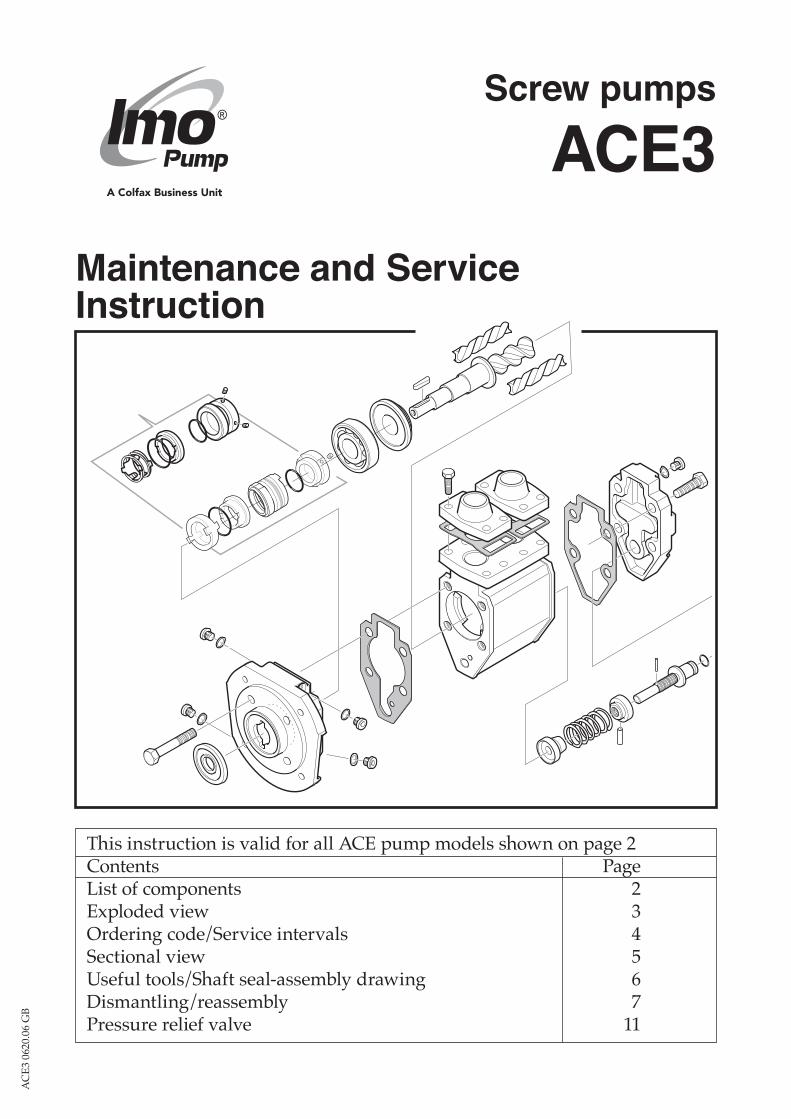
This instruction is valid for all ACE pump models shown on page 2 Contents Page List of components 2 Exploded view 3 Ordering code/Service intervals 4 Sectional view 5 Useful tools/Shaft seal-assembly drawing 6 Dismantling/reassembly 7 Pressure relief valve 11 Screw pumps ACE3 Maintenance and Service Instruction ACE3 0620.06 GB
-
Upload
nguyennhan -
Category
Documents
-
view
214 -
download
0
Transcript of Maintenance and Service Instruction - IMO · ACE3 0620.06 GB 3 Exploded view Fig. 1 All work...
This instruction is valid for all ACE pump models shown on page 2Contents PageList of components 2Exploded view 3Ordering code/Service intervals 4Sectional view 5Useful tools/Shaft seal-assembly drawing 6Dismantling/reassembly 7Pressure relief valve 11
Screw pumps
ACE3Maintenance and ServiceInstruction
AC
E3 0
620.
06 G
B

2 www.imo.se
AC
E3 0
620.
06 G
B
Before commencing any work, read this instruction carefully! Failure to comply with these instructions may cause damage and personal injury!!�
Valid for all pumps in sizes: ACE 025/032/038 Rotor diameter and Generation: D3/K3/L3/N3 With version codes: N V B P Also valid for pump options: A101 T The version code is composed of the letters in the 4 columns. Example of pump designations std: ACE 025L3 NTBP; option: ACE 038N3 NVBP A101
List of components
For more information about the pumps identification code, technical data and performance we refer to the ACE Product description. For more information about the pumps installation, Start-up and trouble shooting we refer to the IMO Installation and Start-up instruction for Low Pressure Pumps.
Explanations:G011: Rotor setG012: Rotor setG050: Shaft sealG053: Minor kitG054: Major kitG057: Joint kitG070: Valve element
Notes:1) Version NTBP2) Removed from
August 2011
Pos. no
Components included in spare parts sets:Denomination Q-ty G011 G012 G050 G053 G054 G057 G070 Notes
1010 Power rotor 1 x (x)1020 Power rotor 1 x x113 Key 1 x x x122 Ball bearing 1 x x x125 Secondary seal 1 x x x x 1201 Idler rotor 2 x (x)202 Idler rotor 2 x x351 Balancing bush 1 x x x401 Pump body 1416 Suction flange 1417 Screw 8418 Gasket to suction
flange1 x x x
423 Gasket to dis-charge flange
1 x x x
427 Discharge flange 1440 Return vaöve 1 2451 Screw 4453 Screw 4462 Plug 1462A Sealing washer 1 x x x463 Plug 1463A Sealing washer 1 x x x501 Front cover 1506 Gasket 1 x x x509 Shaft seal 1 x x x537 Deaeration plug 2537A Washer 2 x x x551 Rear cover 1556 Gasket 1 x x x557 Plug 1557A Washer 1 x x x605 O-ring 1 x x x x608 Valve spindle 1 x x608A Tension pin 1 x x6120 Set screw 1 x x613 Pin 1 x x614 Valve piston 1 x x615 Valve spring 1 x x
3
AC
E3 0
620.
06 G
B
www.imo.se
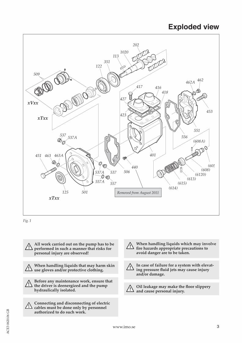
Exploded view
Fig. 1
All work carried out on the pump has to be performed in such a manner that risks for personal injury are observed!
When handling liquids that may harm skin use gloves and/or protective clothing.
!
!
!
!
When handling liquids which may involve fire hazards appropriate precautions to avoid danger are to be taken.
In case of failure for a system with elevat-ing pressure fluid jets may cause injury and/or damage.
Oil leakage may make the floor slippery and cause personal injury.
Connecting and disconnecting of electric cables must be done only by personnel authorized to do such work.
! Before any maintenance work, ensure that
the driver is deenergized and the pump hydrauli cally isolated.
!
451
501 125
463 463A
537A 537
557A 557
537A537
506440
401
556551
453
(608A)
(614)(615)
(613)(6120)
(608)(605)
462A 462
122351
1131020
202
509
418416417
423
427xVxx
xTxx
xTxxRemoved from August 2011

4 www.imo.se
AC
E3 0
620.
06 G
B
Recommendation:For maintenance the following spare part sets are recommended:
Set: To be used:G057 Joint kitFor dismantling the pump.
G053 Minor kitFor service.
G054 Major kitFor repair after damage or greater wear.
Ordering example:For IMO-pump ACE 032N3 NVBP, serial number 456789: Shaft seal pos G050 p/n 194030 Valve element pos G070 p/n 189873
Item Spare Parts sets 025 032 038G012 Rotor set CW-rotation (std)
Low lead-L3 190486 190485 –Low lead-K3 – – 190482Normal lead-N3 190487 190484 190483High lead-D3 – – 192698
G011 Rotor set CCW-rotationNormal lead-N3 190492 190491 190488
G050 Shaft seal-xVxx 194030 194030 194030Shaft seal-xTxx 190495 190495 190497
G053 Minor kit-xVxx 190501 190710 190500Minor kit-xTxx 190503 190712 190499
G054 Major kit=G012(G011)+G053+G070G057 Joint kit-xVxx 190525 190714 190522
Joint kit-xTxx 190524 190713 190523G070 Valve element 189873 189873 189873125 Secondary seal xTxx 190469 190469 190468
Part numbers for pump size
Ordering code
Inspection of shaft sealExcessively leaking shaft seals (more than 10 drops per hour) should be changed without delay, as the leakage normally will grow worse and cause addi-tional damage. In installations where unplanned shut downs must be avoided, it is advisable to dismantle the pump for a thorough inspection and thereby change out shaft seal and ball bearing, every three years as a max period.It is recommended always to have the spares includ-ed in minor spare part kit available.
Inspection of rotorsA quick inspection of the idler rotors can be made simply by removing the rear cover. Note that the driver must be deenergized and the pump hydrauli-cally isolated before the rear cover is removed. If a more thorough investigation is needed, proceed as under ”Dismantling/Reassembly”.
Service intervalsThe intervals for inspection and replacement of wear parts vary greatly with the properties of the pumped liquid and can only be determined by experience.Pumping liquid which contains abrasive materials, or liquid that is corrosive, will significantly reduce service life and call for shorter service intervals. Wear will normally show as unnormal:• Vibration• Noise• Loss of capacity• Reduction in flow/pressure• Leakage
! If the pumps operating temperature exceeds 60°C let the pump cool off before any service, maintenance or dismantling work is com-menced to avoid burn injury.

5
AC
E3 0
620.
06 G
B
www.imo.se
Sectional view
Fig. 2
537A537
125 (xTxx)
C - C E - E463 463A
Removed from August 2011

6 www.imo.se
AC
E3 0
620.
06 G
B
d
L
DFineemery
Puller
Screw spanner 16 mm
Plastic mallet
Sliding calliper
Oil can
Screw driver
Mounting tool kit
Shaft seal - assembly drawing
Fig. 4
Useful tools
Fig. 3
Allen key 5 mm and3 mm
Shaft seal G050 (509)
Version code xTxxS1 SeatS2 O-ring S3 RetainerS4 Seal ringS5 CarrierS6 O-ringS7 Spring unitS8 Stop screw + Secondary seal 125
Version code xVxxS1 SeatS2 O-ringS4 Seal ringS6 O-ringS7 Spring unitS8 Stop screw
Stationary member Rotating member
Front cover retaining tab
Seat slot S8
Seat retaining lug
S4S6S1S2S7
S8S5S6S1S2S3 S7S4
S4, S7 is one unit
Stationary member Rotating member
Tool 2Tool 1
D= 25,5 mm
For dimension and material, please contact IMO AB Service.
Retainer lug
Seat slot

7
AC
E3 0
620.
06 G
B
www.imo.se
F.
B.
E.
• Remove the shaft coupling.
• Remove the key 113.
Fig. 9 Fig. 10
Dismantling
• Turn the electricity OFF.
• Close the valves.• Remove the pump
from the system.
ATTENTION Use appropriate vessels to collect oil spill-
age when removing and opening the pump.• Note the position of the shaft coupling.• Release the stop screw.
A.
C.
Fig. 8Fig. 7
ONOFF
Fig. 5
D.
• Remove the front cover 501 and power rotor 1020.
Fig. 6
451
113
401
1020
• Remove the screws 451.
501

8 www.imo.se
AC
E3 0
620.
06 G
B
501
1020
G.
L.
Fig. 13 Fig. 14
Fig. 11 Fig. 12
Fig. 15
• Separate the front cover 501 and the power rotor 1020.
K. xTxx
• Place the front cover 501 on a pair of wood-en pieces.
• Press out the shaft seal, stationary member with a suitable tool. • Loosen the shaft seal rotating member.
• Remove and inspect the idler rotors 202.
I.
202
• Remove the secondary seal 125 with a suitable screw driver.
Fig. 16
H. xTxx
501
501
125
• Insert two suitable screw drivers in the carrier S5 slots and gently push the rotating member S4, S7 off the rotor shaft.
• Loosen the two stop screws S8 (3 mm Allen key) on the carrier S5 and pull it off.
xVxx
xTxx xQxx
J. xVxx
Rotating Member
S5 S8

9
AC
E3 0
620.
06 G
B
www.imo.se
Reassembly
A.
Fig. 19 Fig. 20
Fig. 17 Fig. 18
Fig. 21
C. xVxx
E.
Fig. 22
• Lubricate the idler rotors 202 and fit them into the pump body 401. Lubrication groves turning downwards.
B.• Un-pack a new shaft seal 509.• Check that the O-ring S6 is in place.
xVxx xTxx
• Polish the power rotor shaft 1020 with a fine emery and oil.
• Fit the rotating member above the ball bearing 122 and lock it with its stop screws S8.
122
D. xTxx
• Polish the power rotor shaft 1020 with a fine emery and oil.
• Fit the carrier S5 tight against the ball bearing. Make sure the carrier is not fitted upside down.
• Firmly tight the two stop screws S8.• Lubricate the O-ring S6 in the rotat-
ing member with oil.• Press the rotating member S4, S7
gently on to the rotor shaft and make sure the driving lugs enters the slots in the carrier S5.
401
1020
• Insert the Power rotor 1020 into the pump body 401.
F.
501
125
1 2• xTxx:
Press the Secondary seal 125 in place with a suitable tool in two steps as shown. Use a column drill machine as a press tool.
• xVxx: Pos 125 should not be replaced.
NOTE! Tool 2 has one end for sizes 025, 032 and one end for size 038
202
401401
Oil can
Emery
S6 S6
S4
S8S8
S5
S4,S7
Tool 1
Tool 2
S5
Rotating member
10 www.imo.se
AC
E3 0
620.
06 G
B
Fig. 27
Fig. 26
Fig. 23
Fig. 25
Fig. 24
Fig. 28
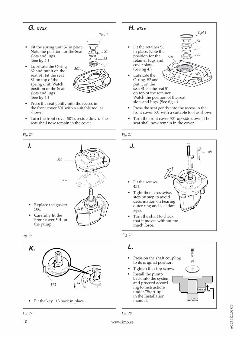
G. xVxx
• Fit the spring unit S7 in place. Note the position for the Seat slots and lugs. (See fig 4.)
• Lubricate the O-ring S2 and put it on the seat S1. Fit the seat S1 on top of the spring unit. Watch position of the Seat slots and lugs. (See fig 4.)
• Press the seat gently into the recess in the front cover 501 with a suitable tool as shown.
• Turn the front cover 501 up-side down. The seat shall now remain in the cover.
• Fit the retainer S3 in place. Note the position for the retainer lugs and cover slots. (See fig 4.)
• Lubricate the O-ring S2 and put it on the seat S1. Fit the seat S1 on top of the retainer. Watch the position of the seat slots and lugs. (See fig 4.)
• Press the seat gently into the recess in the front cover 501 with a suitable tool as shown.
• Turn the front cover 501 up-side down. The seat shall now remain in the cover.
H. xTxx
I.
501
506
• Replace the gasket 506.
• Carefully fit the Front cover 501 on the pump.
J.451
• Fit the screws 451.
• Tight them crosswise, step by step to avoid deformation on bearing outer ring and seal dam-ages.
• Turn the shaft to check that it moves without too much force.
K.
113
• Fit the key 113 back in place.
• Press on the shaft coupling to its original position.
• Tighten the stop screw.
L.
501
S1
S2
S7
501
S1
S2S3
Tool 1 Tool 1
• Install the pump back into the system and proceed accord-ing to instructions under ”Start-up” in the Installation manual.

11
AC
E3 0
620.
06 G
B
www.imo.se
Fig. 29
Pressure relief valve ATTENTION Spring tension.
• Release spring tension by turning set screw 6120 CCW as much as possible.
• Loosen and remove the screws 453.• Separate the valve element from the rear cover
551.• If necessary, replace the gasket 556 and the
O-ring 605.• Reassemble the parts in reverse order. Be careful
to tighten the screws 453 crosswise.• Readjust the valve pressure according to the ”In-
stallation and Start-up Instruction for IMO Low pressure pumps”.
453
612
551
605
556
6120

12 www.imo.se
AC
E3 0
620.
06 G
BIMO AB: P.O. Box 42090, SE 126 14 Stockholm, Sweden Telephone: +46 8 50 622 800, Telefax: +46 8 645 1509
www.imo.se