Main Linac Power - Linear Collider
49
Main Linac Power and Quad / BPM / Wakes Chris Adolphsen July 19-22, 2006 – Vancouver GDE Meeting
Transcript of Main Linac Power - Linear Collider

Main Linac Powerand Quad / BPM / Wakes
Chris Adolphsen July 19-22, 2006 – Vancouver GDE Meeting

ILC Linac RF Unit (1 of ~ 600)
(8 Cavities per Cryomodule)

Pulse Transformer Modulator Status• 10 units have been built, 3 by
FNAL and 7 by industry (PPT with components from ABB, FUG, Poynting).
• 8 modulators are in operation.
• 10 years operation experience.
• Working towards a more cost efficient and compact design.
• FNAL building two more, one each for ILC and HINS programs –SLAC has bulit switching circuits.
HVPS and Pulse Forming Unit
IGCT Stack

New Switch Design Provided by SLAC
Switch Schematic• 10 kV nominal operation • Redundant drive• Independent snubbers

BCD and ACD Modulators (120 kV, 130 A, 1.6 ms, 5 Hz)
Baseline: Pulse Transformer Style Modulator
(~ 2 m Long)
Motivation: Reduce cost, size and weight, improve efficiency and eliminate large oil-filled transformer from tunnel.Will test full prototype in 2006
Alternative: Marx Generator Modulator

Marx Modulator Status• Modulator support structure, backbone, complete. • First 12 kV prototype Marx cell tested at full voltage and current
– Survives ‘spark-down’ tests to simulate shorted load
• Equipotential rings, connection planes complete. • PCB fabrication 50% complete• Air cooled 150 kW test load 50% complete

Stangenes Marx Generatorfor NATO Radar Systems• Peak Operating Voltage: 90 kV• Peak Operating Current: 50-150 A• Pulse Width: 110 microseconds• Duty Cycle: 4.8% (Short Burst)• Continuous Duty Cycle: 2.5% • Pulse Droop: 3% max, 1.5% desirable• Input power: 120 kW• Input voltage: 416 volts AC 60 Hz

Stangenes Marx Generator(Produced 30*3 = 90 kV, 50A, 100 μsec Pulses)

SNS High Voltage Converter Modulator (Unit installed at SLAC)
RECTIFIER TRANSFORMER
AND FILTERSSCR
REGULATOR SWITCHING
BOOST TRANS-
FORMER
HV RECTIFIERAND FILTER NETWORK
13.8KV3Ø
INPUTLINE CHOKE
5th
HARMONICTRAP
7th
HARMONICTRAP
50mH
AØ
BØCØ3Ø
(ON/OFF)
4mH400A
4mH400A
6 EACH
6 EACH
RTNAØ BØ CØ
-HV -HV -HV 10ohm 20mH
.03uF
.03uF
.05uF VMON
HVOUTPUT
RECTIFIER TRANSFORMER
AND FILTERS
SCRREGULATOR HVCM EQUIPMENT
CONTROL RACK
ENERGYSTORAGE
Other AlternativeModulators

Series Switch Modulator(Diversified Technologies, Inc. )
IGBT Series Switch
140kV, 500A switch shown at left in use at CPI
As a Phase II SBIR, DTI is building a 120 kV, 130 A version with a bouncer to be delivered to SLAC at the end of 2006

SLAC FY07 Modulator Program• Continue evaluation of SNS modulator (recently upgraded in a
collaboration with LANL to allow 10 MW klystron operation).
• Establish two new test stands in ESB for DTI and Marx Modulators (start
in FY06).
• Install and evaluate first prototype Marx modulator (run > 2000 hours).
• Install and evaluate DTI modulator (run > 2000 hours).
• Develop a Design-for-Manufacture (DFM) Marx Modulator in
collaboration with LLNL - order parts for two units to be assembled in
house in FY08, but with the circuit board subassemblies and loading let
to commercial vendors.

KlystronsBaseline: 10 MW Multi-Beam Klystrons (MBKs) with ~ 65%
Efficiency: Being Developed by Three Tube Companies in Collaboration with DESY
Thales CPI Toshiba

Status of the 10 MW MBKs• Thales: Four tubes produced, gun arcing problem occured and seemed
to be corrected in last two tubes after fixes applied (met spec). However, tubes recently developed other arcing problems above 8 MW. Thales to build two more without changes and two with changes after problem is better diagnosed.
• CPI: One tube built and factory tested to 10 MW at short pulse. At DESY with full pulse testing, it developed vacuum leak after 8.3 MW achieved –has been repaired and has been tested again.
• Toshiba: One tube built, and after vacuum problem fixed, ran at full spec for one day – was then shipped to DESY where it has run at full power for 200 hours with good efficiency (66%).
• These are vertically mounted tubes – DESY recently asked for bids on horizontally mounted tubes for XFEL (also needed for ILC).

CPI 10 MW MKB Test at DESY in 6/06
• Achieved ~ 8 MW with 1.5 ms
pulses after vacuum fix.
• Limited by low efficiency (53%)
– modulator voltage max’ed.
• During second week of testing,
efficiency dropped to 48%.
• Cause not understood – tube
will be used for component
testing.
D. Sprehn

Alternative Tube Designs
10 MW Sheet BeamKlystron (SBK)
Parameters similar to10 MW MBK
Low Voltage10 MW MBK
Voltage 65 kVCurrent 238AMore beams
Perhaps use a Direct Switch Modulator
5 MW Inductive Output Tube (IOT)
Drive
Out
put
IOT
Klystron
SLAC CPI KEK

SLAC FY07 Klystron Program• Three-prong approach to producing a robust ILC tube
– Order second-generation 10 MW klystrons from CPI and Toshiba.
• Most believe these tubes will work and have long cathode lifetimes (~ 100 khours). However, this forces a larger, more complex design,
– Develop a 10 MW sheet-beam klystron at SLAC
• Considered most risky approach but has the largest potential for cost savings.
– Contract industry to build a higher efficiency, 5 MW, single-beam tube
• Commercial 5 MW tubes are reliable, but have low efficiency (42%).
• Considered a conservative approach, however, will likely require higher voltage modulator, which may decrease reliability of both the tube and modulator.
• CPI and L3 Communications expressed interest in developing this tube.

Plug-compatible ILC RF Source replacement
Large internal surface areas – low cathode current and power densities, low temperatures very robust
No solenoid power required - lighter, and simpler than MBK devices lower costs
Fewer parts than MBK devices – higher yields lower costs
Sheet Beam Klystron Motivation

Beam Transport and RF130 A elliptical beam enters a PCM magnet stack
with cavities inserted between magnets
Lead shielding
Magnetically shielded from outside world
3D Gun simulations give 130 A 40:1 aspect ratio elliptical beam
3D magnet simulations of 30 period structure
3D PIC Code for RF
Electronbeam
PCM Magnetstructure
RF cavity
Size and Beam FocusingILC MBK vs. SBK
SLAC SBK:
921 lbs.122” long28” wide
No solenoid power required!
MBK’s:
~5000 lbs.91” - 98” long35”- 45” wide
Solenoid power4-8 kW

Sheet Beam Schedule(FY06 Work Funded by SLAC)
Jun ‘06 Complete rf beam transport designJul ‘06 Complete gun electrode designAug ‘06 Complete electrical designAug ‘06 Complete mechanical layoutMar ‘07 Mechanical drawingsAug ‘07 Bake-out of first prototypeJan ‘08 Bake-out of second prototype

W-Band Sheet Beam Klystron Program(Not ILC funded)
10 cm
A 91 GHz Sheet-Beam Klystron (74 kV, 3.6 A beam) was built and successfully operated last year with low rf gain.

SLAC L-Band Test Stand• Commercial Thales tubes powered with SNS Modulator
– Have produced 3.3 MW, 1 msec pulses at 5 Hz with a SDI legacy
TH2104U klystron powered with the SNS modulator.
– Recently installed 5 MW TH2104C klystron (DESY testing workhorse).
– Use these tubes to power a
coupler test stand and a
prototype normal-conducting
ILC positron capture cavity.
TH2104U Klystron (red) with Solenoid
(black) Installed in an Oil Tank at ESB

Waveguide Distribution
Coupler Test Stand
Capture Cavity
RF Switch

ILC Positron Capture Cavity Prototype

STF L-Band Source at KEKWaveguide to Distribute Power for
Coupler TestingPulser Unit for a Pulse Transformer Modulator

TTF3 Input Coupler - MultipactingSimulation studies to understand long processing time
500 kW max input power
Track3P
0 0.02 0.04 0.06 0.08 0.1 0.12 0.14 0.160.005
0.01
0.015
0.02
0.025
0.03
0
1469 322
338
351493
shape and cordinate
Cold Bellows
location vs Input power
MP

• Have chosen basic layout of system to test coupler parts
• Setup uses a detachable center conductor and 50 cm long test sections
• Currently building waveguide to coax adaptors
Coupler Processing Studies at SLAC

SLAC FY07 Coupler Program(in collaboration with LLNL)
• Build improved version of TTF3 coupler based on– Results of FY06 tests of coupler components.
– Evaluation of design by SLAC klystron engineers to improve reliability and reduce cost (they developed a new L-band window this year).
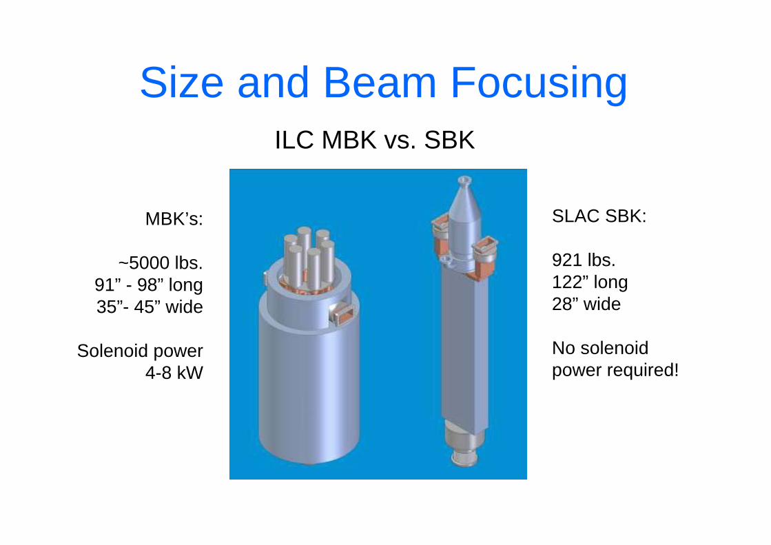
• Setup facility like that at Orsay to assemble and rf process couplers for the cavities being built for ILCTA– Use existing class 1000 clean room and water purification systems
at SLAC (buy small class 100 clean room).
– Use coupler test stand area in ESB to process couplers. EPICS based control system already developed.
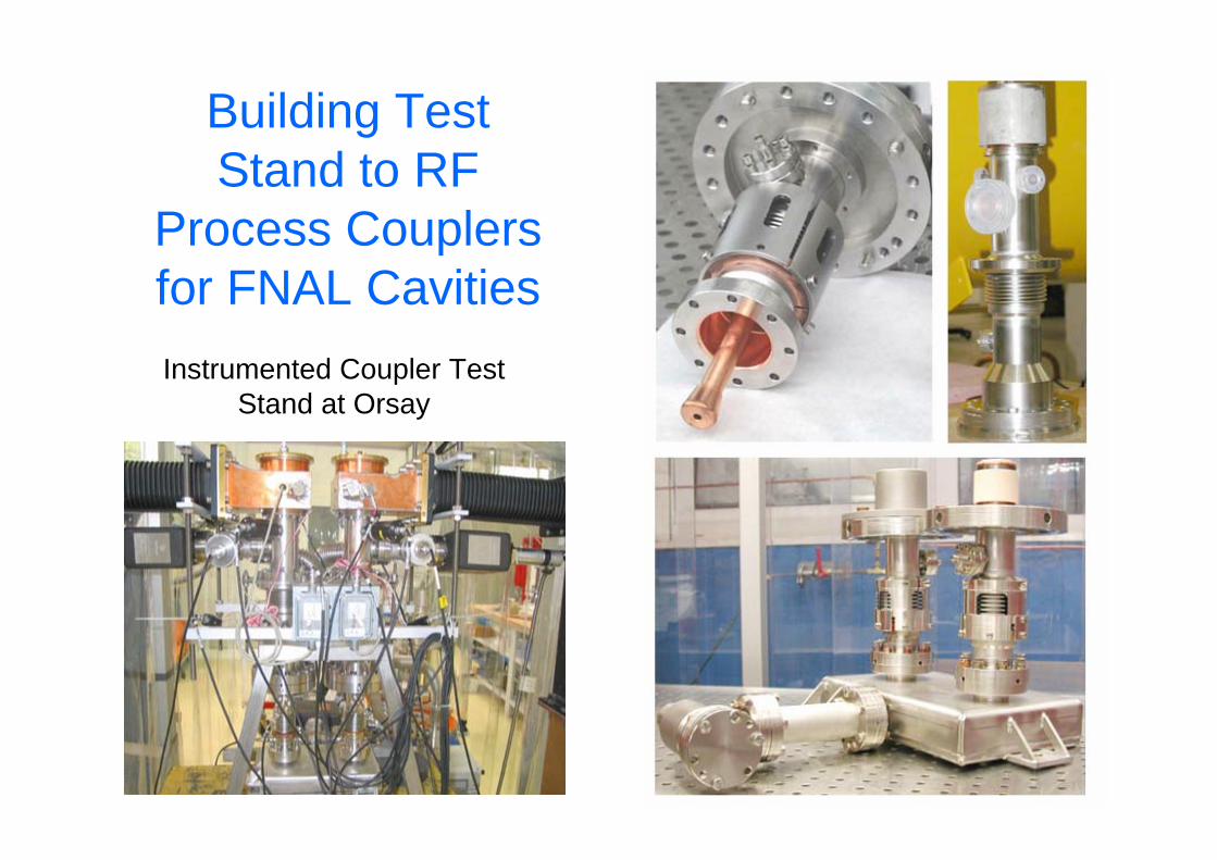
Instrumented Coupler Test Stand at Orsay
Building TestStand to RF
Process Couplers for FNAL Cavities

RF DistributionBaseline choice is the waveguide system used at TTF, which includes off-the-shelf couplers, circulators and 3-stub tuners (phase control).

Need more compact design(Each Cavity Fed 350 kW, 1.5 msec Pulses at 5 Hz)
Two of ~ 16,000 Feeds

Baseline
Alternative Design with No Circulators
And should simplify system(circulators are ~ 1/4 of rf distribution cost)

C. Nantista
Adjustable Tap-Offs Using Mode Rotation
α 2α
Rotatable section with central elliptical region, matched for both polarizations of circular TE11 mode with differing phase lengths.
rotatable joints
load
feed
1
2
3
4
mode rotator

cavity couplers
diagnostic directional couplers
three-stub tuners
flexible waveguide
3-dB hybridsbeam direction
loads
C. Nantista
1.326 m
Proposed RF Distribution Layout• Adjustable power to pairs of cavities• No circulators• Pairs feed by 3 dB hybrids (requires nλ +/- 90 degree
cavity spacing – only 7 mm longer than TDR/BCD spec)

SLAC FY07 RF Distribution Program• Test both high and low power circulators.
• Develop adjustable tap-offs and simple phase shifter, and test at high power.
• Build rf distribution systems for the first two FNAL cryomodules (nλ cavity spacing).– Both would include circulators (needed for beam operation) that could
be removed to test cavity-to-cavity rf coupling without them.
– Second would include a simpler phase shifter in place of 3-stub tuner.
– The TTF4 cryomodules would hopefully not need circulators.
• Develop methods to weld waveguides together to avoid costly and unreliable flanges.

ILC RF Distribution System

Al Waveguide Test Welds

XFEL Prototype Distribution Systems
Tree-Like
TTF-Like


Replace 3-Stub Tuner with Phase Shifter
V. Katalev, S Choroba
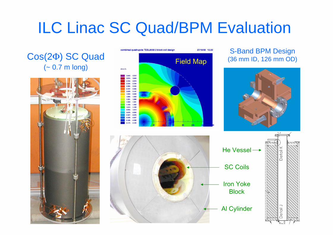
Cos(2Φ) SC Quad(~ 0.7 m long)
S-Band BPM Design(36 mm ID, 126 mm OD)Field Map
Al Cylinder
Iron YokeBlock
SC Coils
He Vessel
ILC Linac SC Quad/BPM Evaluation

Cryostat and Cryogenic System
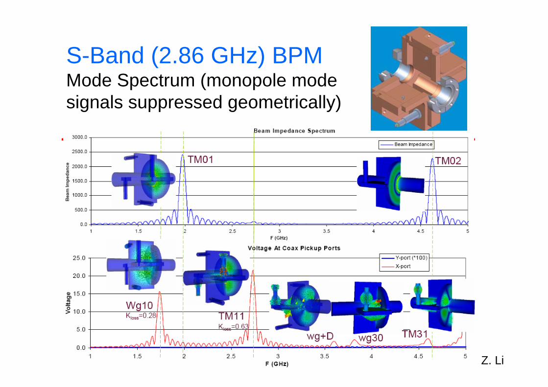
S-Band (2.86 GHz) BPMMode Spectrum (monopole modesignals suppressed geometrically)
Z. Li

Recent BPM Triplet Results(0.5 micron resolution, 1.4e10 electrons, Q of 500 for clean bunch separation)

L-Band Preliminary Design
• Selective coupling scheme• Hidden coax pickup from the beam• Easily cleanable• Preliminary parameters:
– Beampipe radius: 39 mm– Radial dimension: ~ 250 mm– Longitudinal dimension: ~100 mm– Will fit into the present footprint – Thermal noise limited resolution: ~6 nm for a
20-mm cavity gap

Cavity Dipole Mode Q and Frequency Spread
Ideal Cavity
Qext
shift
splitscatter
Effects of cavity deformations:Mode splitting is 100s of kHz(10s of kHz in ideal cavity), Mode frequency is shifted by as much as few MHz,Qext scatter towards high side - may lead to dangerous modes.
Shape determination:Solve an inverse problem to findcavity TRUE shape Use measurements from TESLAcavity data bank as input Goal to identify sensitivity ofcritical dimensions affecting Qe
2nd Band
Stability threshold(R/Q) x Qe

TESLA Cavity – Wakefields (T3P)
T3P
1.75 M quadratic elements, 10 M DOFs, 47 min per nsec on Seaborg 1024 CPU with 173 GB memory – CG and incomplete Cholesky preconditioner

0123456789
128 256 512 1016Number of cpu's
Spe
edup
nor
mal
ized
as
1fo
r 128
cpu
's
Phoenix IdealT3P – Code has been improved
to allow scalability to more than 1000 CPUs for a medium-size problem with close to linear speedup on NCCS’s Phoenix
Towards Petascale Simulations Omega3P - A nonlinear eigensystem with > 15 million of DOFs was solved within 10 hours on 768 CPUs with 276 GB memory on NERSC’s Seaborg as a 1st step towards modeling an entire cryomodule:
4-cavity Structure

RF Source Summary• Marx Modulator approach looks very promising.
• Toshiba 10 MW klystron appears robust. Sheet-beam
approach likely to reduce costs.
• Both SLAC and DESY working on lower cost rf
distribution systems.
• SLAC and KEK now have working L-Band test stands.
• SLAC beginning program to understand TTF3 coupler
processing limitations and improve design.