
M2 Antenna Systems, Inc. Model No: AE2000 MANUALS/AZEL1000/FGAE2000MAN00.pdf · The New AE2000S was...
12
M2 Antenna Systems, Inc. 4402 N. Selland Ave. Fresno, CA 93722 Tel: (559) 432-8873 Fax: (559) 432-3059 Web: www.m2inc.com ©2016 M2 Antenna Systems Incorporated 071/16 Rev.00 M2 Antenna Systems, Inc. Model No: AE2000
Transcript of M2 Antenna Systems, Inc. Model No: AE2000 MANUALS/AZEL1000/FGAE2000MAN00.pdf · The New AE2000S was...

M2 Antenna Systems, Inc. 4402 N. Selland Ave. Fresno, CA 93722 Tel: (559) 432-8873 Fax: (559) 432-3059 Web: www.m2inc.com
©2016 M2 Antenna Systems Incorporated 071/16 Rev.00
M2 Antenna Systems, Inc. Model No: AE2000

TABLE OF CONTENTS
SECTION ................................................. ……PAGE SYSTEM OVERVIEW ............................................... 1-8 Azimuth Overview ........................................ 2 Elevation Overview ........................................ 2 System Un-Packing ....................................... 4 Base Details .................................................. 5-8 SETUP & CONFIGURATION .................................... 9 Powering the System ..................................... 9 Setting and Changing Limit Switches .............. 10 Internal Cable Routing Details ....................... 11 Polarization ................................................... 12 SYSTEM OPERATION & DEFINITIONS…………………..28 Home Operation……………………………………..28-29 Standby Command ........................................ 30 Velocity Command ........................................ 31 Position Command ........................................ 32 Stow Command ............................................ 33 Calibration & Track Mode ............................... 34 Operation Status ........................................... 35 Operations Control ........................................ 36 Faults & Status ............................................. 37 Configuration Changes .................................. 38 Parameter Graph Displays .............................. 39 Azimuth Offset .............................................. 40 Elevation Offset ............................................ 41 Offset Adjustment ......................................... 42 ACU Upgrades / Reload ................................. 43 Interface Control Document ........................... 44 TROUBLESHOOTING………………………………………..45-46 WARRANTY ........................................................... 47

SYSTEM SPECIFICATIONS & FEATURES
Model ....................................... AE2000S Max Overturn ............................. 6700 Lb. Ft. Max Load ................................... 700 Lb. Gear Box ................................... Cycloidal Ratio .......................................... 774:1 Backlash .................................... 0.01 Degrees Max Velocity .............................. 20 Degrees Per Second
Max Acceleration ....................... 20 Degrees Per Second AZ Travel ................................... 170 Degrees Adjustable EL Travel ................................... 180 Degrees Adjustable Limits ......................................... Soft and Hard Limits Point Accuracy ........................... 0.05 Interface ..................................... RS 232 / Ethernet Communication Protocol ........... Open Architecture
The New AE2000S was designed for one of our High End Commercial customers. Built with M2 Antenna Systems build-ing block configuration, the AE2000S will handle 8 to 16 foot parabolic dishes for S-Band, X-Band and KU-Band fre-quencies. The AE2000S boasts large 65 pound gear boxes with NEMA 34 motors and safety brakes. The Azimuth axis unit is capable of 700+ degrees of movement with our custom slip ring limit mechanism which allows internal cable wrapping management. The Elevation unit is capable of 180 degrees of movement. Removable access panels can be drilled for your specific cable connections. Custom riser bases can be built based upon your dish diameter. All connec-tions points on the AE2000S are O-ring sealed via custom enclosures or panels. For more robust configurations, bolt on exoskeleton can be added.
UNIQUE FEATURES: 1. Cycloidal gearboxes on both axis, resulting in the ability to take high shock loads caused by Mother nature. 2. Programmable holding brakes on both axes that are engaged even when the system is not powered. 3. Stacked azimuth bearing featuring a 10in. diameter upper bearing for the ability to handle high overturn mo-
ments. 4. Unique tapered octagon concept used on the main azimuth base gives the system a sleek look, while keeping
the load as close to over the center of axis as possible but spreading the load at the base. 5. Large multiple sealed access covers on both Azimuth and Elevation bodies, gives easy access to motors, limit
switches, cable loops or housed internal components. 6. Azimuth gearbox with thru the center construction with a pass thru of 2" in diameter, allows cables to be passed
thru the azimuth gear box without the use of a rotary joint. 7. Azimuth limit switch system using a unique slip ring system giving up 700 degrees of axis rotation before switch
engagement. 8. Large envelope in azimuth base for cable management, with a large modifiable sealed access cover for RF or
control wire exiting. 9. A modifiable sealed side cover at the Elevations rotating axis on the counterbalance arm, gives the ability run
RF cables or control wires into the base, up thru the azimuth, into the Elevation housing, and out the sealed side cover and on to external housings or to the feed.
10. Accessory mounts can be added to support an external NEMA rated box to house amplifiers, preamps, downconverters or other needed components.
11. Base extensions are available to raise the Azimuth base to desired heights to accommodate different dish diam-eters.
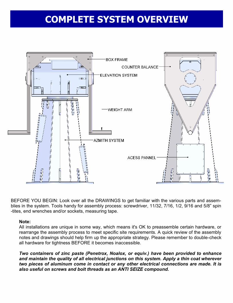
COMPLETE SYSTEM OVERVIEW
BEFORE YOU BEGIN: Look over all the DRAWINGS to get familiar with the various parts and assem-blies in the system. Tools handy for assembly process: screwdriver, 11/32, 7/16, 1/2, 9/16 and 5/8” spin-tites, end wrenches and/or sockets, measuring tape. Note: All installations are unique in some way, which means it's OK to preassemble certain hardware, or
rearrange the assembly process to meet specific site requirements. A quick review of the assembly notes and drawings should help firm up the appropriate strategy. Please remember to double-check all hardware for tightness BEFORE it becomes inaccessible.
Two containers of zinc paste (Penetrox, Noalox, or equiv.) have been provided to enhance
and maintain the quality of all electrical junctions on this system. Apply a thin coat wherever two pieces of aluminum come in contact or any other electrical connections are made. It is also useful on screws and bolt threads as an ANTI SEIZE compound.

COMPLETE SYSTEM DIMENSIONS
BOX FRAME DETAIL BASE PAD DETAIL
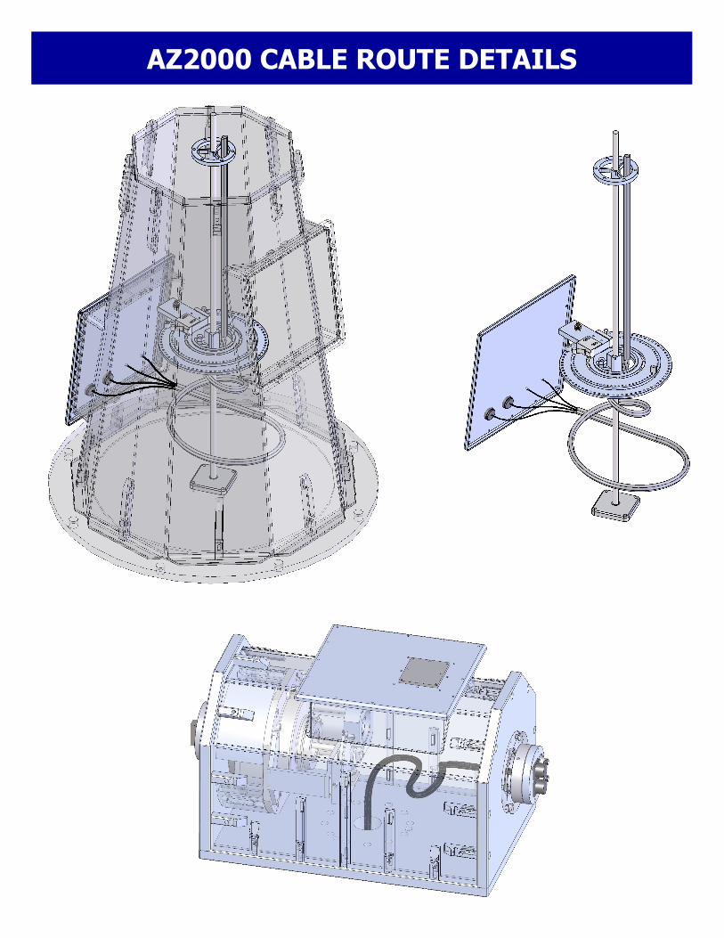
AZ2000 CABLE ROUTE DETAILS

AZ2000 LIMIT SWITCH DETAILS

AZEL2000 CABLE ROUTE DETAILS

EL2000 LIMIT SWITCH DETAILS

UN-PACKING COMPLETE SYSTEM

AZEL2000 PARTS & HARDWARE LIST DESCRIPTION QTY AZ-2000 System .......................................................................................... 1 EL-2000 System with Box Frame & Balance Arms ...................................... 1 Counter Balance Weight, 15lbs. (M2AAE1627) ........................................... 8 Weight Locking Collar (M2AAE1601) ........................................................... 2 Control Cable Assembly, 50’ ........................................................................ 2 Limit Switch Dog Block ................................................................................. 1 RS-32 Cable Connector ............................................................................... 1 RJ-45 Cable Connector ................................................................................ 1 HARDWARE Bolt, 3/4-10 x 3”, Hex Head, ZNC ................................................................. 8 Lock Washer, 3/4”, ZNC ............................................................................... 8 Nut, 3/4-10, ZNC .......................................................................................... 8 Bolt, 3/8-16 x 3/4”, Square Head, S.S .......................................................... 2 Screw, 8-32 x 3/4, Pan Head, S.S. ............................................................... 1 Screw, 8-32 x 3/8, Pan Head, S.S. ............................................................... 60
□ (OPTIONAL) 12’ DISH KIT (PRI-12-19)
DESCRIPTION QTY
Bolt, 3/8-16 x 1”, Hex Head, S.S .................................................................. 6 Flat Washer, 3/8”, S.S .................................................................................. 6 Lock Washer, 3/8”, S.S ................................................................................ 6
□ (OPTIONAL) HOUSING MOUNTING KIT
DESCRIPTION QTY
Mounting Bracket (Left) ................................................................................ 1 Mounting Bracket (Right) .............................................................................. 1 Bolt, 3/8-16 x 1-1/2”, Hex Head, S.S ............................................................ 6 Bolt, 3/8-16 x 1”, Hex Head, S.S .................................................................. 2 Locking Nut, 3/8-16,S.S. .............................................................................. 8

12 Month Limited Warranty Information
This warranty gives you specific legal rights. You may also have other rights which will vary from state to state or province to province. M2 warrants the 2-Axis Positioner unit against defects in material and workmanship for a period of 12 months from date of purchase. During the warranty period, M2 will, at its option, either repair or replace products or components which prove to be defective. The warranty shall not apply to defects or damage resulting from: • Improper or inadequate maintenance by user • Improperly prepared installation site • Unauthorized modifications or misuse • Accident, abuse, or misapplication • Normal wear M2 specifically does not warrant this product for any direct, indirect, consequential, or incidental damages arising from the use or inability to use the product. Some states or provinces do not allow the exclusion or limitation of liability for consequential or incidental damages so the above limitation may not apply. In the event repair or replacement are necessary, purchaser shall contact M2 for return authorization. In many cases this contact can simplify and expedite the repair / replacement process and help reduce costs and downtime. The purchaser shall be responsible for packing the product properly for return and for charges to ship the product to M2. Always include with the shipment, a statement detailing the problem / failure and any other pertinent observations. Insuring the product for shipment is recommended. Use the orig-inal packing materials whenever possible. M2 is responsible for charges (in the United States) to re-turn the repaired / replacement product only where warranty service is involved.
M2 Antenna Systems, Inc. 4402 N. Selland Ave. Fresno, CA 93722 (559) 432-8873 Fax (559) 432-3059 Web: www.m2inc.com


![[XLS] · Web viewSheet3 Sheet2 Feeder.P Feeder.E Antenna Antenna (2) 6 5 4 APPURTENACES $ Equivalent Projected Area and Force Coefficient Panel Antenna m kg m2 K741989 Antenna Drag](https://static.fdocuments.net/doc/165x107/5ab1f7bf7f8b9a284c8d240f/xls-viewsheet3-sheet2-feederp-feedere-antenna-antenna-2-6-5-4-appurtenaces.jpg)


