M2 Antenna Systems, Inc. Model No: RC2800PXEL MANUALS/RC2800 SERIE… · · 2015-05-28M2 Antenna...
23
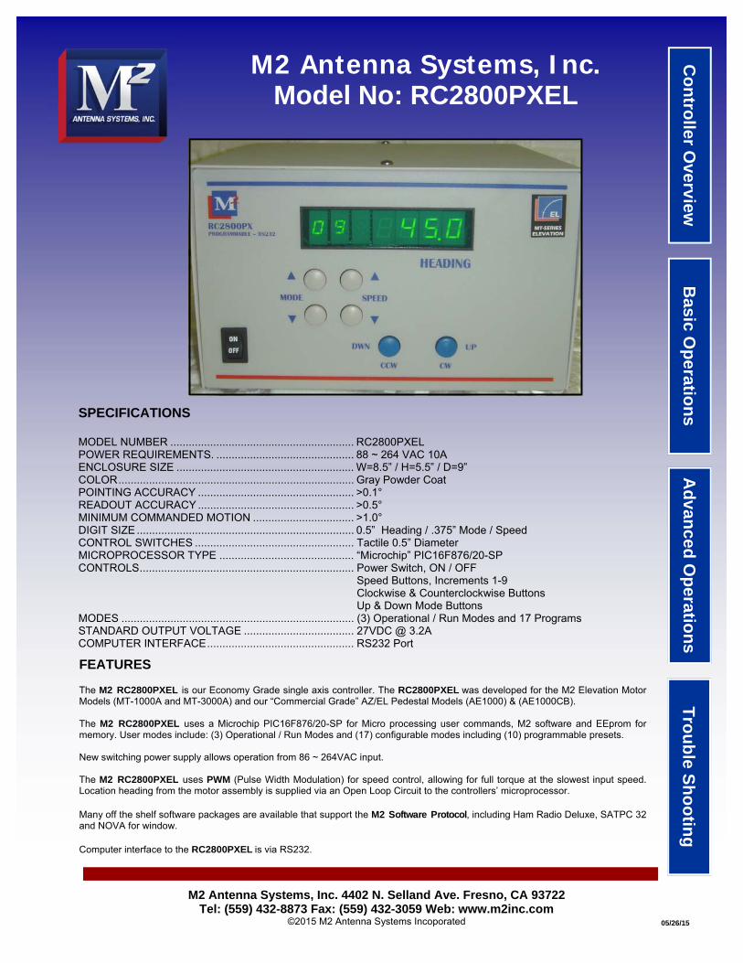
M2 Antenna Systems, Inc. Model No: RC2800PXEL SPECIFICATIONS MODEL NUMBER ............................................................ RC2800PXEL POWER REQUIREMENTS. ............................................. 88 ~ 264 VAC 10A ENCLOSURE SIZE .......................................................... W=8.5” / H=5.5” / D=9” COLOR ............................................................................. Gray Powder Coat POINTING ACCURACY ................................................... >0.1° READOUT ACCURACY ................................................... >0.5° MINIMUM COMMANDED MOTION ................................. >1.0° DIGIT SIZE ....................................................................... 0.5” Heading / .375” Mode / Speed CONTROL SWITCHES .................................................... Tactile 0.5” Diameter MICROPROCESSOR TYPE ............................................ “Microchip” PIC16F876/20-SP CONTROLS...................................................................... Power Switch, ON / OFF Speed Buttons, Increments 1-9 Clockwise & Counterclockwise Buttons Up & Down Mode Buttons MODES ............................................................................ (3) Operational / Run Modes and 17 Programs STANDARD OUTPUT VOLTAGE .................................... 27VDC @ 3.2A COMPUTER INTERFACE ................................................ RS232 Port M2 Antenna Systems, Inc. 4402 N. Selland Ave. Fresno, CA 93722 Tel: (559) 432-8873 Fax: (559) 432-3059 Web: www.m2inc.com ©2015 M2 Antenna Systems Incoporated 05/26/15 FEATURES The M2 RC2800PXEL is our Economy Grade single axis controller. The RC2800PXEL was developed for the M2 Elevation Motor Models (MT-1000A and MT-3000A) and our “Commercial Grade” AZ/EL Pedestal Models (AE1000) & (AE1000CB). The M2 RC2800PXEL uses a Microchip PIC16F876/20-SP for Micro processing user commands, M2 software and EEprom for memory. User modes include: (3) Operational / Run Modes and (17) configurable modes including (10) programmable presets. New switching power supply allows operation from 86 ~ 264VAC input. The M2 RC2800PXEL uses PWM (Pulse Width Modulation) for speed control, allowing for full torque at the slowest input speed. Location heading from the motor assembly is supplied via an Open Loop Circuit to the controllers’ microprocessor. Many off the shelf software packages are available that support the M2 Software Protocol , including Ham Radio Deluxe, SATPC 32 and NOVA for window. Computer interface to the RC2800PXEL is via RS232. Trouble Shooting Advanced Operations Basic Operations Controller Overview
Transcript of M2 Antenna Systems, Inc. Model No: RC2800PXEL MANUALS/RC2800 SERIE… · · 2015-05-28M2 Antenna...
M2 Antenna Systems, Inc. Model No: RC2800PXEL
SPECIFICATIONS MODEL NUMBER ............................................................ RC2800PXEL POWER REQUIREMENTS. ............................................. 88 ~ 264 VAC 10A ENCLOSURE SIZE .......................................................... W=8.5” / H=5.5” / D=9” COLOR ............................................................................. Gray Powder Coat POINTING ACCURACY ................................................... >0.1° READOUT ACCURACY ................................................... >0.5° MINIMUM COMMANDED MOTION ................................. >1.0° DIGIT SIZE ....................................................................... 0.5” Heading / .375” Mode / Speed CONTROL SWITCHES .................................................... Tactile 0.5” Diameter MICROPROCESSOR TYPE ............................................ “Microchip” PIC16F876/20-SP CONTROLS ...................................................................... Power Switch, ON / OFF Speed Buttons, Increments 1-9 Clockwise & Counterclockwise Buttons Up & Down Mode Buttons MODES ............................................................................ (3) Operational / Run Modes and 17 Programs STANDARD OUTPUT VOLTAGE .................................... 27VDC @ 3.2A COMPUTER INTERFACE ................................................ RS232 Port
M2 Antenna Systems, Inc. 4402 N. Selland Ave. Fresno, CA 93722 Tel: (559) 432-8873 Fax: (559) 432-3059 Web: www.m2inc.com
©2015 M2 Antenna Systems Incoporated 05/26/15
FEATURES The M2 RC2800PXEL is our Economy Grade single axis controller. The RC2800PXEL was developed for the M2 Elevation Motor Models (MT-1000A and MT-3000A) and our “Commercial Grade” AZ/EL Pedestal Models (AE1000) & (AE1000CB). The M2 RC2800PXEL uses a Microchip PIC16F876/20-SP for Micro processing user commands, M2 software and EEprom for memory. User modes include: (3) Operational / Run Modes and (17) configurable modes including (10) programmable presets. New switching power supply allows operation from 86 ~ 264VAC input. The M2 RC2800PXEL uses PWM (Pulse Width Modulation) for speed control, allowing for full torque at the slowest input speed. Location heading from the motor assembly is supplied via an Open Loop Circuit to the controllers’ microprocessor. Many off the shelf software packages are available that support the M2 Software Protocol, including Ham Radio Deluxe, SATPC 32 and NOVA for window. Computer interface to the RC2800PXEL is via RS232.
Tro
ub
le Sh
oo
ting
A
dvan
ced O
peratio
ns
Basic O
peratio
ns
Co
ntro
ller Overview

TABLE OF CONTENTS
Cover Page ............................................................................. 1
Table of Contents .................................................................... 2
Front Panel Overview .............................................................. 3
Rear Panel Overview .............................................................. 4
Basic Operations / Run Mode Description .............................. 5
Program Mode Definitions and Explanations .......................... 6,7
Elevation System Without Limits (MT-1000A/MT-3000A) ....... 8
Elevation System Configuration With Limits (MT-1000A) ........ 9
Elevation System Configuration With Limits (MT-3000A) ........ 10
Connections and Start Up ....................................................... 11
Physical Limit Switch Pre Test ................................................ 12
Advanced Operations / Computer Control .............................. 13
Advanced Operations / Software Commands ......................... 14,15
Troubleshooting ...................................................................... 16,17
RC2800PXAZ/EL Control Unit Wiring ..................................... 18
RC2800PXAZ/EL Power Conditioning Schematic .................. 19
Positioner to be used with RC2800PXEL ................................ 20
Suggested Rotator Cable (RCS-1812) .................................... 21
RC2800PXEL Packing ............................................................ 22
Warranty Information............................................................... 23
Page 2

FRONT PANEL CONTROL OVERVIEW
Digital Display
Speed Buttons Mode Buttons
Power Switch
Control Buttons
ON/OFF (POWER): This button controls AC power to the control unit. UNDERSTANDING YOUR DIGITAL DISPLAY:
Digital Display in Degrees
1 4 0 l 1 0
Mode # Speed Info Digit
FIGURE 1
Digital Display in Degrees
2 5 0 0 2
Info Digit
FIGURE 2
“Cal” Function
c a l 0 p
FIGURE 3
Preset # 20-29
CCW/DWN Segments
“Cal” Function
Page 3
DISPLAY EXPLANATION: In Mode “0” and “1” the first digit is the Mode # and the second digit is Speed (Figure 1). The third digit in the display in Mode “0” and “1”, is the Info Digit. This is primarily used when approaching a limit “L” or a “-” indicating below zero in Elevation. (Figure 1). In Mode “2” the first and second digit become your preset numbers from 20-29 (Figure 2). In “PO Cal” Mode the first two digits indicate the Mode #. The fourth digit or Info Digit indicates CCW/DWN Segments in auto travel and digits 5,6 and 7 indicate the “Cal” function (Figure 3). MODE BUTTONS: The MODE buttons are used to cycle through and select among (3) operational or RUN modes, 17 PROGRAM modes and 10 PRESETS. See RUN MODES and PROGRAM MODE details following this section. SPEED BUTTONS: The SPEED buttons control the positioner’s rate of speed in relative increments. “1” is the slowest speed, “9” is the fastest. The top button increases the speed, the lower button decreases the speed. The lowest speed available DEFAULTS to “1”, but can be set to any number between “1” and “9”. Speeds can be altered for travel in any of the run modes. CONTROL BUTTONS: The “CW” and “CCW” or “UP” or “DOWN” buttons, activate the positioners’ direction in MODE “0”, MODE “1” and MODE “2”. These buttons are also used for “CAL” or “Auto Cal.”

REAR PANEL OVERVIEW
“AC IN” The supplied (3) prong AC cord plugs into this socket. Connect to a reliable 115 or 230 VAC source. The Main AC input has been designed to filter slight changes to incoming AC. “VAC” SELECT The voltage selection switch is no longer used on this model. We have upgraded from a transformer to a switching power supply that operates from 86 ~ 264VAC. “FUSE” The “Motor Protection” fuse provides electrical protection to the positioner. Replace this fuse with a 125VAC 3A fuse. “RS232” INTERFACE PORT This is a standard (9) pin female (DB9) connector for linking to a computer for automated control. Do not use a null modem cable for this application. TERMINAL STRIP The (6) position terminal strip, serves as your multi-conductor cable interface to the positioner unit. The cable supplies power and data from the positioner. A ground stud is provided at the right end of the terminal for shielded cables. DISCONNECT THE AC POWER CORD WHEN CONNECTING CABLE LEADS.
TERMINAL NUMBER FUNCTION SUGGESTED COLOR MINIMUM WIRE GAUGE
#1 MOTOR +27VDC (DWN) BLACK 16 AWG
#2 MOTOR +27VDC (UP) WHITE 16 AWG
#3 (NOT USED)
#4 (NOT USED)
#5 REED SWITCH DC + ORANGE 24 AWG
#6 REED SWITCH RETURN BLUE 24 AWG
GROUND STUD CASE GROUND BARE NA
((6) POSITION TERMINAL STRIP ASSIGNMENTS
WIRING AND INSTALLATION HINTS: Poor quality wiring or cable and wiring errors are the major cause of operational failure. Occasionally this even causes positioner or control box failure. For short runs of 100 feet or less, the wire sizes above are adequate. For runs over 100 feet, we suggest a multi conductor cable manufactured for our Azimuth and Elevation systems called RCS-1812. This is a 4 conductor cable with (2) 14 gauge wires for motor leads, (2) 22 gauge shielded lines for reed switch lines and a single drain wire for grounding.
Page 4
Terminal Strip
Motor Protection

BASIC OPERATIONS / RUN MODE DESCRIPTIONS
RUN MODES: Modes 0, 1 and 2 are all run modes capable of activating the positioner in both the CCW / DWN and CW / UP direction.
MODE 0 = MANUAL OPERATION MODE: Pushing the CCW button activates the positioner in the Counter Clockwise direction, and the Heading count will go down. Pushing the CW button activates the positioner in the Clockwise direction, and the Heading count will go up. Pressing the UP button activates a specific positioner in the Upward direction and the Heading count will go up. Pressing the DWN button activates the positioner in the Downward direction and the Heading count will go down. The positioner runs while CCW / DWN or CW / UP button is depressed, ramping up from minimum programmed speed to the maximum (9) and then again ramping down to speed (1). When reversing direction, there is a 2-3 second delay before the positioner is activated. This delay reduces stress on your antenna and positioner. NOTE: Rotation direction, i.e., CCW / DWN or CW / UP is defined as if you are looking down on the positioner / antenna from above. There is NO automatic speed ramp down when operating in Mode 0 except as you approach a limit. Small movements of positioner may not allow full speed to be reached.
MODE 1 = COMPUTER CONTROL OR MANUAL PRESET MODE: Computer control or Manual preset mode. When computer control is activated, a “1” automatically appears in the MODE # location on the display. Manually the CW / UP and CCW / DOWN buttons can be used to select a heading on display from the full range of rotation. After the button is released, there is a short delay before the positioner activation allowing time to adjust or “bump” your selection. As the positioner begins to run, the speed ramps up from the minimum programmed speed to the maximum. As the target heading is approached, the speed ramps down to stop. The positioner may then “bump” several times until within .5 degrees of preset. To STOP or cancel a preset any time, touch either mode button.
MODE 2 = PROGRAMMABLE PRESET MODE: Press the CW / UP and CCW / DOWN buttons to cycle through 10 preset headings you program in Modes 20-29. Heading selections are shown on the display. After a short pause, allowing you to confirm your selection, the positioner will proceed to the displayed heading in the same manner as MODE #1. Typically, these presets are programmed for frequently used headings and or stow positions for parking or extreme weather. To stop or cancel a preset in mid travel, touch either mode button.
Page 5

PROGRAM MODES: Modes P1-P6 are Program modes that permit entering, changing, or reviewing programmed system parameters. Program modes P20 through P29 are reserved for 10 preset headings.
USING PROGRAMMABLE MODES: Press and hold the upper mode button for 3 seconds. The display will change to mode P20. P20 is the first of your 10 PRESET headings. Press the lower mode button each time to scroll through modes P6, P5, P4, P3, P2, P1, AND PO CAL. Now press the upper mode button each time to scroll back up through the program modes. The display will show current mode setting. The Factory Defaults are listed below. Most of the time these will never be changed. To program or change any setting, depress the CW / UP or CCW / DOWN buttons until the desired setting is displayed. Change anything or everything in the program mode except P6 and save just once. Note: During programming, the numbers change slowly at first then speed up. Releasing the button and pressing it again resets the process of slow to fast number change. PROGRAM P6: Used to correct your heading of the antenna or array when the unit was not setup up correctly during installation or if your mast has slipped in high wind. To change to a new heading, press the CCW / UP or CW / DOWN button until the desired corrected heading is achieved. Press and hold the lower button for 3 seconds to save. Your new heading will appear in Mode 0. Note: The use of this mode can cause loss of over travel. PROGRAM P5: Speed / Ramp function. The number (1) is the minimum Speed and Ramp setting. The number (1) gives you full speed and ramp control. Note: When trouble shooting a faulty operation, to get good motor voltage and reed switch readings, it is helpful to temporarily set the speed to (9). This eliminates motor pulses and give a steady DC reading for your DVM. PROGRAM P4: The Pulse Divide Ratio is the number of pulses used for the gear ratio of a given positioner. Use the Pulse Divide Ratio chart below for the correct number for your positioner. Note: In most cases the Pulse Divide Ratio will be pre-determined from the factory based upon the positioner you have ordered.
PROGRAM MODE DEFINITIONS AND EXPLANTIONS
AZIMUTH MODEL PULSE DIVIDE RATIO ELEVATION MODEL PULSE DIVIDE RATIO
OR2800PX 3960 MT-1000A 13200
AZ1000 13200 EL1000 13200
MT-3000A 37500
PROGRAM P3: Positioner Orientation Type. This Azimuth configuration determines the positioners’ spectrum or travel of use. A “North” stop configuration would be used when 360° of travel is necessary with primarily a southern exposure is needed. A “South” stop configuration would be used when 360° of travel is necessary with a primarily a northern exposure is needed. Note: In most cases the positioner orientation type will be set to “North” stop from the factory. More detailed information can be found in the System Configuration section of this manual. PROGRAM P2: The (Upper or UP) electronic limit for Elevation. The CW (Clockwise) Limit for Azimuth. In most cases these limits will be preset from the factory. More detailed information can be found in the System Configuration section of this manual. PROGRAM P1: The (Lower or DOWN) electronic limit for Elevation. The CCW (Counter Clockwise) Limit for Azimuth. Limit for Azimuth. In most cases these limits will be preset from the factory. More detailed information can be found in the System Configuration section of this manual.
Page 6

PROGRAM PO CAL: *A Limit Switch Kit must be installed on the MT-1000A or MT-3000A Elevation units to use the Automatic Calibration Procedure. Automatic Calibration of your positioner when physical limits are in-stalled. To start the automatic calibration process, press and hold the upper mode button for 3 seconds. Pro-gram P20 will appear as the first program mode. Now press the lower mode button seven times until “PO Cal” appears on the display. Press and hold the lower mode button for 3 seconds and the automatic calibration will start by showing the small LED segments just left of the “C” moving in the CCW direction. Once the posi-tioner has completed its automatic calibration it will stop and a new heading will be present on the display. More detailed information can be found in the System Configuration section of this manual. PROGRAM P20-P29: User programmable preset headings. To program your favorite headings, press and hold the upper mode button for 3 seconds and the controller will go to program P20. *Note: We have pre-programmed the presets at
PROGRAM MODE DEFINITIONS AND EXPLANTIONS
20 0
21 10
22 20
23 30
24 40
25 50
26 60
27 70
28 80
29 90
EL PRESETS (FACTORY)
20
21
22
23
24
25
26
27
28
29
EL PRESETS (NEW USER)
20 30
21 60
22 90
23 120
24 160
25 210
26 255
27 285
28 315
29 340
AZ PRESETS (FACTORY)
20
21
22
23
24
25
26
27
28
29
AZ PRESETS (NEW USER
Once P20 appears, press the CCW / DOWN or CW / UP buttons until you reach the desired heading. Now press the upper mode button again and P21 will appear. Use the CCW / DOWN or CW / UP buttons until you reach the desired heading. Use the same process to program all presets. Once all of the presets are programmed, press and hold the lower mode button for 3 seconds to save.
Page 7

ELEVATION SYSTEM WITHOUT PHYSICAL LIMITS
MT-1000A or MT-3000A ELEVATION OPTION #1
Characteristics: Elevation (90) Spectrum of use: 0° to 90° Program P1 setting: 5° (Down Limit) Program P2 setting: 95° (Up Limit) OVERVIEW: This Elevation configuration is used as a standard throughout the industry and may be used when 0° to 90° of travel is necessary. Note the position of the electrical limits. This configuration provides 5° of over travel on both ends of the spectrum travel. SETUP: Set Program P1 to 5° (Down Limit) Set Program P2 to 95° (Up Limit)
MT-1000A OR MT-3000A ELEVATION OPTION #2
Characteristics: Elevation (180) Spectrum of use: 0° to 180° Program P1 setting: 5° (Down Limit) Program P2 setting: 185° (Up Limit) OVERVIEW: This Elevation configuration is used as a standard throughout the industry and may be used when 0° to 90° of travel is necessary. Note the position of the electrical limits. This configuration provides 5° of over travel on both ends of the spectrum travel. Note: Always watch for mechanical interference, there may be limitations of the overall range above 125°. SETUP: Set Program P1 to 5° (Down Limit) Set Program P2 to 185° (Up Limit)
MT-1000A OR MT-3000A WITHOUT PHYSICAL LIMITS: The RC2800PXEL needs to be configured for a spectrum of use and position limits. The programmable limits in the RC2800PXEL control, give the ability to specify the amount of travel around a spectrum of use. When using the RC2800PXEL and MT-1000A or MT-3000A elevation systems without physical limit switches the setup is simplified. No matching of the DOWN electrical or physical limit is necessary and the orientation of the elevation system is less critical. The RC2800PXEL relies on the programmed electrical limits. Without physical limits there will be no safety in the case of a control box failure and “PO Cal” will not be available. Below we have provided a visual explanation complete with suggested electrical limits.
Page 8

ELEVATION SYSTEM WITH PHYSICAL LIMITS (MT-1000A)
MT-1000A ELEVATION OPTION #1 Characteristics: Elevation (90) Spectrum of use: 0° to 90° Program P1 setting: 5° (Down Limit) Program P2 setting: 95° (Up Limit) OVERVIEW: This Elevation configuration is used as a standard throughout the industry and may be used when 0° to 90° of travel is necessary. Note the position of the physical limit switches, the Up physical limit is on the outside of the electrical limit. The Down physical and electrical limit is matched to act as a reference during the use of the “PO Cal” function. Ultimately this configuration provides safety when and if a control box may fail. SETUP: Set Program P1 to 5° (Down Limit) Set Program P2 to 95° (Up Limit)
MT-1000A ELEVATION OPTION #2 Characteristics: Elevation (180) Spectrum of use: 0° to 180° Program P1 setting: 5° (Down Limit) Program P2 setting: 185° (Up Limit) OVERVIEW: This Elevation configuration is used as a standard throughout the industry and may be used when 0° to 180° of travel is necessary. Note the position of the physical limit switches, the Up physical limit is on the outside of the electrical limit. The Down physical and electrical limit is matched to act as a reference during the use of the “PO Cal” function. Ultimately this configuration provides safety when and if a control box may fail. Note: Always watch for mechanical in-terference, there may be limitations of the overall range above 125°. SETUP: Set Program P1 to 5° (Down Limit) Set Program P2 to 185° (Up Limit)
MT-1000A CONFIGURATION: The RC2800PXEL needs to be configured for a spectrum of use and position of limits. The programmable limits in the RC2800PXEL control, give the ability to specific the amount of travel around a spectrum of use. When using the optional LSK-1000 limit switch kit, the MT-1000A positioner can have physical limits DOWN or UP. The limits provide physical stops for safety due to control box failure. The DOWN or UP limits also create a reference return when using the “Auto Cal” feature during remote / computer or manual control. Below we have provided a visual explanation of some common elevation configurations complete with suggested electrical and physical limits an spectrum of use.
Page 9

ELEVATION SYSTEM WITH PHYSICAL LIMITS (MT-3000A)
MT-3000A ELEVATION OPTION #1 Characteristics: Elevation (90) Spectrum of use: 0° to 90° Program P1 setting: 5° (Down Limit) Program P2 setting: 95° (Up Limit) OVERVIEW: This Elevation configuration is used as a standard throughout the industry and may be used when 0° to 90° of travel is necessary. Note the position of the physical limit switches, the Up physical limit is on the outside of the electrical limit. The Down physical and electrical limit is matched to act as a reference during the use of the “PO Cal” function. Ultimately this configuration provides safety when and if a control box may fail. SETUP: Set Program P1 to 5° (Down Limit) Set Program P2 to 95° (Up Limit)
MT-3000A ELEVATION OPTION #2 Characteristics: Elevation (180) Spectrum of use: 0° to 180° Program P1 setting: 5° (Down Limit) Program P2 setting: 185° (Up Limit) OVERVIEW: This Elevation configuration is used as a standard throughout the industry and may be used when 0° to 180° of travel is necessary. Note the position of the physical limit switches, the Up physical limit is on the outside of the electrical limit. The Down physical and electrical limit is matched to act as a reference during the use of the “PO Cal” function. Ultimately this configuration provides safety when and if a control box may fail. Note: Always watch for mechanical in-terference, there may be limitations of the overall range above 125°. SETUP: Set Program P1 to 5° (Down Limit) Set Program P2 to 185° (Up Limit)
MT-3000A CONFIGURATION: The RC2800PXEL needs to be configured for a spectrum of use and position of limits. The programmable limits in the RC2800PXEL control, give the ability to specific the amount of travel around a spectrum of use. When using the optional LSK-3000 limit switch kit, the MT-3000A positioner can have physical limits DOWN or UP. The limits provide physical stops for safety due to control box failure. The DOWN or UP limits also create a reference return when using the “Auto Cal” feature during remote / computer or manual control. Below we have provided a visual explanation of some common elevation configurations complete with suggested electrical and physical limits an spectrum of use.
Page 10

CONNECTIONS: Once the Elevation unit has been wired up at the positioner end, start the process of wiring the correct color wires to the rear of the control unit. Use the table below for proper wire color and terminal number. The (6) position terminal strip has been clearly marked to help with proper connection points.
TERMINAL NUMBER FUNCTION SUGGESTED COLOR MINIMUM WIRE GAUGE
#1 MOTOR +27VDC (DWN) BLACK 16 AWG
#2 MOTOR +27VDC (UP) WHITE 16 AWG
#3 (NOT USED)
#4 (NOT USED)
#5 REED SWITCH DC + ORANGE 24 AWG
#6 REED SWITCH RETURN BLUE 24 AWG
GROUND STUD CASE GROUND BARE NA
((6) POSITION TERMINAL STRIP ASSIGNMENTS
CONNECTIONS AND START UP
Unwrap the AC power cord and plug it into the AC plug on the rear of the control unit. Plug the AC cord into a reliable 115VAC or 230VAC source. CUSTOMER NOTE AREA: _________________________________________________________________________________ _________________________________________________________________________________ _________________________________________________________________________________ _________________________________________________________________________________ _________________________________________________________________________________ _________________________________________________________________________________ _________________________________________________________________________________ _________________________________________________________________________________ _________________________________________________________________________________ _________________________________________________________________________________ _________________________________________________________________________________ _________________________________________________________________________________
Page 11
Motor Protection
Terminal Strip

LSK-1000 LIMIT SWITCH OVERVIEW: The LSK-1000 limit switch kit is a physical hard backup limit. The standard control unit supplied with many of our AZ or EL positioners’ has “Electronic Limits”, but the LSK-1000 limit switch kit has been designed as a physical backup system in the event of a control unit failure. Used on the MT-1000A, AZ-1000 or EL-1000 positioners, these can be factory pre-installed. If they have been installed, please follow the setup steps below. The LSK-1000 limit switches only need to be setup once, but can be adjusted when necessary.
LSK-1000 MANUAL LIMIT SWITCH PRE-TEST: If you are using the MT-1000A, AZ-1000 or EL-1000, Remove one half of the black enclosure from the positioner unit that DOES NOT have cord grips or wires running into it. You will see the limit switches (A,B) the limit arm (C), and limit screw (D) as pictured to the right. We have not installed the limit screw due to unknown customer orientation. Move the supplied RC2800PXEL control unit near the positioner for proper limit switch testing. With the positioner wired to the control unit, turn the control unit on. Be sure to test the proper direction of each positioner before moving forward. Once you have determined the correct direction of rotation from the control units’ “Control Buttons,” determine which limit switch will be activated by the rotation of the main gear and limit screw. Press a known direction using the “Control Buttons,” and manually activate the limit switch. At this point the positioner should stop it’s travel. Continue holding the limit switch and reverse the direction using the “Control Buttons.” The motor should moved away from the engaged limit switch. This confirms proper wiring and operation of the limit switch. Repeat this procedure for the other direction and limit switch. We suggest, completing each axis (ie Azimuth and Elevation) prior to moving onto the final setup. LIMIT SET SCREWS: We have included (2) limit screws, one for each limit switch. The limit screws can be setup at any position based upon the orientation of your choice. On Azimuth and Elevation use the supplied 8-32 x 1/2” set screws and a 5/64 Allen wrench. DO NOT INSTALL AT THIS TIME. You can always make slight adjustments to the limit screw if necessary. We have provided adjustment holes at every 5°. We suggest leaving the cover off of the unit until you have completed your testing. Refer to the Configuration worksheet for proper installation of the set screws based upon the positioner supplied.
C
A
B
D
AZ/ EL-1000 LIMIT SWITCH ARRANGEMENT
AZ OR EL PHYSICAL LIMIT SWITCH PRE TEST
Page 12

CONNECTIONS TO COMPUTER: Connect the appropriate cable from your computer to the Control Unit’s DB9 connector on the rear panel. (A standard RS232 cable is sufficient to run the controller. Note: Do not use a Null cable. All computers have a “Hyper Terminal” or equivalent capability for “Talking” to the control unit. To setup the “Hyper Terminal” do the following: Click start, programs, accessories, communications and then “Hyper Terminal.” The next screen you will see is called “Connection Description.” It will ask you to enter a name (IE. Positioner) and choose an icon, then click OK. The next screen will read “Connect To.” Scroll to the last box and click on “Connect Using.” Choose direct to Com1 (or whatever Com port you have available) and then click OK.
ADVANCED OPERATIONS / COMPUTER CONTROL
Baud Rate Bits Stop Bits Parity Handshake
9600 8 1 None Present, not used
Click OK and your terminal is now setup and accessible from your desk top icon. If computer control is desired and a program like NOVA or Ham Radio Deluxe is used, their instructions cover the interface to the RC2800PXAZ. If you are using a program that currently does not work with RC2800PXAZ, send the author a copy of this page and the following two pages regarding writing software. HYPER TERMINAL OPERATION: A. Commands in upper or lower case are acceptable. B. All commands are followed by an Enter (carriage return / cr). C. Remote operation (Mode 1) is initiated automatically from the terminal. Once the terminal is attached to the
RC2800PXAZ, turn on the RC2800PXAZ. If it has been turned on before, turn it off. Wait 5 seconds and turn it back on. The “Hyper Terminal” will display the following:
*M2AZEL 2.4.5 AZ (KO6YD) The 2.4.5 is the version of software and (KO6YD) is the author. A=180.00 S=9 S A= Azimuth Heading S=Speed S=Stopped *M2AZEL 2.4.2 EL (KO6YD) The 2.4.2 is the version of software and (KO6YD) is the author. E=45.0 S=9 S E= Elevation Heading S=Speed S=Stopped
D. To move to a new heading in Elevation, say 90°, type E90 and press the “Enter” key. To move to a new heading in Azimuth, say 180°, type A180 and press the “Enter” key. Note: In “Hyper Terminal” you must give the “E” or “A” command before the heading. The “Hyper Terminal” will display as:
E=65.0 S=1 M (“M” indicates positioner movement) A=155.0 S=1 M (“M” indicates positioner movement) E=70.0 S=3 M A=160.0 S=3 M E=75.0 S=5 M A=165.0 S=5 M E=80.0 S=7 M A=170.0 S=7 M E=85.0 S=9 M A=175.0 S=9 M E=90.0 S=9 S (“S” indicates positioner stop) A=180.0 S=9 S (“S” indicates positioner stop) If you turn the RC2800PRKX off, the last message would be: A=180.0 / E=90.0 ERR=05. The error code ERR=05 means that the unit has saved all volatile data and is experiencing a “Low 12 volts.” Other ERR messages can be found in the “Software Programming” section of this manual.
Page 13

SUMMARY OF CONTROLLER COMMANDS FOR USER INTERFACE: Typed commands in lower or upper case, cr = Enter or carriage return, + = real number including tenths.
ADVANCED OPERATIONS / SOFTWARE COMMANDS
Function Command Description
Select: A or E (cr) Where A=Azimuth, E=Elevation
Speed: S# (cr) Where S=1 (minimum speed) through 9 (maximum)
Go To: # (cr) Where # = A number within your programmed parameters. Numbers less
Than 1.0 must be preceded by a 0.#, (0.3)
Increment: + (cr) Where + = bump + approximately .5°
Decrement: - (cr) Where - = bump - approximately .5°
Stop S (cr) Where S = Stop Movement
Update (cr) Where (cr) gives one line of Position, Speed and Movement Status
Calibrate CAL (cr) Where “Cal” starts the positioner moving slowly in the CCW direction to
The physical limit switch in the positioner and then resets to L346.0
HOW THE COMMANDS WORK: The RC2800PXAZ is always in a continuous updated mode. E=45 S=5 M A=180 S=5 M Selected Controller (E or A) heading and other status is continually streaming down the “Hyper Terminal” screen while the positioner is moving. Once (E) Elevation or (A) Azimuth is selected, the (E or A) command is no longer needed. All commands that follow will affect only the selected positioner. ELEVATION OR AZIMUTH CONTROL: Type one of the commands below and follow with an “Enter” (cr): For Elevation, type the letter (E) For Azimuth, type the letter (A) Once Elevation or Azimuth is selected, the (E or A) command is no longer needed. All commands that follow will affect only the selected positioner. INCREASE OR DECREASE SPEED: (Assumes E or A has been entered) Type the command and follow with an “Enter” (cr). Speed changes may be entered while the positioner is moving or stopped. For Minimum speed, type (S1) For Maximum speed, type (S9) Commands S1 through S9 are available. For instance, (S4) will set speed to 40% of maximum. The positioner will return a confirmation with “S=4” and update at the time of command.
Page 14

ADVANCED OPERATIONS / SOFTWARE COMMANDS
RETURNED VALUES: All strings, including updates and error conditions returned to the terminal by the controller are followed by a line feed (OA) and a (cr) (OD). No echoes are returned. ERROR CODES: There are a number of error conditions returned by the controller to the terminal as shown below: ERR=03: “Unexpected Character” returned when the received command is unknown. ERR=04: “Unexpected Byte” returned when the number of bytes received exceeds the buffer space. ERR=05: “Low 12 volts” returned when the controller has detected a low 12 volt condition and has saved the current position and speed in a non-volatile memory. If the positioner was moving when this condition occurred, pulses could be lost causing a slight error in the saved position.
Page 15

TROUBLESHOOTING TROUBLESHOOTING GUIDE: PROBLEM: POSSIBLE CAUSE: SOLUTION:
When pressing the (CCW/DWN) or (CW/UP) button the positioner runs just for a second and then stops and “E1” appears in the mode column of the display.
The protective MOV (metal oxide varistor) inside the control unit may be leaky or shorted.
With the Control Unit in the off position, remove the pulse wires from terminal 5 & 6 from the back of the control unit. Using a digital volt meter set at Ohms reading, check the resistance. If the resistance is less than 5000 Ohms, this means the MOV across terminals 5 & 6 inside the control unit is leaky or shorted. Call the factory for a replacement part.
When pressing the (CCW/DWN) or (CW/UP) button the positioner runs just for a second and then stops and “E1” appears in the mode column of the display.
The positioner is not returning pulses to the RC2800PXEL Control Unit.
With the Control Unit in the off position, remove the pulse wires from terminal 5 & 6 from the back of the control unit. Using a digital volt meter set at VDC reading, measure the voltage that is present between terminal 5 & 6 for about 1 second while commanding the control unit to move in either (CCW/DWN) or (CW/UP) direction. 11.3 VDC should be present across terminals 5 & 6. If the 11.3 VDC is not present, move to the next column below for further testing.
When pressing the (CCW/DWN) or (CW/UP) button the positioner runs just for a second and then stops and “E1” appears in the mode column of the display.
Faulty reed switch in positioner. Control cable damage or issues.
With the Control Unit in the off position, connect a digital volt meter set at Ohms reading, attach the leads to the two reed switch leads coming from the positioner. Two states can exist. The reading will either be a total open of 10 Meg Ohms or more OR a total short measuring only the resistance of the wires running to the positioner. With the meter leads still connected and measur-ing Ohms, turn on the control unit and press the (CCW/DWN) or (CW/UP) and make the positioner move. Watch the meter to see the state of the reed switch. Each motor revolution will open and close the reed switch two times so you should see the meter change from open to close. This may take a few tries as the reed switch is open about 60% of the time. If you see no change of state, you either are not on the reed switch wires or there is a break in the wires between the positioner and the control unit or you have a faulty reed switch. Most of the time this problem is due to a wiring or connection problem. Use common sense when troubleshooting your wiring. If you have determined that the reed switch in the positioner is faulty, please contact M2 Antenna Systems, Inc. at (559) 432-8873 for a return authorization to have your positioner tested and repaired.
Page 16

TROUBLESHOOTING CONTINUED
Positioner runs immediately after the control Unit is turned on or the positioner runs by itself when pressing the (CCW/DWN) or (CW/UP) button.
One of the motor leads on terminals #1 or #2 is grounded.
With the Control Unit in the off position, remove the motor wire from terminal #1 from the back of the control unit. Using a digital volt meter set at Ohms reading, test the motor wire to ground. If one of your motor wires is grounded, it completes the path to one side of the power supply. Now remove the wire from terminal #2 from the back of the control unit and test it against ground. The microprocessor normally turns on the motor drive chip and then turns on the hexfet and pulls the hexfet to ground and powers the positioner. Now using a digital volt meter set at VDC, test between termi-nals 1 & 2 on the back of the control unit. If 26-27VDC is present, then either a motor lead is shorted to ground or there is a faulty hexfet on the pc board assembly. Move to the next step to test the hexfet.
Positioner runs immediately after the control Unit is turned on or the positioner runs by itself when pressing the (CCW/DWN) or (CW/UP) button.
Faulty hexfet on pc board assembly. With the Control Unit in the off position and unplugged, remove the (8) Phillips head screws from the top of the control unit. Remove the control unit lid. With the front of the control unit facing towards you, look at the second component from the right that is attached to the large aluminum heat sink. Using a digital volt meter set at Ohms reading, test between the two outside legs of the device. If the two outside legs are shorted, the hexfet is faulty. Call M2 Antenna Systems, Inc. at (559) 432-8873 for a return authorization to have your control unit tested and repaired.
Positioner operates but readout is erratic or consistently reads higher or lower than where antenna or array is actually pointing.
Control cable damage or issues. Long runs of cable that have a cut in the jacket can fill with water and significantly increase the inter-wire capacity. This can allow motor spikes to be picked up by the pulse (reed switch lines) and add extra pulses to the count. It can also cause such distortion of the square wave from the reed switch, that the microprocessor cannot read the actual pulse count. Replace the cable or run a separate RG-58U or equivalent line for the reed switch lines. This is not usually an indication that the reed switch itself is faulty. Do not remove the positioner until you are absolutely sure the problem is the positioner.
TROUBLESHOOTING GUIDE: PROBLEM: POSSIBLE CAUSE: SOLUTION:
Page 17

DR
AW
N B
Y: W
. LY
ZE
NG
A
DA
TE
: 08-19-1
4
M2
An
ten
na S
ystems, In
c.
* TH
IS D
OC
UM
EN
T C
ON
TA
INS
INF
OR
MA
TIO
N P
RIO
RIT
Y T
O M
2
AN
-T
EN
NA
SY
ST
EM
S, IN
C. A
NY
RE
PR
OD
UC
TIO
N D
ISC
LOS
UR
E O
R
US
E O
F T
HIS
DO
CU
ME
NT
IS E
XP
RE
SS
LY
PR
OH
IBIT
ED
EX
CE
PT
A
S M
2 AN
TE
NN
A S
YS
TE
MS
, INC
. MA
Y O
TH
ER
WIS
E A
GR
EE
IN W
RIT
-IN
G.
44
02 N
. Se
llan
d Ave
. Fre
sno
, CA
937
22
PA
RT
NA
ME
: RC
2800
PX
AZ
/ EL (P
X2 S
CH
EM
AT
IC)
FILE
NA
ME
: RC
2800
PX
AZ
_EL N
EW
SC
HE
MA
TIC
1. M
OT
OR
HO
T D
C (C
CW
) 2.
MO
TO
R
3. N
OT
US
ED
4.
NO
T U
SE
D
5. R
EE
D S
WIT
CH
+11V
DC
(PU
LSE
D W
HE
N R
UN
NIN
G)
6. R
EE
D S
WIT
CH
RE
TU
RN
RC2800PXEL CONTROL UNIT WIRING
Page 18

RC2800PXEL POWER CONDITIONING SCHEMATIC
Page 19

Page 20
POSITIONER LIST TO BE USED WITH RC2800PXEL
MT-1000A Elevation Positioner MT-3000A Elevation Positioner

M2 Antenna Systems, Inc. 4402 N. Selland Ave. Fresno, CA 93722 Tel: (559) 432-8873 Fax: (559) 432-3059 Web: www.m2inc.com
©2014 M2 Antenna Systems Incoporated 03/17/14
Model .................................. RCS-1812 Conductors ........................... 2 ea 18 AWG (16/30 t.c.) ............................................. (Foil shield w/18 AWG drain) ............................................. 2 ea 12 AWG (65/30 t.c.) Jacket ................................... .035” black polyethylene UV Resistant ........................ Yes Weather Resistant ............... Yes Direct Bury ........................... Yes RoHS Compliant .................. Yes (2011/65/EU)
DC Resistance (18 AWG) .... 22.3 Ω/kFT nom @ 20C DC Resistance (12 AWG) .... 5.58 Ω/kFT max @ 20C Capacitance (18 AWG Pr) ... 39 pF/FT cond-cond ............................................. 73 pF/FT cond-shield Voltage Rating ..................... 600 V max Cable OD ............................. .375” (9.5 mm) Bend Radius (Rep. Flex) ..... 15x Cable OD Bend Radius (Static) ............ 8x Cable OD Weight .................................. 85.8 lbs/kFT (39 kg/306 m)
M2 Antenna Systems, Inc. Model No: RCS-1812
FEATURES: Our RCS-1812 Rotator Cable is custom manufactured in the USA to our demanding specifications. This rugged yet lightweight cable is perfect for our OR-2800PX and MT-1000A and MT-3000A rotators or any other rotator using two-wire DC drive and pulse position feedback. Featuring a direct-bury capable, UV resistant polyethylene jacket, it is the only rotator cable you will need. Two 12 AWG unshielded wires provide low resistance conductors for driving the motor, while a twisted pair of 18 AWG wires are encased in a foil shield, complete with a tinned copper 18 AWG drain to ensure that your pulse position information makes it to the shack reliably.
SPECIFICATIONS:
Page 21

RC2800PXEL CONTROLLER PACKING
DESCRIPTION QTY RC2800PXEL, ELEVATION CONTROL UNIT ...................... 1 POWER CORD, 120VAC 10A X 6’ ....................................... 1
Carefully Manufactured by:
M2 ANTENNA SYSTEMS, INC.
4402 N. SELLAND AVE. FRESNO, CA 93722
(559) 432-8873 FAX: 432-3059 www.m2inc.com Email: [email protected]
Page 22

This warranty gives you specific legal rights. You may also have other rights which will vary from state to state or province to province. M2 warrants the RC2800PXEL Control unit against defects in material and workmanship for a period of 12 months from date of purchase. During the warranty period, M2 will, at its option, either repair or replace products or components which prove to be defective. The warranty shall not apply to defects or damage resulting from: Improper or inadequate maintenance by user Improperly prepared installation site Unauthorized modifications or misuse Accident, abuse, or misapplication Normal wear M2 specifically does not warrant this product for any direct, indirect, consequential, or incidental damages arising form the use or inability to use the product. Some state or provinces do not allow the exclusion or limitation of liability for consequential or incidental damages so the above limitation may not apply. In the event repair or replacement are necessary, purchaser shall contact M2 for return authorization. In many cases this contact can simplify and expedite the repair / replacement process and help reduce costs and downtime. The purchaser shall be responsible for packing the product properly for return and for charges to ship the product to M2. Always include with the shipment, a statement detailing the problem / failure and any other pertinent observations. Insuring the product for shipment is recommended. Use the original packing materials whenever possible. M2 is responsible for charges (in the United States) to return the repaired / replacement product only where warranty service is involved.
12 MONTH LIMITED WARRANTY
Page 23