M2 Antenna Systems, Inc. Model No: 6-10LP5 MANUALS/LOGS HF/6-10LP5MAN02-W.pdfM2 Antenna Systems,...
16
M2 Antenna Systems, Inc. 4402 N. Selland Ave. Fresno, CA 93722 Tel: (559) 432-8873 Fax: (559) 432-3059 Web: www.m2inc.com ©2016 M2 Antenna Systems Incorporated 10/6/16 Rev.02 Model ........................................ 6-10LP5 Frequency Range ...................... 6-10 MHz Continuous *Gain free space / 65’ ................ 5.0 dBi / 9.0 dBi Typical Front to back.............................. 8 dB Typical Beamwidth ............................... E=77° Typical Feed Impedance........................ 50 Ohms Unbalanced Maximum VSWR ....................... 2.0:1 Input Connector ......................... SO-239, Others avl. Power Handling ......................... 3 kW, Higher avl. Boom Length / Dia ..................... 29.5’ / 3.0 x .125 Wall Maximum Element Length ......... 55’ Turning Radius: ......................... 32’ Mast Size ................................... 2” to 3 ” Nom. Wind area / Survival .................. 13 Sq. Ft. / 100 MPH Weight / Ship Wt. ....................... 150 Lbs. / 198 Lbs. M2 Antenna Systems, Inc. Model No: 6-10LP5 FEATURES: The 6-10LP5 log periodic is a rugged, versatile performer designed for years of trouble free service. For the ama- teur radio operator it covers the 7 and 10 MHz amateur bands with high efficiency and no traps! Machined aluminum ele- ment-to-boom clamps and solid fiberglass rod center insulators are just a few of the unique structural features in this re- markable antenna. Linear loading of the two longest elements reduces element length and turning radius, putting less demand on the rotator and tower structure. Larger element sections are sleeved for additional strength. For continuous extended coverage, the 6-10LP5 is designed to team up with our popular 10-30LP8 log periodic. This combination efficiently and economically covers a frequency range of 6 to 30 MHz, keeping you competitive on every frequency on every band instantaneously. The 6-10LP5 is proving valuable in a variety of Maritime, Govern- ment, Commercial, MARS, Scientific and Amateur applications. Installed at 65 feet or higher, this five element antenna is a world wide performer. Solid electrical and structural design will maintain communications when other antennas have long since faded into the noise. SPECIFICATIONS: *Subtract 2.14 from dBi for dBd
-
Upload
trinhkhanh -
Category
Documents
-
view
214 -
download
1
Transcript of M2 Antenna Systems, Inc. Model No: 6-10LP5 MANUALS/LOGS HF/6-10LP5MAN02-W.pdfM2 Antenna Systems,...

M2 Antenna Systems, Inc. 4402 N. Selland Ave. Fresno, CA 93722 Tel: (559) 432-8873 Fax: (559) 432-3059 Web: www.m2inc.com
©2016 M2 Antenna Systems Incorporated 10/6/16 Rev.02
Model ........................................ 6-10LP5 Frequency Range ...................... 6-10 MHz Continuous *Gain free space / 65’ ................ 5.0 dBi / 9.0 dBi Typical Front to back .............................. 8 dB Typical Beamwidth ............................... E=77° Typical Feed Impedance........................ 50 Ohms Unbalanced
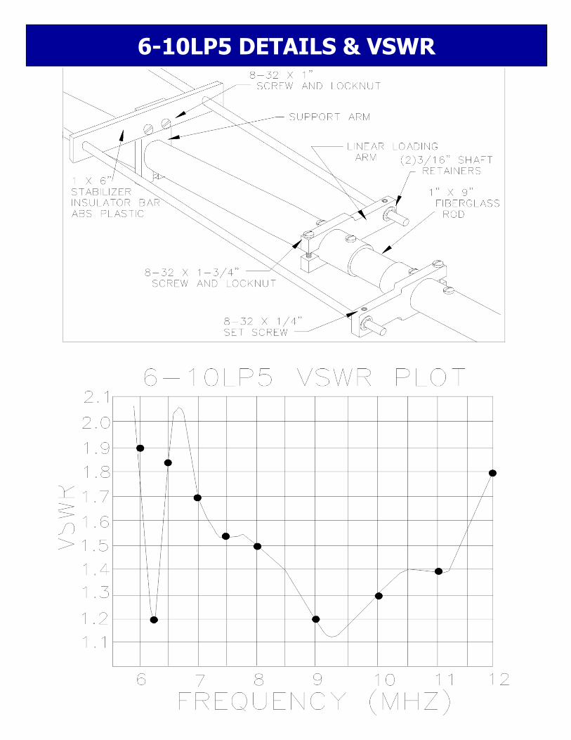
Maximum VSWR ....................... 2.0:1 Input Connector ......................... SO-239, Others avl.
Power Handling ......................... 3 kW, Higher avl. Boom Length / Dia ..................... 29.5’ / 3.0 x .125 Wall Maximum Element Length ......... 55’ Turning Radius: ......................... 32’ Mast Size ................................... 2” to 3 ” Nom. Wind area / Survival .................. 13 Sq. Ft. / 100 MPH Weight / Ship Wt. ....................... 150 Lbs. / 198 Lbs.
M2 Antenna Systems, Inc. Model No: 6-10LP5
FEATURES: The 6-10LP5 log periodic is a rugged, versatile performer designed for years of trouble free service. For the ama-teur radio operator it covers the 7 and 10 MHz amateur bands with high efficiency and no traps! Machined aluminum ele-ment-to-boom clamps and solid fiberglass rod center insulators are just a few of the unique structural features in this re-markable antenna. Linear loading of the two longest elements reduces element length and turning radius, putting less demand on the rotator and tower structure. Larger element sections are sleeved for additional strength. For continuous extended coverage, the 6-10LP5 is designed to team up with our popular 10-30LP8 log periodic. This combination efficiently and economically covers a frequency range of 6 to 30 MHz, keeping you competitive on every frequency on every band instantaneously. The 6-10LP5 is proving valuable in a variety of Maritime, Govern-ment, Commercial, MARS, Scientific and Amateur applications. Installed at 65 feet or higher, this five element antenna is a world wide performer. Solid electrical and structural design will maintain communications when other antennas have long since faded into the noise.
SPECIFICATIONS:
*Subtract 2.14 from dBi for dBd
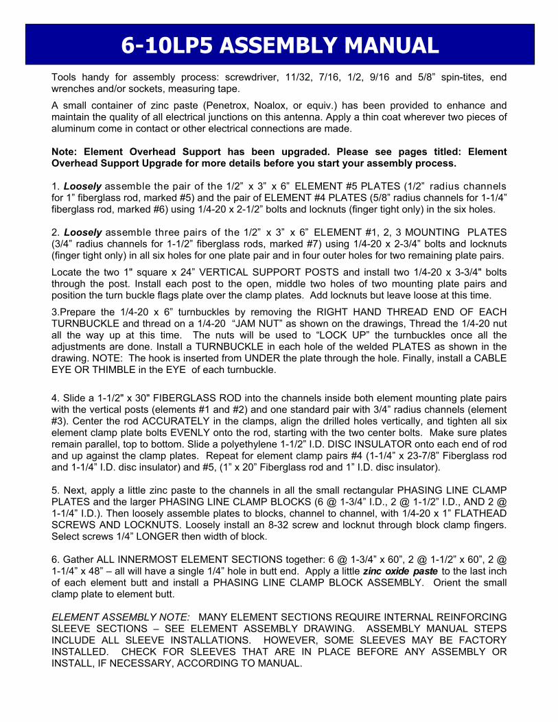
Tools handy for assembly process: screwdriver, 11/32, 7/16, 1/2, 9/16 and 5/8” spin-tites, end wrenches and/or sockets, measuring tape.
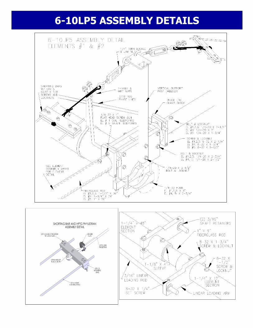
A small container of zinc paste (Penetrox, Noalox, or equiv.) has been provided to enhance and maintain the quality of all electrical junctions on this antenna. Apply a thin coat wherever two pieces of aluminum come in contact or other electrical connections are made. Note: Element Overhead Support has been upgraded. Please see pages titled: Element Overhead Support Upgrade for more details before you start your assembly process. 1. Loosely assemble the pair of the 1/2” x 3” x 6” ELEMENT #5 PLATES (1/2” radius channels for 1” fiberglass rod, marked #5) and the pair of ELEMENT #4 PLATES (5/8” radius channels for 1-1/4” fiberglass rod, marked #6) using 1/4-20 x 2-1/2” bolts and locknuts (finger tight only) in the six holes. 2. Loosely assemble three pairs of the 1/2” x 3” x 6” ELEMENT #1, 2, 3 MOUNTING PLATES (3/4” radius channels for 1-1/2” fiberglass rods, marked #7) using 1/4-20 x 2-3/4” bolts and locknuts (finger tight only) in all six holes for one plate pair and in four outer holes for two remaining plate pairs.
Locate the two 1" square x 24” VERTICAL SUPPORT POSTS and install two 1/4-20 x 3-3/4" bolts through the post. Install each post to the open, middle two holes of two mounting plate pairs and position the turn buckle flags plate over the clamp plates. Add locknuts but leave loose at this time.
3.Prepare the 1/4-20 x 6” turnbuckles by removing the RIGHT HAND THREAD END OF EACH TURNBUCKLE and thread on a 1/4-20 “JAM NUT” as shown on the drawings, Thread the 1/4-20 nut all the way up at this time. The nuts will be used to “LOCK UP” the turnbuckles once all the adjustments are done. Install a TURNBUCKLE in each hole of the welded PLATES as shown in the drawing. NOTE: The hook is inserted from UNDER the plate through the hole. Finally, install a CABLE EYE OR THIMBLE in the EYE of each turnbuckle.
4. Slide a 1-1/2" x 30" FIBERGLASS ROD into the channels inside both element mounting plate pairs with the vertical posts (elements #1 and #2) and one standard pair with 3/4” radius channels (element #3). Center the rod ACCURATELY in the clamps, align the drilled holes vertically, and tighten all six element clamp plate bolts EVENLY onto the rod, starting with the two center bolts. Make sure plates remain parallel, top to bottom. Slide a polyethylene 1-1/2” I.D. DISC INSULATOR onto each end of rod and up against the clamp plates. Repeat for element clamp pairs #4 (1-1/4” x 23-7/8” Fiberglass rod and 1-1/4” I.D. disc insulator) and #5, (1” x 20” Fiberglass rod and 1” I.D. disc insulator). 5. Next, apply a little zinc paste to the channels in all the small rectangular PHASING LINE CLAMP PLATES and the larger PHASING LINE CLAMP BLOCKS (6 @ 1-3/4” I.D., 2 @ 1-1/2” I.D., AND 2 @ 1-1/4” I.D.). Then loosely assemble plates to blocks, channel to channel, with 1/4-20 x 1” FLATHEAD SCREWS AND LOCKNUTS. Loosely install an 8-32 screw and locknut through block clamp fingers. Select screws 1/4” LONGER then width of block. 6. Gather ALL INNERMOST ELEMENT SECTIONS together: 6 @ 1-3/4” x 60”, 2 @ 1-1/2” x 60”, 2 @ 1-1/4” x 48” – all will have a single 1/4” hole in butt end. Apply a little zinc oxide paste to the last inch of each element butt and install a PHASING LINE CLAMP BLOCK ASSEMBLY. Orient the small clamp plate to element butt. ELEMENT ASSEMBLY NOTE: MANY ELEMENT SECTIONS REQUIRE INTERNAL REINFORCING SLEEVE SECTIONS – SEE ELEMENT ASSEMBLY DRAWING. ASSEMBLY MANUAL STEPS INCLUDE ALL SLEEVE INSTALLATIONS. HOWEVER, SOME SLEEVES MAY BE FACTORY INSTALLED. CHECK FOR SLEEVES THAT ARE IN PLACE BEFORE ANY ASSEMBLY OR INSTALL, IF NECESSARY, ACCORDING TO MANUAL.
6-10LP5 ASSEMBLY MANUAL
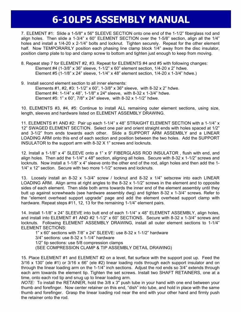
7. ELEMENT #1: Slide a 1-5/8" x 56" SLEEVE SECTION onto one end of the 1-1/2” fiberglass rod and align holes. Then slide a 1-3/4” x 60” ELEMENT SECTION over the 1-5/8” section, align all the 1/4” holes and install a 1/4-20 x 2-1/4” bolts and locknut. Tighten securely. Repeat for the other element half. Now TEMPORARILY position each phasing line clamp block 1/4” away from the disc insulator, position clamp plate to top and clamp screw to bottom and tighten just enough to keep from moving. 8. Repeat step 7 for ELEMENT #2, #3. Repeat for ELEMENTS #4 and #5 with following changes: Element #4 (1-3/8” x 36” sleeve, 1-1/2” x 60” element section, 1/4-20 x 2” hdwe. Element #5 (1-1/8” x 24” sleeve, 1-1/4” x 48” element section, 1/4-20 x 1-3/4” hdwe.) 9. Install second element section to all inner elements: Elements #1, #2, #3: 1-1/2” x 60”, 1-3/8" x 36" sleeve, with 8-32 x 2” hdwe. Element #4: 1-1/4” x 48”, 1-1/8" x 24" sleeve, with 8-32 x 1-3/4” hdwe. Element #5: 1” x 60”, 7/8" x 24" sleeve, with 8-32 x 1-1/2” hdwe. 10. ELEMENTS #3, #4, #5: Continue to install ALL remaining outer element sections, using size, length, sleeves and hardware listed on ELEMENT ASSEMBLY DRAWING. 11. ELEMENTS #1 AND #2: Pair up each 1-1/4” x 48” STRAIGHT ELEMENT SECTION with a 1-1/4” x 12” SWAGED ELEMENT SECTION. Select one pair and orient straight ends with holes spaced at 1/2” and 3-1/2” from ends towards each other. Slide a SUPPORT ARM ASSEMBLY and a LINEAR LOADING ARM onto this end of each section and position between the two holes. Add the SUPPORT INSULATOR to the support arm with 8-32 X 1” screws and locknuts. 12. Install a 1-1/8” x 4” SLEEVE onto a 1” x 9” FIBERGLASS ROD INSULATOR , flush with end, and align holes. Then add the 1-1/4" x 48" section, aligning all holes. Secure with 8-32 x 1-1/2” screws and locknuts. Now install a 1-1/8” x 4” sleeve onto the other end of the rod, align holes and then add the 1-1/4” x 12” section. Secure with two more 1-1/2” screws and locknuts. 13. Loosely install an 8-32 x 1-3/4” screw / locknut and 8-32 x 1/4” setscrew into each LINEAR LOADING ARM. Align arms at right angles to the 8-32 x 1-1/2” screws in the element and to opposite sides of each element. Then slide both arms towards the inner end of the element assembly until they butt up against screwheads (see hardware assembly dwg) and tighten 8-32 x 1-3/4” screws. Refer to the “element overhead support upgrade” page and add the element overhead support clamp with hardware. Repeat steps #11, 12, 13 for the remaining 1-1/4” element pairs. 14. Install 1-1/8” x 24” SLEEVE into butt end of each 1-1/4” x 48” ELEMENT ASSEMBLY, align holes, and install into ELEMENT #1 AND #2 1-1/2” x 60” SECTIONS. Secure with 8-32 x 1-3/4” screws and locknuts. Following ELEMENT ASSEMBLY DRAWING, install all outer element sections to 1-1/4” ELEMENT SECTIONS: 1” x 60” sections with 7/8” x 24” SLEEVE: use 8-32 x 1-1/2” hardware 3/4” sections: use 8-32 x 1-1/4” hardware 1/2” tip sections: use 5/8 compression clamps (SEE COMPRESSION CLAMP & TIP ASSEMBLY DETAIL DRAWING) 15. Place ELEMENT #1 and ELEMENT #2 on a level, flat surface with the support post up. Feed the 3/16 x 130” (ele #1) or 3/16 x 66” (ele #2) linear loading rods through each support insulator and on through the linear loading arm on the 1-1/4” inch sections. Adjust the rod ends so 3/4” extends through each arm towards the element tip. Tighten the set screws. Install two SHAFT RETAINERS, one at a time, onto each rod tip and snug up to linear loading arm. NOTE: To install the RETAINER, hold the 3/8 x 3" push tube in your hand with one end between your thumb and forefinger. Now center retainer on this end, “dish” into tube, and hold in place with the same thumb and forefinger. Grasp the linear loading rod near the end with your other hand and firmly push the retainer onto the rod.
6-10LP5 ASSEMBLY MANUAL

16. SHORTING BAR PREPARATION Locate the 8 shorting bar halves. Assemble the shorting bars with 8-32 x 7/8” screws and locknuts. Finger tighten the locknuts for now. Next, begin to assemble the phyllistrand tension lines as shown on the ELEMENT HARDWARE drawing. For element #1 use the 60” PHILLISTRND cord and for element #2 use the 124” PHILLISTRAND cord. On each shorting bar assembly, insert one end of each length of PHILLISTRAN HPTG-1200 CORD into the CENTER hole of the shorting bar. Loop the cord around the delrin strain relief and back through the other hole and allow about 2” to protrude. Place a cable clip here as a “backup” to the final clamping action of the shorting bar halves. Don’t tighten the hardware at this time. (OPTIONAL) On each phyllistrand tension line insert two more 1/8” cable clips and allow them to slide all the way to the shorting bar for now. 17. SHORTING BAR INSTALLATION Next, feed each shorting bar onto the pair of linear rod ends and position them at the measurement as shown on the DIMENSION SHEET. NOTE the dimension is measured from the OUTSIDE edge of the LL arm to the OUTSIDE edge of the shorting bar. (USING A BLACK PERMANENT MARKING PEN OR EQUIVALENT, MARK THE SPOT ON THE ROD WHERE THE SHORTING BAR SHOULD BE) Be sure the linear loading lines are centered about the main element. Once the shorting bars have been correctly set, tighten all of the 8-32 hardware. Cut off the excess material so that about 1” of rod extends beyond the shorting bar. Start a SHAFT RETAINER onto each rod tip. Push the retainers up against the shorting bar. Repeat for of the other element halves. 18. SUSPENSION OF PHYLLISTRAND TENSION LINES At this point you might want to perform the remaining steps with a friend. On a flat surface, support the ends of each element tip up so that it is at the same height as the center section. Next insert the phyllistrand tension lines through element support clamp, note the self locking phyllistrand rout through the holes, and pull tight. Rout the other end of the upper support cable through upper turnbuckles, around each thimble eye, and then finally back through the two cable clips. See the ELEMENT HARDWARE drawing for an illustration. Now pull on the free end of the phyllistrand until the entire element appears to be level. (IT MAY BE HELPFUL TO RAISE THE OUTER END OF THE ELEMENT HALF WITH A 4” BLOCK OF WOOD OR BRICK. At this point, secure the tension line by tightening the two 1/8” cable clips. After the element is straight equalize the tension of the linear loading phyllistrand support lines. Repeat this procedure for all the other element halves. The final tensioning of element support and linear loading rods is done with the TURNBUCKLES. This can be performed after the elements have been secured to the boom. Boom Assembly 19. Examine the 2-1/2” x 12’ BOOM SPLICE for nicks or bumps and file off if found. Examine the drilled boom ends to be coupled, for dings, internal burrs or chips and remove if found. Lubricate the splice bushings with light oil and slide the splice halfway into one 3” x 15’ BOOM SECTION. Align holes, and secure with 1/4-20 x 3-1/2” bolts and locknuts, but DO NOT TIGHTEN YET. Add the remaining boom section to the splice, align holes, and install bolts. Now tighten ALL the bolts. Install the 3/8” EYEBOLTS into the boom, one 3’ in from each boom end. Secure with 3/8” stainless nuts and lockwashers. 20. Loosely install two saddle clamps to the bottom of ELEMENT #1 clamp plates with 1/4-20 x 3” bolts. Slide the element onto EITHER end of the boom (its symmetrical) and position the rear clamp plate at 1” from boom end. Align boom so eyebolts are “up” and perpendicular to elements, then tighten 3” saddle clamp bolts. Position remaining elements on the boom as shown on DIMENSION SHEET. Add saddles and bolts (El’s #1, 2, 3, = 1/4-20 x 3” hdwe. / El’s #4, 5 = 1/4-20 x 2-3/4” hdwe.), align elements to #1, and tighten bolts. Dimension Sheet element spacing dimensions are center to center, but can also be used edge to edge with a tape measure.
6-10LP5 ASSEMBLY MANUAL

21. INSTALLING PHASING LINES: SEE DIMENSION SHEET & HARDWARE ASSEMBLY DRAWINGS A. Start with the shortest set between element #4 and #5 For each set, feed the phasing lines through a 3/4” x 3” DELRIN SPACER so that the spacer sits at the crossover point between the lines. Hold the spacer in place loosely around the boom with a large nylon tie but don't tighten it yet. Adjust phasing lines so that their bends are even and the lines run parallel to the boom.
B. Apply a small amount of conductive paste to the rod ends and feed the #5 ends into the clamp block channels until 1/4” extends beyond clamp. Temporarily tighten the 1/4-20 x 1” flathead screws and locknuts on element #5. Insert the other rod ends into the clamp block assemblies on element #4 but do not tighten. Continue to the next phasing line set between element #4 and #3 Apply paste and insert the ends into the clamp blocks at element #4 and NOW tighten the flathead screws and nylon tie. Then adjust the block assemblies flush to the disc insulators and tighten 8-32 clamp screws.
C. Continue in the same fashion tightening the hardware and nylon ties as you go.
D. Before securing phasing lines on ELEMENT #1, attach the 20 turn COIL to screw studs, and add 1/4” flat washers and locknuts and tighten. 22. MOUNTING THE 4:1 BROAD BAND BALUN: Secure the BALUN to the 2" x 4-1/2" BALUN MOUNTING PLATE with a 2-1/2" U-bolt and cradle. DO NOT OVERTIGHTEN - BALUN HOUSING COULD BE DAMAGED! Install assembly to boom with 3" U-bolt and cradle. Position balun just to the rear of element #5, connector pointing to forwards and leads easily reaching clamp block screw studs. Now remove the 1/4” locknuts from the clamp block screws. Apply some zinc paste to the lugs on the balun leads and place over each screw stud. Add 1/4” flat washers and locknuts and retighten. Adjust the block assemblies flush to the disc insulators and tighten 8-32 clamp screws. If practical at this time, attach the main 50 Ohm feed line to the balun, loop back under boom, and route down to the boom to mast plate position (at phasing line crossover point between Elements #2 and #3). Secure the coax with the large nylon ties. 23. Mount the BOOM TO MAST PLATE using 3” U-bolts, 3/8-16 stainless lockwashers, and nuts. Center the plate at the crossover point of the phasing lines between element #2 and #3. Align plate to vertical and tighten nuts. Shape the phasing lines as needed to clear the plate by at least 1/2”. Four heavy duty 2” U-bolts are provided for mounting antenna to mast. 24. Do a final element alignment if necessary and check over the entire antenna for loose hardware. Check that phasing rods are straight and parallel. Tighten the nylon ties securing the Delrin spacers.
6-10LP5 ASSEMBLY MANUAL

6-10LP5 ASSEMBLY MANUAL 25. OVERHEAD BOOM SUPPORT SYSTEM. A. Attach one end of the 5/16" Dacron cord to the rear eyebolt using two turns around the eyebolt and a series of three half hitches or equivalent knots. Without cutting the cord, secure other end at the front eyebolt. Pull on the knots HARD to SET them and tape the excess cord back to main cord tightly with black vinyl electricians tape. Seal ends with heat or flame to prevent fraying.
B. TEMPORARILY insert a standard 2” U-bolt through the turnbuckle plate and add two nuts so about 1/2 inch of the threads stick out. Insert U-bolt studs through the top set of 2” U-bolt holes in the boom to mast plate from the boom side and add two more nuts. Open the two turnbuckles up until just a thread or two from each end shows inside the body of the turnbuckle. Hook the turnbuckles into the holes at the edge of the turnbuckle plate. Equalize the Dacron cord over the plate and cut it. Take two wraps of the cord through the eye of the rear turnbuckle, PULL the cord as tight as possible and make the knots as before. Repeat for the front cord section and turnbuckle. Cut off any excess over one foot long and again seal and tape the excess cord back to the main cord. C. Now DISASSEMBLE the U-bolt from the boom to mast plate. The guy assembly is now centered and the turnbuckle plate ready to be installed to the mast and raised until the boom is straight. D. If practical, after the final assembly and before installation, let the overhead guy system support the boom and take a set overnight: Install a 2’ to 3’ temporary 2” mast section to the boom to mast plate and attach and raise the turnbuckle plate. Support the antenna at the boom to mast plate. The Dacron cord DOES NOT STRETCH UNDER LOAD but cord and knots will take a SET and the boom may droop just a bit. Reset turnbuckle plate. If your boom droops again following this adjustment, check your knots - they may be may be slipping. If an overnight set is not possible, then after installing antenna on mast, lean or pull on the cords to increase the tension and help the knots take their final “set.” Make sure the knots are not slipping. When the guy system has taken a “set”, loosen the 2” U-bolt and adjust turnbuckle plate height until boom is straight and level.
E. After final installation, do any minor boom straightening with the turnbuckles. Then safety wire to prevent changes to settings. 26. This completes the ASSEMBLY. When the antenna is installed in position on the mast, the main feedline can be attached and sealed at that time. REMEMBER to support the feedline at the antenna boom and on the mast. Leave an adequate feedline loop for rotation around the tower. Mount horizontally polarized VHF and UHF antennas at least 40” above or below this antenna to minimize interaction.
Carefully designed and manufactured by:
M2 ANTENNA SYSTEMS, INC. 4402 N. Selland Ave.
Fresno, CA 93711 (559) 432-8873 Fax: 432-3059
www.m2inc.com Email: [email protected]

6-10LP5 ELEMENT LAYOUTS

6-10LP5 DIMENSION SHEET

2M4 ASSEMBLY MANUAL ELEMENT OVERHEAD SUPPORT UPGRADE
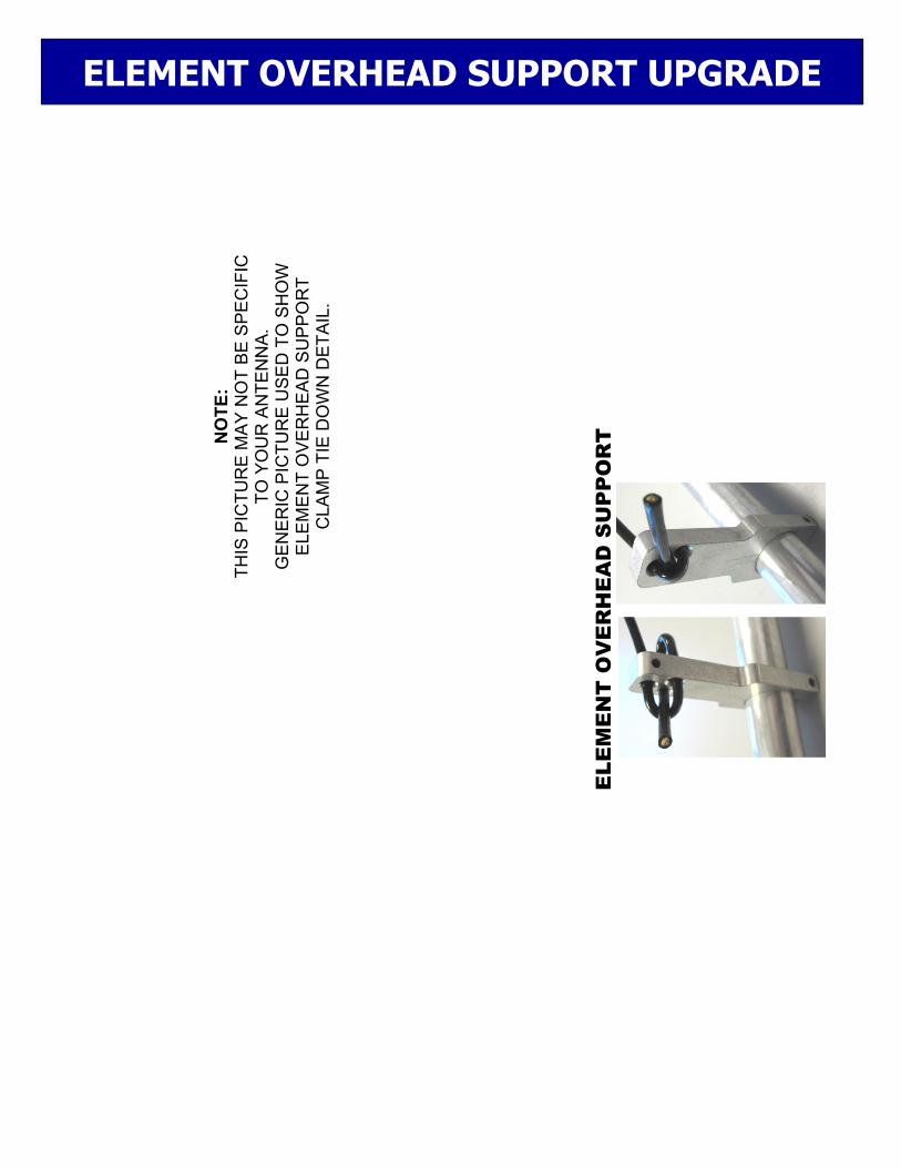
ELEMENT OVERHEAD SUPPORT UPGRADE
NO
TE
: T
HIS
PIC
TU
RE
MA
Y N
OT
BE
SP
EC
IFIC
T
O Y
OU
R A
NT
EN
NA
. G
EN
ER
IC P
ICT
UR
E U
SE
D T
O S
HO
W
ELE
ME
NT
OV
ER
HE
AD
SU
PP
OR
T
CLA
MP
TIE
DO
WN
DE
TA
IL.
ELE
ME
NT
OV
ER
HE
AD
SU
PP
OR
T
6-10LP5 ASSEMBLY DETAILS
6-10LP5 DETAILS & VSWR

GENERIC COMPRESSION CLAMP DETAIL

DESCRIPTION ......................................................................... QTY Boom Section, 3 x .125 x 180" ............................................................ 2 Boom Splice 2-1/2 x .125 x 144" (ASSEMBLED) ............................... 1 Boom to Mast Plate 8 x 8 x 1/4" plate alum. ....................................... 1 Inner Element Section 1-3/4x.058x60" SOE, 1/4" hole ....................... 6 Inner Element Section 1-1/2x.058x60" SOE, 1/4" hole ...................... 2 Inner Element Section 1-1/4x.058x48" SOE, 1/4" hole ....................... 2 Element Section 1-1/2x.058x60" SOE, ............................................... 6 Element Section 1-1/4x.058x48" SOE, .............................................. 4 Element Section 1-1/4x.058x48" STR ................................................ 4 Element Section 1-1/4x,058x12" SOE ................................................ 4 Element Section 1.0x.058x60"SOE .................................................. 10 Element Section 0.75x.049x48" SOE ............................................... 10 Tip Element Section 0.5x.049x52" STR .............................................. 6 Tip Element Section 0.5x.049x48" STR .............................................. 2 Tip Element Section 0.5x.049x50" STR .............................................. 2 Butt Element Sleeve 1-5/8x.058x56", 1/4” hole .................................. 6 Element Sleeve 1-3/8x.058x36" .......................................................... 8 Element Sleeve 1-1/8x.058x24" .......................................................... 8 Butt Element Sleeve 1-1/8 x .058 x 24”, 1/4” hole .............................. 2 Element Sleeve, linear loading, 1-1/8 x .058 x 4” ............................... 8 Element Sleeve 7/8x.058x24" ........................................................... 10 Element Mounting Plates 1/2x3.0x6” .625 Rad #6 .............................. 2 Element Mounting Plates 1/2x3.0x6” .50 Rad. #5 ............................... 2 Element Mounting Plates 1/2x3.0x6” .750 Rad. #7 ............................. 6 Saddle, Element Mounting Plate ...................................................... 10 Element Clamp Block for 1-3/4" tubes ................................................ 6 Element Clamp Block for 1-1/2" tubes ................................................ 2 Element Clamp Block for 1-1/4" tubes ................................................ 2 Small Clamp Block ........................................................................... 10 Linear Loading Arm 0.375x1.5x3.75 FOR 1-1/4 tube ......................... 8 Turn Buckle, 1/4” H&E ........................................................................ 4 Cable Eye, 1/8 .................................................................................... 4 Wire Nut, 1/8 ..................................................................................... 16 Phylistrand cable, HPTG 1200 x 60” .................................................. 2 Phylistrand cable, HPTG 1200 x 124” ................................................ 2 Strain Relief, 1/2 x 1/2 Delrin .............................................................. 4 Shorting Bars 1/4 x 3/4 x 5.875 alum. Bar (M2ASB0250) ................... 8 Spacers, phasing line, 3/4” x 3” .......................................................... 4 Dacron Rope 5/16 x 28ft. .................................................................... 1 Rod, 1-1/2x30", Fiberglass ................................................................. 3
6-10LP5 PARTS & HARDWARE

Rod, 1-1/4x24", Fiberglass ................................................................. 1 Rod, 1"x24", Fiberglass ...................................................................... 1 Rod, Linear loading, 1”x9", Fiberglass ............................................... 4 Balun, 4:1, 3 KW ................................................................................ 1 Balun Mounting Plate, 2 x .125 x 4-1/2” ............................................ 1 Coil, #10 AWG 20T on 3/4 form ........................................................ 1 Phasing rods, 3/16 x (pre-cut and pre-bent) ...................................... 8 Linear loading Rod 3/16" x 130" ......................................................... 4 Linear Loading Rod 3/16" x 66" ......................................................... 4 Disc Insulator, Polyethylene, 1-1/2" ................................................... 6 Disc Insulator, Polyethylene, 1-1/4" ................................................... 2 Disc Insulator, Polyethylene, 1" .......................................................... 2 Insulator, Stabilizer bar, non-metallic 1 x 6 ........................................ 4 Support Arm, for Insulator stabilizer bar, 1-1/4” hole .......................... 4 5/8” Compression Clamp ................................................................. 10 U-Bolt, 3" with cradle .......................................................................... 3 U-bolt, 2-1/2 with cradle ..................................................................... 1 U-Bolt, 2" Heavy Duty, with cradle ..................................................... 4 U-bolts, 2” standard ........................................................................... 1 Eyebolts 3/8" x 6” ............................................................................... 2 Turnbuckles 3/8" ................................................................................ 2 Turnbuckle plate, 2 x 4 x 1/4" alum. ................................................... 1 ELEMENT OVERHEAD SUPPORT UPGRADE ..................... QTY Support Post, LL, 1” X 1” X 24” W/SLOT (M2AVR0051) .................... 2 Element Overhead Support Clamp .................................................... 4 Element Overhead Support Line, HPTG1200 x 34’ ........................... 2 Turnbuckle, 1/4 X 5-1/4”, Hook and Eye ............................................ 4 Cable Eye, 6/16” ................................................................................ 4 Wire Clip, 1/8” .................................................................................... 8 Bolt, 1/4-20 x 3-3/4” ........................................................................... 4 Locknut, 1/4-20,ss .............................................................................. 4 Nut, 1/4-20,ss ..................................................................................... 4 Screw, 8-32 x 1-1/2”, Pan Head Phil,ss ............................................. 4 Locknut, 8-32,ss ................................................................................. 4
6-10LP5 PARTS & HARDWARE

HARDWARE BAG ................................................................... QTY Bolt, 1/4-20 x 3-1/2" hex cap stainless ............................................... 8 Bolt, 1/4-20 x 3" ............................................................................... 12 Bolt, 1/4-20 x 2-3/4" ......................................................................... 22 Bolt, 1/4-20 x 2-1/2" ......................................................................... 12 Bolt, 1/4-20 x 2-1/4" ........................................................................... 6 Bolt, 1/4-20x2" ................................................................................... 2 Bolt, 1/4-20x1-3/4 ............................................................................... 2 Bolt, 1/4-20 x 1" Countersunk Flathead ........................................... 10 Nut, 1/4-20, Locking ......................................................................... 54 Nut, 1/4-20 ......................................................................................... 4 Flat Washer, 1/4 ................................................................................. 4 Screw, 8-32x2-1/4" ............................................................................. 6 Screw, 8-32x2" ................................................................................. 12 Screw, 8-32x1-3/4" ........................................................................... 30 Screw, 8-32x1-1/2" ........................................................................... 38 Screw, 8-32x1-1/4" ........................................................................... 20 Screw, 8-32x1" ................................................................................... 8 Screw, 8-32 x 7/8 ............................................................................. 20 Screw, 8-32 x 1/2 ............................................................................. 10 Set Screw, 8-32 x 1/4" ..................................................................... 16 Nut, 8-32, SS ................................................................................... 10 Nut, 8-32, Locking .......................................................................... 136 Nut, 5/16-18, stainless ....................................................................... 4 Lockwasher, 5/16" split ring stainless ................................................ 4 Nut, 3/8-16 stainless ........................................................................ 18 Lockwasher, 3/8", split ring stainless ............................................... 18 Shaft Retainers, 3/16 ....................................................................... 22 Nylon ties, large 11" black .................................................................. 8 Push tube for keepers, 3/8 x 3" alum ................................................. 1 Allen wrench, 5/32 ............................................................................. 1 Noalox ................................................................................................ 1
Carefully designed and manufactured by:
M2 ANTENNA SYSTEMS, INC. 4402 N. Selland Ave.
Fresno, CA 93711 (559) 432-8873 Fax: 432-3059
www.m2inc.com Email: [email protected]
6-10LP5 PARTS & HARDWARE