LUBRICATION EQUIPMENT - LDI Industries EQUIPMENT ... Aluminum bowl and sight gage may be specifi ed...
72
LUBRICATION EQUIPMENT [email protected] www.ldi-industries.com Ph : 920-682-6877 Fx : 920-684-7210 Pg LE-1 Dimensions and specifications are subject to change without notice. Not all items are Made-To-Stock, contact us for availability. 02/14 TABLE OF CONTENTS AIR OVER OIL RESERVOIRS Base Mount ...................................................... LE-2 Wall Mount ....................................................... LE-3 CENTRALIZED LUBRICATION SYSTEMS Grease Cartridge Adapter ................................... LE-4 Grease Reservoirs - Remote/Wall Mount ............... LE-5 PMP100 Series - Pneumatic................................. LE-6 PMP200 Series - Electric ..................................... LE-7 PMP300 Series - Pneumatic Panel Mount Systems .. LE-8 PMP400 Series - Electric Panel Mount Systems ...... LE-9 PMP500 Series - Pneumatic NEMA Mount Systems . LE-10 PMP600 Series - Electric NEMA Mount Systems ...... LE-11 Repeat Cycle Timer ............................................ LE-12 Solenoid Valve .................................................. LE-13 CHAIN OILERS & APPLICATORS NVB Series - Straight Valve Brush, Round or Flat ... LE-14 NVB Series - Flat Strip Brush, Straight or 45° ........ LE-15 NVB Series - 45° Valve with Flat Brush ................. LE-16 NVB Series - Rotary Wheel Valve Brush ................ LE-16 RDB300 Series .................................................. LE-17 REB Series........................................................ LE-18 Replacement Brushes ......................................... LE-19 SB Series ......................................................... LE-20 SV Series ......................................................... LE-21 FLOW SIGHTS F50/60 Series ................................................... LE-22 F150/160 Series ................................................ LE-23 F250 Series ...................................................... LE-24 F300 Series ...................................................... LE-25 F560 Series ...................................................... LE-26 INLINE FILTER - LIQUID Inline Filter - Liquid ........................................... LE-27 LUBRICATORS & DISPENSERS GUN-fil ® Lubricator ............................................ LE-28 R100 Series ...................................................... LE-29 RCL Series ........................................................ LE-32 RDF Series Pipe Thread NPTF .............................. LE-33 RDF Series Straight Thread/Remote Mount............ LE-34 RDM Series ....................................................... LE-35 REF Series ........................................................ LE-36 REM Series ....................................................... LE-37 REO Series ....................................................... LE-38 RFF100 Series ................................................... LE-39 RVP Series........................................................ LE-40 METERING & SHUT OFF VALVES ESS Series........................................................ LE-41 ESV Series........................................................ LE-42 FFG Series - Heavy Duty .................................... LE-43 Mini Line Series ................................................. LE-44 N100 Series ...................................................... LE-46 N400 Series ...................................................... LE-47 N470 Series ...................................................... LE-48 NVM Series ....................................................... LE-49 TMF Series ....................................................... LE-50 PRESSURE/VACUUM RELIEF VENTS PRV100 Series .................................................. LE-51 PRV200 Series .................................................. LE-51 SAMPLING VALVE V101 Series ...................................................... LE-52 VENTED OIL GAGES G100 Series...................................................... LE-53 GT100 Series .................................................... LE-54 GTW100 Series ................................................. LE-55 G150 Series...................................................... LE-56 GTW150 Series ................................................. LE-57 G200 Series...................................................... LE-58 G260 Series...................................................... LE-59 G300 Series...................................................... LE-60 G320 Series...................................................... LE-61 G400 Series...................................................... LE-62 G420 Series...................................................... LE-63 G650 Series...................................................... LE-64 G710 Series...................................................... LE-65 G800 Series...................................................... LE-66 G900 Series...................................................... LE-67 VENTS & BREATHERS AV100 Series .................................................... LE-68 AV200 Series .................................................... LE-68 AV50 Series ...................................................... LE-69 FV100 Series .................................................... LE-69 APPENDICES Oil Gage Modifications ........................................ LE-A1 Installation Instructions - PMP100-() Air Operated . LE-A2 Toggle Valve Adjustment Instructions ................... LE-A3
Transcript of LUBRICATION EQUIPMENT - LDI Industries EQUIPMENT ... Aluminum bowl and sight gage may be specifi ed...

LUBRICATION EQUIPMENT
Ph : 920-682-6877Fx : 920-684-7210
Pg LE-1
Dimensions and specifi cations are subject to change without notice. Not all items are Made-To-Stock, contact us for availability. 02/14
TABLE OF CONTENTS
AIR OVER OIL RESERVOIRSBase Mount ...................................................... LE-2Wall Mount ....................................................... LE-3
CENTRALIZED LUBRICATION SYSTEMSGrease Cartridge Adapter ................................... LE-4Grease Reservoirs - Remote/Wall Mount ............... LE-5PMP100 Series - Pneumatic ................................. LE-6PMP200 Series - Electric ..................................... LE-7PMP300 Series - Pneumatic Panel Mount Systems .. LE-8PMP400 Series - Electric Panel Mount Systems ...... LE-9PMP500 Series - Pneumatic NEMA Mount Systems . LE-10PMP600 Series - Electric NEMA Mount Systems ...... LE-11Repeat Cycle Timer ............................................ LE-12Solenoid Valve .................................................. LE-13
CHAIN OILERS & APPLICATORSNVB Series - Straight Valve Brush, Round or Flat ... LE-14NVB Series - Flat Strip Brush, Straight or 45° ........ LE-15NVB Series - 45° Valve with Flat Brush ................. LE-16NVB Series - Rotary Wheel Valve Brush ................ LE-16RDB300 Series .................................................. LE-17REB Series........................................................ LE-18Replacement Brushes ......................................... LE-19SB Series ......................................................... LE-20SV Series ......................................................... LE-21
FLOW SIGHTSF50/60 Series ................................................... LE-22F150/160 Series ................................................ LE-23F250 Series ...................................................... LE-24F300 Series ...................................................... LE-25F560 Series ...................................................... LE-26
INLINE FILTER - LIQUIDInline Filter - Liquid ........................................... LE-27
LUBRICATORS & DISPENSERSGUN-fi l® Lubricator ............................................ LE-28R100 Series ...................................................... LE-29RCL Series ........................................................ LE-32RDF Series Pipe Thread NPTF .............................. LE-33RDF Series Straight Thread/Remote Mount ............ LE-34RDM Series ....................................................... LE-35REF Series ........................................................ LE-36REM Series ....................................................... LE-37REO Series ....................................................... LE-38RFF100 Series ................................................... LE-39RVP Series ........................................................ LE-40
METERING & SHUT OFF VALVESESS Series ........................................................ LE-41ESV Series ........................................................ LE-42FFG Series - Heavy Duty .................................... LE-43Mini Line Series ................................................. LE-44N100 Series ...................................................... LE-46N400 Series ...................................................... LE-47N470 Series ...................................................... LE-48NVM Series ....................................................... LE-49TMF Series ....................................................... LE-50
PRESSURE/VACUUM RELIEF VENTSPRV100 Series .................................................. LE-51PRV200 Series .................................................. LE-51
SAMPLING VALVEV101 Series ...................................................... LE-52
VENTED OIL GAGESG100 Series ...................................................... LE-53GT100 Series .................................................... LE-54GTW100 Series ................................................. LE-55G150 Series ...................................................... LE-56GTW150 Series ................................................. LE-57G200 Series ...................................................... LE-58G260 Series ...................................................... LE-59G300 Series ...................................................... LE-60G320 Series ...................................................... LE-61G400 Series ...................................................... LE-62G420 Series ...................................................... LE-63G650 Series ...................................................... LE-64G710 Series ...................................................... LE-65G800 Series ...................................................... LE-66G900 Series ...................................................... LE-67
VENTS & BREATHERSAV100 Series .................................................... LE-68AV200 Series .................................................... LE-68AV50 Series ...................................................... LE-69FV100 Series .................................................... LE-69
APPENDICESOil Gage Modifi cations ........................................ LE-A1Installation Instructions - PMP100-() Air Operated . LE-A2Toggle Valve Adjustment Instructions ................... LE-A3
JG
C
B
F
D-NPTF-AIR INLETFILLER
H
A-DIA
1/4 NPTFEQUALIZER
1/4-20UNF .50 [12.70]DEEP FOR MOUNTING (2)
OUTLETFLUIDE-NPTF
Air Over Oil Reservoir - Base Mount
Part Number
Capacityinches3
(cm3)
Dimensional Informationinches(mm)
PolymerAluminumw/gage Polymer Aluminum A B C D E F G H J
A/OR1009-1 — 6.90(113.10)
8.80(144.20)
2.50(63.50)
4.12(104.60)
2.25(57.20) 1/8 1/4 1.44
(36.60).81
(20.60).25
(6.40)1.25
(31.80)
A/OR1018-2 A/OR11018-2 14.00(229.40)
18.00(295.00)
2.50(63.50)
6.62(168.10)
4.75(120.60) 1/4 1/4 1.44
(36.60).81
(20.60).25
(6.40)1.25
(31.80)
A/OR1024-2 — 20.00(327.70)
26.00(426.10)
2.50(63.50)
8.62(218.90)
6.75(171.40) 1/4 1/4 1.44
(36.60).81
(20.60).25
(6.40)1.25
(31.80)
A/OR1030-2 A/OR11030-2 26.00(426.10)
33.00(540.80)
2.50(63.50)
10.62(269.70)
8.75(222.20) 1/4 1/4 1.44
(36.60).81
(20.60).25
(6.40)1.25
(31.80)
A/OR1042-2 — 35.00(573.40)
45.00(737.40)
2.50(63.50)
13.62(345.90)
11.75(298.40) 1/4 1/4 1.44
(36.60).81
(20.60).25
(6.40)1.25
(31.80)
A/OR2053-3 A/OR12053-3 47.00(770.20)
56.00(917.70)
3.50(88.90)
8.94(227.10)
6.88(174.8) 1/4 3/8 1.62
(41.10).94
(23.90).50
(12.70)2.00
(50.80)A/OR2075-3
— 67.00(1098.00)
79.00(1295.00)
3.50(88.90)
11.81(300.00)
9.75(247.60) 1/4
3/8 1.62(41.10)
.94(23.90)
.50(12.70)
2.00(50.80)A/OR2075-4 1/2
A/OR2100-3 — 88.00(1442.00)
104.00(1704.00)
3.50(88.90)
15.08(383.00)
12.75(323.80) 1/4 3/8 1.62
(41.10).94
(23.90).50
(12.70)2.00
(50.80)
A/OR2150-3 — 130.00(2130.00)
153.00(2507.00)
3.50(88.90)
20.81(528.60)
18.75(476.20) 1/4 3/8 1.62
(41.10).94
(23.90).50
(12.70)2.00
(50.80)
A/OR2200-3 — 171.00(2802.00)
201.00(3294.00)
3.50(88.90)
27.02(686.30)
24.75(628.60) 1/4 3/8 1.62
(41.10).94
(23.90).50
(12.70)2.00
(50.80)
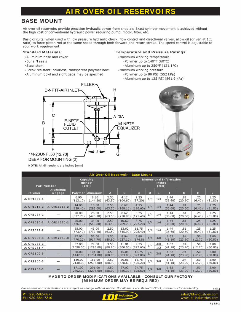
AIR OVER OIL RESERVOIRSBASE MOUNTAir over oil reservoirs provide precision hydraulic power from shop air. Exact cylinder movement is achieved without the high cost of conventional hydraulic power requiring pump, motor, fi lter, etc.
Basic circuits, when used with low pressure hydraulic check, fl ow control and directional valves, allow oil (driven at 1:1 ratio) to force piston rod at the same speed through both forward and return stroke. The speed control is adjustable to your work requirement.
Standard Materials: ▪Aluminum base and cover ▪Buna N seals ▪Steel stem ▪Break resistant, colorless, transparent polymer bowl ▪Aluminum bowl and sight gage may be specified
Temperature and Pressure Ratings: ▪Maximum working temperature
▫Polymer up to 140°F (60°C) ▫Aluminum up to 250°F (121.1°C)
▪Maximum working pressure ▫Polymer up to 80 PSI (552 kPa) ▫Aluminum up to 125 PSI (861.9 kPa)
MADE TO ORDER MODIFICATIONS AVAILABLE - CONSULT OUR FACTORY(MINIMUM ORDER MAY BE REQUIRED)
Ph : 920-682-6877Fx : 920-684-7210
Pg LE-2
Dimensions and specifi cations are subject to change without notice. Not all items are Made-To-Stock, contact us for availability. 02/14
NOTE: All dimensions are inches [mm]
Air Over Oil Reservoir - Wall Mount
Part No.
Capacityinches3
(cm3) Ainches(mm)
Binches(mm)Polymer
Alumuniumw/gage Polymer Alum.
A/OR5075-3 — 97.00(1589.50)
102.0(1671.50)
7.06(179.32)
4.56(115.82)
A/OR5100-3 — 127.00(2081.20)
133.00(2179.50)
8.56(217.42)
6.06(153.92)
— A/OR15175-3 196.00(3211.90)
205.00(3359.30)
12.06(306.32)
9.56(242.82)
A/OR5200-3 — 220.0(3605.2)
231.0(3785.4)
13.31(388.07)
10.81(274.57)
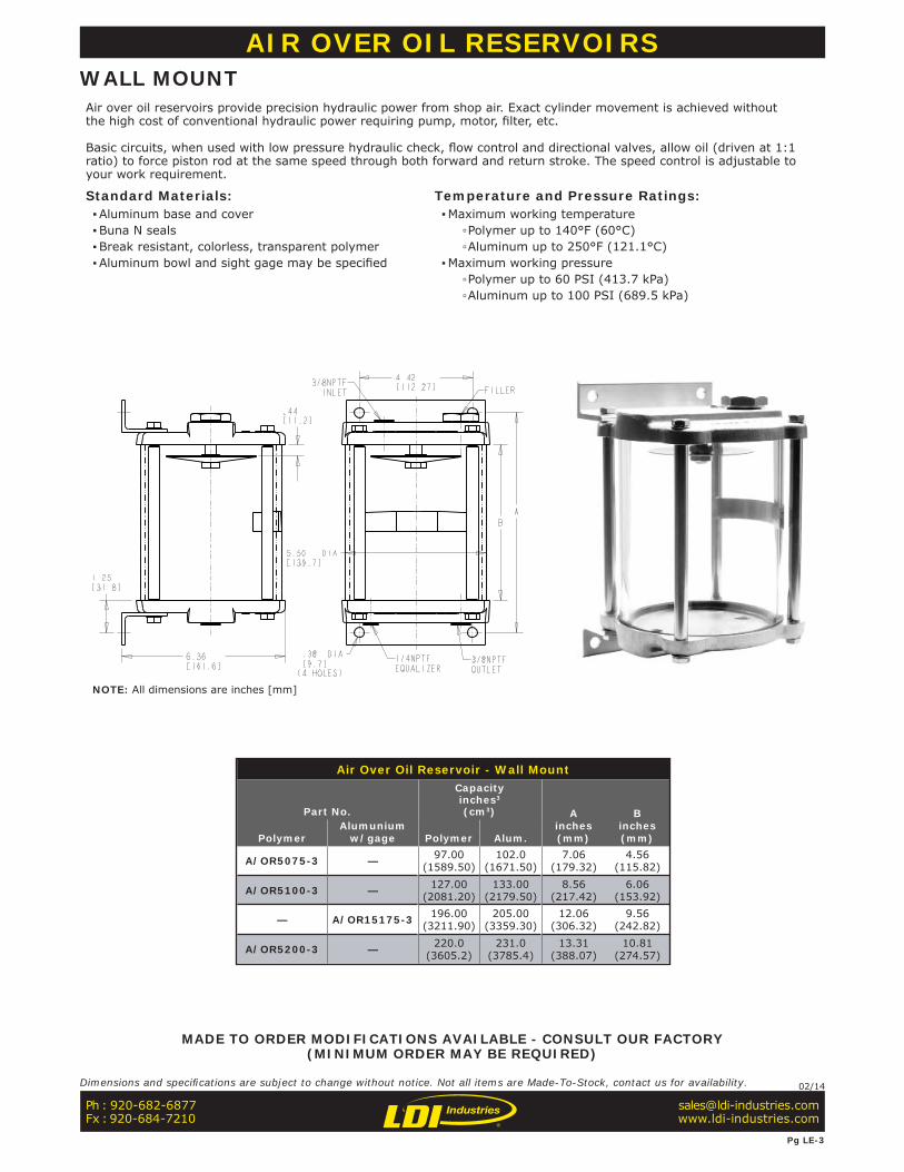
AIR OVER OIL RESERVOIRSWALL MOUNTAir over oil reservoirs provide precision hydraulic power from shop air. Exact cylinder movement is achieved without the high cost of conventional hydraulic power requiring pump, motor, fi lter, etc.
Basic circuits, when used with low pressure hydraulic check, fl ow control and directional valves, allow oil (driven at 1:1 ratio) to force piston rod at the same speed through both forward and return stroke. The speed control is adjustable to your work requirement.
Standard Materials: ▪Aluminum base and cover ▪Buna N seals ▪Break resistant, colorless, transparent polymer ▪Aluminum bowl and sight gage may be specifi ed
Temperature and Pressure Ratings: ▪Maximum working temperature
▫Polymer up to 140°F (60°C) ▫Aluminum up to 250°F (121.1°C)
▪Maximum working pressure ▫Polymer up to 60 PSI (413.7 kPa) ▫Aluminum up to 100 PSI (689.5 kPa)
MADE TO ORDER MODIFICATIONS AVAILABLE - CONSULT OUR FACTORY(MINIMUM ORDER MAY BE REQUIRED)
Ph : 920-682-6877Fx : 920-684-7210
Pg LE-3
Dimensions and specifi cations are subject to change without notice. Not all items are Made-To-Stock, contact us for availability. 02/14
NOTE: All dimensions are inches [mm]
Grease Cartridge Adapters
Part No.
AInches(mm)
BInches(mm)
COutlet
CapacityNominal
Cartridge Weight
GCA100 1.75(44.45)
2.75(69.85) 1/4-18NPTF 3 oz.
(85g)
GCA200 2.50(63.50)
2.81(71.37) 1/4-18NPTF 14 oz.
(397g)
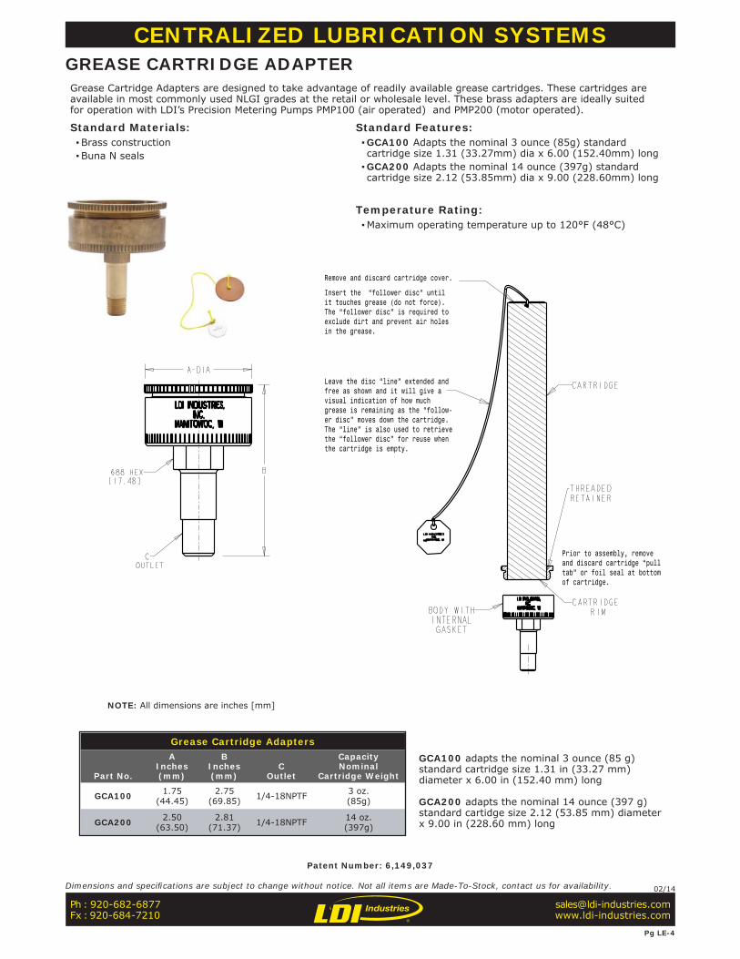
Remove and discard cartridge cover.
Insert the “follower disc” until it touches grease (do not force). The “follower disc” is required to exclude dirt and prevent air holes in the grease.
Leave the disc “line” extended and free as shown and it will give a visual indication of how much grease is remaining as the “follow-er disc” moves down the cartridge. The “line” is also used to retrieve the “follower disc” for reuse when the cartridge is empty.
Prior to assembly, remove and discard cartridge “pull tab” or foil seal at bottom of cartridge.
CENTRALIZED LUBRICATION SYSTEMSGREASE CARTRIDGE ADAPTERGrease Cartridge Adapters are designed to take advantage of readily available grease cartridges. These cartridges are available in most commonly used NLGI grades at the retail or wholesale level. These brass adapters are ideally suited for operation with LDI’s Precision Metering Pumps PMP100 (air operated) and PMP200 (motor operated).
Standard Materials: ▪Brass construction ▪Buna N seals
Standard Features: ▪GCA100 Adapts the nominal 3 ounce (85g) standard cartridge size 1.31 (33.27mm) dia x 6.00 (152.40mm) long ▪GCA200 Adapts the nominal 14 ounce (397g) standard cartridge size 2.12 (53.85mm) dia x 9.00 (228.60mm) long
Temperature Rating: ▪Maximum operating temperature up to 120°F (48°C)
Patent Number: 6,149,037
GCA100 adapts the nominal 3 ounce (85 g) standard cartridge size 1.31 in (33.27 mm) diameter x 6.00 in (152.40 mm) long
GCA200 adapts the nominal 14 ounce (397 g) standard cartidge size 2.12 (53.85 mm) diameter x 9.00 in (228.60 mm) long
Ph : 920-682-6877Fx : 920-684-7210
Pg LE-4
Dimensions and specifi cations are subject to change without notice. Not all items are Made-To-Stock, contact us for availability. 02/14
NOTE: All dimensions are inches [mm]
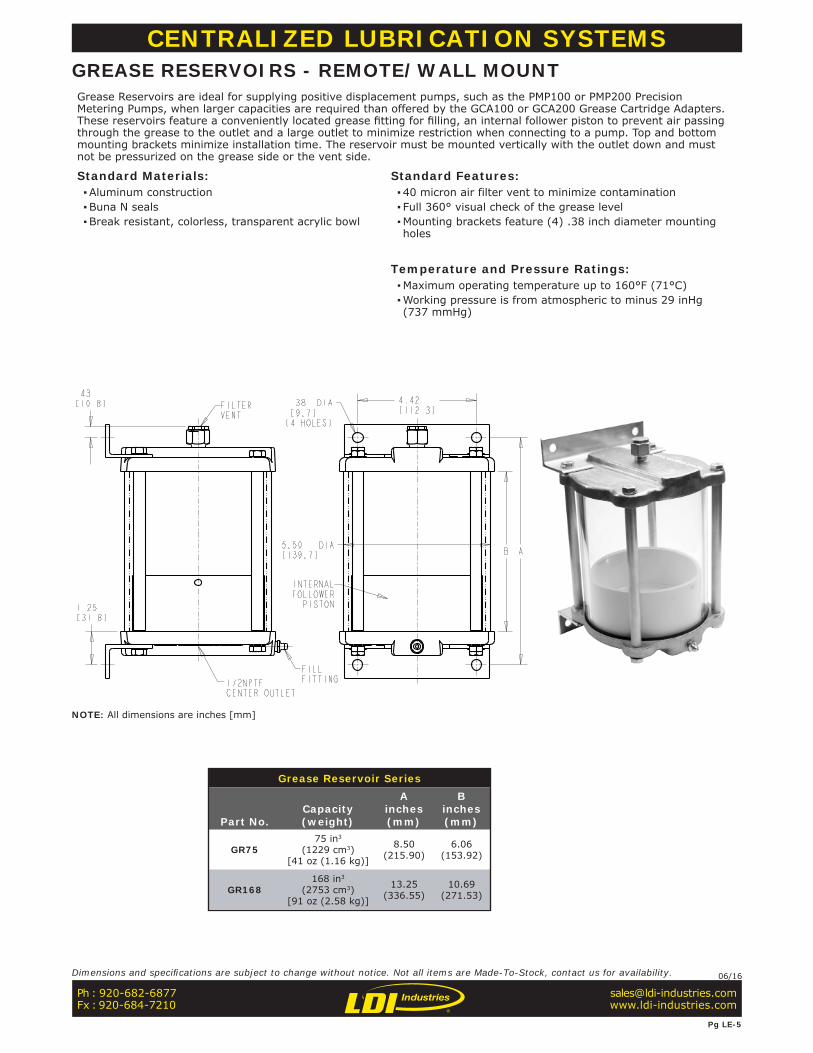
Grease Reservoir Series
Part No.Capacity(weight)
Ainches(mm)
Binches(mm)
GR7575 in3
(1229 cm3)[41 oz (1.16 kg)]
8.50(215.90)
6.06(153.92)
GR168168 in3
(2753 cm3)[91 oz (2.58 kg)]
13.25(336.55)
10.69(271.53)
CENTRALIZED LUBRICATION SYSTEMSGREASE RESERVOIRS - REMOTE/WALL MOUNTGrease Reservoirs are ideal for supplying positive displacement pumps, such as the PMP100 or PMP200 Precision Metering Pumps, when larger capacities are required than offered by the GCA100 or GCA200 Grease Cartridge Adapters. These reservoirs feature a conveniently located grease fi tting for fi lling, an internal follower piston to prevent air passing through the grease to the outlet and a large outlet to minimize restriction when connecting to a pump. Top and bottom mounting brackets minimize installation time. The reservoir must be mounted vertically with the outlet down and must not be pressurized on the grease side or the vent side.
Standard Materials: ▪Aluminum construction ▪Buna N seals ▪Break resistant, colorless, transparent acrylic bowl
Standard Features: ▪40 micron air filter vent to minimize contamination ▪ Full 360° visual check of the grease level ▪Mounting brackets feature (4) .38 inch diameter mounting holes
Temperature and Pressure Ratings: ▪Maximum operating temperature up to 160°F (71°C) ▪Working pressure is from atmospheric to minus 29 inHg (737 mmHg)
Ph : 920-682-6877Fx : 920-684-7210
Pg LE-5
Dimensions and specifi cations are subject to change without notice. Not all items are Made-To-Stock, contact us for availability. 06/16
NOTE: All dimensions are inches [mm]
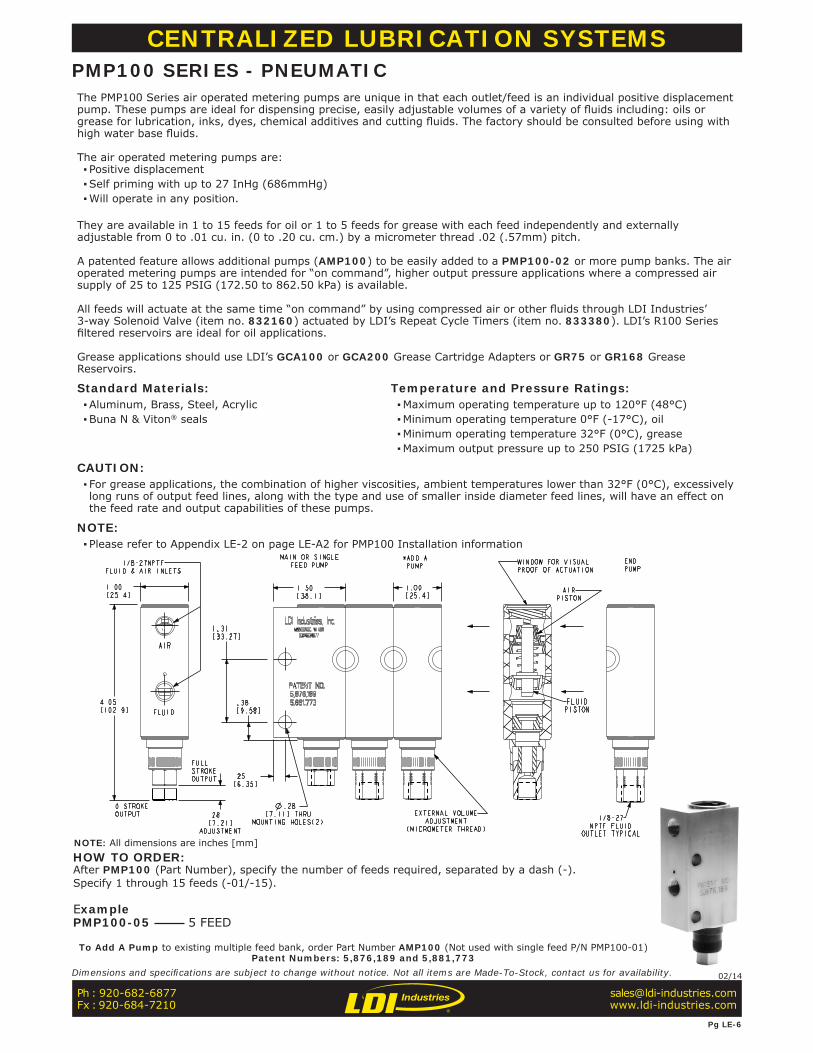
CENTRALIZED LUBRICATION SYSTEMSPMP100 SERIES - PNEUMATICThe PMP100 Series air operated metering pumps are unique in that each outlet/feed is an individual positive displacement pump. These pumps are ideal for dispensing precise, easily adjustable volumes of a variety of fl uids including: oils or grease for lubrication, inks, dyes, chemical additives and cutting fl uids. The factory should be consulted before using with high water base fl uids.
The air operated metering pumps are: ▪ Positive displacement ▪Self priming with up to 27 InHg (686mmHg) ▪Will operate in any position.
They are available in 1 to 15 feeds for oil or 1 to 5 feeds for grease with each feed independently and externally adjustable from 0 to .01 cu. in. (0 to .20 cu. cm.) by a micrometer thread .02 (.57mm) pitch.
A patented feature allows additional pumps (AMP100) to be easily added to a PMP100-02 or more pump banks. The air operated metering pumps are intended for “on command”, higher output pressure applications where a compressed air supply of 25 to 125 PSIG (172.50 to 862.50 kPa) is available.
All feeds will actuate at the same time “on command” by using compressed air or other fl uids through LDI Industries’ 3-way Solenoid Valve (item no. 832160) actuated by LDI’s Repeat Cycle Timers (item no. 833380). LDI’s R100 Series fi ltered reservoirs are ideal for oil applications.
Grease applications should use LDI’s GCA100 or GCA200 Grease Cartridge Adapters or GR75 or GR168 Grease Reservoirs.
Standard Materials: ▪Aluminum, Brass, Steel, Acrylic ▪Buna N & Viton® seals
Temperature and Pressure Ratings: ▪Maximum operating temperature up to 120°F (48°C) ▪Minimum operating temperature 0°F (-17°C), oil ▪Minimum operating temperature 32°F (0°C), grease ▪Maximum output pressure up to 250 PSIG (1725 kPa)
CAUTION: ▪ For grease applications, the combination of higher viscosities, ambient temperatures lower than 32°F (0°C), excessively long runs of output feed lines, along with the type and use of smaller inside diameter feed lines, will have an effect on the feed rate and output capabilities of these pumps.
NOTE: ▪ Please refer to Appendix LE-2 on page LE-A2 for PMP100 Installation information
To Add A Pump to existing multiple feed bank, order Part Number AMP100 (Not used with single feed P/N PMP100-01)Patent Numbers: 5,876,189 and 5,881,773
HOW TO ORDER:After PMP100 (Part Number), specify the number of feeds required, separated by a dash (-).Specify 1 through 15 feeds (-01/-15).
ExamplePMP100-05 5 FEED
Ph : 920-682-6877Fx : 920-684-7210
Pg LE-6
Dimensions and specifi cations are subject to change without notice. Not all items are Made-To-Stock, contact us for availability. 02/14
NOTE: All dimensions are inches [mm]

CENTRALIZED LUBRICATION SYSTEMSPMP200 SERIES - ELECTRICMotor operated metering pumps are unique in that each outlet/feed is an individual positive displacement pump. These pumps are ideal for dispensing precise easily adjustable volumes of a variety of fl uids including: oils or grease for lubrication, inks, dyes, chemical additives and cutting fl uids. The factory should be consulted before using with high water base fl uids.
The motor operated metering pumps are: ▪ Positive displacement, self priming with up to 27 InHg (686mmHg) ▪Will operate in any position. ▪Are available in 1 to 4 pumps with each pump independently and externally adjustable from 0 to .01 cu. in. (0 to .20 cu. cm.) by a micrometer thread .02 (.57mm) pitch. ▪Each pump will actuate once per minute of motor run time. The motor operated metering pumps are intended for lower output pressure applications or where a compressed air supply is not available. ▪Oil applications should use R100 series filtered reservoirs. ▪Grease applications should use GCA100 or GCA200, GR75 or GR168 Grease Reservoirs.
Standard Materials: ▪Aluminum, Brass, Steel, Acrylic ▪Buna N & Viton® seals
Temperature and Pressure Ratings: ▪Maximum operating temperature up to 120°F (48°C) ▪Minimum operating temperature 0°F (-17°C), oil ▪Minimum operating temperature 32°F (0°C), grease ▪Maximum output pressure up to 50 PSIG (345 kPa) ▪120V, 60Hz, 4W
CAUTION: ▪ For grease applications, the combination of higher viscosities, ambient temperatures lower than 32°F (0°C), excessively long runs of output feed lines, along with the type and use of smaller inside diameter feed lines, will have an effect on the feed rate and output capabilities of these pumps
Patent Number: 5,876,189
HOW TO ORDER:After PMP200 (Part Number), specify the number of feeds required, separated by a dash (-).Specify 1 through 4 feeds (-01/-04).
ExamplePMP200-04 4 FEED (shown)
Ph : 920-682-6877Fx : 920-684-7210
Pg LE-7
Dimensions and specifi cations are subject to change without notice. Not all items are Made-To-Stock, contact us for availability. 02/14
NOTE: All dimensions are inches [mm]
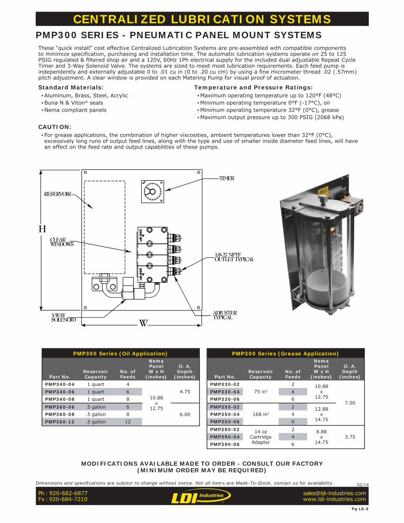
PMP300 Series (Oil Application)
Part No.ReservoirCapacity
No. ofFeeds
NemaPanelW x H
(inches)
O. A.Depth
(inches)PMP340-04 1 quart 4
10.88x
12.75
4.75PMP340-06 1 quart 6PMP340-08 1 quart 8
PMP360-06 .5 gallon 66.00PMP360-08 .5 gallon 8
PMP360-12 .5 gallon 12
PMP300 Series (Grease Application)
Part No.ReservoirCapacity
No. ofFeeds
NemaPanelW x H
(inches)
O. A.Depth
(inches)PMP330-02
75 in3
2 10.88x
12.757.00
PMP330-04 4PMP330-06 6
PMP350-02168 in3
2 12.88x
14.75PMP350-04 4PMP350-06 6
PMP390-02 14 ozCartridgeAdapter
2 8.88x
14.753.75PMP390-04 4
PMP390-06 6
W
H
TIMER
CLEAR WINDOWS
3-WAYSOLENOID
1/8-27 NPTFOUTLET TYPICAL
ADJUSTERTYPICAL
RESERVOIR
CENTRALIZED LUBRICATION SYSTEMSPMP300 SERIES - PNEUMATIC PANEL MOUNT SYSTEMSThese “quick install” cost effective Centralized Lubrication Systems are pre-assembled with compatible components to minimize specifi cation, purchasing and installation time. The automatic lubrication systems operate on 25 to 125 PSIG regulated & fi ltered shop air and a 120V, 60Hz 1Ph electrical supply for the included dual adjustable Repeat Cycle Timer and 3-Way Solenoid Valve. The systems are sized to meet most lubrication requirements. Each feed pump is independently and externally adjustable 0 to .01 cu in (0 to .20 cu cm) by using a fi ne micrometer thread .02 (.57mm) pitch adjustment. A clear window is provided on each Metering Pump for visual proof of actuation.
Standard Materials: ▪Aluminum, Brass, Steel, Acrylic ▪Buna N & Viton® seals ▪Nema compliant panels
Temperature and Pressure Ratings: ▪Maximum operating temperature up to 120°F (48°C) ▪Minimum operating temperature 0°F (-17°C), oil ▪Minimum operating temperature 32°F (0°C), grease ▪Maximum output pressure up to 300 PSIG (2068 kPa)
CAUTION: ▪ For grease applications, the combination of higher viscosities, ambient temperatures lower than 32°F (0°C), excessively long runs of output feed lines, along with the type and use of smaller inside diameter feed lines, will have an effect on the feed rate and output capabilities of these pumps.
MODIFICATIONS AVAILABLE MADE TO ORDER - CONSULT OUR FACTORY(MINIMUM ORDER MAY BE REQUIRED)
Ph : 920-682-6877Fx : 920-684-7210
Pg LE-8
Dimensions and specifi cations are subject to change without notice. Not all items are Made-To-Stock, contact us for availability. 02/14
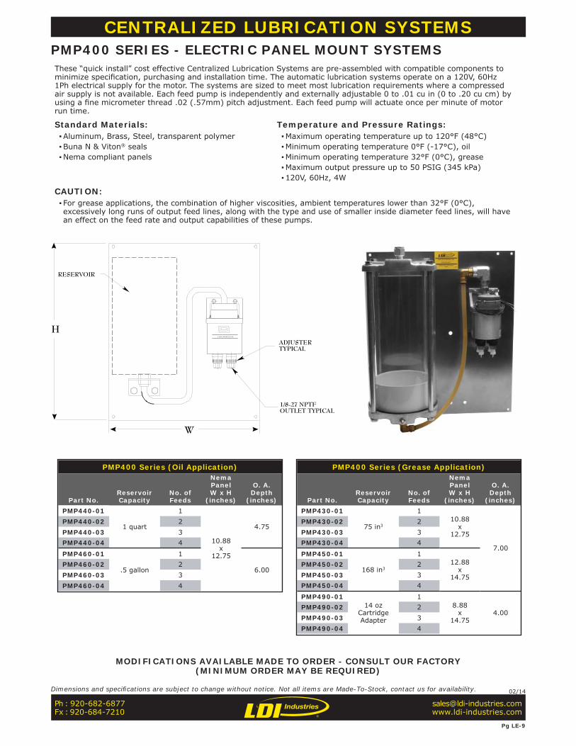
RESERVOIR
ADJUSTERTYPICAL
1/8-27 NPTFOUTLET TYPICAL
W
HLUBE DEVICES, I NC.
CENTRALIZED LUBRICATION SYSTEMSPMP400 SERIES - ELECTRIC PANEL MOUNT SYSTEMSThese “quick install” cost effective Centralized Lubrication Systems are pre-assembled with compatible components to minimize specifi cation, purchasing and installation time. The automatic lubrication systems operate on a 120V, 60Hz 1Ph electrical supply for the motor. The systems are sized to meet most lubrication requirements where a compressed air supply is not available. Each feed pump is independently and externally adjustable 0 to .01 cu in (0 to .20 cu cm) by using a fi ne micrometer thread .02 (.57mm) pitch adjustment. Each feed pump will actuate once per minute of motor run time.
Standard Materials: ▪Aluminum, Brass, Steel, transparent polymer ▪Buna N & Viton® seals ▪Nema compliant panels
Temperature and Pressure Ratings: ▪Maximum operating temperature up to 120°F (48°C) ▪Minimum operating temperature 0°F (-17°C), oil ▪Minimum operating temperature 32°F (0°C), grease ▪Maximum output pressure up to 50 PSIG (345 kPa) ▪120V, 60Hz, 4W
CAUTION: ▪ For grease applications, the combination of higher viscosities, ambient temperatures lower than 32°F (0°C), excessively long runs of output feed lines, along with the type and use of smaller inside diameter feed lines, will have an effect on the feed rate and output capabilities of these pumps.
PMP400 Series (Oil Application)
Part No.ReservoirCapacity
No. ofFeeds
NemaPanelW x H
(inches)
O. A.Depth
(inches)PMP440-01
1 quart
1
10.88x
12.75
4.75PMP440-02 2PMP440-03 3PMP440-04 4
PMP460-01
.5 gallon
1
6.00PMP460-02 2PMP460-03 3PMP460-04 4
PMP400 Series (Grease Application)
Part No.ReservoirCapacity
No. ofFeeds
NemaPanelW x H
(inches)
O. A.Depth
(inches)PMP430-01
75 in3
110.88
x12.75
7.00
PMP430-02 2PMP430-03 3PMP430-04 4
PMP450-01
168 in3
112.88
x14.75
PMP450-02 2PMP450-03 3PMP450-04 4
PMP490-0114 oz
CartridgeAdapter
18.88
x14.75
4.00PMP490-02 2PMP490-03 3PMP490-04 4
MODIFICATIONS AVAILABLE MADE TO ORDER - CONSULT OUR FACTORY(MINIMUM ORDER MAY BE REQUIRED)
Ph : 920-682-6877Fx : 920-684-7210
Pg LE-9
Dimensions and specifi cations are subject to change without notice. Not all items are Made-To-Stock, contact us for availability. 02/14
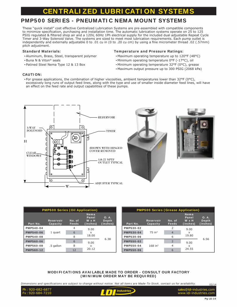
SHOWN WITH HINGEDCOVER REMOVED
RESERVOIR
CLEARWINDOWS
3-WAYSOLENOID TIMER
1/8-27 NPTFOUTLET TYPICAL
ADJUSTER TYPICALW
H
PMP500 Series (Grease Application)
Part No.ReservoirCapacity
No. ofFeeds
NemaPanelW x H
(inches)
O. A.Depth
(inches)PMP530-02
75 in3
2 9.00x
19.806.56
PMP530-04 4PMP530-06 6
PMP550-02168 in3
2 9.00x
24.55PMP550-04 4PMP550-06 6
PMP500 Series (Oil Application)
Part No.ReservoirCapacity
No. ofFeeds
NemaPanelW x H
(inches)
O. A.Depth
(inches)PMP540-04
1 quart4 9.00
x18.00
6.38
PMP540-06 6PMP540-08 8
PMP560-06.5 gallon
6 9.00x
20.12PMP560-08 8PMP560-12 12
CENTRALIZED LUBRICATION SYSTEMSPMP500 SERIES - PNEUMATIC NEMA MOUNT SYSTEMSThese “quick install” cost effective Centralized Lubrication Systems are pre-assembled with compatible components to minimize specifi cation, purchasing and installation time. The automatic lubrication systems operate on 25 to 125 PSIG regulated & fi ltered shop air and a 120V, 60Hz 1Ph electrical supply for the included dual adjustable Repeat Cycle Timer and 3-Way Solenoid Valve. The systems are sized to meet most lubrication requirements. Each pump outlet is independently and externally adjustable 0 to .01 cu in (0 to .20 cu cm) by using a fi ne micrometer thread .02 (.57mm) pitch adjustment.
Standard Materials: ▪Aluminum, Brass, Steel, transparent polymer ▪Buna N & Viton® seals ▪ Patined Steel Nema Type 12 & 13 Box
Temperature and Pressure Ratings: ▪Maximum operating temperature up to 120°F (48°C) ▪Minimum operating temperature 0°F (-17°C), oil ▪Minimum operating temperature 32°F (0°C), grease ▪Maximum output pressure up to 300 PSIG (2068 kPa)
CAUTION: ▪ For grease applications, the combination of higher viscosities, ambient temperatures lower than 32°F (0°C), excessively long runs of output feed lines, along with the type and use of smaller inside diameter feed lines, will have an effect on the feed rate and output capabilities of these pumps.
MODIFICATIONS AVAILABLE MADE TO ORDER - CONSULT OUR FACTORY(MINIMUM ORDER MAY BE REQUIRED)
Ph : 920-682-6877Fx : 920-684-7210
Pg LE-10
Dimensions and specifi cations are subject to change without notice. Not all items are Made-To-Stock, contact us for availability. 02/14
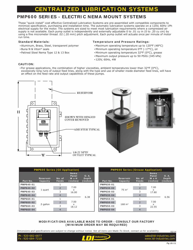
PMP600 Series (Oil Application)
Part No.ReservoirCapacity
No. ofFeeds
NemaPanelW x H
(inches)
O. A.Depth
(inches)PMP640-01
1 quart
17.00
x16.00
6.38
PMP640-02 2PMP640-03 3PMP640-04 4
PMP660-01
.5 gallon
17.00
x18.12
PMP660-02 2PMP660-03 3PMP660-04 4
PMP600 Series (Grease Application)
Part No.ReservoirCapacity
No. ofFeeds
NemaPanelW x H
(inches)
O. A.Depth
(inches)PMP630-01
75 in3
17.00
x17.80
6.56
PMP630-02 2PMP630-03 3PMP630-04 4
PMP650-01
168 in3
17.00
x22.55
PMP650-02 2PMP650-03 3PMP650-04 4
ADJUSTER TYPICAL
1/8-27 NPTFOUTLET TYPICAL
RESERVOIR
SHOWN WITH HINGEDCOVER REMOVED
H
W
LUBE DEVICES, INC.
CENTRALIZED LUBRICATION SYSTEMSPMP600 SERIES - ELECTRIC NEMA MOUNT SYSTEMSThese “quick install” cost effective Centralized Lubrication Systems are pre-assembled with compatible components to minimize specifi cation, purchasing and installation time. The automatic lubrication systems operate on a 120V, 60Hz 1Ph electrical supply for the motor. The systems are sized to meet most lubrication requirements where a compressed air supply is not available. Each pump outlet is independently and externally adjustable 0 to .01 cu in (0 to .20 cu cm) by using a fi ne micrometer thread .02 (.20 mm) pitch adjustment. Each pump outlet will actuate once per minute of motor run time.
Standard Materials: ▪Aluminum, Brass, Steel, transparent polymer ▪Buna N & Viton® seals ▪ Patined Steel Nema Type 12 & 13 Box
Temperature and Pressure Ratings: ▪Maximum operating temperature up to 120°F (48°C) ▪Minimum operating temperature 0°F (-17°C), oil ▪Minimum operating temperature 32°F (0°C), grease ▪Maximum output pressure up to 50 PSIG (345 kPa) ▪120V, 60Hz, 4W
CAUTION: ▪ For grease applications, the combination of higher viscosities, ambient temperatures lower than 32°F (0°C), excessively long runs of output feed lines, along with the type and use of smaller inside diameter feed lines, will have an effect on the feed rate and output capabilities of these pumps.
MODIFICATIONS AVAILABLE MADE TO ORDER - CONSULT OUR FACTORY(MINIMUM ORDER MAY BE REQUIRED)
Ph : 920-682-6877Fx : 920-684-7210
Pg LE-11
Dimensions and specifi cations are subject to change without notice. Not all items are Made-To-Stock, contact us for availability. 02/14

CENTRALIZED LUBRICATION SYSTEMSREPEAT CYCLE TIMERThis versatile timer is ideal for controlling the 3-Way Normally Closed Air Solenoid Valve (Part No: 832160) used to activate PMP100 when a PLC, touch activated switch, photo cell or proximity sensor are not available.
Standard Materials: ▪Molded plastic ▪Screw terminals ▪Operating instructions included ▪Mounting hardware not furnished ▪8-Pin mounting base
NOTE: ▪Recommended for use with PMP100 grease applications
Standard Features: ▪ “On time” setting energizes the solenoid valve which activates the PMP100. ▪ ”Off time” setting de-energizes the solenoid valve which allows the PMP100 to reset for the next cycle and controls when that next cycle will occur. ▪Will accommodate most industrial applications. ▪Can be wired through a relay so it is only active when the “machine” to be lubricated by the PMP100 is actually running; or, it can be wired uninterrupted for continual operation.
Operating Conditions: ▪ For operation on 100 to 240V, 60Hz, 1Ph ▪Output DPDT rated 5A max @ 240V, 60Hz, 1Ph ▪ Independently adjustable on time & off time by multiple ranges of 1.20 seconds to 300 hours ▪0.10 to 10.10 minute adjustable off time ▪14°F(-10°C) to 131°F(55°C) operating temperature
Repeat Cycle Timer
Part No.833380
Ph : 920-682-6877Fx : 920-684-7210
Pg LE-12
Dimensions and specifi cations are subject to change without notice. Not all items are Made-To-Stock, contact us for availability. 02/14
NOTE: All dimensions are inches [mm]
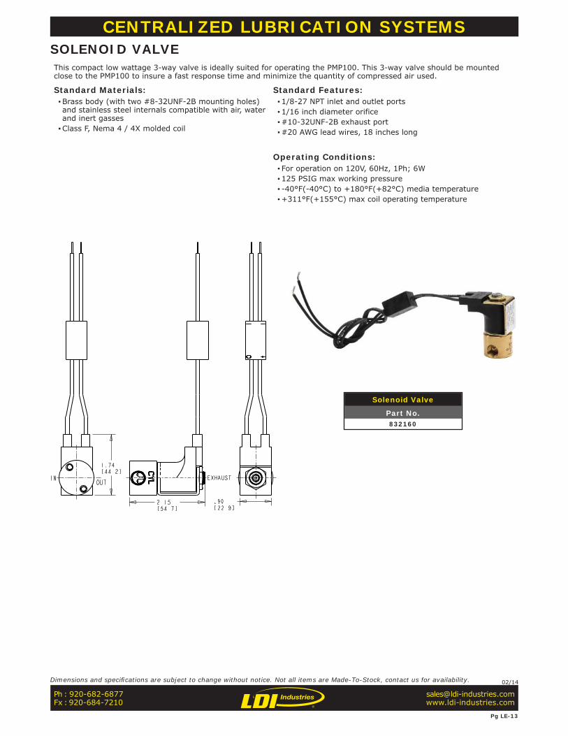
CENTRALIZED LUBRICATION SYSTEMSSOLENOID VALVEThis compact low wattage 3-way valve is ideally suited for operating the PMP100. This 3-way valve should be mounted close to the PMP100 to insure a fast response time and minimize the quantity of compressed air used.
Standard Materials: ▪Brass body (with two #8-32UNF-2B mounting holes) and stainless steel internals compatible with air, water and inert gasses ▪Class F, Nema 4 / 4X molded coil
Standard Features: ▪1/8-27 NPT inlet and outlet ports ▪1/16 inch diameter orifice ▪#10-32UNF-2B exhaust port ▪#20 AWG lead wires, 18 inches long
Operating Conditions: ▪ For operation on 120V, 60Hz, 1Ph; 6W ▪125 PSIG max working pressure ▪ -40°F(-40°C) to +180°F(+82°C) media temperature ▪+311°F(+155°C) max coil operating temperature
Solenoid Valve
Part No.832160
Ph : 920-682-6877Fx : 920-684-7210
Pg LE-13
Dimensions and specifi cations are subject to change without notice. Not all items are Made-To-Stock, contact us for availability. 02/14
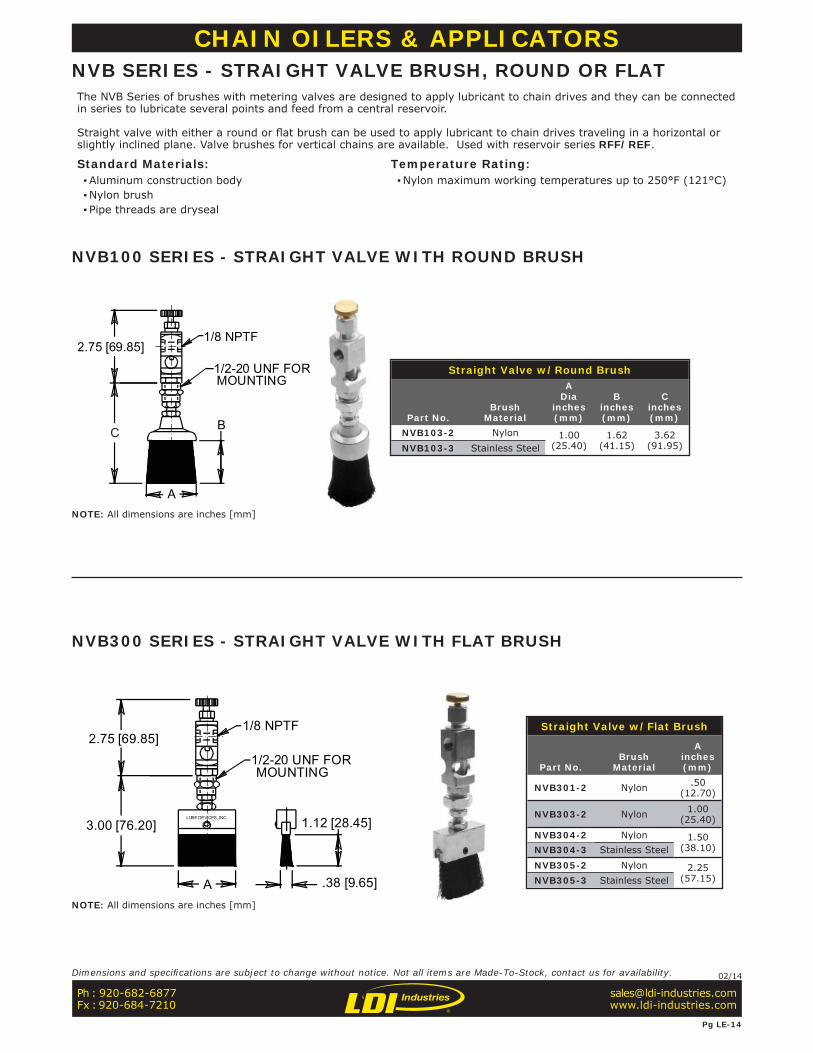
Straight Valve w/Round Brush
Part No.Brush
Material
ADia
inches(mm)
Binches(mm)
Cinches(mm)
NVB103-2 Nylon 1.00(25.40)
1.62(41.15)
3.62(91.95)NVB103-3 Stainless Steel
1/8 NPTF
1/2-20 UNF FOR MOUNTING
2.75 [69.85]
C B
A
CHAIN OILERS & APPLICATORSNVB SERIES - STRAIGHT VALVE BRUSH, ROUND OR FLATThe NVB Series of brushes with metering valves are designed to apply lubricant to chain drives and they can be connected in series to lubricate several points and feed from a central reservoir.
Straight valve with either a round or fl at brush can be used to apply lubricant to chain drives traveling in a horizontal or slightly inclined plane. Valve brushes for vertical chains are available. Used with reservoir series RFF/REF.
Standard Materials: ▪Aluminum construction body ▪Nylon brush ▪ Pipe threads are dryseal
Temperature Rating: ▪Nylon maximum working temperatures up to 250°F (121°C)
Straight Valve w/Flat Brush
Part No.Brush
Material
Ainches(mm)
NVB301-2 Nylon .50(12.70)
NVB303-2 Nylon 1.00(25.40)
NVB304-2 Nylon 1.50(38.10)NVB304-3 Stainless Steel
NVB305-2 Nylon 2.25(57.15)NVB305-3 Stainless Steel
1/8 NPTF
LUBE DEVICES, INC.
1/2-20 UNF FOR MOUNTING
2.75 [69.85]
.38 [9.65]
1.12 [28.45]3.00 [76.20]
A
NVB100 SERIES - STRAIGHT VALVE WITH ROUND BRUSH
NVB300 SERIES - STRAIGHT VALVE WITH FLAT BRUSH
Ph : 920-682-6877Fx : 920-684-7210
Pg LE-14
Dimensions and specifi cations are subject to change without notice. Not all items are Made-To-Stock, contact us for availability. 02/14
NOTE: All dimensions are inches [mm]
NOTE: All dimensions are inches [mm]
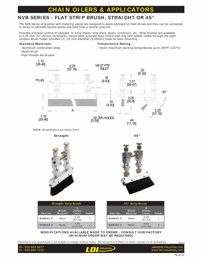
Straight Strip Brush 45° Strip Brush
Part no.Brush
Material
Ainches(mm) Feeds Part No.
BrushMaterial
Ainches(mm) Feeds
NVB201-2 Nylon 2.25(57.15) 1 NVB251-2 Nylon 2.25
(57.15) 1
NVB202-2 Nylon 4.50(114.30) 2 NVB252-2 Nylon 4.50
(114.30) 2
PLUG
.22 DIA.HOLES
1/8-27 PTFINLET
45
A
1.12[28.45] 2.25
[57.15]
1.16[29.46]
.19[4.83]
.19[4.83]
[5.59]
3.31[84.07]
.25[6.35]
2.00[50.8]
.44 [11.18]
2.25[57.15]
CHAIN OILERS & APPLICATORSNVB SERIES - FLAT STRIP BRUSH, STRAIGHT OR 45°The NVB Series of brushes with metering valves are designed to apply lubricant to chain drives and they can be connected in series to lubricate several points and feed from a central reservoir.
Provides precision control of lubricant to drive chains, strip stock, gears, conveyors, etc. Strip brushes are available in 2.25 inch (57.15mm) increments. Valves allow accurate feed control with drip rate readily visible through the sight window. Brush holder provides (2) .22 inch diameter (5.59mm) holes for easy mounting.
Standard Materials: ▪Aluminum construction body ▪Nylon brush ▪ Pipe threads are dryseal
Temperature Rating: ▪Nylon maximum working temperatures up to 250°F (121°C)
MODIFICATIONS AVAILABLE MADE TO ORDER - CONSULT OUR FACTORY(MINIMUM ORDER MAY BE REQUIRED)
Straight 45°
Ph : 920-682-6877Fx : 920-684-7210
Pg LE-15
Dimensions and specifi cations are subject to change without notice. Not all items are Made-To-Stock, contact us for availability. 02/14
NOTE: All dimensions are inches [mm]
1/2-20 FOR MOUNTING
1/8 NPTF
A - BRUSH SIZE
1.19 [30.23] MIN
45
2.88 [73.15]
1.12 [28.45]
3.62 [91.95] MIN
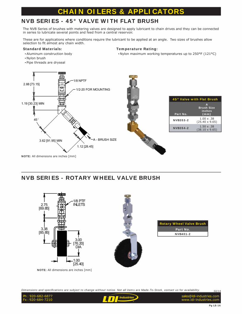
45° Valve with Flat Brush
Part No.
ABrush Size
inches(mm)
NVB353-2 1.00 x .38(25.40 x 9.65)
NVB354-2 1.50 x .38(38.10 x 9.65)
CHAIN OILERS & APPLICATORSNVB SERIES - 45° VALVE WITH FLAT BRUSHThe NVB Series of brushes with metering valves are designed to apply lubricant to chain drives and they can be connected in series to lubricate several points and feed from a central reservoir.
These are for applications where conditions require the lubricant to be applied at an angle. Two sizes of brushes allow selection to fi t almost any chain width.
Standard Materials: ▪Aluminum construction body ▪Nylon brush ▪ Pipe threads are dryseal
Temperature Rating: ▪Nylon maximum working temperatures up to 250°F (121°C)
NVB SERIES - ROTARY WHEEL VALVE BRUSH
Rotary Wheel Valve Brush
Part No.NVB401-2
2.75[69.85]
3.38[85.85]
1.00[25.40]
3.00[76.20]
DIA
1/8 PTFINLETS
Ph : 920-682-6877Fx : 920-684-7210
Pg LE-16
Dimensions and specifi cations are subject to change without notice. Not all items are Made-To-Stock, contact us for availability. 02/14
NOTE: All dimensions are inches [mm]
NOTE: All dimensions are inches [mm]
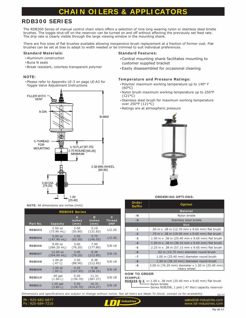
RDB300 Series
Part No. Capacity
Ainches(mm)
Binches(mm)
CThread
UNF
RDB303 2.50 oz(73.90 mL)
2.00(50.80)
5.19(131.83) 1/2-20
RDB304 5.00 oz(147.90 mL)
2.50(63.50)
5.75(146.05) 1/2-20
RDB306 9.00 oz(266.20 mL)
3.00(76.20)
7.00(177.80) 5/8-18
RDB307 12.00 oz(354.90 mL)
3.00(76.20)
8.38(212.85) 5/8-18
RDB308 1.00 pt(.47 L)
3.50(88.90)
8.38(212.85) 5/8-18
RDB309 1.00 qt(.95 L)
4.25(107.95)
9.38(238.25) 5/8-18
RDB310 .50 gal(1.90 L)
5.50(139.70)
11.31(287.27) 5/8-18
RDB311 1.00 gal(3.80 L)
5.50(139.70)
16.31(414.27) 5/8-18
[25.40]
[76.20]3.00 DIA
3.38 MIN.WHEEL
3.19 FLAT3.75 ROUND
MINIMUM
C-THREADFOR
MOUNTING
B-MAX
A-DIA
FILLER WITHVENT
1.00
[85.85]
[81.03][95.25]
CHAIN OILERS & APPLICATORSRDB300 SERIESThe RDB300 Series of manual control chain oilers offers a selection of nine long wearing nylon or stainless steel bristle brushes. The toggle shut-off on the reservoir can be turned on and off without affecting the previously set feed rate. The drip rate is clearly visible through the large viewing window in the mounting shank.
There are fi ve sizes of fl at brushes available allowing inexpensive brush replacement at a fraction of former cost. Flat brushes can be set at bias to adapt to width needed or be trimmed to suit individual preferences.
Standard Materials: ▪Aluminum construction ▪Buna N seals ▪Break resistant, colorless transparent polymer
NOTE: ▪ Please refer to Appendix LE-3 on page LE-A3 for Toggle Valve Adjustment Instructions
Standard Features: ▪Central mounting shank facilitates mounting to customer supplied bracket ▪Easily disassembled for occasional cleaning
Temperature and Pressure Ratings: ▪ Polymer maximum working temperature up to 140° F (60°C) ▪Nylon brush maximum working temperature up to 250°F (121°C) ▪Stainless steel brush for maximum working temperature over 250°F (121°C) ▪Ratings are at atmospheric pressure
ORDERING OPTIONS:
OrderSuffi x Option
Material-N Nylon bristle-S Stainless steel bristle
Size-1 .50 in x .38 in (12.70 mm x 9.65 mm) fl at brush-2 .75 in x .38 in (19.05 mm x 9.65 mm) fl at brush-3 1.00 in x .38 in (25.40 mm x 9.65 mm) fl at brush-4 1.50 in x .38 in (38.10 mm x 9.65 mm) fl at brush-5 2.25 in x .38 in (57.15 mm x 9.65 mm) fl at brush-6 .62 in (15.75 mm) diameter round brush-7 1.00 in (25.40 mm) diameter round brush-8 1.50 in (38.10 mm) diameter round brush-9 3.00 in (76.20 mm) diameter x 1.00 in (25.40 mm)
rotary wheel
HOW TO ORDEREXAMPLE:RDB308-N-3 1.00 x .38 inch (25.40 mm x 9.65 mm) fl at brush
Nylon bristleSeries RDB308, 1 pint (.47 liter) capacity reservoir
Ph : 920-682-6877Fx : 920-684-7210
Pg LE-17
Dimensions and specifi cations are subject to change without notice. Not all items are Made-To-Stock, contact us for availability. 02/14
NOTE: All dimensions are inches [mm]
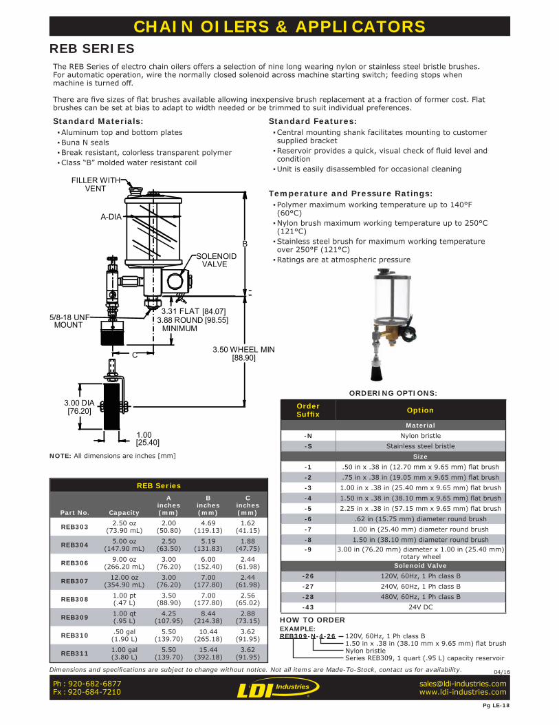
REB Series
Part No. Capacity
Ainches(mm)
Binches(mm)
Cinches(mm)
REB303 2.50 oz(73.90 mL)
2.00(50.80)
4.69(119.13)
1.62(41.15)
REB304 5.00 oz(147.90 mL)
2.50(63.50)
5.19(131.83)
1.88(47.75)
REB306 9.00 oz(266.20 mL)
3.00(76.20)
6.00(152.40)
2.44(61.98)
REB307 12.00 oz(354.90 mL)
3.00(76.20)
7.00(177.80)
2.44(61.98)
REB308 1.00 pt(.47 L)
3.50(88.90)
7.00(177.80)
2.56(65.02)
REB309 1.00 qt(.95 L)
4.25(107.95)
8.44(214.38)
2.88(73.15)
REB310 .50 gal(1.90 L)
5.50(139.70)
10.44(265.18)
3.62(91.95)
REB311 1.00 gal(3.80 L)
5.50(139.70)
15.44(392.18)
3.62(91.95)
FILLER WITHVENT
B
A-DIA
SOLENOIDVALVE
MOUNT
3.31 FLAT3.88 ROUND
MINIMUM
3.50 WHEEL MINC
3.00 DIA[76.20]
1.00[25.40]
5/8-18 UNF[84.07][98.55]
[88.90]
CHAIN OILERS & APPLICATORSREB SERIESThe REB Series of electro chain oilers offers a selection of nine long wearing nylon or stainless steel bristle brushes. For automatic operation, wire the normally closed solenoid across machine starting switch; feeding stops when machine is turned off. There are fi ve sizes of fl at brushes available allowing inexpensive brush replacement at a fraction of former cost. Flat brushes can be set at bias to adapt to width needed or be trimmed to suit individual preferences.
Standard Materials: ▪Aluminum top and bottom plates ▪Buna N seals ▪Break resistant, colorless transparent polymer ▪Class “B” molded water resistant coil
Standard Features: ▪Central mounting shank facilitates mounting to customer supplied bracket ▪Reservoir provides a quick, visual check of fl uid level and condition ▪Unit is easily disassembled for occasional cleaning
Temperature and Pressure Ratings: ▪ Polymer maximum working temperature up to 140°F (60°C) ▪Nylon brush maximum working temperature up to 250°C (121°C) ▪Stainless steel brush for maximum working temperature over 250°F (121°C) ▪Ratings are at atmospheric pressure
ORDERING OPTIONS:
OrderSuffi x Option
Material-N Nylon bristle-S Stainless steel bristle
Size-1 .50 in x .38 in (12.70 mm x 9.65 mm) fl at brush-2 .75 in x .38 in (19.05 mm x 9.65 mm) fl at brush-3 1.00 in x .38 in (25.40 mm x 9.65 mm) fl at brush-4 1.50 in x .38 in (38.10 mm x 9.65 mm) fl at brush-5 2.25 in x .38 in (57.15 mm x 9.65 mm) fl at brush-6 .62 in (15.75 mm) diameter round brush-7 1.00 in (25.40 mm) diameter round brush-8 1.50 in (38.10 mm) diameter round brush-9 3.00 in (76.20 mm) diameter x 1.00 in (25.40 mm)
rotary wheelSolenoid Valve
-26 120V, 60Hz, 1 Ph class B-27 240V, 60Hz, 1 Ph class B-28 480V, 60Hz, 1 Ph class B-43 24V DC
HOW TO ORDEREXAMPLE:REB309-N-4-26 120V, 60Hz, 1 Ph class B
1.50 in x .38 in (38.10 mm x 9.65 mm) fl at brushNylon bristleSeries REB309, 1 quart (.95 L) capacity reservoir
Ph : 920-682-6877Fx : 920-684-7210
Pg LE-18
Dimensions and specifi cations are subject to change without notice. Not all items are Made-To-Stock, contact us for availability. 04/16
NOTE: All dimensions are inches [mm]
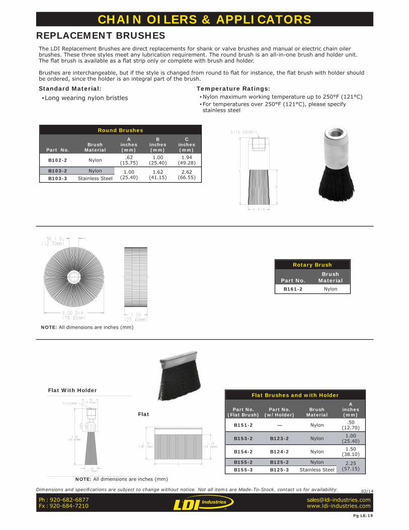
Round Brushes
Part No.Brush
Material
Ainches(mm)
Binches(mm)
Cinches(mm)
B102-2 Nylon .62(15.75)
1.00(25.40)
1.94(49.28)
B103-2 Nylon 1.00(25.40)
1.62(41.15)
2.62(66.55)B103-3 Stainless Steel
Rotary Brush
Part No.Brush
MaterialB161-2 Nylon
Flat Brushes and with Holder
Part No.(Flat Brush)
Part No.(w/Holder)
BrushMaterial
Ainches(mm)
B151-2 — Nylon .50(12.70)
B153-2 B123-2 Nylon 1.00(25.40)
B154-2 B124-2 Nylon 1.50(38.10)
B155-2 B125-2 Nylon 2.25(57.15)B155-3 B125-3 Stainless Steel
CHAIN OILERS & APPLICATORSREPLACEMENT BRUSHESThe LDI Replacement Brushes are direct replacements for shank or valve brushes and manual or electric chain oiler brushes. These three styles meet any lubrication requirement. The round brush is an all-in-one brush and holder unit. The fl at brush is available as a fl at strip only or complete with brush and holder.
Brushes are interchangeable, but if the style is changed from round to fl at for instance, the fl at brush with holder should be ordered, since the holder is an integral part of the brush.
Standard Material: ▪Long wearing nylon bristles
Temperature Ratings: ▪Nylon maximum working temperature up to 250°F (121°C) ▪ For temperatures over 250°F (121°C), please specify stainless steel
Flat With Holder
Flat
Ph : 920-682-6877Fx : 920-684-7210
Pg LE-19
Dimensions and specifi cations are subject to change without notice. Not all items are Made-To-Stock, contact us for availability. 02/14
NOTE: All dimensions are inches (mm)
NOTE: All dimensions are inches (mm)
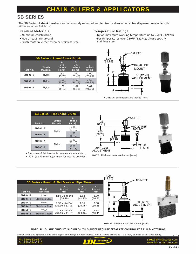
SB Series - Round Shank Brush
Part No.Brush
Material
ADia
inches(mm)
BDia
inches(mm)
Cinches(mm)
SB102-2 Nylon .62(15.75)
1.00(25.40)
3.00(76.20)
SB103-2 Nylon 1.00(25.40)
1.62(41.15)
3.62(91.95)
SB104-2 Nylon 1.50(38.10)
1.62(41.15)
3.62(91.95)
▪ Four sizes of flat insertable brushes are available ▪ .50 in (12.70 mm) adjustment for wear is provided
SB Series - Flat Shank Brush
Part No.Brush
Material
Ainches(mm)
SB301-2Nylon
.50(12.70)
SB303-2 1.00(25.40)
SB304-2Nylon
1.50(38.10)
SB305-2 2.25(57.15)
SB Series - Round & Flat Brush w/Pipe Thread
Part No.Brush
Material
Ainches(mm)
Binches(mm)
Cinches(mm)
SB204-2 Nylon 1.50 Dia round (38.10)
1.62(41.15)
3.00(76.20)SB204-3 Stainless Steel
SB354-2 Nylon 1.50 x .44 Flat (38.10 x 11.18)
1.16(29.46)
2.38(60.45)SB354-3 Stainless Steel
SB355-2 Nylon 2.25 x .44 Flat (57.15 x 11.18)
1.16(29.46)
2.38(60.45)SB355-3 Stainless Steel
1/2-20 UNFMOUNT
1/8 PTF
A
BC
1.25
.50 [12.70]ADJUSTMENT
[31.75]
1/8 PTF
1/2-20 UNFMOUNT
3.00
1.25
A
1.16
.50 [12.70].44
ADJUSTMENT
[31.75]
[11.18]
[76.20]
[29.46]
1/8 NPTF
A
C
B
1.25
.50 [12.70]
[12.70]
ADJUSTMENT
CHAIN OILERS & APPLICATORSSB SERIESThe SB Series of shank brushes can be remotely mounted and fed from valves on a central dispenser. Available with either round or fl at brush.
Standard Materials: ▪Aluminum construction ▪ Pipe threads are dryseal ▪Brush material either nylon or stainless steel
Temperature Ratings: ▪Nylon maximum working temperature up to 250°F (121°C) ▪ For temperatures over 250°F (121°C), please specify stainless steel
NOTE: ALL SHANK BRUSHES SHOWN ON THIS SHEET REQUIRE SEPARATE CONTROL FOR FLUID METERING
Ph : 920-682-6877Fx : 920-684-7210
Pg LE-20
Dimensions and specifi cations are subject to change without notice. Not all items are Made-To-Stock, contact us for availability. 02/14
NOTE: All dimensions are inches [mm]
NOTE: All dimensions are inches [mm]
NOTE: All dimensions are inches [mm]
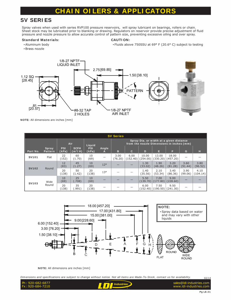
SV Series
Part No.Spray
Pattern
Air LiquidPSI
(kPa)Angle
A
Spray Dia. or width at a given distancefrom the nozzle Dimensions in inches (mm)
PSI(kPa)
SCFH(m3/H) B C D E F G H
SV101 Flat 22(152)
60(1.70)
10(69) — 3.00
(76.20)6.00
(152.40)10.00
(254.00)13.00
(330.20)18.00
(457.20) — —
SV102 Round
12(83)
45(1.27)
10(69) 12° — — 1.30
(33.02)1.90
(48.26)3.20
(81.28)3.60
(91.44)3.80
(96.52)20
(138)50
(1.42)20
(138) 13° — — 1.40(35.56)
2.10(53.34)
3.40(86.36)
3.90(99.06)
4.10(104.14)
SV103 WideRound
10(69)
25(.708)
10(69) — — — 5.50
(139.70)7.00
(177.80)9.00
(228.60) — —
20(138)
35(.991)
20(138) — — — 6.00
(152.40)7.50
(190.50)9.50
(241.30) — —
FLAT WIDEROUND
ROUND
18.0017.00
15.00
AED
CB
F HG
[457.20][431.80]
[381.00]9.00 [228.60]
6.00 [152.40]3.00 [76.20]
1.50 [38.10]
CHAIN OILERS & APPLICATORSSV SERIESSpray valves when used with series RVP100 pressure reservoirs, will spray lubricant on bearings, rollers or chain. Sheet stock may be lubricated prior to blanking or drawing. Regulators on reservoir provide precise adjustment of fl uid pressure and nozzle pressure to allow accurate control of pattern size, preventing excessive oiling and over spray.
Standard Materials: ▪Aluminum body ▪Brass nozzle
CAUTION: ▪ Fluids above 750SSU at 69° F (20.6° C) subject to testing
1/8-27 NPTFAIR INLET
1/8-27 NPTFLIQUID INLET
#8-32 TAP2 HOLES
1.12 SQ[28.45]
.81[20.57]
PATTERN
2.75 [69.85]1.50 [38.10]
Ph : 920-682-6877Fx : 920-684-7210
Pg LE-21
Dimensions and specifi cations are subject to change without notice. Not all items are Made-To-Stock, contact us for availability. 02/14
NOTE: All dimensions are inches [mm]
NOTE: All dimensions are inches [mm]
NOTE: ▪Spray data based on water and may vary with other liquids
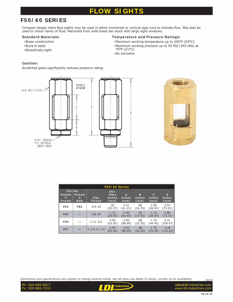
F50/60 SeriesPart No.
PipeThread
HexFlats
inches(mm)
Ainches(mm)
Binches(mm)
Cinches(mm)
Dinches(mm)
FemaleX
Female
FemaleX
Male
F52 F62 1/4-18 .81(20.57)
2.41(61.21)
.66(16.76)
1.06(26.92)
2.91(73.91)
F53 — 3/8-18 1.12(28.45)
2.38(60.45)
.69(17.53)
1.12(28.45)
2.88(73.15)
F56 — 1-11 1/2 2.50(63.50)
3.50(88.90)
.88(22.35)
1.75(44.45)
4.31(109.47)
F57 — 1 1/4-11 1/2 2.50(63.50)
3.50(88.90)
.88(22.35)
1.75(44.45)
4.34(110.24)
FLOW SIGHTSF50/60 SERIESCompact design inline fl ow sights may be used in either horizontal or vertical pipe runs to indicate fl ow. May also be used to check clarity of fl uid. Machined from solid brass bar stock with large sight windows.
Standard Materials: ▪Brass construction ▪Buna N seals ▪Borasilicate sight
Temperature and Pressure Ratings: ▪Maximum working temperature up to 200°F (93°C) ▪Maximum working pressure up to 50 PSI (345 kPa) at 70°F (21°C) ▪No corrosion
Caution:Scratched glass signifi cantly reduces pressure rating.
Ph : 920-682-6877Fx : 920-684-7210
Pg LE-22
Dimensions and specifi cations are subject to change without notice. Not all items are Made-To-Stock, contact us for availability. 02/14
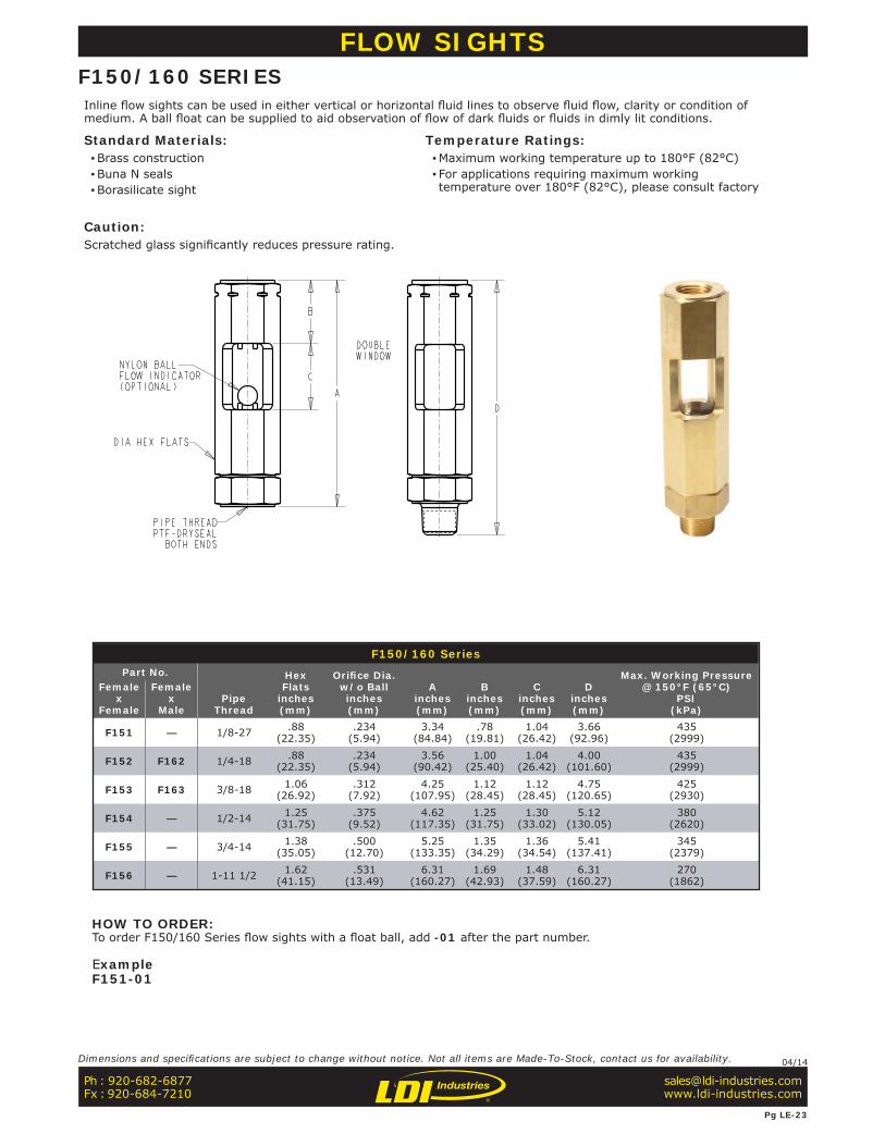
F150/160 SeriesPart No.
PipeThread
HexFlats
inches(mm)
Orifi ce Dia.w/o Ballinches(mm)
Ainches(mm)
Binches(mm)
Cinches(mm)
Dinches(mm)
Max. Working Pressure@ 150°F (65°C)
PSI(kPa)
Femalex
Female
Femalex
Male
F151 — 1/8-27 .88 (22.35)
.234 (5.94)
3.34(84.84)
.78(19.81)
1.04 (26.42)
3.66 (92.96)
435 (2999)
F152 F162 1/4-18 .88 (22.35)
.234 (5.94)
3.56(90.42)
1.00 (25.40)
1.04 (26.42)
4.00 (101.60)
435 (2999)
F153 F163 3/8-18 1.06(26.92)
.312 (7.92)
4.25 (107.95)
1.12 (28.45)
1.12 (28.45)
4.75 (120.65)
425 (2930)
F154 — 1/2-14 1.25(31.75)
.375 (9.52)
4.62 (117.35)
1.25 (31.75)
1.30 (33.02)
5.12 (130.05)
380 (2620)
F155 — 3/4-14 1.38(35.05)
.500 (12.70)
5.25 (133.35)
1.35 (34.29)
1.36 (34.54)
5.41 (137.41)
345 (2379)
F156 — 1-11 1/2 1.62(41.15)
.531 (13.49)
6.31 (160.27)
1.69(42.93)
1.48 (37.59)
6.31 (160.27)
270 (1862)
FLOW SIGHTSF150/160 SERIESInline fl ow sights can be used in either vertical or horizontal fl uid lines to observe fl uid fl ow, clarity or condition of medium. A ball fl oat can be supplied to aid observation of fl ow of dark fl uids or fl uids in dimly lit conditions.
Standard Materials: ▪Brass construction ▪Buna N seals ▪Borasilicate sight
Temperature Ratings: ▪Maximum working temperature up to 180°F (82°C) ▪ For applications requiring maximum working temperature over 180°F (82°C), please consult factory
Caution:Scratched glass signifi cantly reduces pressure rating.
Ph : 920-682-6877Fx : 920-684-7210
Pg LE-23
Dimensions and specifi cations are subject to change without notice. Not all items are Made-To-Stock, contact us for availability. 04/14
HOW TO ORDER:To order F150/160 Series fl ow sights with a fl oat ball, add -01 after the part number.
ExampleF151-01
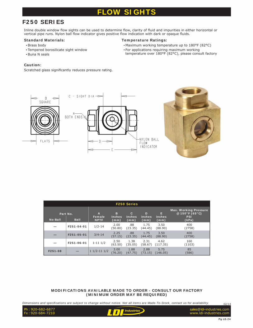
F250 Series
Part No. AFemaleNPTF
Binches(mm)
Cinches(mm)
Dinches (mm)
Einches(mm)
Max. Working Pressure@ 150°F (65°C)
PSI(kPa) No Ball Ball
— F251-04-01 1/2-14 2.00(50.80)
.88(23.35)
1.75(44.45)
3.50(88.90)
400 (2758)
— F251-05-01 3/4-14 2.25(57.15)
.88(23.35)
1.75(44.45)
3.50(88.90)
400 (2758)
— F251-06-01 1-11 1/2 2.50(63.50)
1.38(35.05)
2.31(58.67)
4.62(117.35)
160 (1103)
F251-08 — 1 1/2-11 1/2 3.00(76.20)
1.88(47.75)
2.88(73.15)
5.75(146.05)
85 (586)
FLOW SIGHTSF250 SERIESInline double window fl ow sights can be used to determine fl ow, clarity of fl uid and impurities in either horizontal or vertical pipe runs. Nylon ball fl ow indicator gives positive fl ow indication with dark or opaque fl uids.
Standard Materials: ▪Brass body ▪ Tempered borosilicate sight window ▪Buna N seals
Temperature Ratings: ▪Maximum working temperature up to 180°F (82°C) ▪ For applications requiring maximum working temperature over 180°F (82°C), please consult factory
Caution:Scratched glass signifi cantly reduces pressure rating.
Ph : 920-682-6877Fx : 920-684-7210
Pg LE-24
Dimensions and specifi cations are subject to change without notice. Not all items are Made-To-Stock, contact us for availability. 02/14
MODIFICATIONS AVAILABLE MADE TO ORDER - CONSULT OUR FACTORY(MINIMUM ORDER MAY BE REQUIRED)

F300 Series
Part No.
AFemaleNPTF
Binches(mm)
Cinches(mm)
Dinches(mm)
Einches(mm)
Max Working Pressure@ Temperature Shown
PSI(kPa)
°F(°C)
F301-04-01 1/2-14 1.75(44.45)
2.00(50.80)
1.44(36.58)
4.25(107.95)
130(896)
212(100)
F301-05-01 3/4-14 1.75(44.45)
2.00(50.80)
1.44(36.58)
4.25(107.95)
130(896)
212(100)
F301-06-01 1-11 1/2 1.75(44.45)
2.25(57.15)
1.75(44.45)
4.88(123.95)
130(896)
212(100)
F301-07-01 1 1/4-11 1/2 2.50(63.50)
3.00(76.20)
1.75(44.45)
5.62(142.75)
100(690)
185(85)
F301-08-01 1 1/2-11 1/2 2.50(63.50)
3.00(76.20)
1.88(47.75)
5.88(149.35)
100(690)
185(85)
F301-09-01 2-11 1/2 3.50(88.90)
4.00(101.60)
1.88(47.75)
7.50(190.50)
60(414)
150(65)
FLOW SIGHTSF300 SERIESWide view fl ow sights can be used in either horizontal or vertical pipe runs to observe fl uid fl ow clarity. Large cylindrical sight allows 360° viewing and fl ow is readily seen from a distance, in elevated or dimly lighted conditions. In vertical pipe run, fl uid fl ow should come in from bottom to note ball action as a fl ow indicator. The ball stop slightly restricts fl ow.
Standard Materials: ▪Brass construction ▪Borosilicate sight ▪Buna N seals ▪Nylon ball indicator
Temperature and Pressure Ratings: ▪Noted below in chart
Caution:Scratched glass signifi cantly reduces pressure rating.
Ph : 920-682-6877Fx : 920-684-7210
Pg LE-25
Dimensions and specifi cations are subject to change without notice. Not all items are Made-To-Stock, contact us for availability. 02/14
MODIFICATIONS AVAILABLE MADE TO ORDER - CONSULT OUR FACTORY(MINIMUM ORDER MAY BE REQUIRED)
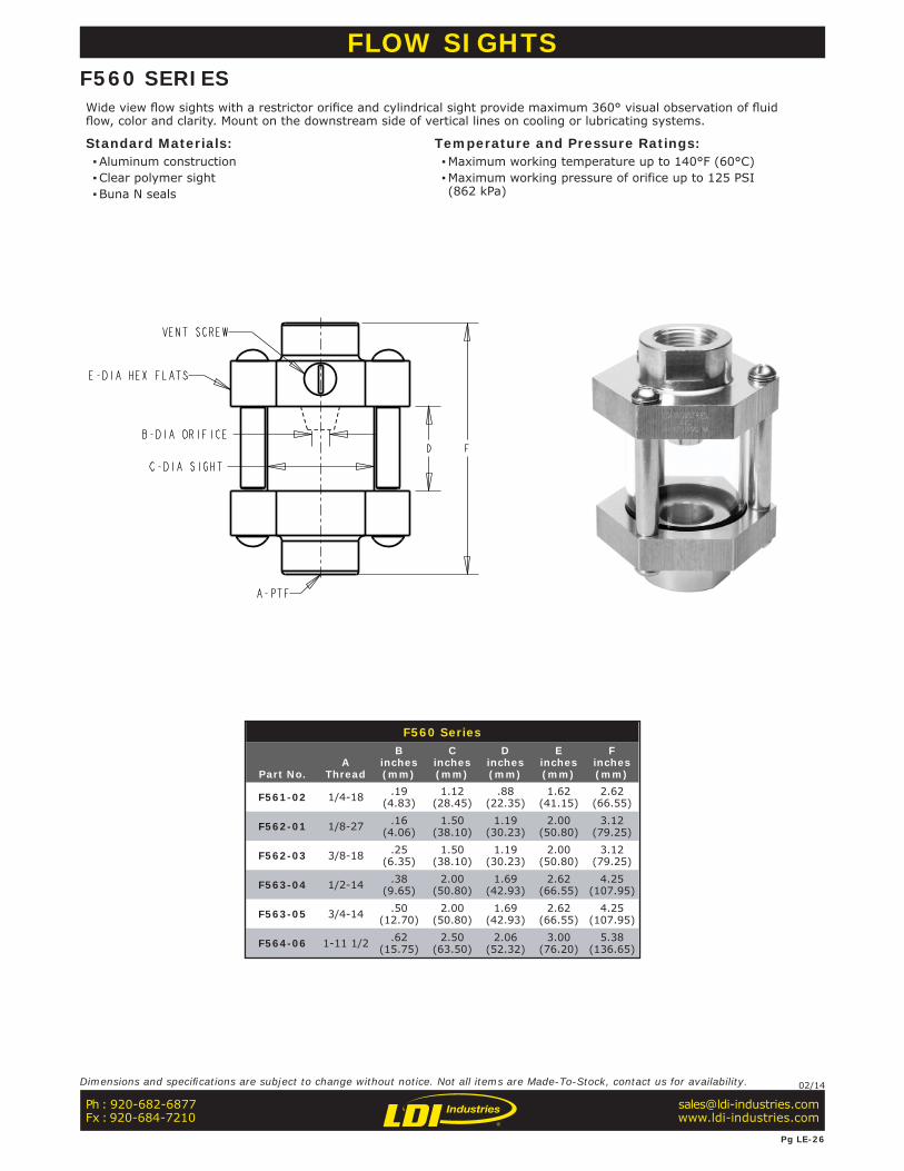
F560 Series
Part No.A
Thread
Binches(mm)
Cinches(mm)
Dinches(mm)
Einches(mm)
Finches(mm)
F561-02 1/4-18 .19(4.83)
1.12(28.45)
.88(22.35)
1.62(41.15)
2.62(66.55)
F562-01 1/8-27 .16(4.06)
1.50(38.10)
1.19(30.23)
2.00(50.80)
3.12(79.25)
F562-03 3/8-18 .25(6.35)
1.50(38.10)
1.19(30.23)
2.00(50.80)
3.12(79.25)
F563-04 1/2-14 .38(9.65)
2.00(50.80)
1.69(42.93)
2.62(66.55)
4.25(107.95)
F563-05 3/4-14 .50(12.70)
2.00(50.80)
1.69(42.93)
2.62(66.55)
4.25(107.95)
F564-06 1-11 1/2 .62(15.75)
2.50(63.50)
2.06(52.32)
3.00(76.20)
5.38(136.65)
FLOW SIGHTSF560 SERIESWide view fl ow sights with a restrictor orifi ce and cylindrical sight provide maximum 360° visual observation of fl uid fl ow, color and clarity. Mount on the downstream side of vertical lines on cooling or lubricating systems.
Standard Materials: ▪Aluminum construction ▪Clear polymer sight ▪Buna N seals
Temperature and Pressure Ratings: ▪Maximum working temperature up to 140°F (60°C) ▪Maximum working pressure of orifice up to 125 PSI (862 kPa)
Ph : 920-682-6877Fx : 920-684-7210
Pg LE-26
Dimensions and specifi cations are subject to change without notice. Not all items are Made-To-Stock, contact us for availability. 02/14

Inline Filter - Liquid
Part No.A
PTF
Binches(mm)
LF201-02 1/4-18 2.38(60.45)
LF201-03 3/8-18 2.62(66.55)
B
A
INLINE FILTER - LIQUIDThe Liquid Inline Filter can be used in liquid lines where dirt or particles could cause clogging, such as oil going to a spray valve. The inline cap can be taken off to clean the fi lter without dismantling unit from the line.
Standard Materials: ▪Brass construction ▪Buna N seals ▪40 micron filter
Temperate and Pressure Ratings: ▪Maximum working pressure up to 150 PSI (1034 kPa) ▪Maximum temperature up to 175°F (79°C)
Ph : 920-682-6877Fx : 920-684-7210
Pg LE-27
Dimensions and specifi cations are subject to change without notice. Not all items are Made-To-Stock, contact us for availability. 06/16
NOTE: All dimensions are inches (mm)
INLINE FILTER - LIQUID
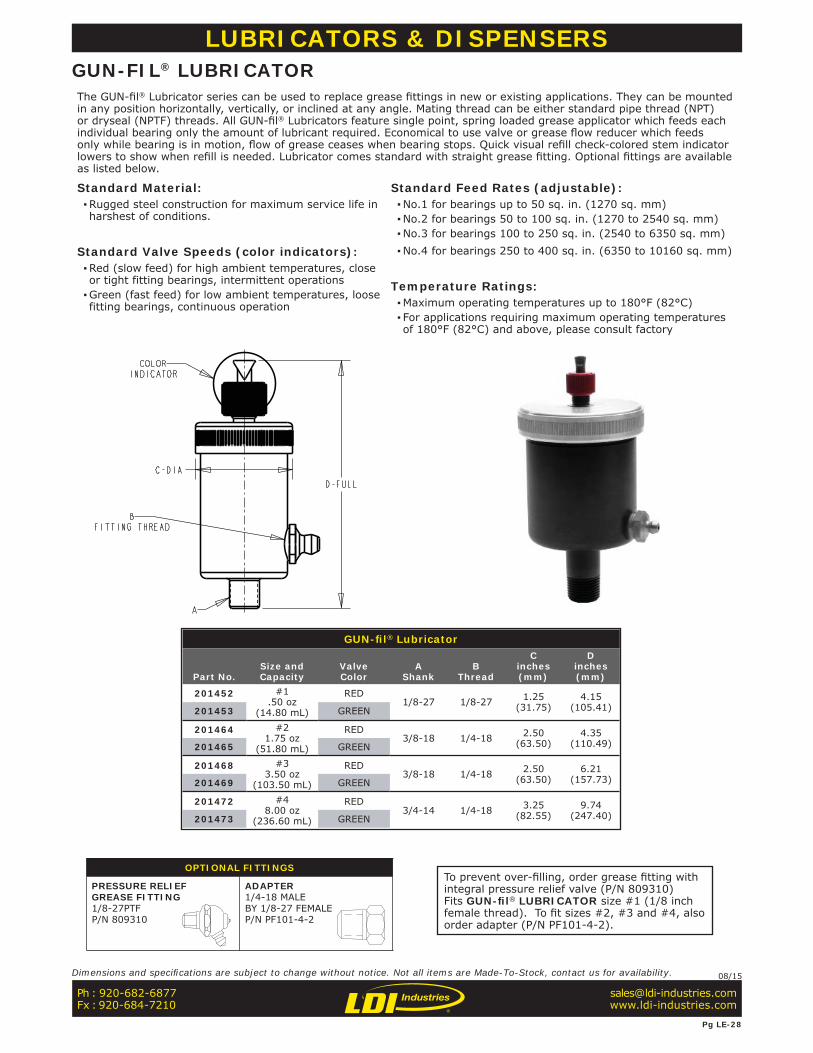
To prevent over-fi lling, order grease fi tting with integral pressure relief valve (P/N 809310) Fits GUN-fi l® LUBRICATOR size #1 (1/8 inch female thread). To fi t sizes #2, #3 and #4, also order adapter (P/N PF101-4-2).
GUN-fi l® Lubricator
Part No.Size andCapacity
ValveColor
AShank
BThread
Cinches(mm)
Dinches(mm)
201452 #1.50 oz
(14.80 mL)
RED1/8-27 1/8-27 1.25
(31.75)4.15
(105.41)201453 GREEN
201464 #21.75 oz
(51.80 mL)
RED3/8-18 1/4-18 2.50
(63.50)4.35
(110.49)201465 GREEN
201468 #33.50 oz
(103.50 mL)
RED3/8-18 1/4-18 2.50
(63.50)6.21
(157.73)201469 GREEN
201472 #48.00 oz
(236.60 mL)
RED3/4-14 1/4-18 3.25
(82.55)9.74
(247.40)201473 GREEN
LUBRICATORS & DISPENSERSGUN-FIL® LUBRICATORThe GUN-fi l® Lubricator series can be used to replace grease fi ttings in new or existing applications. They can be mounted in any position horizontally, vertically, or inclined at any angle. Mating thread can be either standard pipe thread (NPT) or dryseal (NPTF) threads. All GUN-fi l® Lubricators feature single point, spring loaded grease applicator which feeds each individual bearing only the amount of lubricant required. Economical to use valve or grease fl ow reducer which feeds only while bearing is in motion, fl ow of grease ceases when bearing stops. Quick visual refi ll check-colored stem indicator lowers to show when refi ll is needed. Lubricator comes standard with straight grease fi tting. Optional fi ttings are available as listed below.
Standard Material: ▪Rugged steel construction for maximum service life in harshest of conditions.
Standard Valve Speeds (color indicators): ▪Red (slow feed) for high ambient temperatures, close or tight fitting bearings, intermittent operations ▪Green (fast feed) for low ambient temperatures, loose fitting bearings, continuous operation
Standard Feed Rates (adjustable): ▪No.1 for bearings up to 50 sq. in. (1270 sq. mm) ▪No.2 for bearings 50 to 100 sq. in. (1270 to 2540 sq. mm) ▪No.3 for bearings 100 to 250 sq. in. (2540 to 6350 sq. mm) ▪No.4 for bearings 250 to 400 sq. in. (6350 to 10160 sq. mm)
Temperature Ratings: ▪Maximum operating temperatures up to 180°F (82°C) ▪ For applications requiring maximum operating temperatures of 180°F (82°C) and above, please consult factory
OPTIONAL FITTINGS
PRESSURE RELIEFGREASE FITTING1/8-27PTF P/N 809310
ADAPTER1/4-18 MALEBY 1/8-27 FEMALEP/N PF101-4-2
Ph : 920-682-6877Fx : 920-684-7210
Pg LE-28
Dimensions and specifi cations are subject to change without notice. Not all items are Made-To-Stock, contact us for availability. 08/15
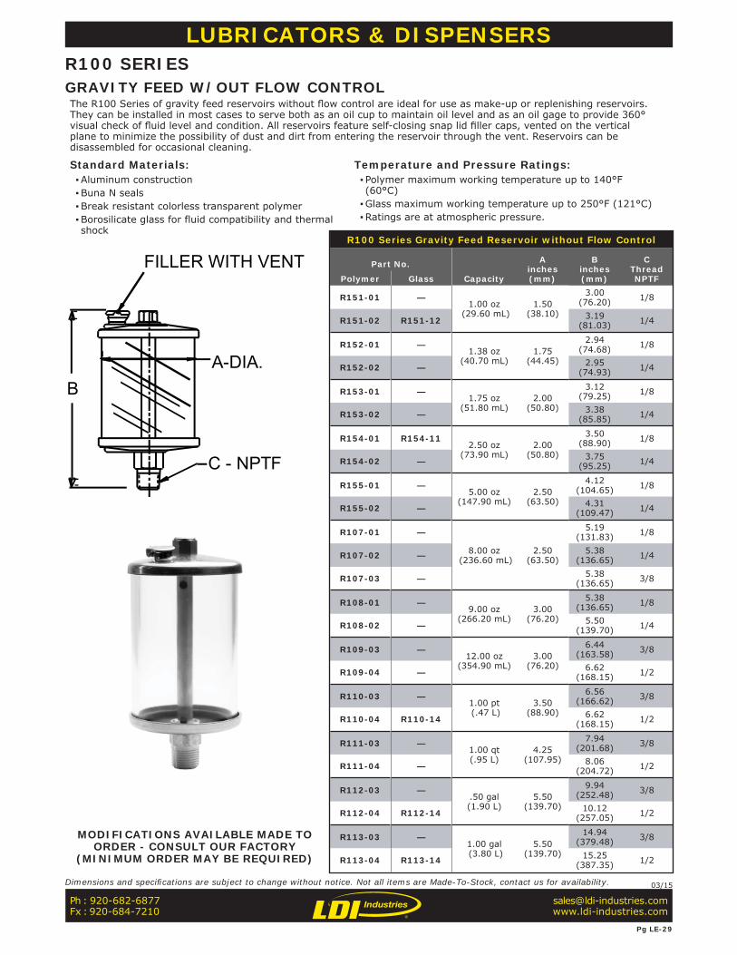
R100 Series Gravity Feed Reservoir without Flow Control
Part No.
Capacity
Ainches(mm)
Binches(mm)
CThreadNPTFPolymer Glass
R151-01 —1.00 oz
(29.60 mL)1.50
(38.10)
3.00(76.20) 1/8
R151-02 R151-12 3.19(81.03) 1/4
R152-01 —1.38 oz
(40.70 mL)1.75
(44.45)
2.94(74.68) 1/8
R152-02 — 2.95(74.93) 1/4
R153-01 —1.75 oz
(51.80 mL)2.00
(50.80)
3.12(79.25) 1/8
R153-02 — 3.38(85.85) 1/4
R154-01 R154-112.50 oz
(73.90 mL)2.00
(50.80)
3.50(88.90) 1/8
R154-02 — 3.75(95.25) 1/4
R155-01 —5.00 oz
(147.90 mL)2.50
(63.50)
4.12(104.65) 1/8
R155-02 — 4.31(109.47) 1/4
R107-01 —
8.00 oz (236.60 mL)
2.50(63.50)
5.19(131.83) 1/8
R107-02 — 5.38(136.65) 1/4
R107-03 — 5.38(136.65) 3/8
R108-01 —9.00 oz
(266.20 mL)3.00
(76.20)
5.38(136.65) 1/8
R108-02 — 5.50(139.70) 1/4
R109-03 —12.00 oz
(354.90 mL)3.00
(76.20)
6.44(163.58) 3/8
R109-04 — 6.62(168.15) 1/2
R110-03 —1.00 pt (.47 L)
3.50(88.90)
6.56(166.62) 3/8
R110-04 R110-14 6.62(168.15) 1/2
R111-03 —1.00 qt(.95 L)
4.25(107.95)
7.94(201.68) 3/8
R111-04 — 8.06(204.72) 1/2
R112-03 —.50 gal(1.90 L)
5.50(139.70)
9.94(252.48) 3/8
R112-04 R112-14 10.12(257.05) 1/2
R113-03 —1.00 gal (3.80 L)
5.50(139.70)
14.94(379.48) 3/8
R113-04 R113-14 15.25 (387.35) 1/2
C - NPTF
BA-DIA.
FILLER WITH VENT
LUBRICATORS & DISPENSERSR100 SERIES
The R100 Series of gravity feed reservoirs without fl ow control are ideal for use as make-up or replenishing reservoirs. They can be installed in most cases to serve both as an oil cup to maintain oil level and as an oil gage to provide 360° visual check of fl uid level and condition. All reservoirs feature self-closing snap lid fi ller caps, vented on the vertical plane to minimize the possibility of dust and dirt from entering the reservoir through the vent. Reservoirs can be disassembled for occasional cleaning.
Standard Materials: ▪Aluminum construction ▪Buna N seals ▪Break resistant colorless transparent polymer ▪Borosilicate glass for fluid compatibility and thermal shock
Temperature and Pressure Ratings: ▪ Polymer maximum working temperature up to 140°F (60°C) ▪Glass maximum working temperature up to 250°F (121°C) ▪Ratings are at atmospheric pressure.
MODIFICATIONS AVAILABLE MADE TO ORDER - CONSULT OUR FACTORY
(MINIMUM ORDER MAY BE REQUIRED)
Ph : 920-682-6877Fx : 920-684-7210
Pg LE-29
Dimensions and specifi cations are subject to change without notice. Not all items are Made-To-Stock, contact us for availability. 03/15
GRAVITY FEED W/OUT FLOW CONTROL
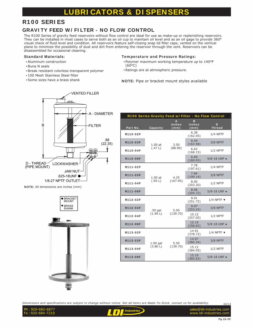
R100 Series Gravity Feed w/Filter - No Flow Control
Part No. Capacity
Ainches(mm)
Binches(mm)
DThread
R110-02F
1.00 pt(.47 L)
3.50(88.90)
6.38(162.05) 1/4 NPTF
R110-03F 6.44(163.58) 3/8 NPTF
R110-04F 6.62(168.15) 1/2 NPTF
R110-08F 6.69(169.93) 5/8-18 UNF ●
R111-02F
1.00 qt(.95 L)
4.25(107.95)
7.78(197.61) 1/4 NPTF
R111-03F 7.84(199.14) 3/8 NPTF
R111-04F 8.00(203.20) 1/2 NPTF
R111-08F 8.06(204.72) 5/8-18 UNF ●
R112-02F
.50 gal(1.90 L)
5.50(139.70)
9.91(251.72) 1/4 NPTF ▼
R112-03F 9.97(253.24) 3/8 NPTF
R112-04F 10.12(257.05) 1/2 NPTF
R112-08F 10.19(258.83) 5/8-18 UNF ●
R113-02F
1.00 gal(3.80 L)
5.50(139.70)
14.91(378.72) 1/4 NPTF ▼
R113-03F 14.97(380.24) 3/8 NPTF
R113-04F 15.12(384.05) 1/2 NPTF
R113-08F 15.19(385.83) 5/8-18 UNF ●
LOCKWASHER
JAM NUT
1/8-27 NPTF OUTLET
VENTED FILLER
FILTER
D - THREAD(PIPE MOUNT)
B
A - DIAMETER
.88(22.35)
.625-18UNF
LUBRICATORS & DISPENSERSR100 SERIES
The R100 Series of gravity feed reservoirs without fl ow control are ideal for use as make-up or replenishing reservoirs. They can be installed in most cases to serve both as an oil cup to maintain oil level and as an oil gage to provide 360° visual check of fl uid level and condition. All reservoirs feature self-closing snap lid fi ller caps, vented on the vertical plane to minimize the possibility of dust and dirt from entering the reservoir through the vent. Reservoirs can be disassembled for occasional cleaning.
Standard Materials: ▪Aluminum construction ▪Buna N seals ▪Break resistant colorless transparent polymer ▪100 Mesh Stainless Steel filter ▪Some sizes have a brass shank
Temperature and Pressure Ratings: ▪ Polymer maximum working temperature up to 140°F (60°C) ▪Ratings are at atmospheric pressure.
NOTE: Pipe or bracket mount styles available
BRACKET MOUNT
BRASS SHANK
Ph : 920-682-6877Fx : 920-684-7210
Pg LE-30
Dimensions and specifi cations are subject to change without notice. Not all items are Made-To-Stock, contact us for availability. 02/14
NOTE: All dimensions are inches (mm)
GRAVITY FEED W/FILTER - NO FLOW CONTROL
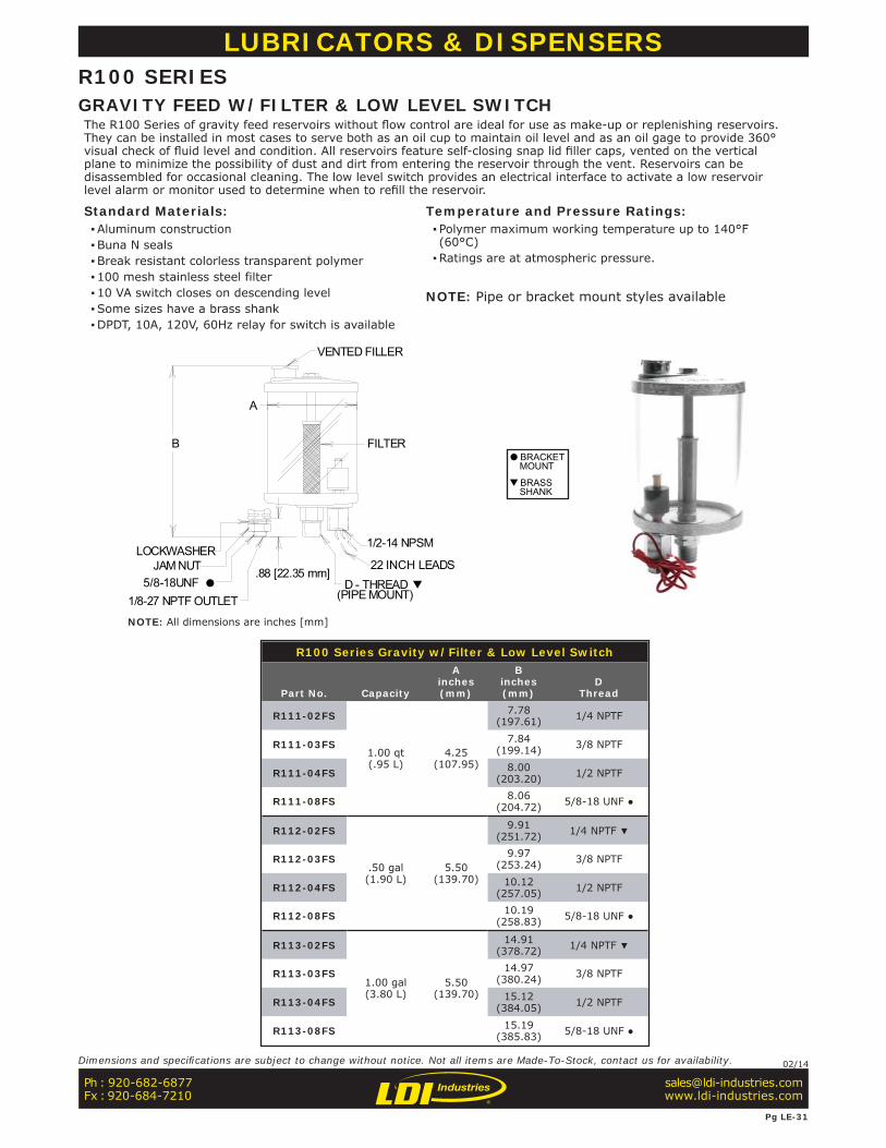
R100 Series Gravity w/Filter & Low Level Switch
Part No. Capacity
Ainches(mm)
Binches(mm)
DThread
R111-02FS
1.00 qt(.95 L)
4.25(107.95)
7.78(197.61) 1/4 NPTF
R111-03FS 7.84(199.14) 3/8 NPTF
R111-04FS 8.00(203.20) 1/2 NPTF
R111-08FS 8.06(204.72) 5/8-18 UNF ●
R112-02FS
.50 gal(1.90 L)
5.50(139.70)
9.91(251.72) 1/4 NPTF ▼
R112-03FS 9.97(253.24) 3/8 NPTF
R112-04FS 10.12(257.05) 1/2 NPTF
R112-08FS 10.19(258.83) 5/8-18 UNF ●
R113-02FS
1.00 gal(3.80 L)
5.50(139.70)
14.91(378.72) 1/4 NPTF ▼
R113-03FS 14.97(380.24) 3/8 NPTF
R113-04FS 15.12(384.05) 1/2 NPTF
R113-08FS 15.19(385.83) 5/8-18 UNF ●
VENTED FILLER
D - THREAD
FILTER
22 INCH LEADS
1/2-14 NPSM
B
A
(PIPE MOUNT)
LOCKWASHERJAM NUT
5/8-18UNF
1/8-27 NPTF OUTLET
.88 [22.35 mm]
LUBRICATORS & DISPENSERSR100 SERIES
The R100 Series of gravity feed reservoirs without fl ow control are ideal for use as make-up or replenishing reservoirs. They can be installed in most cases to serve both as an oil cup to maintain oil level and as an oil gage to provide 360° visual check of fl uid level and condition. All reservoirs feature self-closing snap lid fi ller caps, vented on the vertical plane to minimize the possibility of dust and dirt from entering the reservoir through the vent. Reservoirs can be disassembled for occasional cleaning. The low level switch provides an electrical interface to activate a low reservoir level alarm or monitor used to determine when to refi ll the reservoir.
Standard Materials: ▪Aluminum construction ▪Buna N seals ▪Break resistant colorless transparent polymer ▪100 mesh stainless steel filter ▪10 VA switch closes on descending level ▪Some sizes have a brass shank ▪DPDT, 10A, 120V, 60Hz relay for switch is available
Temperature and Pressure Ratings: ▪ Polymer maximum working temperature up to 140°F (60°C) ▪Ratings are at atmospheric pressure.
NOTE: Pipe or bracket mount styles available
BRACKET MOUNT
BRASS SHANK
Ph : 920-682-6877Fx : 920-684-7210
Pg LE-31
Dimensions and specifi cations are subject to change without notice. Not all items are Made-To-Stock, contact us for availability. 02/14
NOTE: All dimensions are inches [mm]
GRAVITY FEED W/FILTER & LOW LEVEL SWITCH
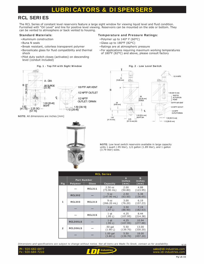
RCL Series
FigPart Number
Capacity
Ainches(mm)
Binches(mm)Polymer Glass
1
— RCL311 2.50 oz(73.90 mL)
2.00(50.80)
4.88(123.95)
RCL302 — 5 oz (147.90 mL)
2.50(63.50)
5.38(136.65)
RCL303 RCL313 9 oz (266.20 mL)
3.00(76.20)
6.19(157.23)
— — 1 pt (.47 L)
3.50(88.90)
7.19(182.63)
— RCL315 1 qt (.95 L)
4.25(107.95)
8.44(214.38)
2
RCL305LS — 1 qt (.95 L)
4.25(107.95)
10.94(277.88)
RCL306LS — .50 gal (1.90 L)
5.50(139.70)
13.00(330.20)
— — 1.00 gal (3.80 L)
5.50(139.70)
18.00(457.20)
1/2 NPTFOUTLET/DRAIN
1/8 PTF AIR VENT
1/2-14 NPS
OILLEVEL
1/2 NPTF OUTLET
CL
1.00 [25.4 mm] SIGHT DIA
ACTUATIONPOINT
1.50 [38.10 mm]B
1.12 [28.45 mm]
1.50 [38.10 mm]
A
.75
2.25 [57.15 mm] SQ
1.62
.88
.38
[19.05 mm]
[9.65 mm]
SURGE[22.35 mm]
SWITCH
[41.15 mm]
LCOIL
LEVEL
1.00 [25.40]
1/8 PTF AIR VENT
1/2 NPTF OUTLET
1/2 NPTFOUTLET / DRAIN
B
A - DIA
1.621.12 [28.45]2.25 SQ
.88 SURGE
1.50 [38.10]
[22.35]
SIGHT
[57.15][41.15]
.38
[9.6
5]
LUBRICATORS & DISPENSERSRCL SERIESThe RCL Series of constant level reservoirs feature a large sight window for viewing liquid level and fl uid condition. Furnished with “Oil Level” and line for positive level viewing. Reservoirs can be mounted on the side or bottom. They can be vented to atmosphere or back vented to housing.
Standard Materials: ▪Aluminum construction ▪Buna N seals ▪Break resistant, colorless transparent polymer ▪Borosilicate glass for fluid compatibility and thermal shock ▪ Pilot duty switch closes (activates) on descending level (conduit included)
Temperature and Pressure Ratings: ▪ Polymer up to 140° F (60°C) ▪Glass up to 180°F (82°C) ▪Ratings are at atmospheric pressure ▪ For applications requiring maximum working temperatures of 180°F (82°C) and above, please consult factory
Fig. 1 - Top Fill with Sight Window Fig. 2 - Low Level Switch
NOTE: Low level switch reservoirs available in large capacity units 1 quart (.95 liter), 1/2 gallon (1.89 liter), and 1 gallon (3.79 liter) sizes.
Ph : 920-682-6877Fx : 920-684-7210
Pg LE-32
Dimensions and specifi cations are subject to change without notice. Not all items are Made-To-Stock, contact us for availability. 4/16
NOTE: All dimensions are inches [mm]
FILLER WITHVENT
DC
B
A
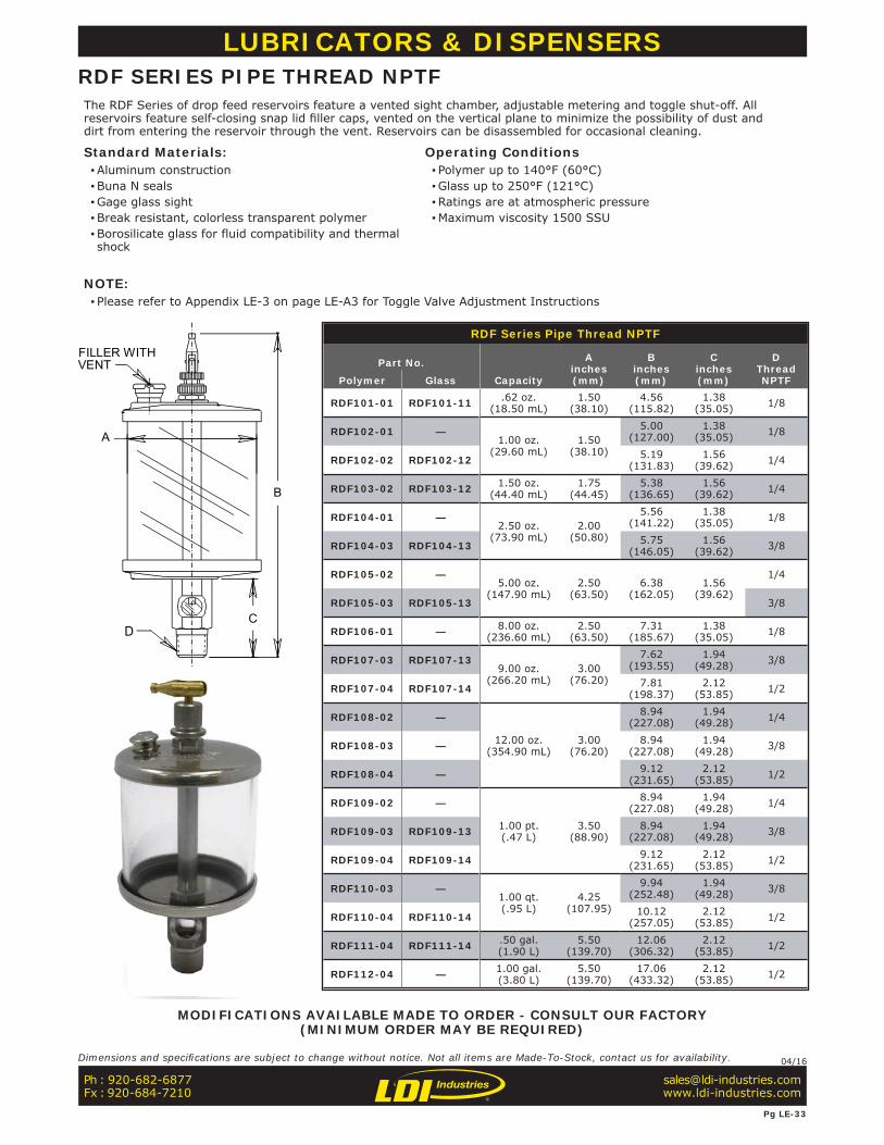
RDF Series Pipe Thread NPTF
Part No.
Capacity
Ainches(mm)
Binches(mm)
Cinches(mm)
DThreadNPTFPolymer Glass
RDF101-01 RDF101-11 .62 oz.(18.50 mL)
1.50(38.10)
4.56(115.82)
1.38(35.05) 1/8
RDF102-01 —1.00 oz.
(29.60 mL)1.50
(38.10)
5.00(127.00)
1.38(35.05) 1/8
RDF102-02 RDF102-12 5.19(131.83)
1.56(39.62) 1/4
RDF103-02 RDF103-12 1.50 oz. (44.40 mL)
1.75 (44.45)
5.38(136.65)
1.56(39.62) 1/4
RDF104-01 —2.50 oz.
(73.90 mL)2.00
(50.80)
5.56(141.22)
1.38(35.05) 1/8
RDF104-03 RDF104-13 5.75(146.05)
1.56(39.62) 3/8
RDF105-02 —5.00 oz.
(147.90 mL)2.50
(63.50)6.38
(162.05)1.56
(39.62)
1/4
RDF105-03 RDF105-13 3/8
RDF106-01 — 8.00 oz.(236.60 mL)
2.50(63.50)
7.31(185.67)
1.38(35.05) 1/8
RDF107-03 RDF107-139.00 oz.
(266.20 mL)3.00
(76.20)
7.62(193.55)
1.94(49.28) 3/8
RDF107-04 RDF107-14 7.81(198.37)
2.12(53.85) 1/2
RDF108-02 —
12.00 oz.(354.90 mL)
3.00(76.20)
8.94(227.08)
1.94(49.28) 1/4
RDF108-03 — 8.94(227.08)
1.94(49.28) 3/8
RDF108-04 — 9.12(231.65)
2.12(53.85) 1/2
RDF109-02 —
1.00 pt.(.47 L)
3.50(88.90)
8.94(227.08)
1.94(49.28) 1/4
RDF109-03 RDF109-13 8.94(227.08)
1.94(49.28) 3/8
RDF109-04 RDF109-14 9.12(231.65)
2.12(53.85) 1/2
RDF110-03 —1.00 qt.(.95 L)
4.25(107.95)
9.94(252.48)
1.94(49.28) 3/8
RDF110-04 RDF110-14 10.12(257.05)
2.12(53.85) 1/2
RDF111-04 RDF111-14 .50 gal.(1.90 L)
5.50(139.70)
12.06(306.32)
2.12(53.85) 1/2
RDF112-04 — 1.00 gal.(3.80 L)
5.50(139.70)
17.06(433.32)
2.12(53.85) 1/2
LUBRICATORS & DISPENSERSRDF SERIES PIPE THREAD NPTFThe RDF Series of drop feed reservoirs feature a vented sight chamber, adjustable metering and toggle shut-off. All reservoirs feature self-closing snap lid fi ller caps, vented on the vertical plane to minimize the possibility of dust and dirt from entering the reservoir through the vent. Reservoirs can be disassembled for occasional cleaning.
Standard Materials: ▪Aluminum construction ▪Buna N seals ▪Gage glass sight ▪Break resistant, colorless transparent polymer ▪Borosilicate glass for fluid compatibility and thermal shock
Operating Conditions ▪ Polymer up to 140°F (60°C) ▪Glass up to 250°F (121°C) ▪Ratings are at atmospheric pressure ▪Maximum viscosity 1500 SSU
NOTE: ▪ Please refer to Appendix LE-3 on page LE-A3 for Toggle Valve Adjustment Instructions
MODIFICATIONS AVAILABLE MADE TO ORDER - CONSULT OUR FACTORY(MINIMUM ORDER MAY BE REQUIRED)
Ph : 920-682-6877Fx : 920-684-7210
Pg LE-33
Dimensions and specifi cations are subject to change without notice. Not all items are Made-To-Stock, contact us for availability. 04/16
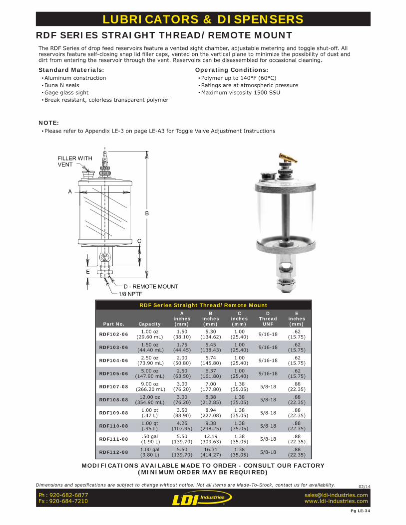
RDF Series Straight Thread/Remote Mount
Part No. Capacity
Ainches(mm)
Binches(mm)
Cinches(mm)
DThread
UNF
Einches(mm)
RDF102-06 1.00 oz(29.60 mL)
1.50(38.10)
5.30(134.62)
1.00(25.40) 9/16-18 .62
(15.75)
RDF103-06 1.50 oz (44.40 mL)
1.75(44.45)
5.45(138.43)
1.00(25.40) 9/16-18 .62
(15.75)
RDF104-06 2.50 oz (73.90 mL)
2.00(50.80)
5.74(145.80)
1.00(25.40) 9/16-18 .62
(15.75)
RDF105-06 5.00 oz (147.90 mL)
2.50(63.50)
6.37(161.80)
1.00(25.40) 9/16-18 .62
(15.75)
RDF107-08 9.00 oz (266.20 mL)
3.00(76.20)
7.00(177.80)
1.38(35.05) 5/8-18 .88
(22.35)
RDF108-08 12.00 oz(354.90 mL)
3.00(76.20)
8.38(212.85)
1.38(35.05) 5/8-18 .88
(22.35)
RDF109-08 1.00 pt(.47 L)
3.50(88.90)
8.94(227.08)
1.38(35.05) 5/8-18 .88
(22.35)
RDF110-08 1.00 qt(.95 L)
4.25(107.95)
9.38(238.25)
1.38(35.05) 5/8-18 .88
(22.35)
RDF111-08 .50 gal (1.90 L)
5.50(139.70)
12.19(309.63)
1.38(35.05) 5/8-18 .88
(22.35)
RDF112-08 1.00 gal(3.80 L)
5.50(139.70)
16.31(414.27)
1.38(35.05) 5/8-18 .88
(22.35)
D - REMOTE MOUNT1/8 NPTF
FILLER WITHVENT
B
A
E
C
LUBRICATORS & DISPENSERSRDF SERIES STRAIGHT THREAD/REMOTE MOUNTThe RDF Series of drop feed reservoirs feature a vented sight chamber, adjustable metering and toggle shut-off. All reservoirs feature self-closing snap lid fi ller caps, vented on the vertical plane to minimize the possibility of dust and dirt from entering the reservoir through the vent. Reservoirs can be disassembled for occasional cleaning.
Standard Materials: ▪Aluminum construction ▪Buna N seals ▪Gage glass sight ▪Break resistant, colorless transparent polymer
Operating Conditions: ▪ Polymer up to 140°F (60°C) ▪Ratings are at atmospheric pressure ▪Maximum viscosity 1500 SSU
NOTE: ▪ Please refer to Appendix LE-3 on page LE-A3 for Toggle Valve Adjustment Instructions
MODIFICATIONS AVAILABLE MADE TO ORDER - CONSULT OUR FACTORY(MINIMUM ORDER MAY BE REQUIRED)
Ph : 920-682-6877Fx : 920-684-7210
Pg LE-34
Dimensions and specifi cations are subject to change without notice. Not all items are Made-To-Stock, contact us for availability. 02/14

RDM Series
Part No. Capacity
Ainches(mm)
Binches(mm)
RDM101 9.00 oz(266.20 mL)
3.00(76.20)
8.50(215.90)
RDM102 12.00 oz(354.90 mL)
3.00(76.20)
9.50(241.30)
RDM103 1.00 pt(.47 L)
3.50(88.90)
9.50(241.30)
RDM104 1.00 qt(.95 L)
4.25(107.95)
10.69(271.53)
RDM105 .50 gal(1.90 L)
5.50(139.70)
12.75(323.85)
RDM106 1.00 gal(3.80 L)
5.50(139.70)
17.75(450.85)
FILLER WITHVENT
5/8-18UNFMOUNT
B
1/4 TUBE
.75
A - DIA
3.81
1.50
3.00
L1
L2
[96.77]
[33.27]
[19.05] [38.10]
[41.15] [25.40]
[76.20]1.31
1.001.62
LUBRICATORS & DISPENSERSRDM SERIESThe RDM Series of multiple feed, large capacity reservoirs with central mounting shank provide for controlled lubrication for up to 30 points from one location. Manually operated toggle lever at the top of reservoir controls on/off full fl ow of oil to valves. Valve drip feed rate is individually set at each valve. Large reservoir provides 360° viewing at a glance. Vent on the vertical plane so dust and dirt cannot enter the reservoir. Exclusive patented compact manifold design allows for easy removal of any of the valves. Units with odd number of feeds will be furnished with greater number of feeds to the right side unless otherwise specifi ed.
Standard Materials: ▪Aluminum construction ▪Buna N seals ▪Break resistant, colorless transparent polymer
Temperature and Pressure Ratings: ▪Maximum working temperature up to 140°F (60°C) ▪Rating is at atmospheric pressure
NOTE: ▪ Please refer to Appendix LE-3 on page LE-A3 for Toggle Valve Adjustment Instructions ▪ For outdoor or damp applications, please specify Anodized. ▪ For replacement feeds, please order part number 352890
Feeds
-02inches(mm)
-03inches(mm)
-04inches(mm)
-05inches(mm)
-06inches(mm)
-10inches(mm)
-20inches(mm)
-30inches(mm)
L1 2.19(55.62)
2.94(74.68)
2.94(74.68)
3.69(93.73)
3.69(93.73)
5.19(131.83)
8.94(227.08)
12.69(322.33)
L2 4.38(111.25)
5.12(130.05)
5.88(149.35)
6.62(168.15)
7.38(187.45)
10.38(263.65)
17.88(454.15)
25.38(644.65)
MODIFICATIONS AVAILABLE MADE TO ORDER - CONSULT OUR FACTORY(MINIMUM ORDER MAY BE REQUIRED)
ORDERING OPTIONS:
OrderSuffi x Feeds
-02-30
Specify 02 through 30 feeds.(2 feeds are standard)
HOW TO ORDEREXAMPLE:RDM103-02 2 feeds (standard)
Series RDM103 - 1 pint (.47 liter)capacity reservoir
Ph : 920-682-6877Fx : 920-684-7210
Pg LE-35
Dimensions and specifi cations are subject to change without notice. Not all items are Made-To-Stock, contact us for availability. 04/16
NOTE: All dimensions are inches [mm]
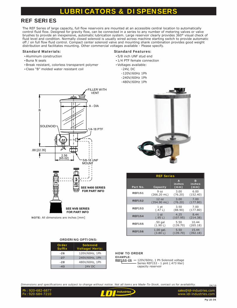
REF Series
Part No. Capacity
Ainches(mm)
Binches(mm)
REF151 9 oz(266.20 mL)
3.00(76.20)
6.00(152.40)
REF152 12 oz(354.90 mL)
3.00(76.20)
7.00(177.80)
REF153 1 pt(.47 L)
3.50(88.90)
7.00(177.80)
REF154 1 qt(.95 L)
4.25(107.95)
8.44(214.38)
REF155 .50 gal(1.90 L)
5.50(139.70)
10.44(265.18)
REF156 1.00 gal.(3.80 L)
5.50(139.70)
15.44(392.18)
FILLER WITH VENT
5/8-18 UNFMOUNT
1/4-18 PTFSOLENOID
BA - DIA
.88 [22.35]
SEE N400 SERIESFOR PART INFO
[65.02]2.56
SEE NVB SERIESFOR PART INFO
LUBRICATORS & DISPENSERSREF SERIESThe REF Series of large capacity, full fl ow reservoirs are mounted at an accessible central location to automatically control fl uid fl ow. Designed for gravity fl ow, can be connected in a series to any number of metering valves or valve brushes to provide an inexpensive, automatic lubrication system. Large reservoir clearly provides 360° visual check of fl uid level and condition. Normally closed solenoid is usually wired across machine starting switch to provide automatic off / on full fl ow fl uid control. Compact center solenoid valve and mounting shank combination provides good weight distribution and facilitates mounting. Other commercial voltages available - Please specify.
Standard Materials: ▪Aluminum construction ▪Buna N seals ▪Break resistant, colorless transparent polymer ▪Class “B” molded water resistant coil
Standard Features: ▪5/8 inch UNF stud end ▪1/4 PTF female connection ▪Voltages available:
▫24V, DC ▫120V/60Hz 1Ph ▫240V/60Hz 1Ph ▫480V/60Hz 1Ph
ORDERING OPTIONS:
OrderSuffi x
SolenoidVoltage/Hertz:
-26 120V/60Hz, 1Ph-27 240V/60Hz, 1Ph-28 480V/60Hz, 1Ph-43 24V DC
HOW TO ORDEREXAMPLE:REF153-26 120V/60Hz, 1 Ph Solenoid voltage
Series REF153 - 1 pint (.473 liter)capacity reservoir
Ph : 920-682-6877Fx : 920-684-7210
Pg LE-36
Dimensions and specifi cations are subject to change without notice. Not all items are Made-To-Stock, contact us for availability. 04/16
NOTE: All dimensions are inches [mm]
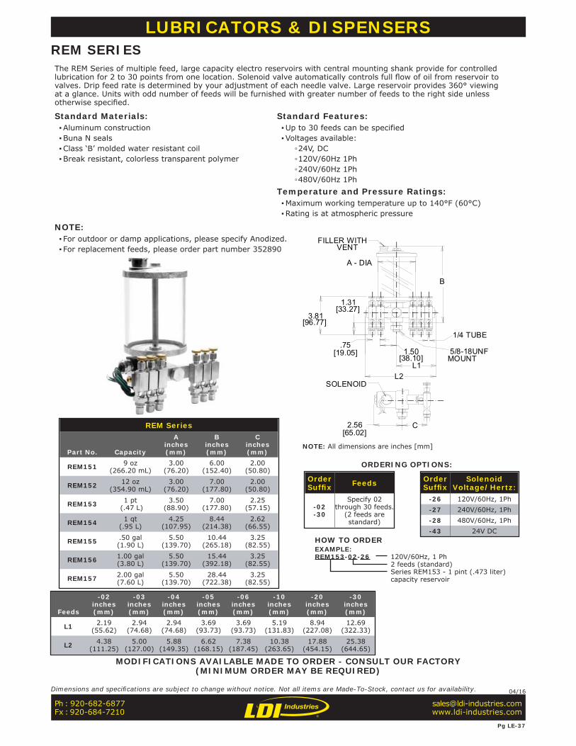
FILLER WITHVENT
5/8-18UNFMOUNT
SOLENOID
3.81
1.31
A - DIA
C
1.50
2.56
B
1/4 TUBE.75
[96.77]
[33.27]
[19.05][38.10]
L1L2
[65.02]REM Series
Part No. Capacity
Ainches(mm)
Binches(mm)
Cinches(mm)
REM151 9 oz(266.20 mL)
3.00(76.20)
6.00(152.40)
2.00(50.80)
REM152 12 oz(354.90 mL)
3.00(76.20)
7.00(177.80)
2.00(50.80)
REM153 1 pt (.47 L)
3.50(88.90)
7.00(177.80)
2.25(57.15)
REM154 1 qt(.95 L)
4.25(107.95)
8.44(214.38)
2.62(66.55)
REM155 .50 gal(1.90 L)
5.50(139.70)
10.44(265.18)
3.25(82.55)
REM156 1.00 gal(3.80 L)
5.50(139.70)
15.44(392.18)
3.25(82.55)
REM157 2.00 gal(7.60 L)
5.50(139.70)
28.44(722.38)
3.25(82.55)
Feeds
-02inches(mm)
-03inches(mm)
-04inches(mm)
-05inches(mm)
-06inches(mm)
-10inches(mm)
-20inches(mm)
-30inches(mm)
L1 2.19(55.62)
2.94(74.68)
2.94(74.68)
3.69(93.73)
3.69(93.73)
5.19(131.83)
8.94(227.08)
12.69(322.33)
L2 4.38(111.25)
5.00(127.00)
5.88(149.35)
6.62(168.15)
7.38(187.45)
10.38(263.65)
17.88(454.15)
25.38 (644.65)
LUBRICATORS & DISPENSERSREM SERIESThe REM Series of multiple feed, large capacity electro reservoirs with central mounting shank provide for controlled lubrication for 2 to 30 points from one location. Solenoid valve automatically controls full fl ow of oil from reservoir to valves. Drip feed rate is determined by your adjustment of each needle valve. Large reservoir provides 360° viewing at a glance. Units with odd number of feeds will be furnished with greater number of feeds to the right side unless otherwise specifi ed.
Standard Materials: ▪Aluminum construction ▪Buna N seals ▪Class ‘B’ molded water resistant coil ▪Break resistant, colorless transparent polymer
Standard Features: ▪Up to 30 feeds can be specified ▪Voltages available:
▫24V, DC ▫120V/60Hz 1Ph ▫240V/60Hz 1Ph ▫480V/60Hz 1Ph
Temperature and Pressure Ratings: ▪Maximum working temperature up to 140°F (60°C) ▪Rating is at atmospheric pressure
NOTE: ▪ For outdoor or damp applications, please specify Anodized. ▪ For replacement feeds, please order part number 352890
MODIFICATIONS AVAILABLE MADE TO ORDER - CONSULT OUR FACTORY(MINIMUM ORDER MAY BE REQUIRED)
ORDERING OPTIONS:
OrderSuffi x Feeds
-02-30
Specify 02 through 30 feeds.
(2 feeds are standard)
OrderSuffi x
SolenoidVoltage/Hertz:
-26 120V/60Hz, 1Ph-27 240V/60Hz, 1Ph-28 480V/60Hz, 1Ph-43 24V DC
HOW TO ORDEREXAMPLE:REM153-02-26 120V/60Hz, 1 Ph
2 feeds (standard)Series REM153 - 1 pint (.473 liter)capacity reservoir
Ph : 920-682-6877Fx : 920-684-7210
Pg LE-37
Dimensions and specifi cations are subject to change without notice. Not all items are Made-To-Stock, contact us for availability. 04/16
NOTE: All dimensions are inches [mm]
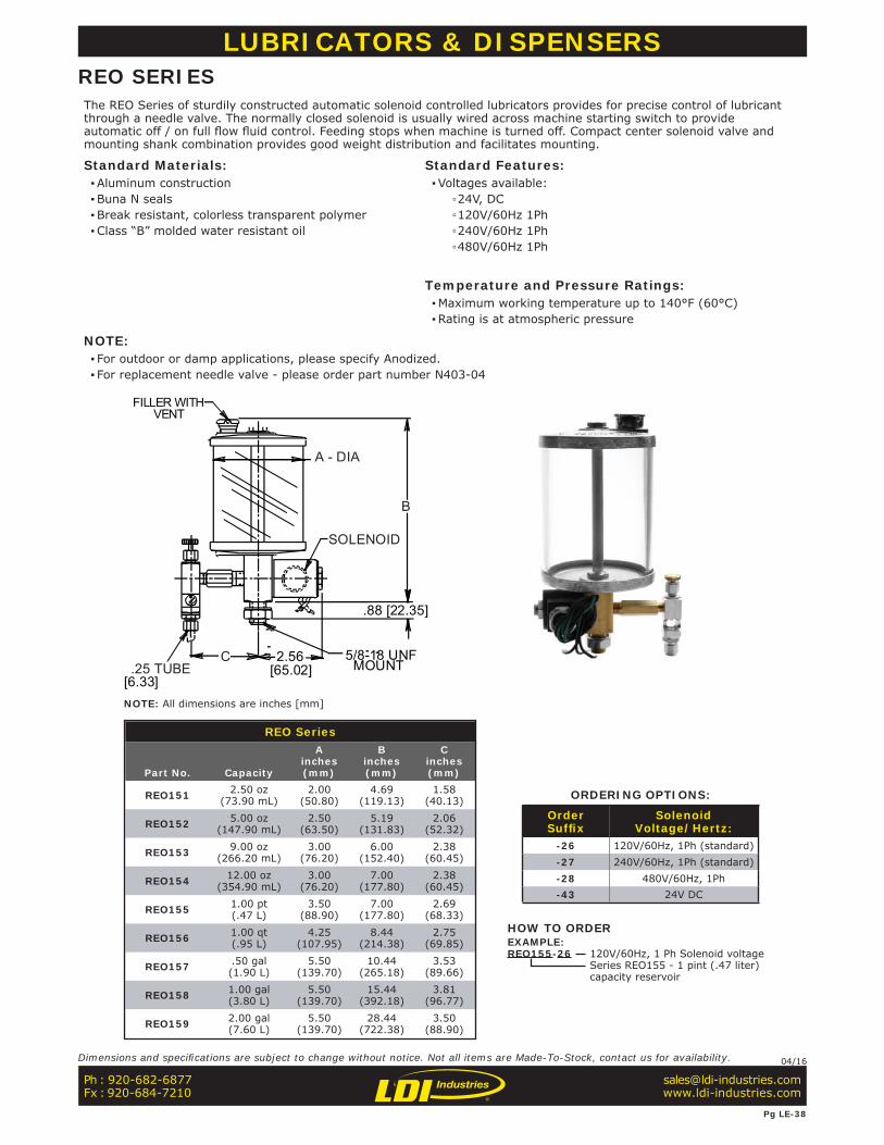
REO Series
Part No. Capacity
Ainches(mm)
Binches(mm)
Cinches(mm)
REO151 2.50 oz(73.90 mL)
2.00(50.80)
4.69(119.13)
1.58(40.13)
REO152 5.00 oz(147.90 mL)
2.50(63.50)
5.19(131.83)
2.06(52.32)
REO153 9.00 oz(266.20 mL)
3.00(76.20)
6.00(152.40)
2.38(60.45)
REO154 12.00 oz(354.90 mL)
3.00(76.20)
7.00(177.80)
2.38(60.45)
REO155 1.00 pt(.47 L)
3.50(88.90)
7.00(177.80)
2.69(68.33)
REO156 1.00 qt(.95 L)
4.25(107.95)
8.44(214.38)
2.75(69.85)
REO157 .50 gal(1.90 L)
5.50(139.70)
10.44(265.18)
3.53(89.66)
REO158 1.00 gal(3.80 L)
5.50(139.70)
15.44(392.18)
3.81(96.77)
REO159 2.00 gal(7.60 L)
5.50(139.70)
28.44(722.38)
3.50(88.90)
SOLENOID
.25 TUBE
A - DIA
B
C 2.56[65.02]
.88 [22.35]
MOUNT[6.33]
5/8-18 UNF
FILLER WITHVENT
LUBRICATORS & DISPENSERSREO SERIESThe REO Series of sturdily constructed automatic solenoid controlled lubricators provides for precise control of lubricant through a needle valve. The normally closed solenoid is usually wired across machine starting switch to provide automatic off / on full fl ow fl uid control. Feeding stops when machine is turned off. Compact center solenoid valve and mounting shank combination provides good weight distribution and facilitates mounting.
Standard Materials: ▪Aluminum construction ▪Buna N seals ▪Break resistant, colorless transparent polymer ▪Class “B” molded water resistant oil
Standard Features: ▪Voltages available:
▫24V, DC ▫120V/60Hz 1Ph ▫240V/60Hz 1Ph ▫480V/60Hz 1Ph
Temperature and Pressure Ratings: ▪Maximum working temperature up to 140°F (60°C) ▪Rating is at atmospheric pressure
NOTE: ▪ For outdoor or damp applications, please specify Anodized. ▪ For replacement needle valve - please order part number N403-04
ORDERING OPTIONS:
OrderSuffi x
SolenoidVoltage/Hertz:
-26 120V/60Hz, 1Ph (standard)-27 240V/60Hz, 1Ph (standard)-28 480V/60Hz, 1Ph-43 24V DC
HOW TO ORDEREXAMPLE:REO155-26 120V/60Hz, 1 Ph Solenoid voltage
Series REO155 - 1 pint (.47 liter)capacity reservoir
Ph : 920-682-6877Fx : 920-684-7210
Pg LE-38
Dimensions and specifi cations are subject to change without notice. Not all items are Made-To-Stock, contact us for availability. 04/16
NOTE: All dimensions are inches [mm]
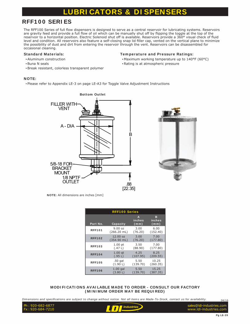
FILLER WITHVENT
5/8-18 FORBRACKETMOUNT
1/8 NPTFOUTLET
B
A - DIA
.88[22.35]
RFF100 Series
Part No. Capacity
Ainches(mm)
Binches(mm)
RFF101 9.00 oz(266.20 mL)
3.00(76.20)
6.00(152.40)
RFF102 12.00 oz(354.90 mL)
3.00(76.20)
7.00(177.80)
RFF103 1.00 pt(.47 L)
3.50(88.90)
7.00(177.80)
RFF104 1.00 qt(.95 L)
4.25(107.95)
8.25(209.55)
RFF105 .50 gal(1.90 L)
5.50(139.70)
10.25(260.35)
RFF106 1.00 gal(3.80 L)
5.50(139.70)
15.25(387.35)
LUBRICATORS & DISPENSERSRFF100 SERIESThe RFF100 Series of full fl ow dispensers is designed to serve as a central reservoir for lubricating systems. Reservoirs are gravity feed and provide a full fl ow of oil which can be manually shut off by fl ipping the toggle at the top of the reservoir to a horizontal position. Electric Solenoid shut off is available. Reservoirs provide a 360° visual check of fl uid level and condition. All reservoirs also feature a self-closing snap lid fi ller cap, vented on the vertical plane to minimize the possibility of dust and dirt from entering the reservoir through the vent. Reservoirs can be disassembled for occasional cleaning.
Standard Materials: ▪Aluminum construction ▪Buna N seals ▪Break resistant, colorless transparent polymer
Temperature and Pressure Ratings: ▪Maximum working temperature up to 140°F (60°C) ▪Rating is at atmospheric pressure
NOTE: ▪ Please refer to Appendix LE-3 on page LE-A3 for Toggle Valve Adjustment Instructions
MODIFICATIONS AVAILABLE MADE TO ORDER - CONSULT OUR FACTORY(MINIMUM ORDER MAY BE REQUIRED)
Bottom Outlet
Ph : 920-682-6877Fx : 920-684-7210
Pg LE-39
Dimensions and specifi cations are subject to change without notice. Not all items are Made-To-Stock, contact us for availability. 04/16
NOTE: All dimensions are inches [mm]
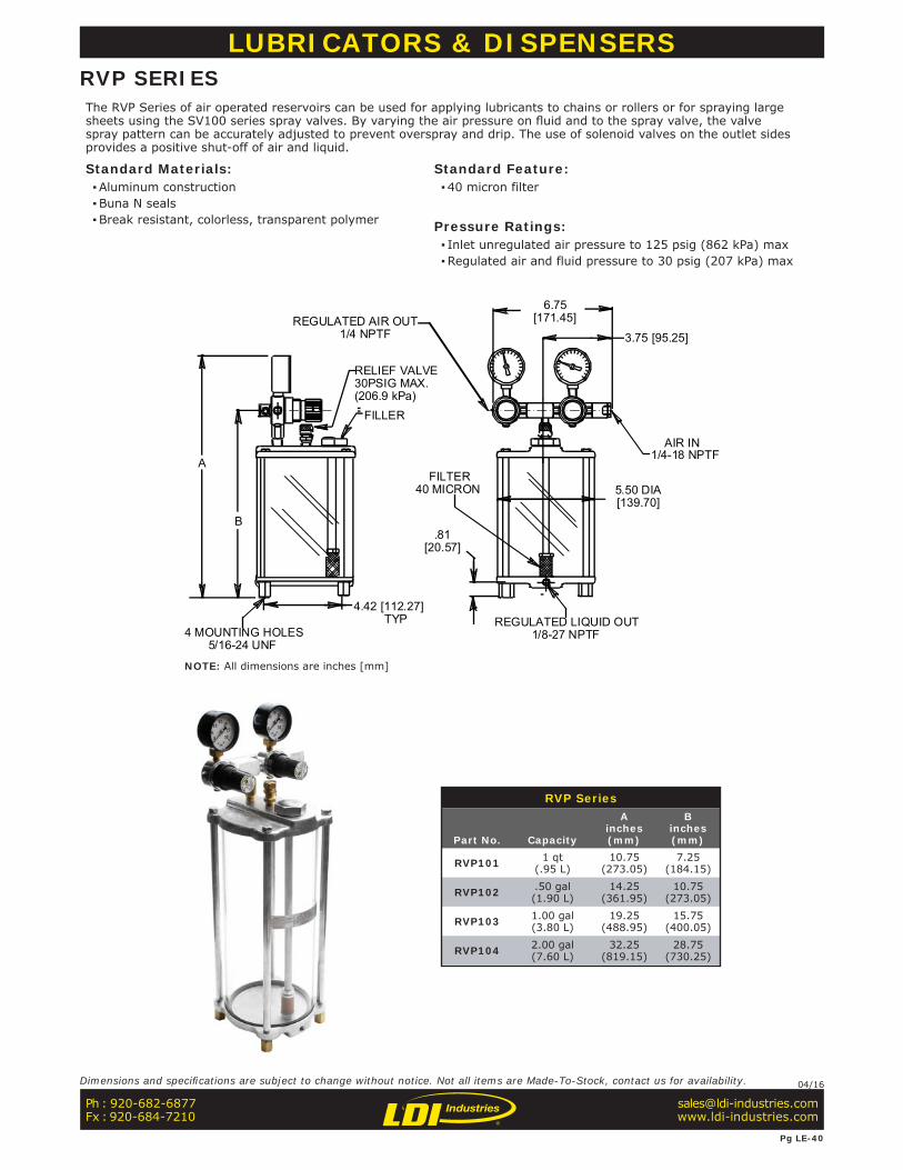
RVP Series
Part No. Capacity
Ainches(mm)
Binches(mm)
RVP101 1 qt(.95 L)
10.75(273.05)
7.25(184.15)
RVP102 .50 gal(1.90 L)
14.25(361.95)
10.75(273.05)
RVP103 1.00 gal(3.80 L)
19.25(488.95)
15.75(400.05)
RVP104 2.00 gal(7.60 L)
32.25(819.15)
28.75(730.25)
A
B
RELIEF VALVE30PSIG MAX.(206.9 kPa)
FILLER
REGULATED AIR OUT 1/4 NPTF
6.75 [171.45]
3.75 [95.25]
AIR IN1/4-18 NPTF
5.50 DIA[139.70]
FILTER40 MICRON
.81[20.57]
REGULATED LIQUID OUT 1/8-27 NPTF
4.42 [112.27] TYP
4 MOUNTING HOLES 5/16-24 UNF
LUBRICATORS & DISPENSERSRVP SERIESThe RVP Series of air operated reservoirs can be used for applying lubricants to chains or rollers or for spraying large sheets using the SV100 series spray valves. By varying the air pressure on fl uid and to the spray valve, the valve spray pattern can be accurately adjusted to prevent overspray and drip. The use of solenoid valves on the outlet sides provides a positive shut-off of air and liquid.
Standard Materials: ▪Aluminum construction ▪Buna N seals ▪Break resistant, colorless, transparent polymer
Standard Feature: ▪40 micron filter
Pressure Ratings: ▪ Inlet unregulated air pressure to 125 psig (862 kPa) max ▪Regulated air and fluid pressure to 30 psig (207 kPa) max
Ph : 920-682-6877Fx : 920-684-7210
Pg LE-40
Dimensions and specifi cations are subject to change without notice. Not all items are Made-To-Stock, contact us for availability. 04/16
NOTE: All dimensions are inches [mm]
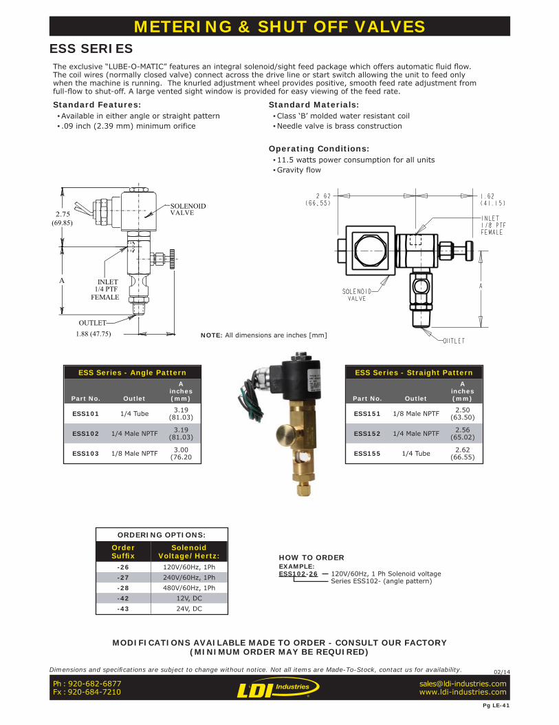
SOLENOIDVALVE
OUTLET
INLET1/4 PTF
FEMALE
2.75
A
1.88 (47.75)
(69.85)
ESS Series - Angle Pattern
Part No. Outlet
Ainches(mm)
ESS101 1/4 Tube 3.19 (81.03)
ESS102 1/4 Male NPTF 3.19 (81.03)
ESS103 1/8 Male NPTF 3.00 (76.20
ESS Series - Straight Pattern
Part No. Outlet
Ainches(mm)
ESS151 1/8 Male NPTF 2.50 (63.50)
ESS152 1/4 Male NPTF 2.56 (65.02)
ESS155 1/4 Tube 2.62 (66.55)
METERING & SHUT OFF VALVESESS SERIESThe exclusive “LUBE-O-MATIC” features an integral solenoid/sight feed package which offers automatic fl uid fl ow. The coil wires (normally closed valve) connect across the drive line or start switch allowing the unit to feed only when the machine is running. The knurled adjustment wheel provides positive, smooth feed rate adjustment from full-fl ow to shut-off. A large vented sight window is provided for easy viewing of the feed rate.
Standard Features: ▪Available in either angle or straight pattern ▪ .09 inch (2.39 mm) minimum orifice
Standard Materials: ▪Class ‘B’ molded water resistant coil ▪Needle valve is brass construction
Operating Conditions: ▪11.5 watts power consumption for all units ▪Gravity flow
ORDERING OPTIONS:
OrderSuffi x
SolenoidVoltage/Hertz:
-26 120V/60Hz, 1Ph-27 240V/60Hz, 1Ph-28 480V/60Hz, 1Ph-42 12V, DC-43 24V, DC
HOW TO ORDEREXAMPLE:ESS102-26 120V/60Hz, 1 Ph Solenoid voltage
Series ESS102- (angle pattern)
MODIFICATIONS AVAILABLE MADE TO ORDER - CONSULT OUR FACTORY(MINIMUM ORDER MAY BE REQUIRED)
NOTE: All dimensions are inches [mm]
Ph : 920-682-6877Fx : 920-684-7210
Pg LE-41
Dimensions and specifi cations are subject to change without notice. Not all items are Made-To-Stock, contact us for availability. 02/14
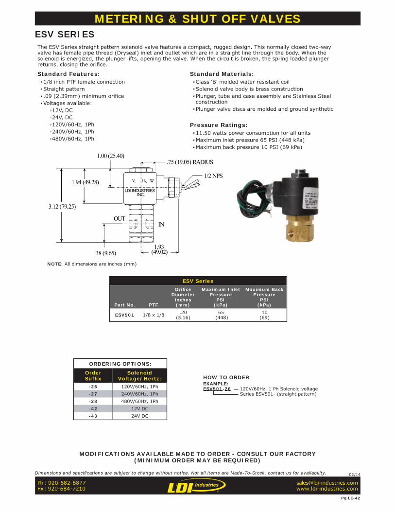
METERING & SHUT OFF VALVESESV SERIESThe ESV Series straight pattern solenoid valve features a compact, rugged design. This normally closed two-way valve has female pipe thread (Dryseal) inlet and outlet which are in a straight line through the body. When the solenoid is energized, the plunger lifts, opening the valve. When the circuit is broken, the spring loaded plunger returns, closing the orifi ce.
Standard Features: ▪1/8 inch PTF female connection ▪Straight pattern ▪ .09 (2.39mm) minimum orifice ▪Voltages available:
▫12V, DC ▫24V, DC ▫120V/60Hz, 1Ph ▫240V/60Hz, 1Ph ▫480V/60Hz, 1Ph
Standard Materials: ▪Class ‘B’ molded water resistant coil ▪Solenoid valve body is brass construction ▪ Plunger, tube and case assembly are Stainless Steel construction ▪ Plunger valve discs are molded and ground synthetic
Pressure Ratings: ▪11.50 watts power consumption for all units ▪Maximum inlet pressure 65 PSI (448 kPa) ▪Maximum back pressure 10 PSI (69 kPa)
V, Hz, W
LDI INDUSTRIESINC.
3.12 (79.25)
1.94 (49.28)
.38 (9.65)
OUTIN
1/2 NPS
.75 (19.05) RADIUS1.00 (25.40)
(49.02)1.93
ORDERING OPTIONS:
OrderSuffi x
SolenoidVoltage/Hertz:
-26 120V/60Hz, 1Ph-27 240V/60Hz, 1Ph-28 480V/60Hz, 1Ph-42 12V DC-43 24V DC
ESV Series
Part No. PTF
Orifi ceDiameter
inches(mm)
Maximum InletPressure
PSI(kPa)
Maximum BackPressure
PSI(kPa)
ESV501 1/8 x 1/8 .20(5.16)
65 (448)
10(69)
HOW TO ORDEREXAMPLE:ESV501-26 120V/60Hz, 1 Ph Solenoid voltage
Series ESV501- (straight pattern)
MODIFICATIONS AVAILABLE MADE TO ORDER - CONSULT OUR FACTORY(MINIMUM ORDER MAY BE REQUIRED)
NOTE: All dimensions are inches (mm)
Ph : 920-682-6877Fx : 920-684-7210
Pg LE-42
Dimensions and specifi cations are subject to change without notice. Not all items are Made-To-Stock, contact us for availability. 02/14
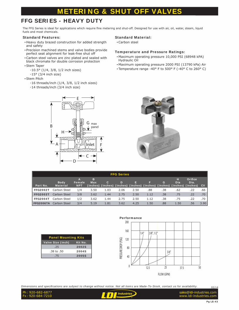
METERING & SHUT OFF VALVESFFG SERIES - HEAVY DUTYThe FFG Series is ideal for applications which require fi ne metering and shut-off. Designed for use with air, oil, water, steam, liquid fuels and most chemicals.
Standard Features: ▪Heavy duty brazed construction for added strength and safety ▪ Precision machined stems and valve bodies provide perfect seat alignment for leak-free shut off ▪Carbon steel valves are zinc plated and sealed with black chromate for double corrosion protection ▪Stem Taper
▫10.5° (1/4, 3/8, 1/2 inch sizes) ▫15° (3/4 inch size)
▪Stem Pitch ▫16 threads/inch (1/4, 3/8, 1/2 inch sizes) ▫14 threads/inch (3/4 inch size)
Standard Material: ▪Carbon steel
Temperature and Pressure Ratings: ▪Maximum operating pressure 10,000 PSI (68948 kPA) Hydraulic Oil ▪Maximum operating pressure 2000 PSI (13790 kPa) Air ▪ Temperature range -40° F to 500° F (-40° C to 260° C)
Panel Mounting KitsValve Size (inch) Kit No.
.25 2002S.38 to .50 2004S
.75 2005S
Performance
FFG Series
Part No.Body
Material
AFemale
NPT
BMax
(inches)C
(inches)D
(inches)E
(inches)F
(inches)G
(inches)
HDia
(inches)
Orifi ceDia.
(inches) CVFFG2002T Carbon Steel 1/4 3.50 1.03 2.06 2.50 .88 .38 .62 .22 .66FFG2003T Carbon Steel 3/8 3.62 1.44 2.75 2.50 1.12 .38 .75 .22 .70FFG2004T Carbon Steel 1/2 3.62 1.44 2.75 2.50 1.12 .38 .75 .22 .70FFG2006TA Carbon Steel 3/4 5.19 1.81 3.62 4.25 1.50 .88 1.50 .56 3.90
Ph : 920-682-6877Fx : 920-684-7210
Pg LE-43
Dimensions and specifi cations are subject to change without notice. Not all items are Made-To-Stock, contact us for availability. 02/14
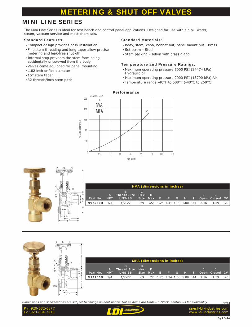
METERING & SHUT OFF VALVESMINI LINE SERIESThe Mini Line Series is ideal for test bench and control panel applications. Designed for use with air, oil, water, steam, vaccum service and most chemicals.
Standard Features: ▪Compact design provides easy installation ▪ Fine stem threading and long taper allow precise metering and leak-free shut off ▪ Internal stop prevents the stem from being accidentally unscrewed from the body ▪Valves come equipped for panel mounting ▪ .182 inch orifice diameter ▪15° stem taper ▪32 threads/inch stem pitch
Standard Materials: ▪Body, stem, knob, bonnet nut, panel mount nut - Brass ▪Set screw - Steel ▪Stem packing - Teflon with brass gland
Temperature and Pressure Ratings: ▪Maximum operating pressure 5000 PSI (34474 kPa) Hydraulic oil ▪Maximum operating pressure 2000 PSI (13790 kPa) Air ▪ Temperature range -40°F to 500°F (-40°C to 260°C)
NVA (dimensions in inches)
Part No.A
NPT
BThread Size
UNS-2B
CHexSize
DMax E F G H I
JOpen
JClosed CV
NVA250B 1/4 1/2-27 .69 .22 1.25 1.41 1.00 1.00 .44 2.16 1.59 .70
MFA (dimensions in inches)
Part No.A
NPT
BThread Size
UNS-2B
CHexSize
DMax E F G H I
JOpen
JClosed CV
MFA250B 1/4 1/2-27 .69 .22 1.25 1.34 1.00 1.00 .44 2.16 1.59 .70
Performance
Ph : 920-682-6877Fx : 920-684-7210
Pg LE-44
Dimensions and specifi cations are subject to change without notice. Not all items are Made-To-Stock, contact us for availability. 02/14

METERING & SHUT OFF VALVESMINI LINE SERIES (CONT’D)
MFG (dimensions in inches)
Part No.A
NPT
BThread Size
UNS-2B
CHexSize
DMax E F G H I
JOpen
JClosed CV
MFG250BF 1/4 1/2-27 .69 .22 1.25 2.00 1.00 .41 .44 2.16 1.78 .50
NVG (dimensions in inches)
Part No.A
NPT
BThread Size
UNS-2B
CHexSize
DMax E F G H I
JOpen
JClosed CV
NVG250B 1/4 1/2-27 .69 .22 1.25 1.34 1.00 1.00 .44 2.16 1.59 .70
Performance
Ph : 920-682-6877Fx : 920-684-7210
Pg LE-45
Dimensions and specifi cations are subject to change without notice. Not all items are Made-To-Stock, contact us for availability. 02/14
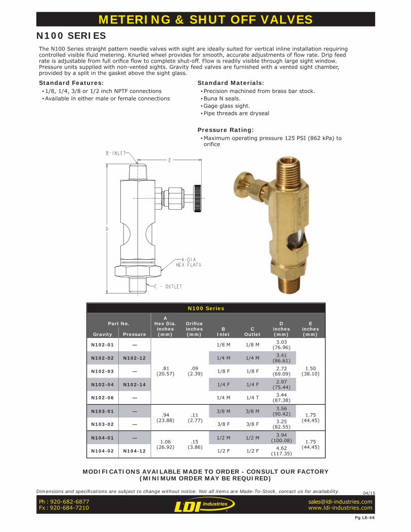
N100 Series
Part No.A
Hex Dia.inches(mm)
Orifi ceinches(mm)
BInlet
COutlet
Dinches(mm)
Einches(mm)Gravity Pressure
N102-01 —
.81(20.57)
.09 (2.39)
1/8 M 1/8 M 3.03(76.96)
1.50(38.10)
N102-02 N102-12 1/4 M 1/4 M 3.41(86.61)
N102-03 — 1/8 F 1/8 F 2.72(69.09)
N102-04 N102-14 1/4 F 1/4 F 2.97(75.44)
N102-06 — 1/4 M 1/4 T 3.44(87.38)
N103-01 —.94
(23.88) .11
(2.77)
3/8 M 3/8 M 3.56(90.42) 1.75
(44.45)N103-02 — 3/8 F 3/8 F 3.25
(82.55)
N104-01 —1.06
(26.92) .15
(3.86)
1/2 M 1/2 M 3.94(100.08) 1.75
(44.45)N104-02 N104-12 1/2 F 1/2 F 4.62
(117.35)
METERING & SHUT OFF VALVESN100 SERIESThe N100 Series straight pattern needle valves with sight are ideally suited for vertical inline installation requiring controlled visible fl uid metering. Knurled wheel provides for smooth, accurate adjustments of fl ow rate. Drip feed rate is adjustable from full orifi ce fl ow to complete shut-off. Flow is readily visible through large sight window. Pressure units supplied with non-vented sights. Gravity feed valves are furnished with a vented sight chamber, provided by a split in the gasket above the sight glass.
Standard Features: ▪1/8, 1/4, 3/8 or 1/2 inch NPTF connections ▪Available in either male or female connections
Standard Materials: ▪ Precision machined from brass bar stock. ▪Buna N seals. ▪Gage glass sight. ▪ Pipe threads are dryseal
Pressure Rating: ▪Maximum operating pressure 125 PSI (862 kPa) to orifice
MODIFICATIONS AVAILABLE MADE TO ORDER - CONSULT OUR FACTORY(MINIMUM ORDER MAY BE REQUIRED)
Ph : 920-682-6877Fx : 920-684-7210
Pg LE-46
Dimensions and specifi cations are subject to change without notice. Not all items are Made-To-Stock, contact us for availability. 04/15
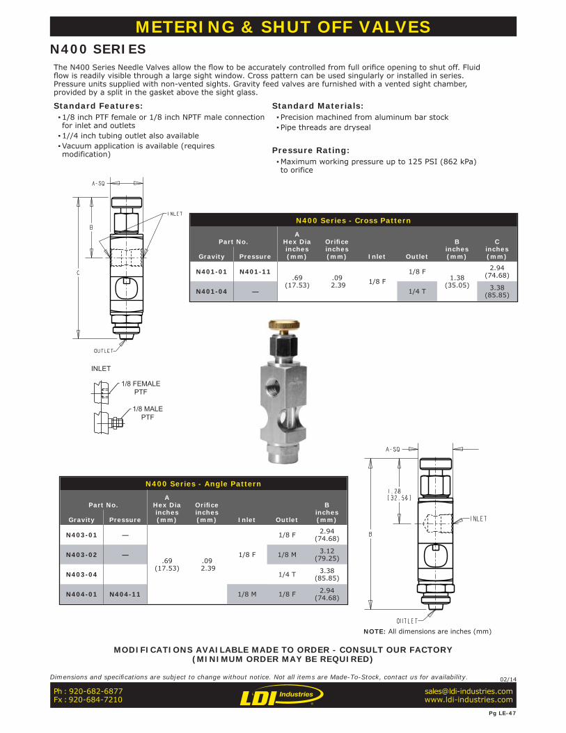
N400 Series - Cross Pattern
Part No.A
Hex Diainches(mm)
Orifi ceinches(mm) Inlet Outlet
Binches(mm)
Cinches(mm)Gravity Pressure
N401-01 N401-11.69
(17.53) .09
2.39 1/8 F1/8 F
1.38 (35.05)
2.94(74.68)
N401-04 — 1/4 T 3.38(85.85)
N400 Series - Angle Pattern
Part No.A
Hex Diainches(mm)
Orifi ceinches(mm) Inlet Outlet
Binches(mm)Gravity Pressure
N403-01 —
.69(17.53)
.09 2.39
1/8 F
1/8 F 2.94(74.68)
N403-02 — 1/8 M 3.12(79.25)
N403-04 1/4 T 3.38(85.85)
N404-01 N404-11 1/8 M 1/8 F 2.94(74.68)
METERING & SHUT OFF VALVESN400 SERIESThe N400 Series Needle Valves allow the fl ow to be accurately controlled from full orifi ce opening to shut off. Fluid fl ow is readily visible through a large sight window. Cross pattern can be used singularly or installed in series. Pressure units supplied with non-vented sights. Gravity feed valves are furnished with a vented sight chamber, provided by a split in the gasket above the sight glass.
Standard Features: ▪1/8 inch PTF female or 1/8 inch NPTF male connection for inlet and outlets ▪1//4 inch tubing outlet also available ▪Vacuum application is available (requires modification)
Standard Materials: ▪ Precision machined from aluminum bar stock ▪ Pipe threads are dryseal
Pressure Rating: ▪Maximum working pressure up to 125 PSI (862 kPa) to orifice
INLET
1/8 FEMALEPTF
1/8 MALEPTF
MODIFICATIONS AVAILABLE MADE TO ORDER - CONSULT OUR FACTORY(MINIMUM ORDER MAY BE REQUIRED)
Ph : 920-682-6877Fx : 920-684-7210
Pg LE-47
Dimensions and specifi cations are subject to change without notice. Not all items are Made-To-Stock, contact us for availability. 02/14
NOTE: All dimensions are inches (mm)

N470 Series - Angle Pattern
Part No.Outlet
Ainches(mm)Gravity Pressure
1/8 PTF Female Inlet
N471-02 — 1/8 Male 3.81(96.77)
N471-03 — 1/4 Tube 4.00(101.60)
1/8 NPTF Male Inlet
N472-03 N472-13 1/4 Tube 4.00(101.60)
1/4 NPTF Male Inlet
N473-03 — 1/4 Tube 4.00(101.60)
METERING & SHUT OFF VALVESN470 SERIESThe N470 Series toggle type valves are designed for controlled fl ow applications that require shutting off at times. This style of valve can be shut off and turned on again without affecting the previous preset drip rate. Fine adjustments can be made and easily locked by the knurled friction lock-ring. The drip rate is clearly visible through the large sight. Gravity feed valves are furnished with a vented sight chamber, provided by a split in the gasket above the sight glass. Valves for pressure applications have a solid gasket in both ends of the sight glass. (Non-vented)
Standard Materials: ▪Brass Construction ▪Buna N Seals ▪ Pipe threads are dryseal
Pressure Ratings: ▪ Pressure version is rated for maximum working pressure applications up to 125 PSI (862 kPa) ▪ .09 (2.39mm) minimum orifice
NOTE: ▪ Please refer to Appendix LE-3 on page LE-A3 for Toggle Valve Adjustment Instructions
NOTE: All dimensions are inches [mm]
Ph : 920-682-6877Fx : 920-684-7210
Pg LE-48
Dimensions and specifi cations are subject to change without notice. Not all items are Made-To-Stock, contact us for availability. 02/14
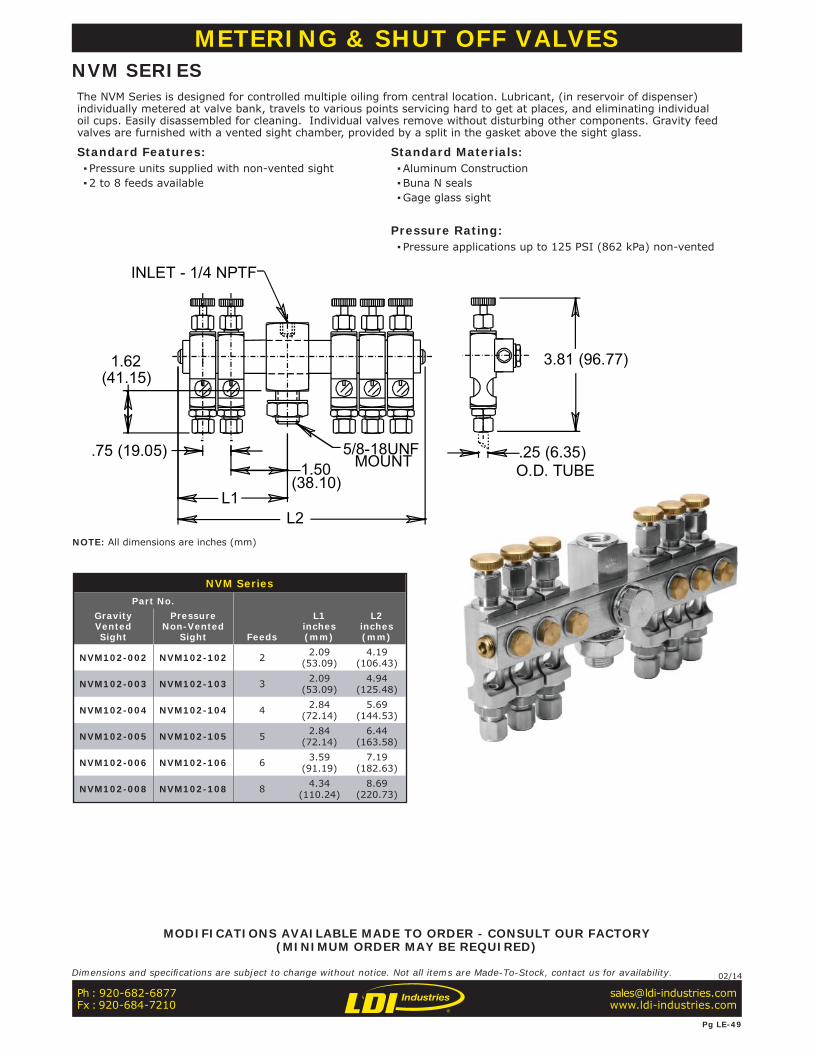
NVM SeriesPart No.
Feeds
L1inches(mm)
L2inches(mm)
GravityVentedSight
PressureNon-Vented
Sight
NVM102-002 NVM102-102 2 2.09(53.09)
4.19(106.43)
NVM102-003 NVM102-103 3 2.09(53.09)
4.94(125.48)
NVM102-004 NVM102-104 4 2.84(72.14)
5.69(144.53)
NVM102-005 NVM102-105 5 2.84(72.14)
6.44(163.58)
NVM102-006 NVM102-106 6 3.59(91.19)
7.19(182.63)
NVM102-008 NVM102-108 8 4.34(110.24)
8.69(220.73)
O.D. TUBE.25 (6.35)
3.81 (96.77)
INLET - 1/4 NPTF
5/8-18UNFMOUNT
(38.10)L1
.75 (19.05)
1.62
L2
1.50
(41.15)
METERING & SHUT OFF VALVESNVM SERIESThe NVM Series is designed for controlled multiple oiling from central location. Lubricant, (in reservoir of dispenser) individually metered at valve bank, travels to various points servicing hard to get at places, and eliminating individual oil cups. Easily disassembled for cleaning. Individual valves remove without disturbing other components. Gravity feed valves are furnished with a vented sight chamber, provided by a split in the gasket above the sight glass.
Standard Features: ▪ Pressure units supplied with non-vented sight ▪2 to 8 feeds available
Standard Materials: ▪Aluminum Construction ▪Buna N seals ▪Gage glass sight
Pressure Rating: ▪ Pressure applications up to 125 PSI (862 kPa) non-vented
MODIFICATIONS AVAILABLE MADE TO ORDER - CONSULT OUR FACTORY(MINIMUM ORDER MAY BE REQUIRED)
NOTE: All dimensions are inches (mm)
Ph : 920-682-6877Fx : 920-684-7210
Pg LE-49
Dimensions and specifi cations are subject to change without notice. Not all items are Made-To-Stock, contact us for availability. 02/14

METERING & SHUT OFF VALVESTMF SERIESThe TMF Series is designed for extremely precise control of hydraulic and pneumatic actuators. Provides metered fl ow in one direction and free fl ow in the reverse direction.
Standard Features: ▪Easy-to-read color bands and micrometer knobs for exact flow settings ▪Re-set repeatability within 1% ▪ Precision-machined Double-Step stem with fine threading provides accurate control, even at extremely low flows ▪Rugged, all metal construction-no plastic parts ▪Bleed holes in piston provide a cushion to soften closing impact and extend valve life ▪Brazed construction to withstand high pressure ▪Set screw provided to secure valve setting ▪Steel valves are zinc-plated AND sealed with black chromate for double corrosion protection ▪2° x 45° double-step stem taper ▪40 threads/inch stem pitch
Standard Materials: ▪Body - Steel ▪ Piston seal - Metal ▪ Piston, piston retainer, spring and stem, - Stainless Steel ▪Knob & color bands - Anodized Aluminum ▪Set screw - Steel ▪Stem packing - Viton O-Ring with Teflon backup
Temperature and Pressure Ratings: ▪Maximum operating pressure 5000 PSI (34474 kPa) ▪ Temperature range: -20°F to +400°F (-28°C to 204 °C) ▪Cracking Pressure (Check valve): 2 PSI (14 kPa)
TMF Series (dimensions in inches)
Part No.Body
MaterialPistonSeal
ANPT
Female
BSquare(inch) C
DMax
Orifi ceDiameter
CVFree-fl owDirection
CVControlled
Flow DirectionTMF375S Steel Metal 3/8 1.00 2.75 1.72 .22 2.95 .72TMF500S Steel Metal 1/2 1.12 3.44 2.25 .31 4.50 1.07TMF750S Steel Metal 3/4 1.50 3.88 2.47 .38 5.41 1.71
Performance
FLOW (GPM)
Ph : 920-682-6877Fx : 920-684-7210
Pg LE-50
Dimensions and specifi cations are subject to change without notice. Not all items are Made-To-Stock, contact us for availability. 02/14
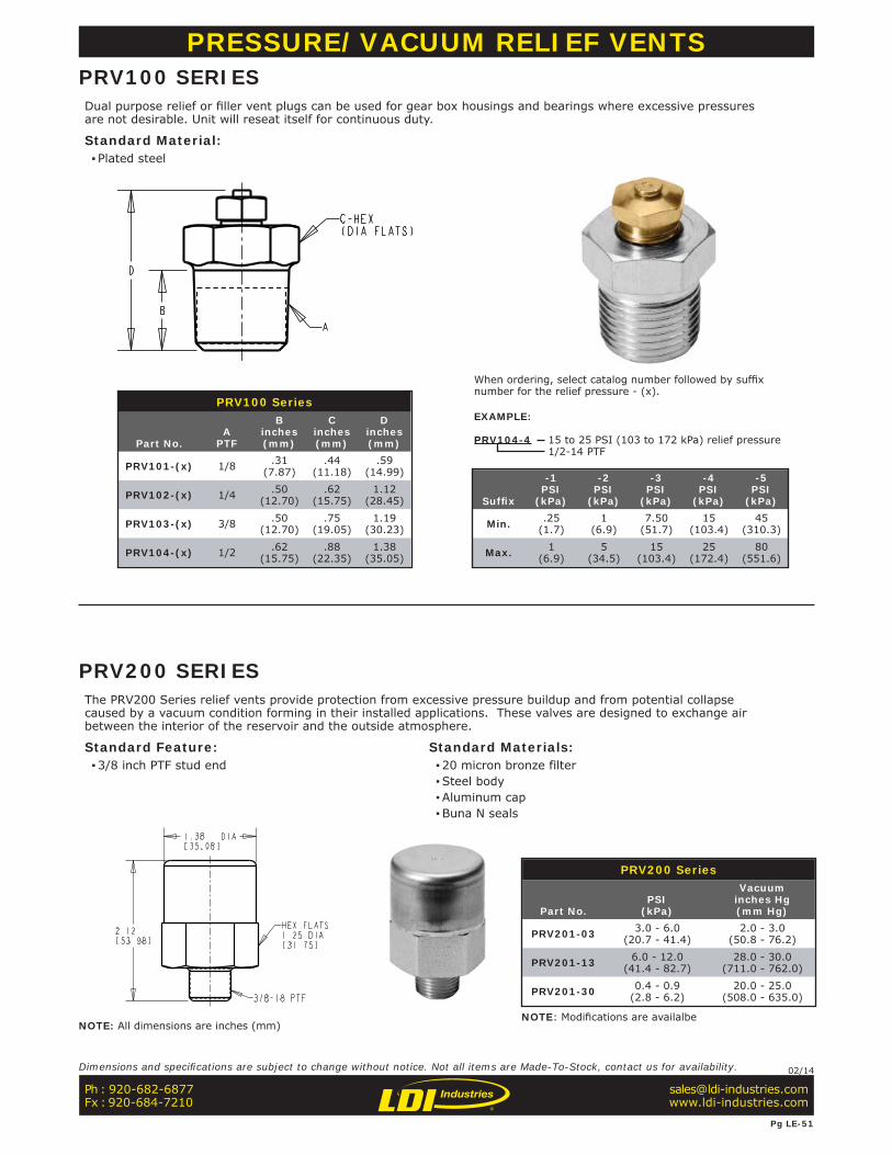
PRV100 Series
Part No.A
PTF
Binches(mm)
Cinches(mm)
Dinches(mm)
PRV101-(x) 1/8 .31(7.87)
.44(11.18)
.59(14.99)
PRV102-(x) 1/4 .50(12.70)
.62(15.75)
1.12(28.45)
PRV103-(x) 3/8 .50(12.70)
.75(19.05)
1.19(30.23)
PRV104-(x) 1/2 .62(15.75)
.88(22.35)
1.38(35.05)
Suffi x
-1PSI
(kPa)
-2PSI
(kPa)
-3PSI
(kPa)
-4PSI
(kPa)
-5PSI
(kPa)
Min. .25(1.7)
1(6.9)
7.50(51.7)
15(103.4)
45(310.3)
Max. 1(6.9)
5(34.5)
15(103.4)
25(172.4)
80(551.6)
When ordering, select catalog number followed by suffi x number for the relief pressure - (x).
EXAMPLE:
PRV104-4 15 to 25 PSI (103 to 172 kPa) relief pressure1/2-14 PTF
PRESSURE/VACUUM RELIEF VENTSPRV100 SERIESDual purpose relief or fi ller vent plugs can be used for gear box housings and bearings where excessive pressures are not desirable. Unit will reseat itself for continuous duty.
Standard Material: ▪ Plated steel
PRV200 Series
Part No.PSI
(kPa)
Vacuuminches Hg(mm Hg)
PRV201-03 3.0 - 6.0(20.7 - 41.4)
2.0 - 3.0(50.8 - 76.2)
PRV201-13 6.0 - 12.0(41.4 - 82.7)
28.0 - 30.0(711.0 - 762.0)
PRV201-30 0.4 - 0.9(2.8 - 6.2)
20.0 - 25.0(508.0 - 635.0)
PRV200 SERIESThe PRV200 Series relief vents provide protection from excessive pressure buildup and from potential collapse caused by a vacuum condition forming in their installed applications. These valves are designed to exchange air between the interior of the reservoir and the outside atmosphere.
Standard Feature: ▪3/8 inch PTF stud end
Standard Materials: ▪20 micron bronze filter ▪Steel body ▪Aluminum cap ▪Buna N seals
NOTE: Modifi cations are availalbe
Ph : 920-682-6877Fx : 920-684-7210
Pg LE-51
Dimensions and specifi cations are subject to change without notice. Not all items are Made-To-Stock, contact us for availability. 02/14
NOTE: All dimensions are inches (mm)
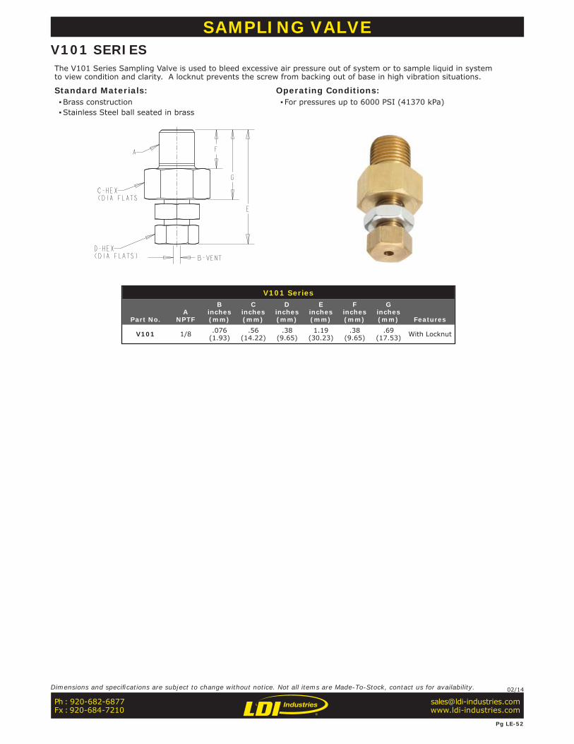
V101 Series
Part No.A
NPTF
Binches(mm)
Cinches(mm)
Dinches(mm)
Einches(mm)
Finches(mm)
Ginches(mm) Features
V101 1/8 .076(1.93)
.56(14.22)
.38(9.65)
1.19(30.23)
.38(9.65)
.69(17.53) With Locknut
SAMPLING VALVEV101 SERIESThe V101 Series Sampling Valve is used to bleed excessive air pressure out of system or to sample liquid in system to view condition and clarity. A locknut prevents the screw from backing out of base in high vibration situations.
Standard Materials: ▪Brass construction ▪Stainless Steel ball seated in brass
Operating Conditions: ▪ For pressures up to 6000 PSI (41370 kPa)
Ph : 920-682-6877Fx : 920-684-7210
Pg LE-52
Dimensions and specifi cations are subject to change without notice. Not all items are Made-To-Stock, contact us for availability. 02/14
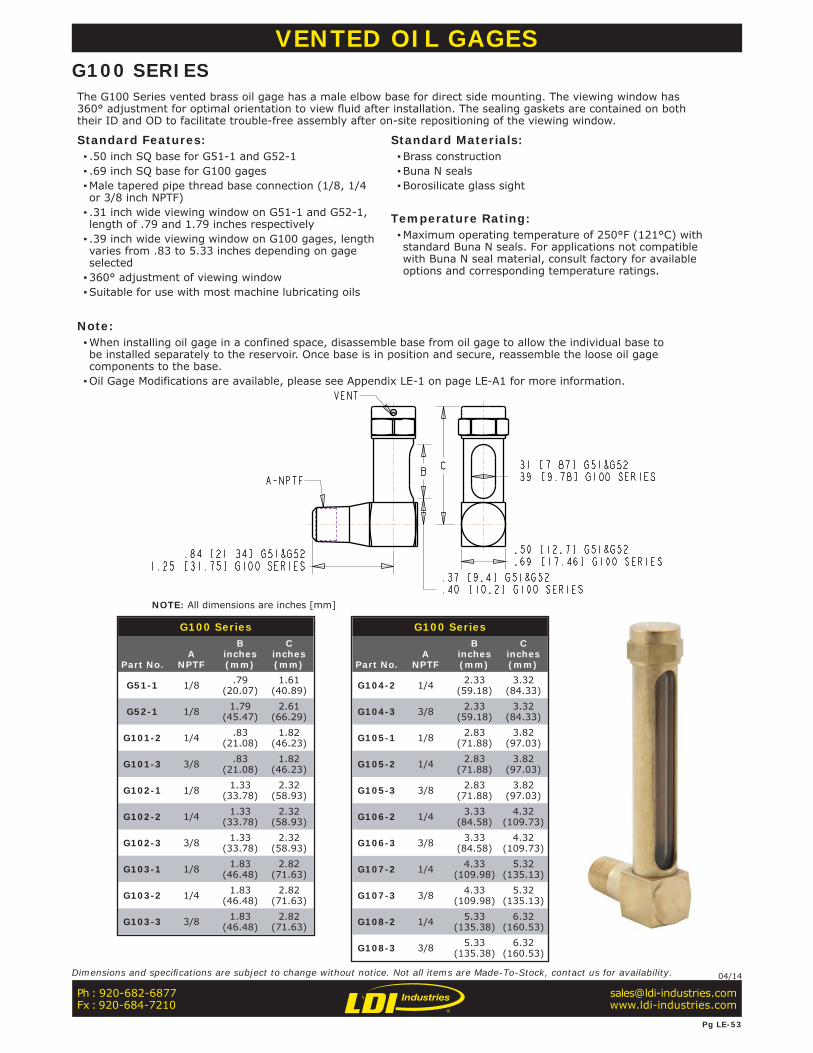
G100 Series
Part No.A
NPTF
Binches(mm)
Cinches(mm)
G51-1 1/8 .79(20.07)
1.61(40.89)
G52-1 1/8 1.79(45.47)
2.61(66.29)
G101-2 1/4 .83(21.08)
1.82(46.23)
G101-3 3/8 .83(21.08)
1.82(46.23)
G102-1 1/8 1.33(33.78)
2.32(58.93)
G102-2 1/4 1.33(33.78)
2.32(58.93)
G102-3 3/8 1.33(33.78)
2.32(58.93)
G103-1 1/8 1.83(46.48)
2.82(71.63)
G103-2 1/4 1.83(46.48)
2.82(71.63)
G103-3 3/8 1.83(46.48)
2.82(71.63)
G100 Series
Part No.A
NPTF
Binches(mm)
Cinches(mm)
G104-2 1/4 2.33(59.18)
3.32(84.33)
G104-3 3/8 2.33(59.18)
3.32(84.33)
G105-1 1/8 2.83(71.88)
3.82(97.03)
G105-2 1/4 2.83(71.88)
3.82(97.03)
G105-3 3/8 2.83(71.88)
3.82(97.03)
G106-2 1/4 3.33(84.58)
4.32(109.73)
G106-3 3/8 3.33(84.58)
4.32(109.73)
G107-2 1/4 4.33(109.98)
5.32(135.13)
G107-3 3/8 4.33(109.98)
5.32(135.13)
G108-2 1/4 5.33(135.38)
6.32(160.53)
G108-3 3/8 5.33(135.38)
6.32(160.53)
VENTED OIL GAGESG100 SERIESThe G100 Series vented brass oil gage has a male elbow base for direct side mounting. The viewing window has 360° adjustment for optimal orientation to view fl uid after installation. The sealing gaskets are contained on both their ID and OD to facilitate trouble-free assembly after on-site repositioning of the viewing window.
Standard Features: ▪ .50 inch SQ base for G51-1 and G52-1 ▪ .69 inch SQ base for G100 gages ▪Male tapered pipe thread base connection (1/8, 1/4 or 3/8 inch NPTF) ▪ .31 inch wide viewing window on G51-1 and G52-1, length of .79 and 1.79 inches respectively ▪ .39 inch wide viewing window on G100 gages, length varies from .83 to 5.33 inches depending on gage selected ▪360° adjustment of viewing window ▪Suitable for use with most machine lubricating oils
Standard Materials: ▪Brass construction ▪Buna N seals ▪Borosilicate glass sight
Temperature Rating: ▪Maximum operating temperature of 250°F (121°C) with standard Buna N seals. For applications not compatible with Buna N seal material, consult factory for available options and corresponding temperature ratings.
Note: ▪When installing oil gage in a confined space, disassemble base from oil gage to allow the individual base to be installed separately to the reservoir. Once base is in position and secure, reassemble the loose oil gage components to the base. ▪Oil Gage Modifications are available, please see Appendix LE-1 on page LE-A1 for more information.
NOTE: All dimensions are inches [mm]
Ph : 920-682-6877Fx : 920-684-7210
Dimensions and specifi cations are subject to change without notice. Not all items are Made-To-Stock, contact us for availability. 04/14
Pg LE-53
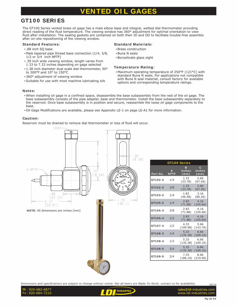
GT100 Series
Part No.A
NPTF
Binches(mm)
Cinches(mm)
GT102-2 1/4 1.33(33.78)
2.66(67.56)
GT102-3 3/8 1.33(33.78)
2.66(67.56)
GT103-2 1/4 1.83(46.48)
3.16(80.26)
GT105-2 1/4 2.83(71.88)
4.16(105.66)
GT105-3 3/8 2.83(71.88)
4.16(105.66)
GT105-4 1/2 2.83(71.88)
4.16(105.66)
GT107-4 1/2 4.33(109.98)
5.66(143.76)
GT108-2 1/4 5.33(135.38)
6.66(169.16)
GT108-4 1/2 5.33(135.38)
6.66(169.16)
GT108-5 3/4 5.33(135.38)
6.66(169.16)
GT109-5 3/4 7.33(186.18)
8.66(219.96)
VENTED OIL GAGESGT100 SERIESThe GT100 Series vented brass oil gage has a male elbow base and integral, wetted dial thermometer providing direct reading of the fl uid temperature. The viewing window has 360° adjustment for optimal orientation to view fl uid after installation. The sealing gaskets are contained on both their ID and OD to facilitate trouble-free assembly after on-site repositioning of the viewing window.
Standard Features: ▪ .88 inch SQ base ▪Male tapered pipe thread base connection (1/4, 3/8, 1/2 or 3/4 inch NPTF) ▪ .39 inch wide viewing window, length varies from 1.33 to 7.33 inches depending on gage selected ▪1.38 inch diameter dual scale dial thermometer, 50° to 300°F and 10° to 150°C ▪360° adjustment of viewing window ▪Suitable for use with most machine lubricating oils
Standard Materials: ▪Brass construction ▪Buna N seals ▪Borosilicate glass sight
Temperature Rating: ▪Maximum operating temperature of 250°F (121°C) with standard Buna N seals. For applications not compatible with Buna N seal material, consult factory for available options and corresponding temperature ratings.
Notes: ▪When installing oil gage in a confined space, disassemble the base subassembly from the rest of the oil gage. The base subassembly consists of the pipe adapter, base and thermometer. Install the base subassembly separately to the reservoir. Once base subassembly is in position and secure, reassemble the loose oil gage components to the base. ▪Oil Gage Modifications are available, please see Appendix LE-1 on page LE-A1 for more information.
Caution:Reservoir must be drained to remove dial thermometer or loss of fl uid will occur.
NOTE: All dimensions are inches [mm]
Ph : 920-682-6877Fx : 920-684-7210
Pg LE-54
Dimensions and specifi cations are subject to change without notice. Not all items are Made-To-Stock, contact us for availability. 02/14
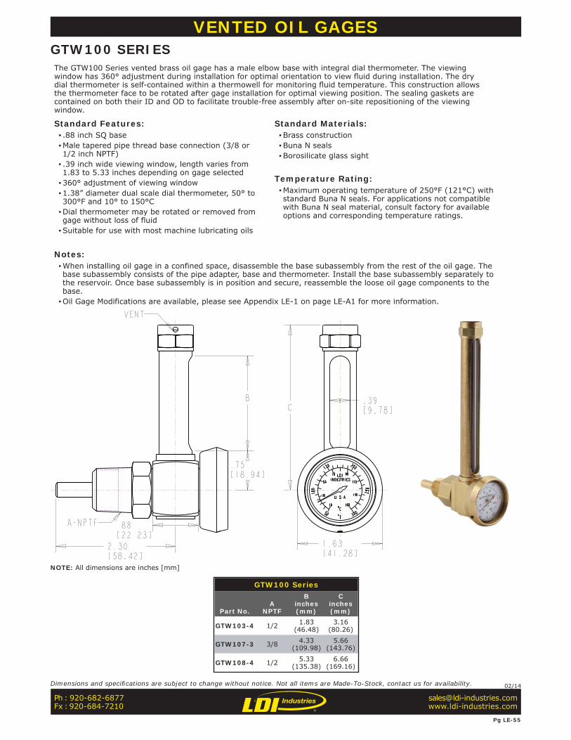
GTW100 Series
Part No.A
NPTF
Binches(mm)
Cinches(mm)
GTW103-4 1/2 1.83(46.48)
3.16(80.26)
GTW107-3 3/8 4.33(109.98)
5.66(143.76)
GTW108-4 1/2 5.33(135.38)
6.66(169.16)
VENTED OIL GAGESGTW100 SERIESThe GTW100 Series vented brass oil gage has a male elbow base with integral dial thermometer. The viewing window has 360° adjustment during installation for optimal orientation to view fl uid during installation. The dry dial thermometer is self-contained within a thermowell for monitoring fl uid temperature. This construction allows the thermometer face to be rotated after gage installation for optimal viewing position. The sealing gaskets are contained on both their ID and OD to facilitate trouble-free assembly after on-site repositioning of the viewing window.
Standard Features: ▪ .88 inch SQ base ▪Male tapered pipe thread base connection (3/8 or 1/2 inch NPTF) ▪ .39 inch wide viewing window, length varies from 1.83 to 5.33 inches depending on gage selected ▪360° adjustment of viewing window ▪1.38” diameter dual scale dial thermometer, 50° to 300°F and 10° to 150°C ▪Dial thermometer may be rotated or removed from gage without loss of fluid ▪Suitable for use with most machine lubricating oils
Standard Materials: ▪Brass construction ▪Buna N seals ▪Borosilicate glass sight
Temperature Rating: ▪Maximum operating temperature of 250°F (121°C) with standard Buna N seals. For applications not compatible with Buna N seal material, consult factory for available options and corresponding temperature ratings.
Notes: ▪When installing oil gage in a confined space, disassemble the base subassembly from the rest of the oil gage. The base subassembly consists of the pipe adapter, base and thermometer. Install the base subassembly separately to the reservoir. Once base subassembly is in position and secure, reassemble the loose oil gage components to the base. ▪Oil Gage Modifications are available, please see Appendix LE-1 on page LE-A1 for more information.
NOTE: All dimensions are inches [mm]
Ph : 920-682-6877Fx : 920-684-7210
Pg LE-55
Dimensions and specifi cations are subject to change without notice. Not all items are Made-To-Stock, contact us for availability. 02/14
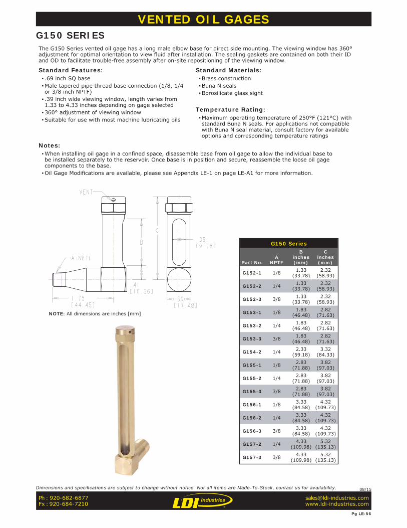
G150 Series
Part No.A
NPTF
Binches(mm)
Cinches(mm)
G152-1 1/8 1.33(33.78)
2.32(58.93)
G152-2 1/4 1.33(33.78)
2.32(58.93)
G152-3 3/8 1.33(33.78)
2.32(58.93)
G153-1 1/8 1.83(46.48)
2.82(71.63)
G153-2 1/4 1.83(46.48)
2.82(71.63)
G153-3 3/8 1.83(46.48)
2.82(71.63)
G154-2 1/4 2.33(59.18)
3.32(84.33)
G155-1 1/8 2.83(71.88)
3.82(97.03)
G155-2 1/4 2.83(71.88)
3.82(97.03)
G155-3 3/8 2.83(71.88)
3.82(97.03)
G156-1 1/8 3.33(84.58)
4.32(109.73)
G156-2 1/4 3.33(84.58)
4.32(109.73)
G156-3 3/8 3.33(84.58)
4.32(109.73)
G157-2 1/4 4.33(109.98)
5.32(135.13)
G157-3 3/8 4.33(109.98)
5.32(135.13)
VENTED OIL GAGESG150 SERIESThe G150 Series vented oil gage has a long male elbow base for direct side mounting. The viewing window has 360° adjustment for optimal orientation to view fl uid after installation. The sealing gaskets are contained on both their ID and OD to facilitate trouble-free assembly after on-site repositioning of the viewing window.
Standard Features: ▪ .69 inch SQ base ▪Male tapered pipe thread base connection (1/8, 1/4 or 3/8 inch NPTF) ▪ .39 inch wide viewing window, length varies from 1.33 to 4.33 inches depending on gage selected ▪360° adjustment of viewing window ▪Suitable for use with most machine lubricating oils
Standard Materials: ▪Brass construction ▪Buna N seals ▪Borosilicate glass sight
Temperature Rating: ▪Maximum operating temperature of 250°F (121°C) with standard Buna N seals. For applications not compatible with Buna N seal material, consult factory for available options and corresponding temperature ratings
Notes: ▪When installing oil gage in a confined space, disassemble base from oil gage to allow the individual base to be installed separately to the reservoir. Once base is in position and secure, reassemble the loose oil gage components to the base. ▪Oil Gage Modifications are available, please see Appendix LE-1 on page LE-A1 for more information.
NOTE: All dimensions are inches [mm]
Ph : 920-682-6877Fx : 920-684-7210
Pg LE-56
Dimensions and specifi cations are subject to change without notice. Not all items are Made-To-Stock, contact us for availability. 08/15
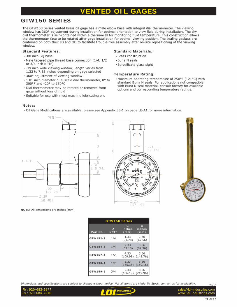
GTW150 Series
Part No.A
NPTF
Binches(mm)
Cinches(mm)
GTW152-2 1/4 1.33(33.78)
2.66(67.56)
GTW154-2 1/4 2.33(59.18)
3.66(92.96)
GTW157-4 1/2 4.33(109.98)
5.66(143.76)
GTW158-4 1/2 5.33(135.38)
6.66(169.16)
GTW159-5 3/4 7.33(186.19)
8.66(219.96)
VENTED OIL GAGESGTW150 SERIESThe GTW150 Series vented brass oil gage has a male elbow base with integral dial thermometer. The viewing window has 360° adjustment during installation for optimal orientation to view fl uid during installation. The dry dial thermometer is self-contained within a thermowell for monitoring fl uid temperature. This construction allows the thermometer face to be rotated after gage installation for optimal viewing position. The sealing gaskets are contained on both their ID and OD to facilitate trouble-free assembly after on-site repositioning of the viewing window.
Standard Features: ▪ .88 inch SQ base ▪Male tapered pipe thread base connection (1/4, 1/2 or 3/4 inch NPTF) ▪ .39 inch wide viewing window, length varies from 1.33 to 7.33 inches depending on gage selected ▪360° adjustment of viewing window ▪1.81 inch diameter dual scale dial thermometer, 0° to 300°F and -20° to 150°C ▪Dial thermometer may be rotated or removed from gage without loss of fluid ▪Suitable for use with most machine lubricating oils
Standard Materials: ▪Brass construction ▪Buna N seals ▪Borosilicate glass sight
Temperature Rating: ▪Maximum operating temperature of 250°F (121°C) with standard Buna N seals. For applications not compatible with Buna N seal material, consult factory for available options and corresponding temperature ratings.
Notes: ▪Oil Gage Modifications are available, please see Appendix LE-1 on page LE-A1 for more information.
NOTE: All dimensions are inches [mm]
Ph : 920-682-6877Fx : 920-684-7210
Pg LE-57
Dimensions and specifi cations are subject to change without notice. Not all items are Made-To-Stock, contact us for availability. 02/14
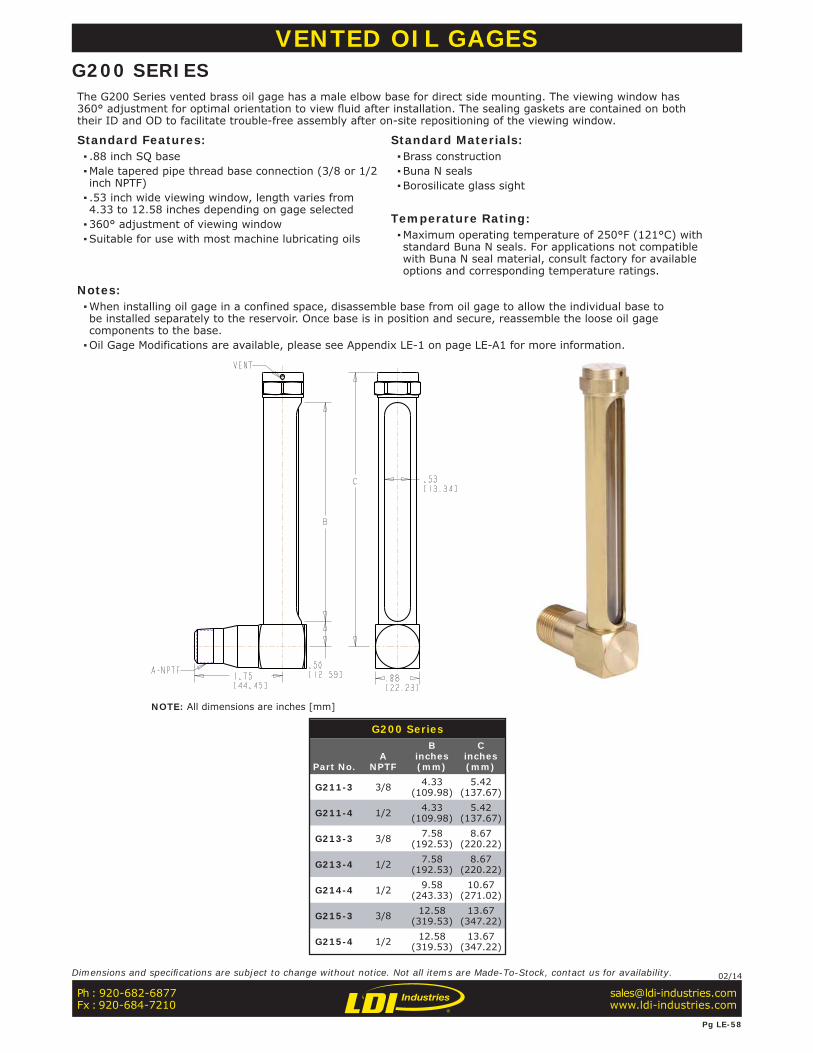
G200 Series
Part No.A
NPTF
Binches(mm)
Cinches(mm)
G211-3 3/8 4.33(109.98)
5.42(137.67)
G211-4 1/2 4.33(109.98)
5.42(137.67)
G213-3 3/8 7.58(192.53)
8.67(220.22)
G213-4 1/2 7.58(192.53)
8.67(220.22)
G214-4 1/2 9.58(243.33)
10.67(271.02)
G215-3 3/8 12.58(319.53)
13.67(347.22)
G215-4 1/2 12.58(319.53)
13.67(347.22)
VENTED OIL GAGESG200 SERIESThe G200 Series vented brass oil gage has a male elbow base for direct side mounting. The viewing window has 360° adjustment for optimal orientation to view fl uid after installation. The sealing gaskets are contained on both their ID and OD to facilitate trouble-free assembly after on-site repositioning of the viewing window.
Standard Features: ▪ .88 inch SQ base ▪Male tapered pipe thread base connection (3/8 or 1/2 inch NPTF) ▪ .53 inch wide viewing window, length varies from 4.33 to 12.58 inches depending on gage selected ▪360° adjustment of viewing window ▪Suitable for use with most machine lubricating oils
Standard Materials: ▪Brass construction ▪Buna N seals ▪Borosilicate glass sight
Temperature Rating: ▪Maximum operating temperature of 250°F (121°C) with standard Buna N seals. For applications not compatible with Buna N seal material, consult factory for available options and corresponding temperature ratings.
Notes: ▪When installing oil gage in a confined space, disassemble base from oil gage to allow the individual base to be installed separately to the reservoir. Once base is in position and secure, reassemble the loose oil gage components to the base. ▪Oil Gage Modifications are available, please see Appendix LE-1 on page LE-A1 for more information.
NOTE: All dimensions are inches [mm]
Ph : 920-682-6877Fx : 920-684-7210
Pg LE-58
Dimensions and specifi cations are subject to change without notice. Not all items are Made-To-Stock, contact us for availability. 02/14
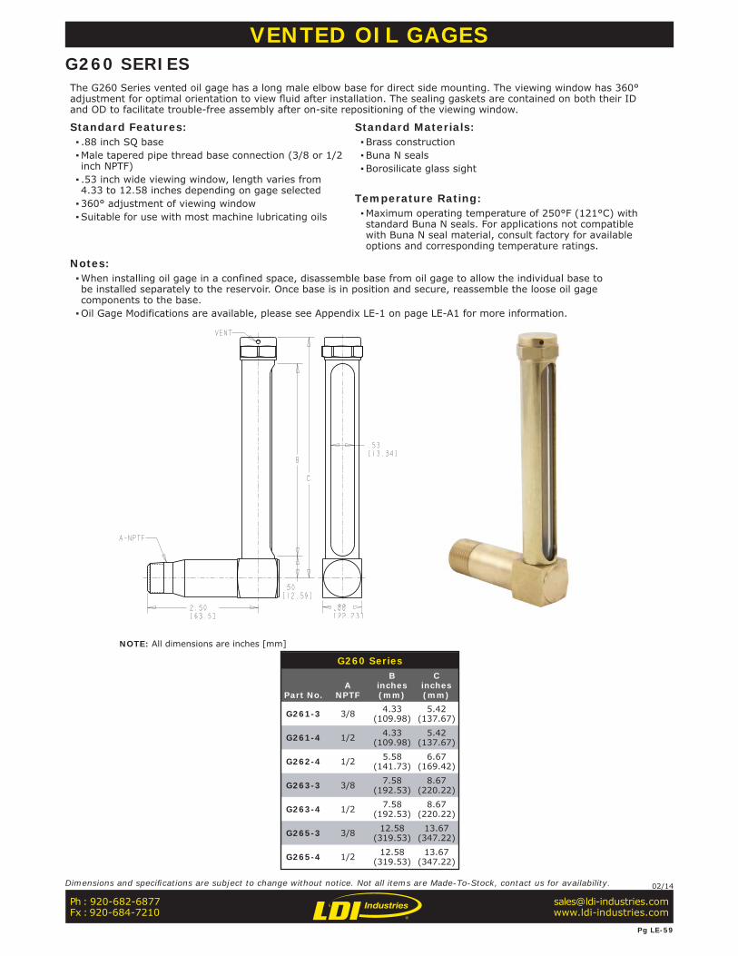
G260 Series
Part No.A
NPTF
Binches(mm)
Cinches(mm)
G261-3 3/8 4.33(109.98)
5.42(137.67)
G261-4 1/2 4.33(109.98)
5.42(137.67)
G262-4 1/2 5.58(141.73)
6.67(169.42)
G263-3 3/8 7.58(192.53)
8.67(220.22)
G263-4 1/2 7.58(192.53)
8.67(220.22)
G265-3 3/8 12.58(319.53)
13.67(347.22)
G265-4 1/2 12.58(319.53)
13.67(347.22)
VENTED OIL GAGESG260 SERIESThe G260 Series vented oil gage has a long male elbow base for direct side mounting. The viewing window has 360° adjustment for optimal orientation to view fl uid after installation. The sealing gaskets are contained on both their ID and OD to facilitate trouble-free assembly after on-site repositioning of the viewing window.
Standard Features: ▪ .88 inch SQ base ▪Male tapered pipe thread base connection (3/8 or 1/2 inch NPTF) ▪ .53 inch wide viewing window, length varies from 4.33 to 12.58 inches depending on gage selected ▪360° adjustment of viewing window ▪Suitable for use with most machine lubricating oils
Standard Materials: ▪Brass construction ▪Buna N seals ▪Borosilicate glass sight
Temperature Rating: ▪Maximum operating temperature of 250°F (121°C) with standard Buna N seals. For applications not compatible with Buna N seal material, consult factory for available options and corresponding temperature ratings.
Notes: ▪When installing oil gage in a confined space, disassemble base from oil gage to allow the individual base to be installed separately to the reservoir. Once base is in position and secure, reassemble the loose oil gage components to the base. ▪Oil Gage Modifications are available, please see Appendix LE-1 on page LE-A1 for more information.
NOTE: All dimensions are inches [mm]
Ph : 920-682-6877Fx : 920-684-7210
Pg LE-59
Dimensions and specifi cations are subject to change without notice. Not all items are Made-To-Stock, contact us for availability. 02/14

G300 Series (cont’d)
Part No.A
NPTF
Binches(mm)
Cinches(mm)
Dinches(mm)
HEXFLATS
G305-2 1/4 1.06(26.87)
2.83(71.88)
4.48(113.79)
.69(17.53)
G305-3 3/8 1.06(26.87)
2.83(71.88)
4.48(113.79)
.69(17.53)
G306-2 1/4 1.06(26.87)
3.33(84.58)
4.98(126.49)
.69(17.53)
G306-3 3/8 1.06(26.87)
3.33(84.58)
4.98(126.49)
.69(17.53)
G307-1 1/8 .87(22.10)
4.33(109.98)
5.79(147.07)
.69(17.53)
G307-2 1/4 1.06(26.87)
4.33(109.98)
5.98(151.89)
.69(17.53)
G307-3 3/8 1.06(26.87)
4.33(109.98)
5.98(151.89)
.69(17.53)
G308-2 1/4 1.06(26.87)
5.33(135.38)
6.98(177.29)
.69(17.53)
G308-3 3/8 1.06(26.87)
5.33(135.38)
6.98(177.29)
.69(17.53)
G309-2 1/4 1.06(26.87)
7.33(186.18)
8.98(228.09)
.69(17.53)
G309-3 3/8 1.06(26.87)
7.33(186.18)
8.98(228.09)
.69(17.53)
G300 Series
Part No.A
NPTF
Binches(mm)
Cinches(mm)
Dinches(mm)
HEXFLATS
G62-1 1/8 .79(20.07)
1.79(45.47)
3.06(77.72)
.50(12.70)
G301-2 1/4 1.06(26.87)
.83(21.08)
2.48(62.99)
.69(17.53)
G302-1 1/8 .87(22.10)
1.33(33.78)
2.29(58.17)
.69(17.53)
G302-2 1/4 1.06(26.87)
1.33(33.78)
2.98(75.69)
.69(17.53)
G302-3 3/8 1.06(26.87)
1.33(33.78)
2.98(75.69)
.69(17.53)
G303-1 1/8 .87(22.10)
1.83(46.48)
3.29 (83.57)
.69(17.53)
G303-2 1/4 1.06(26.87)
1.83(46.48)
3.48(88.39)
.69(17.53)
G303-3 3/8 1.06(26.87)
1.83(46.48)
3.48(88.39)
.69(17.53)
G304-2 1/4 1.06(26.87)
2.33(59.18)
3.98(101.09)
.69(17.53)
G304-3 3/8 1.06(26.87)
2.33(59.18)
3.98(101.09)
.69(17.53)
VENTED OIL GAGESG300 SERIESThe G300 Series vented brass oil gage has a straight hex base with male pipe thread. A shield with machined viewing window surrounds the tubular glass sight. The viewing window has 360° adjustment for optimal orientation to view fl uid after installation. The sealing gaskets are contained on both their ID and OD to facilitate trouble-free assembly after on-site repositioning of the viewing window.
Standard Features: ▪Gage base machined from brass hex bar stock ▪Male tapered pipe thread base connection (1/8, 1/4 or 3/8 inch NPTF) ▪ .39 inch wide viewing window, length varies from 1.79 to 7.33 inches depending on gage selected ▪360° adjustment of viewing window ▪Suitable for use with most machine lubricating oils
Standard Materials: ▪Brass construction ▪Buna N seals ▪Borosilicate glass sight
Temperature Rating: ▪Maximum operating temperature of 250°F (121°C) with standard Buna N seals. For applications not compatible with Buna N seal material, consult factory for available options and corresponding temperature ratings.
Note: ▪Oil Gage Modifications are available, please see Appendix LE-1 on page LE-A1 for more information.
NOTE: All dimensions are inches [mm]
Ph : 920-682-6877Fx : 920-684-7210
Pg LE-60
Dimensions and specifi cations are subject to change without notice. Not all items are Made-To-Stock, contact us for availability. 02/14
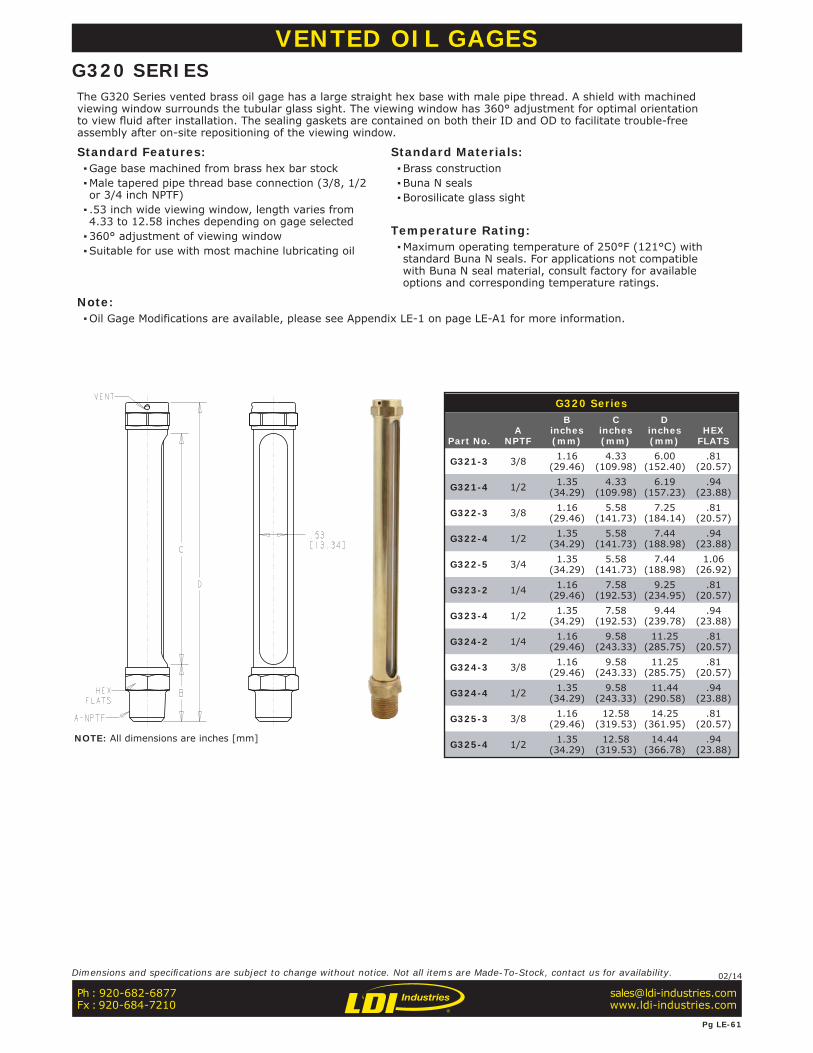
G320 Series
Part No.A
NPTF
Binches(mm)
Cinches(mm)
Dinches(mm)
HEXFLATS
G321-3 3/8 1.16(29.46)
4.33(109.98)
6.00(152.40)
.81(20.57)
G321-4 1/2 1.35(34.29)
4.33(109.98)
6.19(157.23)
.94(23.88)
G322-3 3/8 1.16(29.46)
5.58(141.73)
7.25(184.14)
.81(20.57)
G322-4 1/2 1.35(34.29)
5.58(141.73)
7.44(188.98)
.94(23.88)
G322-5 3/4 1.35(34.29)
5.58(141.73)
7.44(188.98)
1.06(26.92)
G323-2 1/4 1.16(29.46)
7.58(192.53)
9.25(234.95)
.81(20.57)
G323-4 1/2 1.35(34.29)
7.58(192.53)
9.44(239.78)
.94(23.88)
G324-2 1/4 1.16(29.46)
9.58(243.33)
11.25(285.75)
.81(20.57)
G324-3 3/8 1.16(29.46)
9.58(243.33)
11.25(285.75)
.81(20.57)
G324-4 1/2 1.35(34.29)
9.58(243.33)
11.44(290.58)
.94(23.88)
G325-3 3/8 1.16(29.46)
12.58(319.53)
14.25(361.95)
.81(20.57)
G325-4 1/2 1.35(34.29)
12.58(319.53)
14.44(366.78)
.94(23.88)
VENTED OIL GAGESG320 SERIESThe G320 Series vented brass oil gage has a large straight hex base with male pipe thread. A shield with machined viewing window surrounds the tubular glass sight. The viewing window has 360° adjustment for optimal orientation to view fl uid after installation. The sealing gaskets are contained on both their ID and OD to facilitate trouble-free assembly after on-site repositioning of the viewing window.
Standard Features: ▪Gage base machined from brass hex bar stock ▪Male tapered pipe thread base connection (3/8, 1/2 or 3/4 inch NPTF) ▪ .53 inch wide viewing window, length varies from 4.33 to 12.58 inches depending on gage selected ▪360° adjustment of viewing window ▪Suitable for use with most machine lubricating oil
Standard Materials: ▪Brass construction ▪Buna N seals ▪Borosilicate glass sight
Temperature Rating: ▪Maximum operating temperature of 250°F (121°C) with standard Buna N seals. For applications not compatible with Buna N seal material, consult factory for available options and corresponding temperature ratings.
Note: ▪Oil Gage Modifications are available, please see Appendix LE-1 on page LE-A1 for more information.
NOTE: All dimensions are inches [mm]
Ph : 920-682-6877Fx : 920-684-7210
Pg LE-61
Dimensions and specifi cations are subject to change without notice. Not all items are Made-To-Stock, contact us for availability. 02/14
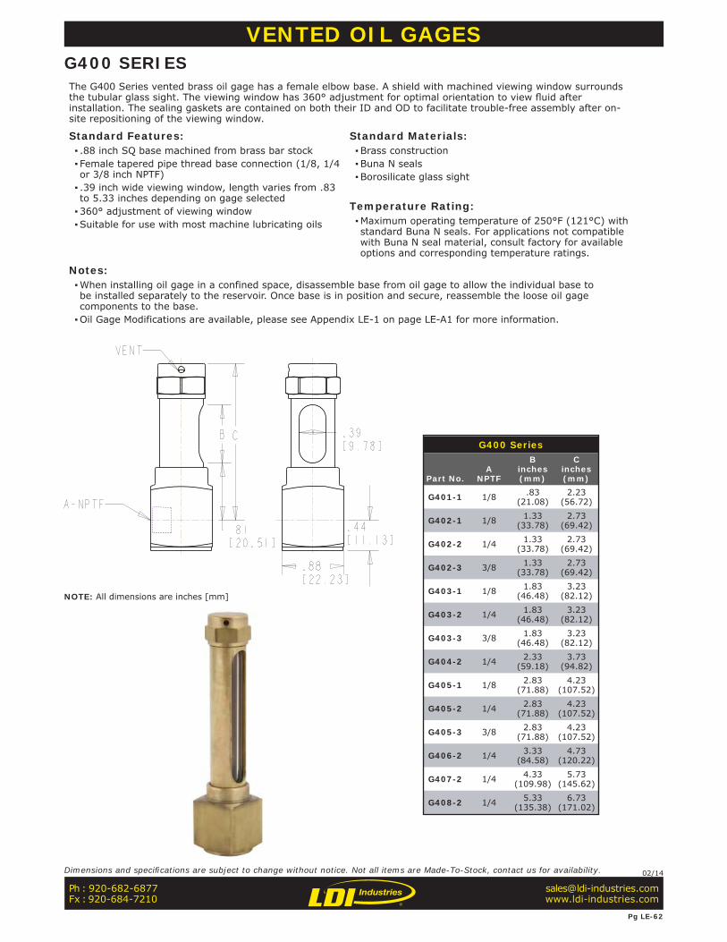
G400 Series
Part No.A
NPTF
Binches(mm)
Cinches(mm)
G401-1 1/8 .83(21.08)
2.23(56.72)
G402-1 1/8 1.33(33.78)
2.73(69.42)
G402-2 1/4 1.33(33.78)
2.73(69.42)
G402-3 3/8 1.33(33.78)
2.73(69.42)
G403-1 1/8 1.83(46.48)
3.23(82.12)
G403-2 1/4 1.83(46.48)
3.23(82.12)
G403-3 3/8 1.83(46.48)
3.23(82.12)
G404-2 1/4 2.33(59.18)
3.73(94.82)
G405-1 1/8 2.83(71.88)
4.23(107.52)
G405-2 1/4 2.83(71.88)
4.23(107.52)
G405-3 3/8 2.83(71.88)
4.23(107.52)
G406-2 1/4 3.33(84.58)
4.73(120.22)
G407-2 1/4 4.33(109.98)
5.73(145.62)
G408-2 1/4 5.33(135.38)
6.73(171.02)
VENTED OIL GAGESG400 SERIESThe G400 Series vented brass oil gage has a female elbow base. A shield with machined viewing window surrounds the tubular glass sight. The viewing window has 360° adjustment for optimal orientation to view fl uid after installation. The sealing gaskets are contained on both their ID and OD to facilitate trouble-free assembly after on-site repositioning of the viewing window.
Standard Features: ▪ .88 inch SQ base machined from brass bar stock ▪ Female tapered pipe thread base connection (1/8, 1/4 or 3/8 inch NPTF) ▪ .39 inch wide viewing window, length varies from .83 to 5.33 inches depending on gage selected ▪360° adjustment of viewing window ▪Suitable for use with most machine lubricating oils
Standard Materials: ▪Brass construction ▪Buna N seals ▪Borosilicate glass sight
Temperature Rating: ▪Maximum operating temperature of 250°F (121°C) with standard Buna N seals. For applications not compatible with Buna N seal material, consult factory for available options and corresponding temperature ratings.
Notes: ▪When installing oil gage in a confined space, disassemble base from oil gage to allow the individual base to be installed separately to the reservoir. Once base is in position and secure, reassemble the loose oil gage components to the base. ▪Oil Gage Modifications are available, please see Appendix LE-1 on page LE-A1 for more information.
NOTE: All dimensions are inches [mm]
Ph : 920-682-6877Fx : 920-684-7210
Pg LE-62
Dimensions and specifi cations are subject to change without notice. Not all items are Made-To-Stock, contact us for availability. 02/14
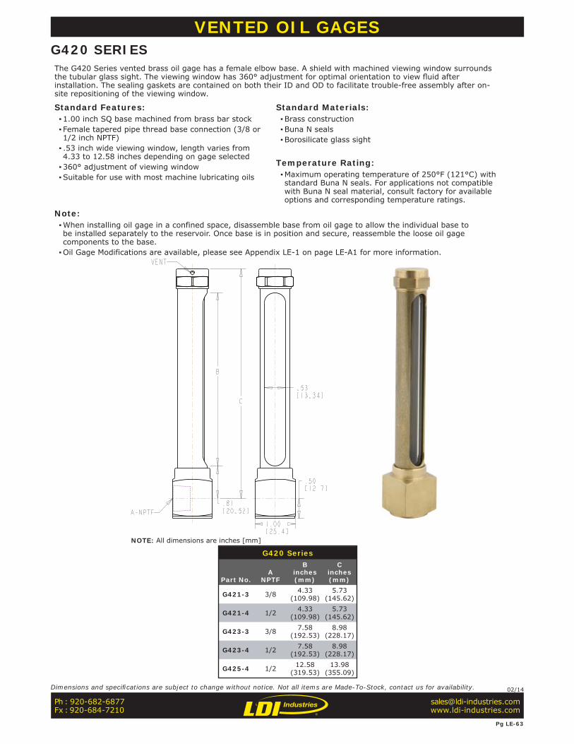
G420 Series
Part No.A
NPTF
Binches(mm)
Cinches(mm)
G421-3 3/8 4.33(109.98)
5.73(145.62)
G421-4 1/2 4.33(109.98)
5.73(145.62)
G423-3 3/8 7.58(192.53)
8.98(228.17)
G423-4 1/2 7.58(192.53)
8.98(228.17)
G425-4 1/2 12.58(319.53)
13.98(355.09)
VENTED OIL GAGESG420 SERIESThe G420 Series vented brass oil gage has a female elbow base. A shield with machined viewing window surrounds the tubular glass sight. The viewing window has 360° adjustment for optimal orientation to view fl uid after installation. The sealing gaskets are contained on both their ID and OD to facilitate trouble-free assembly after on-site repositioning of the viewing window.
Standard Features: ▪1.00 inch SQ base machined from brass bar stock ▪ Female tapered pipe thread base connection (3/8 or 1/2 inch NPTF) ▪ .53 inch wide viewing window, length varies from 4.33 to 12.58 inches depending on gage selected ▪360° adjustment of viewing window ▪Suitable for use with most machine lubricating oils
Standard Materials: ▪Brass construction ▪Buna N seals ▪Borosilicate glass sight
Temperature Rating: ▪Maximum operating temperature of 250°F (121°C) with standard Buna N seals. For applications not compatible with Buna N seal material, consult factory for available options and corresponding temperature ratings.
Note: ▪When installing oil gage in a confined space, disassemble base from oil gage to allow the individual base to be installed separately to the reservoir. Once base is in position and secure, reassemble the loose oil gage components to the base. ▪Oil Gage Modifications are available, please see Appendix LE-1 on page LE-A1 for more information.
NOTE: All dimensions are inches [mm]
Ph : 920-682-6877Fx : 920-684-7210
Pg LE-63
Dimensions and specifi cations are subject to change without notice. Not all items are Made-To-Stock, contact us for availability. 02/14
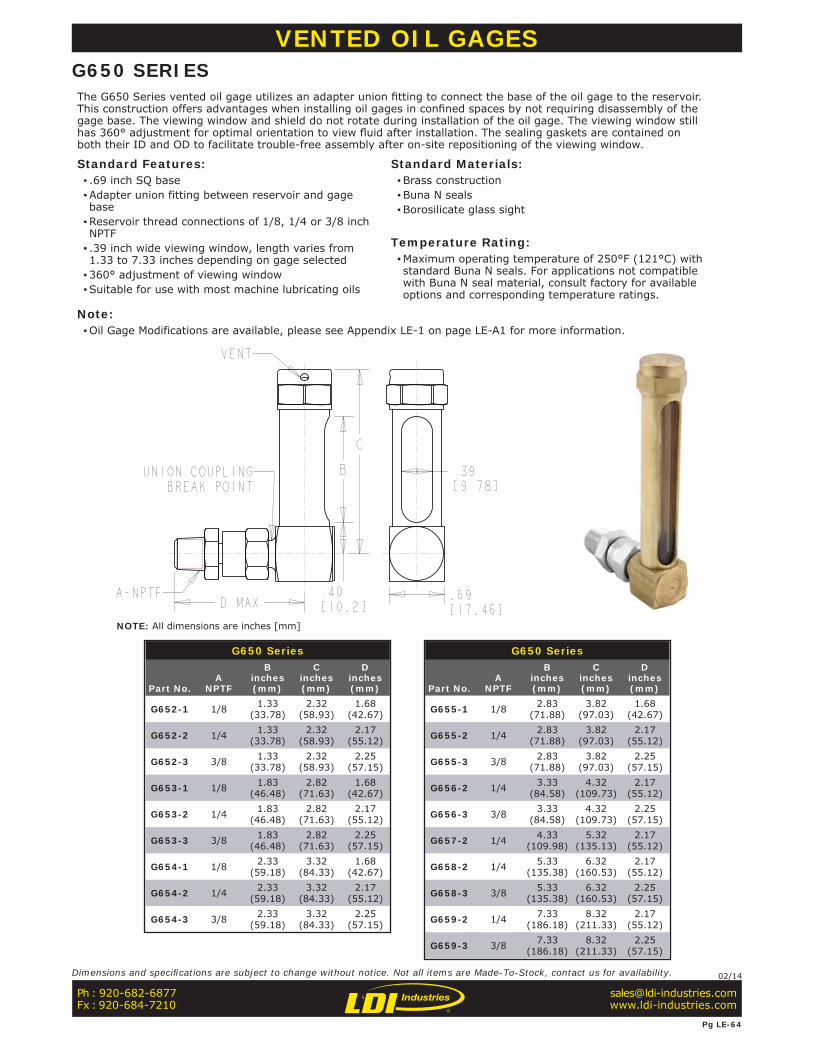
G650 Series
Part No.A
NPTF
Binches(mm)
Cinches(mm)
Dinches(mm)
G652-1 1/8 1.33(33.78)
2.32(58.93)
1.68(42.67)
G652-2 1/4 1.33(33.78)
2.32(58.93)
2.17(55.12)
G652-3 3/8 1.33(33.78)
2.32(58.93)
2.25(57.15)
G653-1 1/8 1.83(46.48)
2.82(71.63)
1.68(42.67)
G653-2 1/4 1.83(46.48)
2.82(71.63)
2.17(55.12)
G653-3 3/8 1.83(46.48)
2.82(71.63)
2.25(57.15)
G654-1 1/8 2.33(59.18)
3.32(84.33)
1.68(42.67)
G654-2 1/4 2.33(59.18)
3.32(84.33)
2.17(55.12)
G654-3 3/8 2.33(59.18)
3.32(84.33)
2.25(57.15)
G650 Series
Part No.A
NPTF
Binches(mm)
Cinches(mm)
Dinches(mm)
G655-1 1/8 2.83(71.88)
3.82(97.03)
1.68(42.67)
G655-2 1/4 2.83(71.88)
3.82(97.03)
2.17(55.12)
G655-3 3/8 2.83(71.88)
3.82(97.03)
2.25(57.15)
G656-2 1/4 3.33(84.58)
4.32(109.73)
2.17(55.12)
G656-3 3/8 3.33(84.58)
4.32(109.73)
2.25(57.15)
G657-2 1/4 4.33(109.98)
5.32(135.13)
2.17(55.12)
G658-2 1/4 5.33(135.38)
6.32(160.53)
2.17(55.12)
G658-3 3/8 5.33(135.38)
6.32(160.53)
2.25(57.15)
G659-2 1/4 7.33(186.18)
8.32(211.33)
2.17(55.12)
G659-3 3/8 7.33(186.18)
8.32(211.33)
2.25(57.15)
VENTED OIL GAGESG650 SERIESThe G650 Series vented oil gage utilizes an adapter union fi tting to connect the base of the oil gage to the reservoir. This construction offers advantages when installing oil gages in confi ned spaces by not requiring disassembly of the gage base. The viewing window and shield do not rotate during installation of the oil gage. The viewing window still has 360° adjustment for optimal orientation to view fl uid after installation. The sealing gaskets are contained on both their ID and OD to facilitate trouble-free assembly after on-site repositioning of the viewing window.
Standard Features: ▪ .69 inch SQ base ▪Adapter union fitting between reservoir and gage base ▪Reservoir thread connections of 1/8, 1/4 or 3/8 inch NPTF ▪ .39 inch wide viewing window, length varies from 1.33 to 7.33 inches depending on gage selected ▪360° adjustment of viewing window ▪Suitable for use with most machine lubricating oils
Standard Materials: ▪Brass construction ▪Buna N seals ▪Borosilicate glass sight
Temperature Rating: ▪Maximum operating temperature of 250°F (121°C) with standard Buna N seals. For applications not compatible with Buna N seal material, consult factory for available options and corresponding temperature ratings.
Note: ▪Oil Gage Modifications are available, please see Appendix LE-1 on page LE-A1 for more information.
NOTE: All dimensions are inches [mm]
Ph : 920-682-6877Fx : 920-684-7210
Pg LE-64
Dimensions and specifi cations are subject to change without notice. Not all items are Made-To-Stock, contact us for availability. 02/14
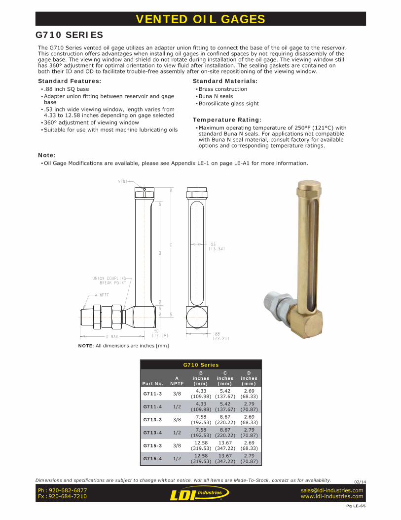
G710 Series
Part No.A
NPTF
Binches(mm)
Cinches(mm)
Dinches(mm)
G711-3 3/8 4.33(109.98)
5.42(137.67)
2.69(68.33)
G711-4 1/2 4.33(109.98)
5.42(137.67)
2.79(70.87)
G713-3 3/8 7.58(192.53)
8.67(220.22)
2.69(68.33)
G713-4 1/2 7.58(192.53)
8.67(220.22)
2.79(70.87)
G715-3 3/8 12.58(319.53)
13.67(347.22)
2.69(68.33)
G715-4 1/2 12.58(319.53)
13.67(347.22)
2.79(70.87)
VENTED OIL GAGESG710 SERIESThe G710 Series vented oil gage utilizes an adapter union fi tting to connect the base of the oil gage to the reservoir. This construction offers advantages when installing oil gages in confi ned spaces by not requiring disassembly of the gage base. The viewing window and shield do not rotate during installation of the oil gage. The viewing window still has 360° adjustment for optimal orientation to view fl uid after installation. The sealing gaskets are contained on both their ID and OD to facilitate trouble-free assembly after on-site repositioning of the viewing window.
Standard Features: ▪ .88 inch SQ base ▪Adapter union fitting between reservoir and gage base ▪ .53 inch wide viewing window, length varies from 4.33 to 12.58 inches depending on gage selected ▪360° adjustment of viewing window ▪Suitable for use with most machine lubricating oils
Standard Materials: ▪Brass construction ▪Buna N seals ▪Borosilicate glass sight
Temperature Rating: ▪Maximum operating temperature of 250°F (121°C) with standard Buna N seals. For applications not compatible with Buna N seal material, consult factory for available options and corresponding temperature ratings.
Note: ▪Oil Gage Modifications are available, please see Appendix LE-1 on page LE-A1 for more information.
NOTE: All dimensions are inches [mm]
Ph : 920-682-6877Fx : 920-684-7210
Pg LE-65
Dimensions and specifi cations are subject to change without notice. Not all items are Made-To-Stock, contact us for availability. 02/14
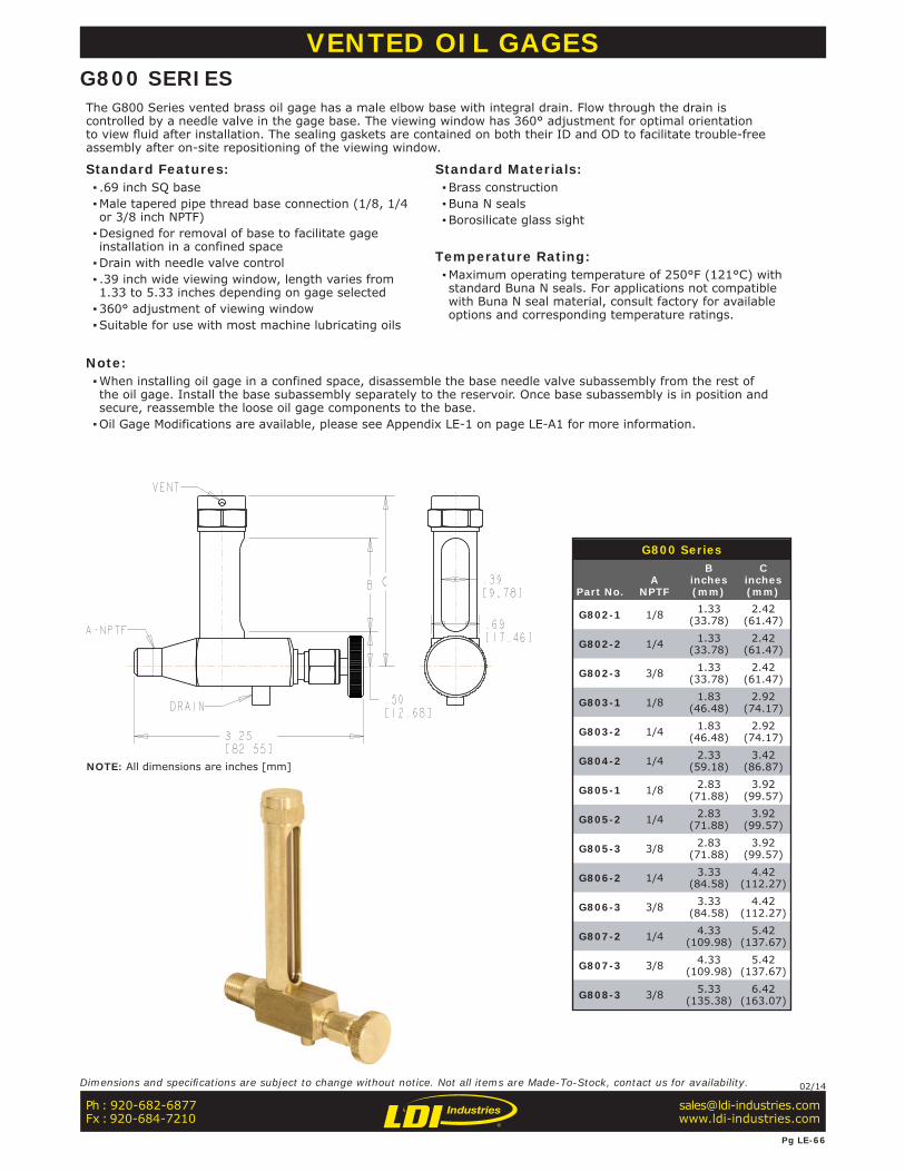
G800 Series
Part No.A
NPTF
Binches(mm)
Cinches(mm)
G802-1 1/8 1.33(33.78)
2.42(61.47)
G802-2 1/4 1.33(33.78)
2.42(61.47)
G802-3 3/8 1.33(33.78)
2.42(61.47)
G803-1 1/8 1.83(46.48)
2.92(74.17)
G803-2 1/4 1.83(46.48)
2.92(74.17)
G804-2 1/4 2.33(59.18)
3.42(86.87)
G805-1 1/8 2.83(71.88)
3.92(99.57)
G805-2 1/4 2.83(71.88)
3.92(99.57)
G805-3 3/8 2.83(71.88)
3.92(99.57)
G806-2 1/4 3.33(84.58)
4.42(112.27)
G806-3 3/8 3.33(84.58)
4.42(112.27)
G807-2 1/4 4.33(109.98)
5.42(137.67)
G807-3 3/8 4.33(109.98)
5.42(137.67)
G808-3 3/8 5.33(135.38)
6.42(163.07)
VENTED OIL GAGESG800 SERIESThe G800 Series vented brass oil gage has a male elbow base with integral drain. Flow through the drain is controlled by a needle valve in the gage base. The viewing window has 360° adjustment for optimal orientation to view fl uid after installation. The sealing gaskets are contained on both their ID and OD to facilitate trouble-free assembly after on-site repositioning of the viewing window.
Standard Features: ▪ .69 inch SQ base ▪Male tapered pipe thread base connection (1/8, 1/4 or 3/8 inch NPTF) ▪Designed for removal of base to facilitate gage installation in a confined space ▪Drain with needle valve control ▪ .39 inch wide viewing window, length varies from 1.33 to 5.33 inches depending on gage selected ▪360° adjustment of viewing window ▪Suitable for use with most machine lubricating oils
Standard Materials: ▪Brass construction ▪Buna N seals ▪Borosilicate glass sight
Temperature Rating: ▪Maximum operating temperature of 250°F (121°C) with standard Buna N seals. For applications not compatible with Buna N seal material, consult factory for available options and corresponding temperature ratings.
Note: ▪When installing oil gage in a confined space, disassemble the base needle valve subassembly from the rest of the oil gage. Install the base subassembly separately to the reservoir. Once base subassembly is in position and secure, reassemble the loose oil gage components to the base. ▪Oil Gage Modifications are available, please see Appendix LE-1 on page LE-A1 for more information.
NOTE: All dimensions are inches [mm]
Ph : 920-682-6877Fx : 920-684-7210
Pg LE-66
Dimensions and specifi cations are subject to change without notice. Not all items are Made-To-Stock, contact us for availability. 02/14

G900 Series
Part No.A
NPTF
Binches(mm)
Cinches(mm)
G901-3 3/8 4.33(109.98)
5.48(139.19)
G901-4 1/2 4.33(109.98)
5.48(139.19)
G903-3 3/8 7.58(192.53)
8.73(221.74)
G903-4 1/2 7.58(192.53)
8.73(221.74)
G905-3 3/8 12.58(319.53)
13.73(348.74)
G905-4 1/2 12.58(319.53)
13.73(348.74)
VENTED OIL GAGESG900 SERIESThe G900 Series vented brass oil gage with male elbow base with integral drain. Flow through the drain is controlled by a needle valve in the gage base. Thread options include 3/8 or 1/2 NPTF threads. The viewing window has 360° adjustment for optimal orientation to view fl uid after installation. The sealing gaskets are contained on both their ID and OD to facilitate trouble-free assembly after on-site repositioning of the viewing window.
Standard Features: ▪ .88 inch SQ base ▪Male tapered pipe thread base connection (3/8 or 1/2 inch NPTF) ▪Designed for removal of base to facilitate gage installation in a confined space ▪Drain with needle valve control ▪ .53 inch wide viewing window, length varies from 4.33 to 12.58 inches depending on gage selected ▪360° adjustment of viewing window ▪Suitable for use with most machine lubricating oils
Standard Materials: ▪Brass construction ▪Buna N seals ▪Borosilicate glass sight
Temperature Rating: ▪Maximum operating temperature of 250°F (121°C) with standard Buna N seals. For applications not compatible with Buna N seal material, consult factory for available options and corresponding temperature ratings.
Notes: ▪When installing oil gage in a confined space, disassemble the base needle valve subassembly from the rest of the oil gage. Install the base subassembly separately to the reservoir. Once base subassembly is in position and secure, reassemble the loose oil gage components to the base. ▪Oil Gage Modifications are available, please see Appendix LE-1 on page LE-A1 for more information.
NOTE: All dimensions are inches [mm]
Ph : 920-682-6877Fx : 920-684-7210
Pg LE-67
Dimensions and specifi cations are subject to change without notice. Not all items are Made-To-Stock, contact us for availability. 02/14
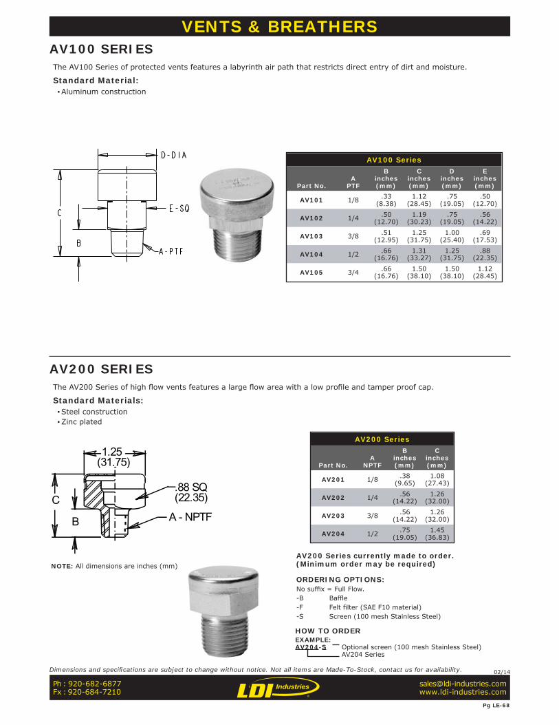
VENTS & BREATHERSAV100 SERIESThe AV100 Series of protected vents features a labyrinth air path that restricts direct entry of dirt and moisture.
Standard Material: ▪Aluminum construction
AV100 Series
Part No.A
PTF
Binches(mm)
Cinches(mm)
Dinches(mm)
Einches(mm)
AV101 1/8 .33(8.38)
1.12(28.45)
.75(19.05)
.50(12.70)
AV102 1/4 .50(12.70)
1.19(30.23)
.75(19.05)
.56(14.22)
AV103 3/8 .51(12.95)
1.25(31.75)
1.00(25.40)
.69(17.53)
AV104 1/2 .66(16.76)
1.31(33.27)
1.25(31.75)
.88(22.35)
AV105 3/4 .66(16.76)
1.50(38.10)
1.50(38.10)
1.12(28.45)
The AV200 Series of high fl ow vents features a large fl ow area with a low profi le and tamper proof cap.
Standard Materials: ▪Steel construction ▪Zinc plated
.88 SQ
A - NPTFC
B
1.25(31.75)
(22.35)
AV200 Series
Part No.A
NPTF
Binches(mm)
Cinches(mm)
AV201 1/8 .38(9.65)
1.08(27.43)
AV202 1/4 .56(14.22)
1.26(32.00)
AV203 3/8 .56(14.22)
1.26(32.00)
AV204 1/2 .75(19.05)
1.45(36.83)
AV200 Series currently made to order.(Minimum order may be required)
ORDERING OPTIONS:No suffi x = Full Flow.-B Baffl e-F Felt fi lter (SAE F10 material)-S Screen (100 mesh Stainless Steel)
HOW TO ORDEREXAMPLE:AV204-S Optional screen (100 mesh Stainless Steel)
AV204 Series
AV200 SERIES
Ph : 920-682-6877Fx : 920-684-7210
Pg LE-68
Dimensions and specifi cations are subject to change without notice. Not all items are Made-To-Stock, contact us for availability. 02/14
NOTE: All dimensions are inches (mm)
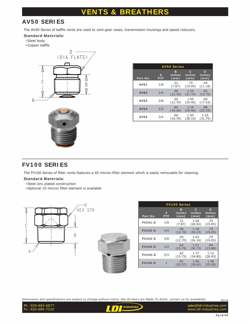
VENTS & BREATHERSAV50 SERIESThe AV50 Series of baffl e vents are used to vent gear cases, transmission housings and speed reducers.
Standard Materials: ▪Steel body ▪Copper baffle
AV50 Series
Part No.A
PTF
Binches(mm)
Cinches(mm)
Dinches(mm)
AV51 1/8 .31(7.87)
.75(19.05)
.44(11.18)
AV52 1/4 .50(12.70)
1.25(31.75)
.62(15.75)
AV53 3/8 .50(12.70)
1.00(25.40)
.69(17.53)
AV54 1/2 .64(16.26)
1.16(29.46)
.88(22.35)
AV55 3/4 .66(16.76)
1.50(38.10)
1.25(31.75)
FV100 Series
Part No.A
PTF
Binches(mm)
Cinches(mm)
Dinches(mm)
FV101-S 1/8 .31(7.87)
1.06(26.92)
.75(19.05)
FV102-S 1/4 .50(12.70)
1.19(30.23)
.75(19.05)
FV103-S 3/8 .50(12.70)
1.03(26.16)
.75(19.05)
FV104-S 1/2 .62(15.75)
1.21(30.73)
.94(23.88)
FV105-S 3/4 .62(15.75)
1.37(34.80)
1.12(28.45)
FV106-S 1 .81(20.57)
1.56(39.62)
1.38(35.05)
FV100 SERIESThe FV100 Series of fi lter vents features a 40 micron fi lter element which is easily removable for cleaning.
Standard Materials: ▪Steel zinc plated construction ▪Optional 10 micron filter element is available
Ph : 920-682-6877Fx : 920-684-7210
Pg LE-69
Dimensions and specifi cations are subject to change without notice. Not all items are Made-To-Stock, contact us for availability. 05/16
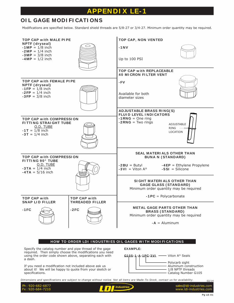
APPENDICESAPPENDIX LE-1 OIL GAGE MODIFICATIONS
HOW TO ORDER LDI INDUSTRIES OIL GAGES WITH MODIFICATIONS
Specify the catalog number and pipe thread of the gage required. Then simply choose the modifi cations you need using the order code shown above, separating each with a dash.
If you need a modifi cation not included above ask us about it! We will be happy to quote from your sketch or specifi cations.
EXAMPLE:
G105-1-A-1PC-3VI Viton A® Seals
Polycarb sightAluminum construction1/8 NPTF threadsCatalog Number G105
Modifi cations are specifi ed below. Standard shield threads are 5/8-27 or 3/4-27. Minimum order quantity may be required.
TOP CAP with MALE PIPENPTF (dryseal)-1MP = 1/8 inch-2MP = 1/4 inch-3MP = 3/8 inch-4MP = 1/2 inch
TOP CAP with FEMALE PIPENPTF (dryseal)-1FP = 1/8 inch-2FP = 1/4 inch-3FP = 3/8 inch
TOP CAP with COMPRESSIONFITTING STRAIGHT TUBE O.D. TUBE-1T = 1/8 inch-3T = 1/4 inch
TOP CAP with COMPRESSIONFITTING 90° TUBE O.D. TUBE-3TA = 1/4 inch-4TA = 5/16 inch
TOP CAP withSNAP LID FILLER
-1FC
TOP CAP withTHREADED FILLER
-2FC
TOP CAP, NON VENTED
-1NV
Up to 100 PSI
TOP CAP with REPLACEABLE40 MICRON FILTER VENT
-FV
Available for bothdiameter sizes
ADJUSTABLE BRASS RING(S)FLUID LEVEL INDICATORS-1RNG = One ring-2RNG = Two rings
SEAL MATERIALS OTHER THANBUNA N (STANDARD)
-2BU = Butyl-3VI = Viton A®
-4EP = Ethylene Propylene-5SI = Silicone
SIGHT MATERIALS OTHER THANGAGE GLASS (STANDARD)
Minimum order quantity may be required
-1PC = Polycarbonate
METAL GAGE PARTS OTHER THANBRASS (STANDARD)
Minimum order quantity may be required
-A = Aluminum
Ph : 920-682-6877Fx : 920-684-7210
Pg LE-A1
Dimensions and specifi cations are subject to change without notice. Not all items are Made-To-Stock, contact us for availability. 02/14
ADJUSTABLERINGLOCATION
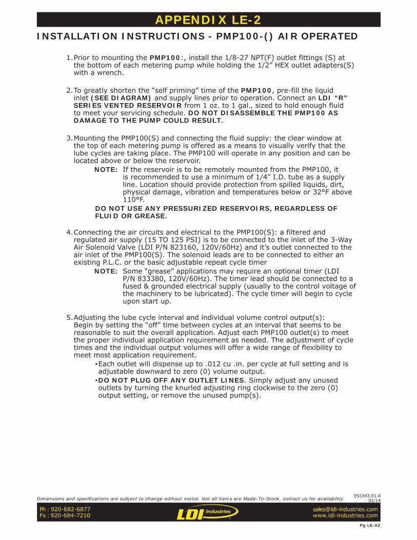
APPENDIX LE-2 INSTALLATION INSTRUCTIONS - PMP100-() AIR OPERATED
1. Prior to mounting the PMP100:, install the 1/8-27 NPT(F) outlet fittings (S) at the bottom of each metering pump while holding the 1/2” HEX outlet adapters(S) with a wrench.
2. To greatly shorten the “self priming” time of the PMP100, pre-fill the liquid inlet (SEE DIAGRAM) and supply lines prior to operation. Connect an LDI “R” SERIES VENTED RESERVOIR from 1 oz. to 1 gal., sized to hold enough fluid to meet your servicing schedule. DO NOT DISASSEMBLE THE PMP100 AS DAMAGE TO THE PUMP COULD RESULT.
3. Mounting the PMP100(S) and connecting the fluid supply: the clear window at the top of each metering pump is offered as a means to visually verify that the lube cycles are taking place. The PMP100 will operate in any position and can be located above or below the reservoir.
NOTE: If the reservoir is to be remotely mounted from the PMP100, it is recommended to use a minimum of 1/4” I.D. tube as a supply line. Location should provide protection from spilled liquids, dirt, physical damage, vibration and temperatures below or 32°F above 110°F.
DO NOT USE ANY PRESSURIZED RESERVOIRS, REGARDLESS OF FLUID OR GREASE.
4. Connecting the air circuits and electrical to the PMP100(S): a filtered and regulated air supply (15 TO 125 PSI) is to be connected to the inlet of the 3-Way Air Solenoid Valve (LDI P/N 823160, 120V/60Hz) and it’s outlet connected to the air inlet of the PMP100(S). The solenoid leads are to be connected to either an existing P.L.C. or the basic adjustable repeat cycle timer
NOTE: Some “grease” applications may require an optional timer (LDI P/N 833380, 120V/60Hz). The timer lead should be connected to a fused & grounded electrical supply (usually to the control voltage of the machinery to be lubricated). The cycle timer will begin to cycle upon start up.
5. Adjusting the lube cycle interval and individual volume control output(s): Begin by setting the “off” time between cycles at an interval that seems to be reasonable to suit the overall application. Adjust each PMP100 outlet(s) to meet the proper individual application requirement as needed. The adjustment of cycle times and the individual output volumes will offer a wide range of flexibility to meet most application requirement.
▪Each outlet will dispense up to .012 cu .in. per cycle at full setting and is adjustable downward to zero (0) volume output. ▪DO NOT PLUG OFF ANY OUTLET LINES. Simply adjust any unused outlets by turning the knurled adjusting ring clockwise to the zero (0) output setting, or remove the unused pump(s).
Ph : 920-682-6877Fx : 920-684-7210
Pg LE-A2
Dimensions and specifi cations are subject to change without notice. Not all items are Made-To-Stock, contact us for availability. ES1043.01.A02/14
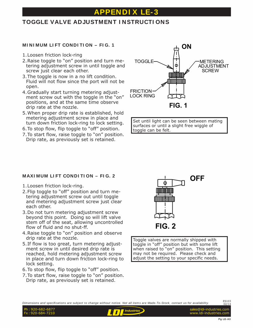
APPENDIX LE-3 TOGGLE VALVE ADJUSTMENT INSTRUCTIONS
MINIMUM LIFT CONDITION – FIG. 1
1. Loosen friction lock-ring2. Raise toggle to “on” position and turn me-
tering adjustment screw in until toggle and screw just clear each other.
3. The toggle is now in a no lift condition. Fluid will not flow since the port will not be open.
4. Gradually start turning metering adjust-ment screw out with the toggle in the “on” positions, and at the same time observe drip rate at the nozzle.
5. When proper drip rate is established, hold metering adjustment screw in place and turn down friction lock-ring to lock setting.
6. To stop flow, flip toggle to “off” position.7. To start flow, raise toggle to “on” position.
Drip rate, as previously set is retained.
MAXIMUM LIFT CONDITION – FIG. 2
1. Loosen friction lock-ring.2. Flip toggle to “off” position and turn me-
tering adjustment screw out until toggle and metering adjustment screw just clear each other.
3. Do not turn metering adjustment screw beyond this point. Doing so will lift valve stem off of the seat, allowing uncontrolled flow of fluid and no shut-ff.
4. Raise toggle to “on” position and observe drip rate at the nozzle.
5. If flow is too great, turn metering adjust-ment screw in until desired drip rate is reached, hold metering adjustment screw in place and turn down friction lock-ring to lock setting.
6. To stop flow, flip toggle to “off” position.7. To start flow, raise toggle to “on” position.
Drip rate, as previously set is retained.
METERINGADJUSTMENT
SCREW
ON
FRICTIONLOCK RING
TOGGLE
FIG. 1
OFF
FIG. 2
Set until light can be seen between mating surfaces or until a slight free wiggle of toggle can be felt.
Toggle valves are normally shipped with toggle in “off” position but with some lift when raised to “on” position. This setting may not be required. Please check and adjust the setting to your specifi c needs.
Ph : 920-682-6877Fx : 920-684-7210
Pg LE-A3
Dimensions and specifi cations are subject to change without notice. Not all items are Made-To-Stock, contact us for availability. ES10302/14