A Presentation on Cascadable Adiabatic Logic Circuits for Low-Power applications By Divya Yashwanth.
Upload
esmond-knightCategory
view
214download
0
Low Power Designand
Adiabatic Circuits
P.Ranjith
M.Tech(ICT)
200611021

Why low power?
• Desirability of portable devices.
• Advent of hand held battery operated devices.
• Large power dissipation requires larger heat sinks hence increased area.
• Cost of providing power has resulted in significant interest in power reduction of non portable devices

Components of Power
• Dynamic– Signal transitions
• Logic activity• Glitches
– Short-circuit
• Static– Leakage

Power Dissipation in CMOS Logic (0.25µ)
%75 %5%20
CL
Ptotal (0→1) = CL VDD2 + tscVDD Ipeak + VDDleakage
lecture slide of Vishwani D. Agrawal of Auburn University

Components of power dissipation

VVDDDD
GroundGround
C
R
R
Power
= CVDD2/2
Power of a Transition

Ways to reduce dynamic power
• Reduce supply voltage (vdd) it has a quadratic relationship with power.
• Decrease physical capacitance (interconnect, proper placement&routing, device capacitance )
• Reduce activity (reduce glitches)
• Reduce rise time and fall time

Limitations to above approaches
• Reduction of Vdd with out correspondingly reducing Vt reduces speed drastically and Vdd must be at least 2Vt.
• Issues of compatibility
• Reduction in physical capacitance by reducing sizes of devices reduces driving capability hence speed

1/2 cv2 necessary?
• After 3RC output is 95% of final value energy dissipation is almost 97.5% of final value
• Use two power supplies one at v/2 other v
for the first 3RC use v/2 source next 3RC use v this is called step-wise charging
energy dissipation reduces by half !!!!!!!

• Stretch the transition time by a factor n keeping maximum voltage drop to v/n energy scales by a factor n
• Continuously vary input voltage v so that current remains constant
i(t)=Q/T=CV/T
Ediss = R 0∫t i2(t) dt=RC/T CV2

Introduction to adiabatic circuits
• Thermodynamic meaning: no heat transfer.
• Instead of dissipating power reuse it.
• By externally controlling the length and shape of signal transitions energy spent to flip a bit can be reduced to very small values

Common rules to be followed
• Never use diodes since they are fundamentally thermodynamically irreversible
• Do not turn on the MOSFET when there is signficant potential difference between source and drain
• Do not turnoff when there is a significant current flowing through the device

Types of adiabatic logic families
• Fully adiabatic families Split Level Charge Recovery logic Reversible Energy Recovery Logic • Quasi adiabatic families Pass-transistor Adiabatic Logic Latched Pass-transistor Adiabatic Logic 2N-2P Family 2N-2N2P Family
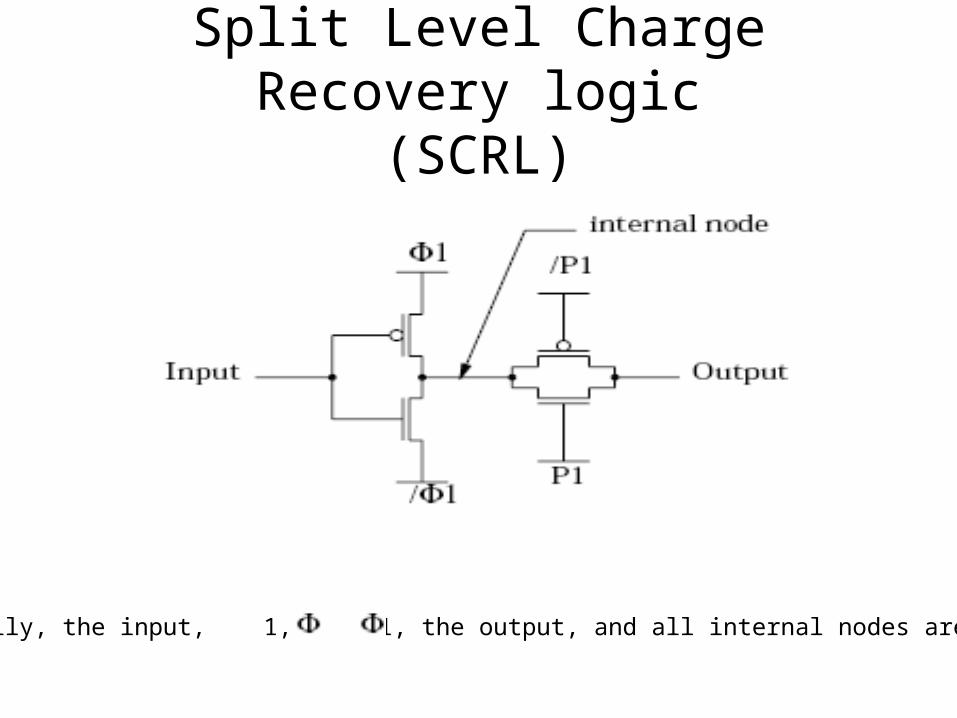
Split Level Charge Recovery logic(SCRL)
Initially, the input, 1, / 1, the output, and all internal nodes are at Vdd/2.

SCRL (cont.)
• Forbid turning on of a device when there is a potential difference.
• Once the device is on energy transfer takes place in a controlled manner so that
no potential drop across the device

Non-dissipative multi-stage pipeline connection
SCRL pipeline

Non-Inverting SCRL Gate

Ways to reduce reversibility cost
• Providing inverse of a function is cumbersome sometimes
• Gates that computed the inverse function of the gates in the forward direction produce a correct copy of the inputs all the time. Without these inverse gates, we cannot guarantee to be correct all the time. In certain applications however, we can guarantee to be correct most of the time.
• Consider nand gate output is mostly true hence instead of inverse connect false output directly.

2N-2P Family

Timing diagram for 2N-2P family
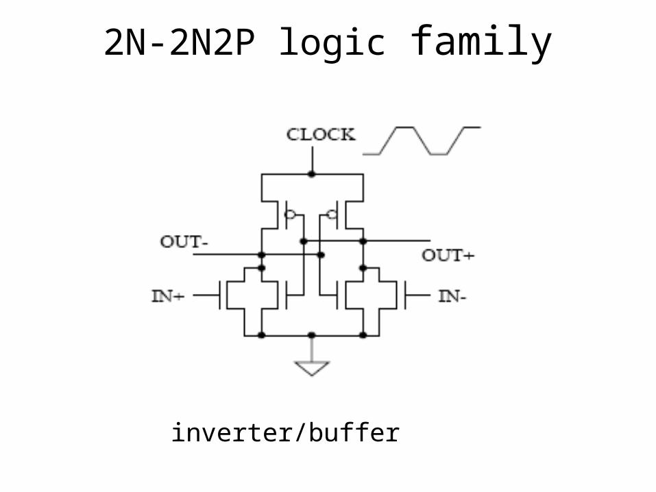
2N-2N2P logic family
inverter/buffer

2N-2N2P logic family(contd.)
Complex gate

Conclusions
• Adiabatic design is an energy efficient way of design for low power circuits
• Asymptotically zero energy can be obtained by using fully adiabatic circuits at the cost of complexity.
• Quasi adiabatic logics can be used with minimum energy loss and less complexity.

References
• S. G. Younis and T. Knight, Practical Implementation of Charge Recovering Asymptotically Zero Power CMOS", Proc. of 1993 Symposium on Integrated Systems, 234-250. MIT Press (1993).
• A. G. Dickinson and J. S. Denker, Adiabatic Dynamic Logic", Proceedings of the Custom Integrated Circuits Conference. IEEE (1994).
• low power design methodologies Jan.M.Rabey and Massoud Pedram Kluwer academic publishers
• A. G. Dickinson and J. S. Denker, “Adiabatic dynamic logic”,
IEEEJ. Solid-State Circuits, Vol. 30, pp. 311-315, March 1995.