Andy Evans Programme Director, Connected Nottinghamshire Information sharing – the complete picture.
Low-Latency High-Level Data Sharing forConnected and Autonomous Vehicular Networks
Qi Chen∗, Sihai Tang∗, Jacob Hochstetler∗, Jingda Guo∗, Yuan Li∗, Jinbo Xiong†, Qing Yang∗, Song Fu∗∗Department of Computer Science and Engineering, University of North Texas, USA†College of Mathematics and Informatics, Fujian Normal University, China
{QiChen, SihaiTang, JacobHochstetler, JingdaGuo, YuanLi4}@my.unt.edu {Jinbo.Xiong, Qing.Yang, Song.Fu}@unt.edu
Abstract—Autonomous vehicles can combine their own datawith that of other vehicles to enhance their perceptive ability,and thus improve detection accuracy and driving safety. Datasharing among autonomous vehicles, however, is a challengingproblem due to the sheer volume of data generated by varioustypes of sensors on the vehicles. In this paper, we propose alow-latency, high-level (L3) data sharing protocol for connectedand autonomous vehicular networks. Based on the L3 protocol,sensing results generated by individual vehicles will be broad-casted simultaneously within a limited sensing zone. The L3protocol reduces the networking latency by taking advantage ofthe capture effect of the wireless transmissions occurred amongvehicles. With the proposed design principles, we implement andtest the L3 protocol in a simulated environment. Simulationresults demonstrate that the L3 protocol is able to achieve reliableand fast data sharing among autonomous vehicles.
Keywords—Low latency, data sharing, object detection, captureeffect, autonomous and connected vehicles
I. INTRODUCTION
For years, the development of connected and autonomousvehicles (CAV) technology has garnered significant interestfrom both research institutes and industry alike. CAV incorpo-rate a variety of different technologies, ranging from computervision [9] to wireless networking [23], to facilitate a safeand efficient movement of people and goods, revolutionizingthe current transportation system. It brings a host of benefitssuch as improved safety, convenient mobility for the elderlyand disabled, and a better public transportation system [10].Ideally, CAV could help drive fatalities to near zero, given thetechnologies continue to improve.
Autonomous vehicles are typically equipped with high-precision sensing systems, producing a healthy amount ofsensor data that need to be processed in real time. Forexample, the autonomous vehicles developed by companiessuch as Google, Tesla, Mobileye autopilot systems, are mainlyequipped with LiDAR (light detection and ranging), camera,Radar, ultrasound, thermal camera, GPS, and IMU (inertialmeasurement unit ), etc. Currently, the data generated bythese sensors are processed and stored locally on individualvehicles, and rarely shared among autonomous vehicles. Thecurrent solutions, however, come with several limitations.When driving in the evening, rain, snow, fog or other badweather conditions, cameras may not work properly. Similarlywith LiDAR and Radar sensors, intersections, turning cornersand other scenarios may witness the sensing systems not
functioning properly. For example, Tesla autonomous car oncehad a fatal accident on a freeway. The vehicle failed to identifythe white body of a truck under an intense sunshine condition,and therefore did not activate the brake system in time. Whiledeveloping more powerful sensors may solve these issues, theassociated cost will rise to the point where consumers cannotafford the product, i.e., individual customers aren’t likely tosee such vehicles in much volume.
A possible solution to the above mentioned issues is toallow autonomous vehicles to exchange real-time sensingdata to each other, realizing a connected and autonomousvehicular system. Although data sharing among vehicles ispromising, it faces several challenges that must be adequatelyaddressed before the technology is deployed in real world.These challenges are related to both data processing and datasharing, e.g., it is difficult to synchronize the sensing dataamong vehicles, the networking bandwidth of existing wirelesstechnologies is too limited to transmit the data, the largenetworking delay may be prohibitive for autonomous drivingapplications. In summary, without efficient data processing andtransmission mechanisms, the sheer amount of resources thatwill be consumed by autonomous vehicles can dramaticallyslow the deployment of CAV technologies.
A. Motivations
To achieve data sharing among autonomous vehicles, aneffective way is to adopt the V2X communications [25]. Intu-itively, V2X communication connects cars to other cars or theInternet to form a vehicular networks, including V2V (vehicleto vehicle), V2I (vehicle to infrastructure), V2N (vehicle toInternet) and V2P (vehicle to people) communications. V2Xcommunication can be viewed as a means that allows thesensors on vehicles to extend their sensing range well beyondwhat they are physically capable of. By sharing the sensingresults with nearby vehicles and roadside infrastructures, ve-hicles can greatly enhance the perception of the surroundingenvironment and thus enhancing their decision making. Eventhough the self-driving function can be partially achieved bythe vehicle itself, using V2X can further improve safety anddriving performance by reducing the cost of deploying high-precision sensors. In addition to improving its own perceptionand decision making, the enabled autonomous vehicle can alsoimprove the driving reliability for the normal human operated
arX
iv:1
912.
0108
0v1
[cs
.NI]
2 D
ec 2
019

vehicles, making it more encouraging for the adoption of morevehicles equipping V2X devices.
B. Challenges
The challenge of a CAV system comes from the massivedeployment of sensors on the autonomous vehicles and thehuge amount of data that they can pick up from the environ-ment [26]. First of all, it is challenging to synchronize andfuse data generated from different vehicles which may usedifferent sensors (and algorithms) to perceive the surroundingenvironment. Data fusion is the process of combining multiplevehicles’ data to produce a more consistent, accurate, andreliable perception than what is offered by an individual vehi-cle [11]. The data fusion process in CAV is usually classifiedinto three categories: low-level, intermediate-level, and high-level fusions, depending on the processing stage at which thefusion takes place [16]. As their names imply, low-level fusionrefers to raw data fusion, which requires the highest networkbandwidth to transmit the data. Intermediate-level fusion, suchas feature-based fusion, takes the features extracted from theraw data before fusion. Finally, high-level fusion takes theprocessing results, e.g., the objects detected from cameras, toconduct the fusion. For wireless vehicular networks, regardlesswhich type of fusion is adopted, the large amount of datagenerated and shared among vehicles will pose significantresearch challenges to existing wireless technologies, e.g.,dedicated shorte range communication (DSRC) [15] and 5Gnetworks.
C. Proposed Solution
To facilitate data sharing among autonomous vehicles, high-level fusion is often opted over the other two levels of fusion,due to the small amount of data exchanged between vehicles.In this way, each vehicle processes its sensing data locallyand exchange its sensing results with nearby vehicles. Aslong as the format of the sensing results are standardized, itdoes not matter what sensing technologies individual vehiclesadopt. In this paper, we focus on the object detection resultsgenerated by the perception system on autonomous vehicles.The object detection function is itself one of key componentsfor autonomous vehicles, as it allows a vehicle to accountfor obstacles when considering possible moving trajectories.The object detection results of a vehicle are represented in asensing matrix, which provides an overview of objects existingin the vehicle’s surrounding environment. Each vehicle willbroadcast its sensing matrix to nearby vehicles to achievea high-level data sharing in CAV systems. To mitigate thepotential collision of packets simultaneously transmitted bymultiple vehicles, a low-latency data sharing mechanism isdesigned, leveraging the capture effect that is widely observedin various wireless communication techniques. With the abovedesign principles, we propose a Low-Latency and high-Level(L3) data sharing protocol for connected and autonomousvehicles.
D. Contributions
Inaccurate object detection and recognition are major im-pediments in achieving a powerful and effective perceptionsystem on autonomous vehicles. To address these issues, wepropose the L3 protocol in which an autonomous vehiclecombines its own sensing data with that of other vehiclesto help enhance its own perception. We believe that dataredundancy, as mentioned, is the solution to this problemand we can achieve it through data sharing and combinationbetween autonomous vehicles. The L3 protocol is effectiveand efficient, which can improve the detection performanceand driving experience thus providing better safety. Specifi-cally, we make the following contributions. We propose themechanism to divide a digital map into sensing zone andvehicles will only exchange sensing data about one zone inwhich it current resides, leading to scalable data sharing. Theobject detection results on each vehicle are represented in asensing matrix, which facilitates a quick information sharingamong vehicle, leveraging the capture effect. The proposedL3 protocol is evaluated in simulations and it significantlyoutperforms existing solutions, i.e., offering a lower networklatency in sharing data among vehicles.
II. DATA SHARING FOR CONNECTED AND AUTONOMOUSVEHICLES
To design an efficient data sharing protocol for connectedautonomous vehicle, it is necessary to first understand the char-acteristics of data produced by various sensors on autonomousvehicles. In this section, we investigate the mismatch betweenthe huge amount of data generated from autonomous vehiclesand the limited network bandwidth available for vehicularcommunications.
A. Characteristics of Data on Autonomous Vehicles
Autonomous vehicle is typically equipped with varioustypes of sensors to obtain fine-grained, real-time and accurateinformation about its surrounding driving environments. Theperception system on an autonomous vehicle usually consistsof several LiDAR, Radar, camera sensors, ultrasonic sensors,GPS and IMU (inertial measurement unit) sensors. Throughthese sensors, sheer amount of data will be generated and thesedata must be processed in real time. Each autonomous vehiclewill collect almost 4,000 Gigabyte data per day, accordingto [21]. A LiDAR sensor, e.g., Velodyne LiDAR HDL-64,will generate 9.75 Mbps data when it scans at 5Hz, and up to39 Mbps at 20Hz.
LiDAR is an essential component for autonomous vehiclesas as it is used to detect dynamic and static objects includingother cars or pedestrians in order to navigate around them. Li-DAR is also applied to create high-definition maps and achievehigh-accuracy localization of autonomous vehicles. Due tothe popularity of installing LiDAR sensors on autonomousvehicles, in this paper, we use the point cloud data generatedby LiDAR as a case study to illustrate how the proposed L3protocol works for connected and autonomous vehicles.

To process the data generated by LiDAR sensors, severalmethods are proposed, e.g., MV3D [6] and VoxelNet [27], todetect the objects existing in point cloud data. Due to the spar-sity of LiDAR data, it is quite challenging to accurately detectall objects in point cloud data. Recently, VoxelNet [27] hasannounced its experiments on the KITTI dataset, i.e., it offersan acceptable object detection performance on LiDAR data.However, its detection accuracy is far from the performance ofcamera-based solutions. The average car detection precision ofVoxelNet is only 81.97%. For smaller objects, e.g., pedestrianand cyclist, its average precision drops to 57.86% and 67.17%,respectively. While in a hard condition, VoxelNet’s detectionaccuracy of car, pedestrian and cyclist further drop to 62.85%,48.87%, and 45.11%, respectively.
B. Detection Failures on Autonomous Vehicles
Detection failures occur on autonomous vehicles for variousreasons, e.g., objects are too far away, low-quality sensingdata, errors in object detection algorithms. Therefore, it iscritical to share data among autonomous vehicles to achievecooperative perception wherein vehicles help each other togain a better perception of their surrounding environments.Leveraging the sensing data provided from other vehicles, anautonomous vehicle can essentially extent its sensing rangeand enhance its sensing capability, e.g, accurately detect moreobjects on roads.
Using LIDAR sensor as an example, we illustrate severalcases where detection failures could happen on individual ve-hicles that rely only on their own sensors. As shown in Fig. 1,we collect LiDAR data on an autonomous vehicle, referredas the sensing vehicle. It stops in front of an intersection andmove towards the north direction. In the figure, we identifyfour major areas (marked with numbers) that are blocked byobstacles around the intersection. The area 1 is totally non-observable as it is completely blocked by the vehicles movingalong the west-east direction. These vehicles are indicated bygreen boxes, and we can see there is a big truck blockingthe sight of our autonomous vehicle. Similar situations can befound in area 2, in which a car (marked as yellow) is located infront of the sensing vehicle. The relatively-large objects (e.g.,buildings and trees) are the root cause of the blocked areas3 and 4. To improve the perception capability of the sensingvehicle, it would be beneficial to let other vehicles share whatthey sense. For example, the green-boxed vehicle(s) can helpprovide information within areas 1, 3 and 4. The objects inarea 2 could be detected by the yellow-boxed car, and theinformation can be shared with the sensing vehicle.
Detection failures on autonomous vehicles could also hap-pen due to bad recognition, e.g., sensing data is too weak oris missing. As shown in Fig. 2, we provide several drivingscenarios that are recorded in the T&J dataset [5]. Theseare the LiDAR data of an autonomous vehicle, with eachkey frame being a time step forward from the previousscanning position as the vehicles is moving along a straightpath. Detected objects/vehicles are marked by yellow boxes,including driving and parking vehicles. As we can see in
Fig. 1: Detection failures occur on individual vehicles becauseobjects are blocked or exist in the blind zones of sensors.
(a) (b)
(c) (d)
Fig. 2: Objects detected by different vehicles at different timeinstances. (a) Objects (yellow boxes) detected by vehicle 1 attime t. (b) Objects detected by vehicle 1 at t+5s. (c) Objecteddetected by vehicle 2 at t. (d) Objects detected by vehicle 2at t+ 5s.
Fig. 2, in the top two frames, we have vehicle 1 detecting only3 objects. When the vehicle moves forward, however, it is ableto detect previous undetected objects. The same happens withvehicle 2, except in this case, the objects are hidden from theLiDAR sensor in the previous time step by other objects inthe way.
We can imagine how dangerous this situation is shouldthe vehicle still be blind to those regions in its path. Shouldthe vehicle not detect moving objects on a collusion coursewith itself, then an accident is bound to happen. Similarly,detection failures can also contribute to the same situationshould the camera sensors being obstructed in bad weatherconditions. However, this problem could be fixed if nearbyvehicles exchanged sensing information.

C. Challenges in Vehicular Networks
It is impractical to directly transmit the raw sensing datathrough current known wireless networks available to au-tonomous vehicles. Optimally, the detected objects are labeledwith detailed sensing information before transmitting out. Theinformation of detected objects should include when, whereand which kind of object is detected by what sensor on whatvehicle, along with what size of this object and its movementconditions. We can image it will be still challenging evenif flooding the high-level object detection results in a highfrequency among vehicles.
According to the research work [4], tested vehicles arecommunicating using DSRC (Dedicated Short Range Commu-nications) and Cellular networks along the Interstate highwayI-90 in the Montana state, USA. It is found that the DSRCthroughput between two moving vehicles is less than 3 Mbpswhen the BPSK modulation technique is applied. As forthe cellular network performance, using Verizon and AT&Tcarriers, it is shown that the LTE network can support up to4.5 Mbps throughput, and 3G network only offer < 2 Mbpsthroughput. In summary, none of existing wireless networktechnology would support the high-level data sharing amongautonomous vehicles.
Another technical challenge lie in vehicular networks is thelarge network latency introduced by transmitting the sensingdata among vehicles. For V2X communications, especiallyin V2V communications, low latency is required becauseof the high mobility of autonomous vehicles. As shown inFig. 3, hundreds of millisecond delay is observed for cellularnetworks, while a substantially lower delay for DSRC.
III. LOW-LATENCY HIGH-LEVEL (L3) DATA SHARINGPROTOCOL FOR CONNECTED AND AUTONOMOUS
VEHICLES
The huge amount of data can become impractical to transmitover any existing wireless networks due to unacceptable net-work latency and limited, especially in a mobile environmentwith a large number of vehicles. In order to develop the low-latency, high-level (L3) data sharing protocol, the high-volumeof data must be reduced appropriately. While the amount ofto-be-shared data is reduced, we must guarantee the usefulinformation obtained from the raw sensing date is still kept.Another challenge in a CAV system is that what vehiclesshare may not be trustworthy [24], [7], which is an importantissue but out of the scope of this paper. Therefore, we assumehere that all data exchanged between vehicles are trustworthy,although detection errors may exist in the data.
A. High-Level Data Sharing
Based on the data shared from others, a vehicle must be ableto extend its sensing range or increase its sensing capability;otherwise, the data transmission would be useless and shouldbe omitted. For example, blocked areas behind obstacles onthe road could not be sensed, while this can be filled inby collecting “unseen” information from others. Meanwhile,vehicles in adjacent districts or crowded areas can keep their
(a)
DSRC AT&T Verizon1.5
2
2.5
3
3.5
4
4.5
5
Thro
ughput(
Mbps)
DSRC AT&T Verizon
10 1
10 2
Late
ncy(m
s)
(b)
Fig. 3: Field tests of V2X networking technologies. (a) Mea-surement routs along the I-90 freeway in USA. (b) Throughputand latency of DSRC and cellular networks.
connections for a longer duration, hence data sharing cangreatly help them get more useful information. In summary,complementary data are always the most valuable informationto share among vehicles.
1) Sensing Zones on Digital Map: Generally, letting ev-ery vehicle report all observations they make would provideenough information for object detection. However, this is notthe case as doing so would transmit an enormous amountof redundant data. For example, in crowded areas, manyvehicles may transmit a slight variant of the same information.The effectiveness drops rapidly as redundancy increases. Toaddress this issue, we compress sensing results into small datapackets to reduce the network traffic.
We introduce an approach to position every vehicle into azone pre-indexed on a digital map. As shown in Fig. 4, a digitalmap is divided into equal-sized zones, depicted as groups ofred and blue blocks. Depending on the sizing choices, thesensing area of a particular sensor could be a few zones ordozens of blocks. For a particular vehicle, it will be locatedin only one zone. Should it occupied two adjacent zones, theone it most recently touched is considered the zone where itresides in. For this vehicle, the information of objects withinits zone becomes more important than those from other zones.
2) Sensing Blocks within A Zone: While vehicles move onroads, each one of them will locates itself (e.g., 10Hz) intoone zone based on its current location informed by its GPSsensor. As each zone is assigned an index in the pre-installeddigital map that is available to all vehicles, vehicles in the samezone would share information to each other. When a vehicle

Fig. 4: A digital map is divided into equal-sized zones andblocks so that each vehicle is positioned into one zone anddetected objects are placed into blocks.is moving on the road, from its sensing data, it can detectvarious objects, including pedestrians, cars, motorcycles, andbicycles. These objects are then labeled with their locationsand size information. The smaller the blocks, the more detailsabout the objects, and thus the larger communication overheadon the vehicular network.
Once a vehicle enters an indexed zone, it maps its sensinginformation (i.e., the object detection results) to correspondingblocks. If a block is occupied by a detected object, the locationof this blocked will be marked as object detected. Otherwise,there is either no object in the block or the vehicle is uncertainabout whether an object exists in the block. It worth notingthat in some case a block may be out of the sensing range ofa vehicle, and this case must be considered when we encodethe information of each block. To illustrate the concept ofhigh-level sensing data sharing among autonomous vehicles,we only consider one type of objects, e.g., cars, detected bya vehicle. For the blocks within the zone of this particularvehicle, four possible values will be assigned: No object,Objected detected, Out of sensing, and Uncertain.
In this way, the value of each block could be represented bytwo bits, denoted as b1b0. Here, b1 indicates whether the blockis sensed (1) or not (0). If b1 = 1, b0 indicates whether objectsexist (1) or not (0). When b1 = 0 , b0 presents whether thisblock is blocked (1) or out of sensing range (0). In summary,we can assign 10 (No object), 11 (Objects detected), 00 (Outof sensing) and 01 (Uncertain) four possible values to eachblock within the sensing area of a vehicle.
As Fig. 5 shows, three vehicles are located within one zone,consisted of 5 × 5 blocks. Each vehicle maps its detectedobjects into a block in its zone. As such, each vehicle canprepare a 5 × 5 matrix, with each element representing thevalue of a block in vehicle’s zone.
In this way, instead of sharing raw data, a high-level objectdetection results captured in a matrix could be shared amongvehicles. Different from the messages defined in the SAEJ2735 standard [15], smaller packets are adopted in L3, andthus smaller network bandwidth consumption is expected. TheSAE J2735 standard defined a DSRC message set dictionaryto support interoperability among DSRC applications throughthe use of standardized message sets. However, the SAE J2735
(a)
(b)
Fig. 5: (a) Three vehicles are located within an intersectionwhere the front view of vehicle 1 is blocked by vehicle 2.Dashed circle indicates the sensing range and the shaded areadepicts the blind zone of vehicle 1. (b) Sensing matricesgenerated by three vehicles. The element with value of (01) invehicle 1’s sensing matrix indicates that vehicle 1 has no ideaif there is any object in that block. The element with a valueof (00), (11), or (10) indicates the corresponding block is outof sensing range, contains objects and no objects, respectively.
packet size is usually on the level dozens of bytes; therefore,it is not considered a light-weighted solution to data sharingamong autonomous vehicles.
B. Low-Latency Data Sharing
As many vehicles may co-locate within one zone, theinformation shared among nearby vehicles will become ahuge load of network traffic. In addition, the frequency ofdata produced by sensors is usually very high, in order tomeet the real-time requirements for autonomous vehicle’sapplications. Given high-frequency and huge-volume of dataexchange among vehicles, network collisions are inevitableand must be carefully addressed. In this section, we propose alow-latency data sharing protocol for V2V communications,leveraging the capture effect that widely exists in wirelesscommunications.
After the sensing data is processed, a vehicle will create amatrix to record all objects it detects and use this matrix todetermine whether it needs help from others, or it is the bestvehicle to provide information for others. For example, when

a vehicle can clearly sense its surrounding environment, i.e.,the value of b1 of all elements in its sensing matrix is 1, it isunnecessary for this vehicle to receive or process any infor-mation shared from others. On the other hand, if a vehicle’ssensing matrix contains many elements with b1 = 0, it mustrequest helps from nearby vehicles to convert these b1’s from0 to 1. Based on this simple principle, we design a distributeddata sharing protocol for connected and autonomous vehicles.In the L3 protocol, sensing matrices are shared among vehiclesin a synchronous manner where vehicles can only send datawithin pre-defined slotted time intervals. Because a vehicle’slocal clock is continuously synchronized with the atomicclocks on the satellites, here we assume all vehicles withina zone is well synchronized.
1) Synchronous Data Communication based on CaptureEffect: As DSRC was standardized as the V2V communicationprotocol in USA [15], in this paper, we focus on designing asynchronous data transmission mechanism for DSRC. Basedon the distributed coordination function (DCF) defined inthe IEEE 802.11p protocol, multiple access control is im-plemented based on the well-known carrier sense multipleaccess with collision avoidance (CSMA/CA) mechanism [3].The DCF approach is proved to be efficient for relatively-lownetwork traffics, however, its performance degrades signifi-cantly in the cases where large amount of devices transmittingdata simultaneously. In these cases, as packet collisions occursfrequently, an larger contention window on each vehicle isexpected, which will not only increase the network delay butalso reduce the overall network throughput.
To address the above-mentioned issues, we propose toleverage the capture effect that was widely studied in IEEE802.11 protocols [18]. Capture effect enables a receiver tocorrectly decode a packet when the received signal is about3 dB stronger than the sum of the received signals from allothers [2], [8]. As such, given multiple simultaneous wirelesstransmissions, only the one with the strongest received signalcan be received and decoded. To ensure capture effect, thestrongest signal must arrive no later than the air time ofsynchronization header, after the first weaker signal [18].If these conditions are satisfied, collided packets (from thestrongest signal) can be successfully decoded on the receiver.Due to the capture effect, vehicles can receive packets despiteinterference from other vehicles that are transmitting packetsat the same time. As such, the network throughput is improvedand the network latency is reduced.
The synchronous data communication protocol works asfollows. Vehicles owning uncertain blocks initiate the datacommunication process by sending their sensing matrices tonearby vehicles. The nearby vehicles overhearing the datawill receive these packets with a high probability, due to thecapture effect. On reception of these packets, the vehiclescombine their own sensing data with the received ones andupdate their sensing matrices accordingly. The updated sensingmatrices will be again shared with other vehicles. This dataaggregation process continues in a fully distributed manneruntil all vehicles in the same zone have the same sensing
matrix. When the protocol is executed multiple times, severalvehicles may have the same sensing matrix. In this case, whenthese vehicles simultaneously send the same sensing matrixto others, a constructive inference could be observed. Con-structive inference occurs only when packets are identical andoverlap with each other within 0.5 µs. Apparently, constructiveinference would speed up the data sharing process amongvehicles.
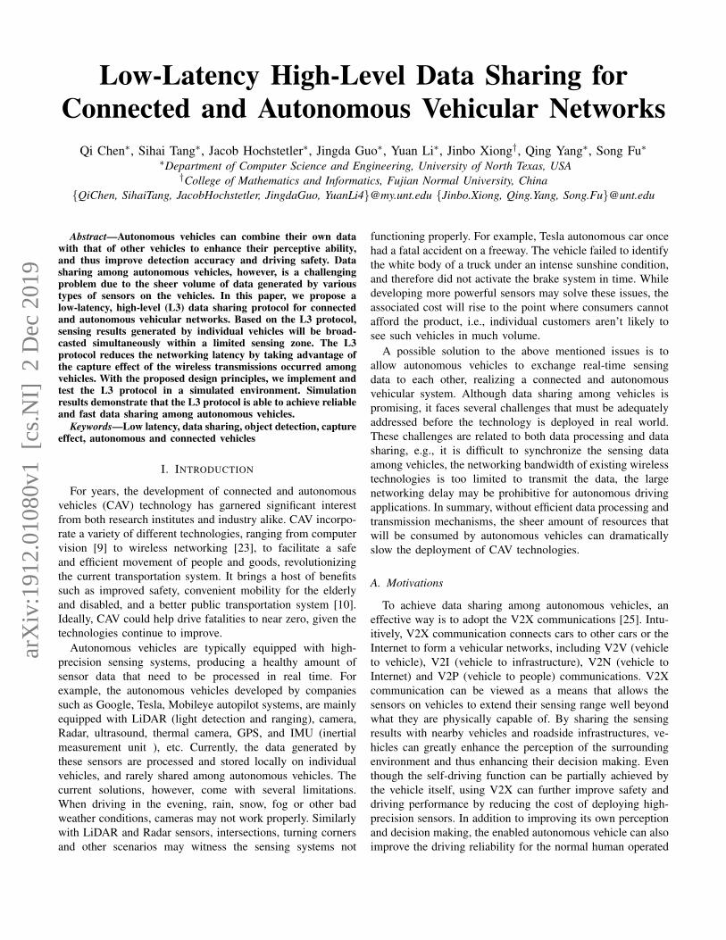
We use an example shown in Fig. 6a to illustrate howcapture effect would facilitate faster data sharing among threevehicles. Here, we assume vehicles 1, 2, and 3 are withinthe communication range of each other. The three vehiclesare assumed to reside in a zone containing 25 10m × 10mblocks. Based on its sensors, each vehicle could prepare asensing matrix. In the example, as vehicle 2 blocks the frontview of vehicle 1, there is an uncertain block in vehicle 1’ssensing matrix. According to the L3 protocol, vehicle 1 willinitiate the data sharing process via sending its sensing matrixin time slot 1. When vehicle 2 and 3 receive the messagefrom vehicle 1, they will aggregate the received data withtheir own data and update their sensing matrices. The updatedsensing matrices are then transmitted from vehicles 2 and 3simultaneously in time slot 2. Vehicle 1 will receive the updatesensing matrix from vehicle 2, due to capture effect. With thenew information contained in the receive message, vehicle 1will update its sensing matrix and send it in time slot 3. As nownew information is received, vehicle 2 does not send anythingin time slot 4. At time slot 5, because all vehicles have thesame sensing matrix, the data sharing process stops.
C. Data Aggregation Process
When sensing matrices are received from other vehicles, itis necessary to design a data aggregation process to combinethe received data with the current one. As we are focusingon enhancing the object detection capability of autonomousvehicles, the data aggregation must produce a sensing matrixthat contains all the objects detected by the sharing vehicles.
The data aggregation process on a vehicle starts fromidentifying whether the received data is generated from anothervehicle within the same zone. This can be done by comparingthe index of the zones where the vehicles reside. If the receivedsensing data, denoted as Rm×n, are for the same sensing zone,the aggregation will be carried out as follows. Here, we assumethere are m×n blocks within the current zone. Similarly, weuse Cm×n to denote the sensing matrix on the current vehiclewhich takes Rm×n to update its own sensing matrix.
To aggregate two matrices Rm×n and Cm×n, we willcompare all elements from these two matrices one by one.For a particular pair of elements, we use br1b
r0 and bc1b
c0 to
represent the sensing data in the received and current sensingmatrices, respectively. If br1 = 0, it implies the received datado not contain any useful information for the correspondingblock. Therefore, the value of bc1b
c0 will be kept unchanged.
On the other hand, if br1 = 1 and bc1 = 0, the the value ofbc1b
c0 will be replaced by br1b
r0. If br1 = bc1 = 1 but bc0 6= br0, it
means there is inconsistency on the object detection from the
(a)
(b)
(c)
Fig. 6: Illustration of how sensing matrices are exchangedamong three vehicles. (a) Three vehicles are located alonga line with vehicle 2 being closer to vehicle 1 than vehicle3. (b) The data communication process among three vehicles.Arrowed line indicates a packet is successfully delivered, dueto capture effect. Red cross means a packet is dropped. (c)The final sensing matrix on vehicle 1. It starts the data sharingprocess as it has a block with a value of (01). After 5 rounds ofdata exchange with others, the value of this block is updatedto (10).
two vehicles. In this case, as it is difficult to determine whichone offers the best detection result, we consider uncertainobservations were made. As a result, the value of bc1b
c0 becomes
01, which will again trigger the data sharing process. Webelieve this case is very rare and only occurs occasionally.The aggregation process will be applied to all pairs of elementsfrom two sensing matrices. The entire data aggregation processis summarized in Algorithm 1.
Fig 6b illustrates how messages are exchanged among thethree vehicles. We can see that the blocked area from vehicle
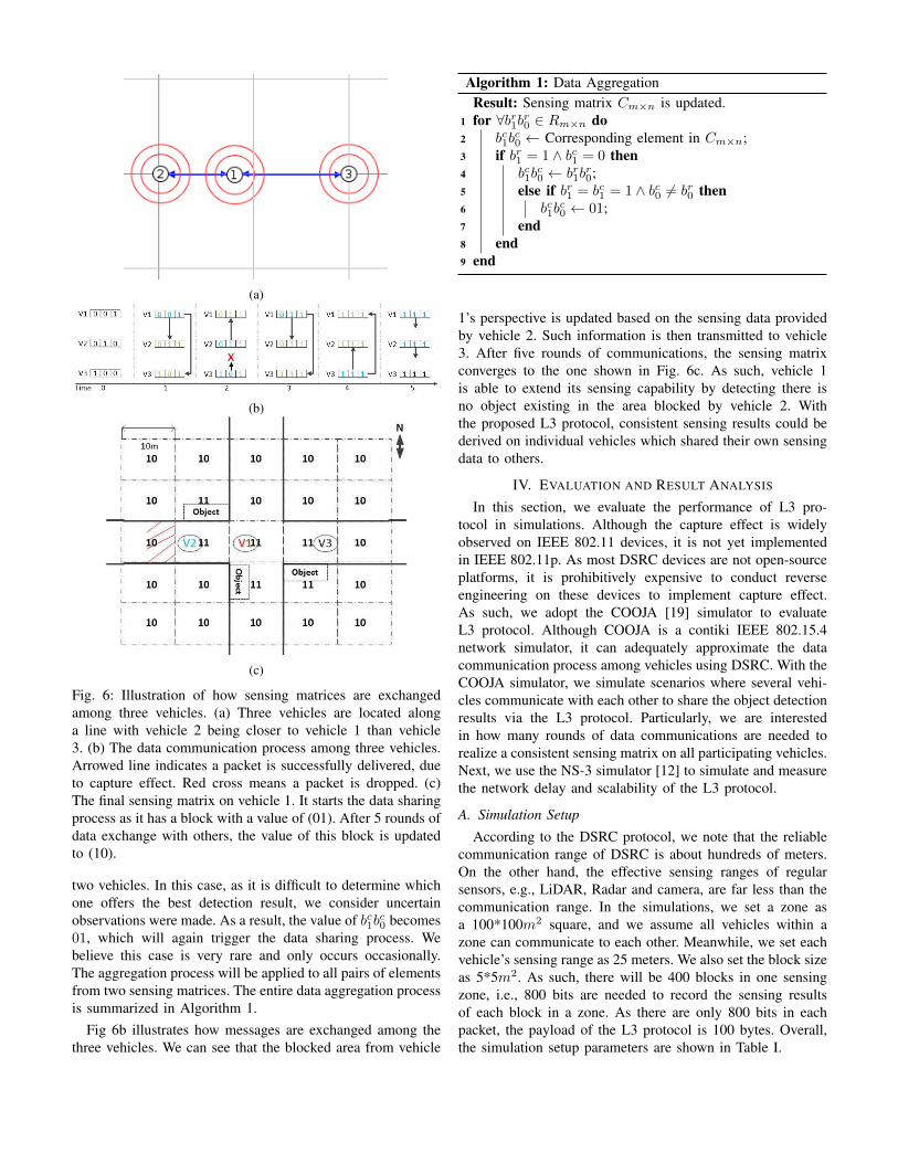
Algorithm 1: Data AggregationResult: Sensing matrix Cm×n is updated.
1 for ∀br1br0 ∈ Rm×n do2 bc1b
c0 ← Corresponding element in Cm×n;
3 if br1 = 1 ∧ bc1 = 0 then4 bc1b
c0 ← br1b
r0;
5 else if br1 = bc1 = 1 ∧ bc0 6= br0 then6 bc1b
c0 ← 01;
7 end8 end9 end
1’s perspective is updated based on the sensing data providedby vehicle 2. Such information is then transmitted to vehicle3. After five rounds of communications, the sensing matrixconverges to the one shown in Fig. 6c. As such, vehicle 1is able to extend its sensing capability by detecting there isno object existing in the area blocked by vehicle 2. Withthe proposed L3 protocol, consistent sensing results could bederived on individual vehicles which shared their own sensingdata to others.
IV. EVALUATION AND RESULT ANALYSIS
In this section, we evaluate the performance of L3 pro-tocol in simulations. Although the capture effect is widelyobserved on IEEE 802.11 devices, it is not yet implementedin IEEE 802.11p. As most DSRC devices are not open-sourceplatforms, it is prohibitively expensive to conduct reverseengineering on these devices to implement capture effect.As such, we adopt the COOJA [19] simulator to evaluateL3 protocol. Although COOJA is a contiki IEEE 802.15.4network simulator, it can adequately approximate the datacommunication process among vehicles using DSRC. With theCOOJA simulator, we simulate scenarios where several vehi-cles communicate with each other to share the object detectionresults via the L3 protocol. Particularly, we are interestedin how many rounds of data communications are needed torealize a consistent sensing matrix on all participating vehicles.Next, we use the NS-3 simulator [12] to simulate and measurethe network delay and scalability of the L3 protocol.
A. Simulation Setup
According to the DSRC protocol, we note that the reliablecommunication range of DSRC is about hundreds of meters.On the other hand, the effective sensing ranges of regularsensors, e.g., LiDAR, Radar and camera, are far less than thecommunication range. In the simulations, we set a zone asa 100*100m2 square, and we assume all vehicles within azone can communicate to each other. Meanwhile, we set eachvehicle’s sensing range as 25 meters. We also set the block sizeas 5*5m2. As such, there will be 400 blocks in one sensingzone, i.e., 800 bits are needed to record the sensing resultsof each block in a zone. As there are only 800 bits in eachpacket, the payload of the L3 protocol is 100 bytes. Overall,the simulation setup parameters are shown in Table I.

TABLE I: Simulation setup parameters
Communication Range 100mSensing Range 25mPayload Size 100 bytesZone Size 100m× 100mBlock Size 5m× 5m
B. Convergence Time
L3 is designed to realize low-latency data sharing amongautonomous vehicles, therefore, it is important to evaluatehow long it takes to ensure all participating vehicles have theconsistent sensing matrix. The latency can be measured in twodimensions: (1) number of time slots taken and (2) the actualtime taken to reach a consistent sensing matrix on vehicles. Inthis section, we evaluate the how many time slots are neededto complete the data sharing process among vehicles.
In the simulation, we place 9 vehicles in a grid using theCOOJA simulator, as shown in Fig. 7a. The horizontal/verticaldistance between two adjacent vehicles is set to be 10m. Wefirst let vehicle 1 to initiate the data sharing process, whichrepresents the cases where vehicles located around the cornersof the grid to start communications. We then record howmany time slots a vehicle is in its transmission or receptionmodes, until all 9 vehicles have the same sensing matrix. Asshown in Fig. 7c, after a total of 15 rounds of data exchange,all vehicles reach the same sensing matrix, i.e., the sensingresults converge. For vehicle 1, it transmits its original (orupdated) sensing matrix for 7 time slots and receive data fromothers in 8 time slots. For vehicles 2 and 3, as they are in theperfect location of receiving sensing data, their sensing matrixconverges after the 12th round of data exchange. After that,they simply broadcast the converged sensing matrix one moretime. Due to constructive interference, their transmissions willnot collide even though two packets are transmitted duringthe same time slot. After the 13th time slot, vehicles 2 and 3finish the data sharing process and they do not send or receiveany new data. At the 14th time slot, vehicle 6 receives themessage from vehicle 3, due to capture effect as vehicle 6 iscloser to vehicle 3. As such, vehicle 3 received the convergedsensing matrix and concludes its data sharing process as well.The remaining vehicles will finish the sensing matrix updatingprocess in a similar manner. After 15 rounds of data exchange,all vehicles obtain the same sensing matrix for the targetedsensing zone.
Next, we make vehicle 5 serve as the initiator, whichrepresents the cases where vehicles in the middle of a sensingzone starts the data sharing process. As shown in Fig. 7b,vehicle 5 starts sending and collecting sensing data fromothers. Different from our expectation, in this case, it takesa total of 17 time slots to finish the data sharing process.This is mainly because it takes a longer time for data fromvehicles at one side to propagate to those at the other side. Thedistribution of transmission and reception activities of eachvehicle is plotted in Fig. 7d. As we can see, vehicle 3, 5, 6and 9 receive the converged sensing matrix after the 14th time
(a) (b)
1 2 3 4 5 6 7 8 9Vehicle ID
0
2
4
6
8
10
12
14
16
Tim
es
TxRx
(c)
1 2 3 4 5 6 7 8 9
Vehicle ID
0
2
4
6
8
10
12
14
16
18
Tim
es
TxRx
(d)
Fig. 7: Convergence time of 9 vehicles exchanging sensingmatrices between each other. (a) Vehicle 1 located at top-leftcorner initiates the data sharing process. (b) Vehicle 5 located inthe middle initiates the data sharing process. (c) The distributionof time slots in which vehicles are in transmission and receptionmodes, respectively. (d) The distribution of time slots in whichvehicles are in transmission and reception modes when vehicle5 is the initiator.
slot. They broadcast the sensing result one more time and thenkeep silent. Vehicles 1, 2, and 4, on the other hand, receivevehicle 5’s message at the 15th time slot, due to capture effect.As the message contains the final sensing matrix, they all haltthe sharing process after one more round of broadcasting. Thelast two vehicles (7 and 8) complete their updating process atthe 17th time slot, and the entire sharing process is finished.
Besides the above simulations, we also conduct experimentswith different number of vehicles that are randomly deployedin a certain area. The convergence times of different scenarios,i.e., deploying 3 to 15 vehicles randomly in a zone, aresummarized and plotted in Fig. 8. We first deploy 3 vehiclesin a zone and it takes 4 time slots to finish the data sharingamong the three vehicles. The convergence time grows as moreand more vehicles join in the data sharing process. The totalnumber of rounds increases up to 26 time slots when there are15 vehicles in the network.
C. Network Latency
Networking latency of the L3 protocol highly depends onthe setting of the time slot, i.e., longer the time slot, largerthe networking delay. To achieve a low-latency protocol, it iscritical to set the time slot as small as possible. To identifythe best setting of time slot, we need to understand howlong it takes to transmit, receive and process 100 bytes of

0 2 4 6 8 10 12 14 16 18 20 22 24 26 28
Times
0
0.1
0.2
0.3
0.4
0.5
0.6
0.7
0.8
0.9
1C
DF
(%
)Vehicles #:
3 4 5 7
9 11
13
15
Fig. 8: Completion times of data sharing with different numberof vehicles in the network.
data in a vehicular network. We adopt NS-3 simulator [12]to find the minimal required time to finish each round ofdata transmission between vehicles. To obtain an accuratemeasurement of the time, we simulate two vehicles (100maway from each other) communicating to each other in NS-3.In the simulation, one vehicle transmits a 100-byte messageto another vehicle, using the IEEE 802.11p protocol withCSMA/CA disabled. In this case, the time needed to transmitand receive a 100-byte message is similar to that obtainedfrom capture effect. Here, the time is what is needed for thereceiving vehicle to successfully receive the message from thetransmitting vehicle. In our simulation, it requires less than2ms to share a 100-byte message between two vehicles. Whenthe vehicles are closer to each other, the time will be a bitsmaller, due to a shorter propagation delay that is neglected inthis paper. As such, we configure the time slot to be 2ms in oursimulations. Fig. 9 shows the actual delay of the data sharingprocess, with different numbers of vehicles in the simulations.In the figure, there is a notable improvement on latency inL3 over the IEEE 802.11p. This is because the IEEE 802.11pprotocol requires vehicles to compete to access the wirelesschannels, which may cause a significant networking delay.
D. Scalability
With more vehicles, the data sharing among vehicles maytake a longer time to complete. In this section, we conductexperiments to evaluate L3’s scalability, i.e., understandinghow L3 performs when the number of vehicles increases inthe network. As seen in Fig. 10, we witness that the networkdelay of L3 is increases slightly as the number of participatingvehicles increases. On the other hand, the latency of IEEE802.11p tends to perform poorly when there are large number
3 4 5 6 7 8 9 10 11 12 13 14 15 16
# of Vehicles
10
20
30
40
50
60
70
Del
ay(m
s)
L3IEEE 802.11p
Fig. 9: Network delay with different numbers of vehicles.
25 50 75 100 125 150
# of Vehicles
0
200
400
600
800
1000
1200
Del
ay(m
s)
IEEE 802.11pInitiator in corner area (L3)Initiator in middle area (L3)
Fig. 10: Network delay in a large scale vehicular network.
of vehicles transmitting packets simultaneously. As vehiclesbenefiting from the shared data and not suffering from theconsequences of large latency, L3 is proved to be effectivefor up to as many as 225 vehicles in a sensing zone. Withthe current traffic infrastructure, there is usually less than 225vehicle within any reasonable intersection in any city. In someextremely crowded areas, the number of vehicles could belarger than 255, which may cause a longer network latency.To address this issue, we could reduce the size of each sensingzone to include no more than 225 vehicles. The parametersetting of L3 protocol is not static and needs to be changedbased on real-world applications.
V. RELATED WORK
Object detection failures and visual obstructions are bothcore difficulties that all autonomous vehicle must face. Tech-niques such as cooperative perception (COOPER) [5] andothers address this problem from a fundamental level throughfusion. While detection results are improved, the wirelessbandwidth available for V2X communications is too limitedto support huge amount of data transmission among vehicles.

Currently-known fusion methods for connected and au-tonomous vehicles are categorized into three types: low-level, middle-level and high-level fusions. Low-level fusionis also called raw data fusion in which the original sens-ing data produced by vehicles are transmitted and sharedamong vehicles [17], [5]. While middle-level fusion methodsmake use of the extracted features from raw data to conductfusion [14], high-level fusion mainly combines the sensingresults processed by individual vehicles [1]. Other approacheslike [22] and [20], marry the different sensors from the samevehicle to improve their object detection accuracy.
With the current works detailing the ground work, we knowthat communication in between vehicles plays an importantlimiting role based on the type of fusion methods beingutilized. Taking COOPER [5] for example, while this methodimproves detection by merging point cloud data, it is limitedby the narrow bandwidth available in vehicular networks. Notonly does using higher quality sensors increase the amountof data that gets generated, using higher quality data alsoposses the risk that the data being generated will be toobig to be transferred efficiently. Works exploring the sharingdata between autonomous vehicles such as [13], discusses theuses of implementing V2X and identifies the requirementsfor doing so. The fundamental issue here is that existingvehicular network standards are design to exchange shortmessages among vehicles, rather than sensing data whichcould potentially be very large.
VI. CONCLUSIONS
We propose the L3 protocol to support low-latency datasharing among autonomous vehicles towards the goal of abetter detection of objects around autonomous driving cars.Due to the capture effect, all vehicles transmit their sensingmatrices simultaneously and thus a low-latency data sharingamong vehicles is achieved. Although the design of L3 proto-col is verified and evaluated in simulations, it is worth notingthat the implementation of L3 on real-world hardware is stilla challenging problem. In the future, we will explore thepossibility of integrating L3 into existing DSRC devices anddemonstrate how L3 works in real-world experiments.
ACKNOWLEDGMENT
The work is partially supported by National Science Foun-dation (NSF) grants NSF CNS-1761641 and CNS 1852134.
REFERENCES
[1] M. Aeberhard and N. Kaempchen. High-level sensor data fusionarchitecture for vehicle surround environment perception. In Proc. 8thInt. Workshop Intell. Transp, 2011.
[2] J. Arnbak and W. Van Blitterswijk. Capacity of slotted aloha in rayleigh-fading channels. IEEE Journal on Selected Areas in Communications,5(2):261–269, 1987.
[3] G. Bianchi, L. Fratta, and M. Oliveri. Performance evaluation andenhancement of the csma/ca mac protocol for 802.11 wireless lans. InProceedings of PIMRC’96-7th International Symposium on Personal,Indoor, and Mobile Communications, volume 2, pages 392–396. IEEE,1996.
[4] Q. Chen, B. Brendan, M. Wittie, P. Stacy, and Y. Qing. Moveset: Mod-ular vehicle sensor technology. IEEE Vehicular Networking Conference(VNC), December 2016.
[5] Q. Chen, S. Tang, Q. Yang, and F. Song. Cooper: Cooperative perceptionfor connected autonomous vehicles based on 3d point clouds. arXivpreprint arXiv:1905.05265, 2019.
[6] X. Chen, H. Ma, J. Wan, B. Li, and T. Xia. Multi-view 3d objectdetection network for autonomous driving. In The IEEE Conference onComputer Vision and Pattern Recognition (CVPR), July 2017.
[7] T. Cheng, G. Liu, Q. Yang, and J. Sun. Trust assessment in vehicular so-cial network based on three-valued subjective logic. IEEE Transactionson Multimedia, 21(3):652–663, 2019.
[8] P. Dutta, S. Dawson-Haggerty, Y. Chen, C.-J. M. Liang, and A. Terzis.Design and evaluation of a versatile and efficient receiver-initiated linklayer for low-power wireless. In Proceedings of the 8th ACM Conferenceon Embedded Networked Sensor Systems, pages 1–14. ACM, 2010.
[9] A. Geiger, P. Lenz, and R. Urtasun. Are we ready for autonomousdriving? the kitti vision benchmark suite. In 2012 IEEE Conferenceon Computer Vision and Pattern Recognition, pages 3354–3361. IEEE,2012.
[10] J. Guo, X. Cheng, and Q. Yang. Detection of occluded road signs onautonomous driving vehicles. In 2019 IEEE International Conferenceon Multimedia and Expo (ICME). IEEE, 2019.
[11] M. Haghighat, M. Abdel-Mottaleb, and W. Alhalabi. Discriminant corre-lation analysis: Real-time feature level fusion for multimodal biometricrecognition. IEEE Transactions on Information Forensics and Security,11(9):1984–1996, 2016.
[12] T. R. Henderson, M. Lacage, G. F. Riley, C. Dowell, and J. Kopena.Network simulations with the ns-3 simulator. SIGCOMM demonstration,14(14):527, 2008.
[13] L. Hobert, A. Festag, I. Llatser, L. Altomare, F. Visintainer, and A. Ko-vacs. Enhancements of v2x communication in support of cooperativeautonomous driving. IEEE communications magazine, 53(12):64–70,2015.
[14] N. Kaempchen, M. Buehler, and K. Dietmayer. Feature-level fusion forfree-form object tracking using laserscanner and video. In Intelligentvehicles symposium, 2005. Proceedings. IEEE, pages 453–458. IEEE,2005.
[15] J. B. Kenney. Dedicated short-range communications (dsrc) standardsin the united states. Proceedings of the IEEE, 99(7):1162–1182, 2011.
[16] L. A. Klein and L. A. Klein. Sensor and data fusion: a tool forinformation assessment and decision making, volume 324. SPIE pressBellingham, 2004.
[17] R. Labayrade, C. Royere, D. Gruyer, and D. Aubert. Cooperative fusionfor multi-obstacles detection with use of stereovision and laser scanner.Autonomous Robots, 19(2):117–140, 2005.
[18] O. Landsiedel, F. Ferrari, and M. Zimmerling. Chaos: Versatile andefficient all-to-all data sharing and in-network processing at scale. InACM Embedded Networked Sensor Systems, November 2013.
[19] F. Osterlind, A. Dunkels, J. Eriksson, N. Finne, and T. Voigt. Cross-level sensor network simulation with cooja. In First IEEE InternationalWorkshop on Practical Issues in Building Sensor Network Applications(SenseApp 2006), 2006.
[20] C. R. Qi, W. Liu, C. Wu, H. Su, and L. J. Guibas. Frustum pointnetsfor 3d object detection from rgb-d data. In Proceedings of the IEEEConference on Computer Vision and Pattern Recognition, pages 918–927, 2018.
[21] O. Savas and J. Deng. Big data analytics in cybersecurity. AuerbachPublications, 2017.
[22] D. Xu, D. Anguelov, and A. Jain. Pointfusion: Deep sensor fusion for3d bounding box estimation. In Proceedings of the IEEE Conferenceon Computer Vision and Pattern Recognition, pages 244–253, 2018.
[23] Q. Yang, A. Lim, S. Li, J. Fang, and P. Agrawal. Acar: Adaptive con-nectivity aware routing for vehicular ad hoc networks in city scenarios.Mob. Netw. Appl., 15(1):36–60, Feb. 2010.
[24] Q. Yang and H. Wang. Towards trustworthy vehicular social network.IEEE Communication Magazine, 53(8):42–47, 2015.
[25] Q. Yang, B. Zhu, and S. Wu. An architecture of cloud-assistedinformation dissemination in vehicular networks. IEEE Access, 4:2764–2770, 2016.
[26] J. Yick, B. Mukherjee, and D. Ghosal. Wireless sensor network survey.Computer networks, 52(12):2292–2330, August 2008.
[27] Y. Zhou and O. Tuzel. Voxelnet: End-to-end learning for point cloudbased 3d object detection. In The IEEE Conference on Computer Visionand Pattern Recognition (CVPR), June 2018.