Low Emittance Tuning in CESR TA
27
Low Emittance Tuning in CESR TA D. Rubin Cornell University April 18, 2009
description
Low Emittance Tuning in CESR TA. D. Rubin Cornell University April 18, 2009. Objectives. Attain sufficiently low vertical emittance to enable exploration of - dependence of electron cloud on emittance - emittance diluting effect of e-cloud - PowerPoint PPT Presentation
Transcript of Low Emittance Tuning in CESR TA
Low Emittance Tuning in CESR TA
D. Rubin
Cornell University
April 18, 2009

April 18, 2009 TILC09 AAP review - CesrTA 2
Objectives
Attain sufficiently low vertical emittance to enable exploration of - dependence of electron cloud on emittance - emittance diluting effect of e-cloud
• Design/deploy low emittance optics (1.5 < Ebeam< 5.0 GeV)– Exploit damping wigglers to reduce damping time and emittance
• Establish efficient injection of electrons and positrons• Develop beam based techniques for characterizing beam position monitors
– BPM offsets, Gain mapping, ORM and transverse coupling measurements > BPM tilt• And for measuring and minimizing sources of vertical emittance including
– Misalignments – Orbit errors– Focusing errors– Transverse coupling– Vertical dispersion
• Develop single bunch/single pass measurement of vertical beam size• Characterize current dependence of lifetime in terms of beam size• Measure dependencies of beam size/lifetime on
– Beam energy– Bunch current– Species– Etc.
April 18, 2009 TILC09 AAP review - CesrTA 3
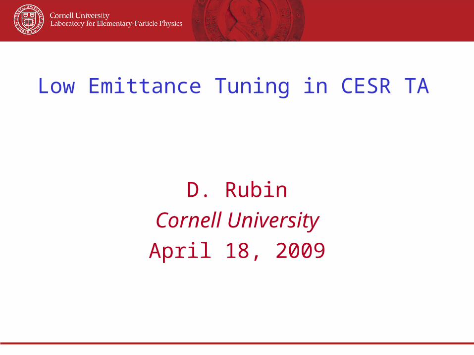
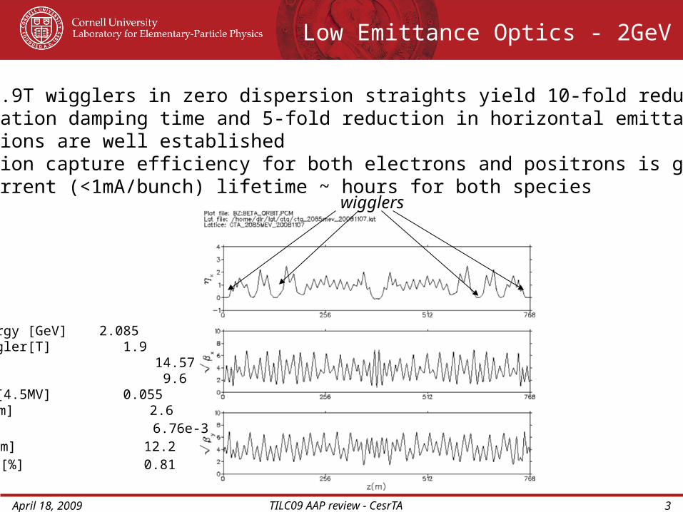
Low Emittance Optics - 2GeV
Energy [GeV] 2.085Wiggler[T] 1.9Qx 14.57Qy 9.6Qz [4.5MV] 0.055x[nm] 2.6p 6.76e-3l[mm] 12.2E/E[%] 0.81
wigglers
Twelve 1.9T wigglers in zero dispersion straights yield 10-fold reduction in radiation damping time and 5-fold reduction in horizontal emittance- Conditions are well established- Injection capture efficiency for both electrons and positrons is good- Low current (<1mA/bunch) lifetime ~ hours for both species

April 18, 2009 TILC09 AAP review - CesrTA 4
Low Emittance Optics - 5GeV
(Wigglers off)Energy [GeV] 5.0 Wiggler[T] 1.9 0Qx 14.57Qy 9.6Qz [8 MV] 0.043x[nm] 35 60p 6.23e-3l[mm] 15.6 9.4 rad [ms] 20 30E/E [%] 0.93 0.58
wigglers
Six 1.9T wigglers in L0 - zero dispersion(Arc vacuum chambers cannot tolerate wiggler radiation)

April 18, 2009 TILC09 AAP review - CesrTA 5
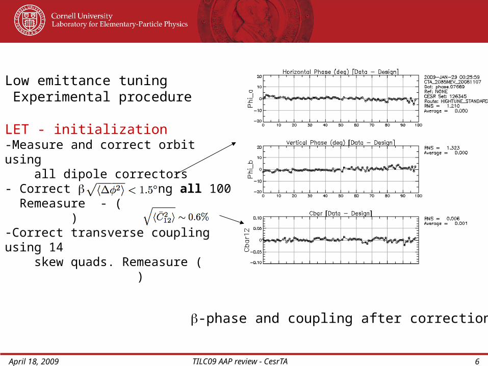
Low emittance tuning Experimental procedure
LET - initialization-Measure and correct orbit using all dipole correctors-Measure -phase and transverse coupling (Phase measurement insensitive to BPM offset, gain, and calibration errors)
Measurement at January 09 startup after 2 month CHESS (5.3GeV) run
Measure -phase and coupling
April 18, 2009 TILC09 AAP review - CesrTA 6
Low emittance tuning Experimental procedure
LET - initialization-Measure and correct orbit using all dipole correctors- Correct -phase using all 100 Remeasure - ( )-Correct transverse coupling using 14 skew quads. Remeasure ( )
-phase and coupling after correction
April 18, 2009 TILC09 AAP review - CesrTA 7
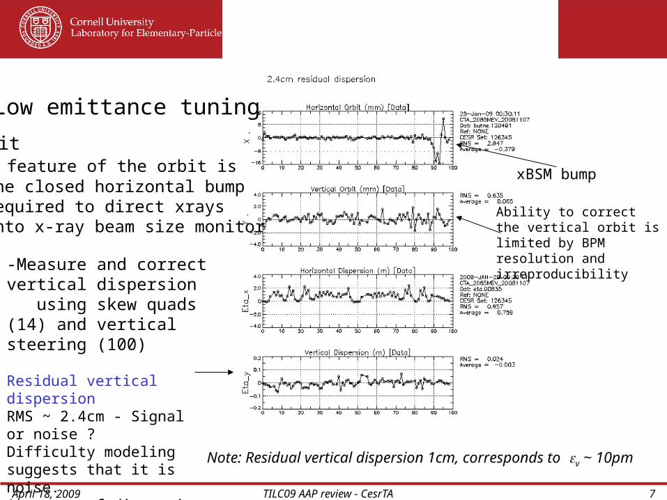
Low emittance tuning
xBSM bump
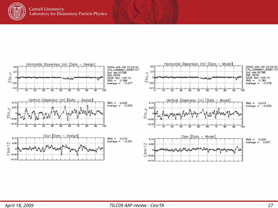
-Measure and correct vertical dispersion using skew quads (14) and vertical steering (100)
Residual vertical dispersionRMS ~ 2.4cm - Signal or noise ?Difficulty modeling suggests that it is noise. Accuracy of dispersion measurement is limited by BPM systematics
Note: Residual vertical dispersion 1cm, corresponds to v ~ 10pm
Orbit A feature of the orbit is the closed horizontal bump required to direct xrays onto x-ray beam size monitor
Ability to correct the vertical orbit is limited by BPM resolution and irreproducibility
April 18, 2009 TILC09 AAP review - CesrTA 8
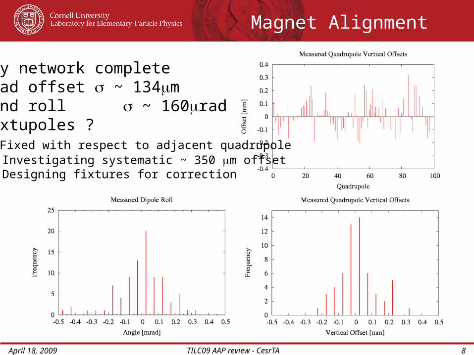
Magnet Alignment
Survey network complete - Quad offset ~ 134m - Bend roll ~ 160rad - Sextupoles ? Fixed with respect to adjacent quadrupole Investigating systematic ~ 350 m offset Designing fixtures for correction
April 18, 2009 TILC09 AAP review - CesrTA 9
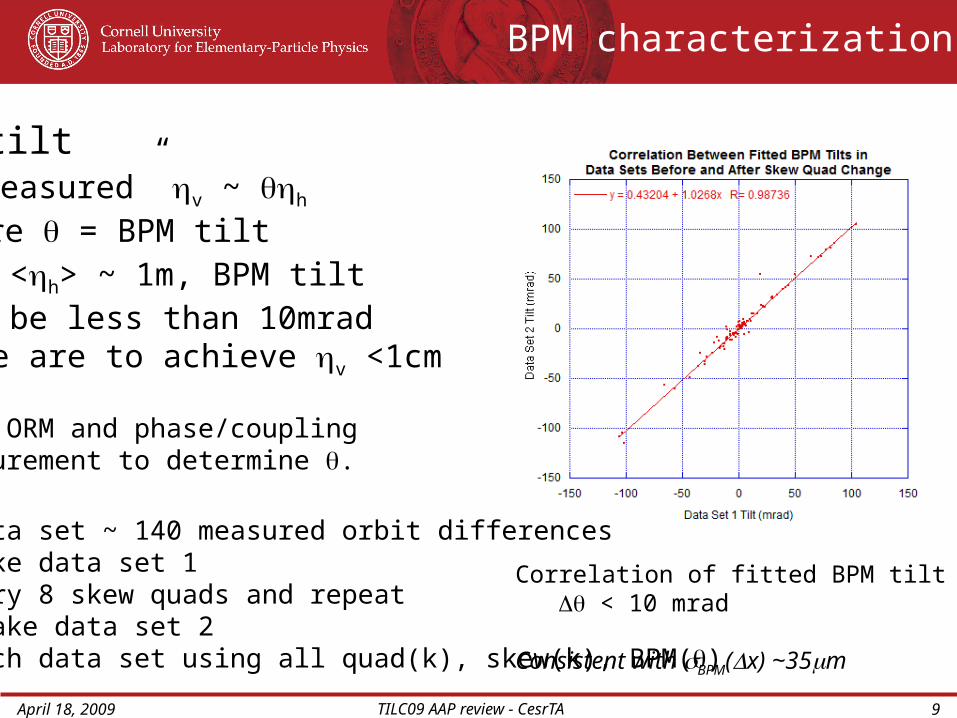
BPM characterization
BPM tilt - “measured” v ~ h
where = BPM tiltSince <h> ~ 1m, BPM tilt must be less than 10mrad if we are to achieve v <1cm
We use ORM and phase/coupling measurement to determine .
ORM data set ~ 140 measured orbit differences - Take data set 1 - Vary 8 skew quads and repeat - Take data set 2 Fit each data set using all quad(k), skew(k), BPM()
Correlation of fitted BPM tilt () < 10 mrad
Consistent with BPM(x) ~35m

April 18, 2009 TILC09 AAP review - CesrTA 10
BPM upgrade
Existing BPM electronics measure stretched signal and share common signal processing via mechanical relays
New system - Bunch by bunch/turn by turn digitization - 4ns bunch spacing - (x) < 10mStatus Infrastructure (cables,crates, etc.) fully deployed in tunnel Conversion from old system to new is underway - taking care to maintain full functionality during the transition
With the new system we will measure:
- Quad - BPM offset < 50 m via beam based alignment (Vary quad K to find center) - ~ x/(E/E) ~ 10m /10-3 ~ 1cm - Clean measurement of C11, C12, C22
discriminates BPM tilt and transverse coupling (C12 independent of tilt)
April 18, 2009 TILC09 AAP review - CesrTA 11
Lifetime
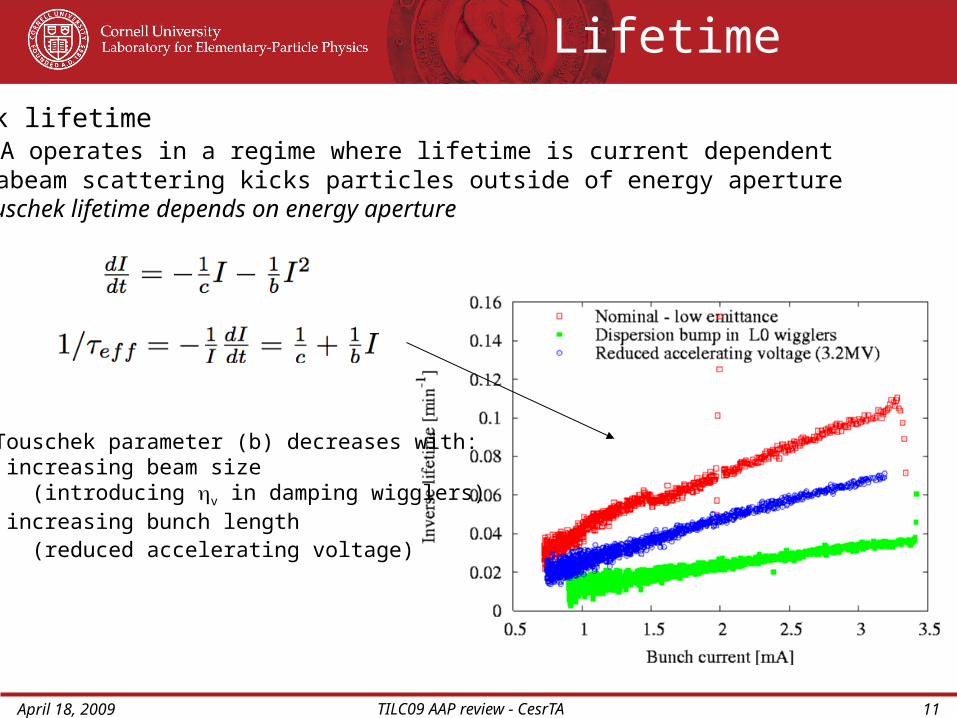
Touschek lifetime CesrTA operates in a regime where lifetime is current dependent Intrabeam scattering kicks particles outside of energy aperture Touschek lifetime depends on energy aperture
The Touschek parameter (b) decreases with: - increasing beam size (introducing v in damping wigglers) - increasing bunch length (reduced accelerating voltage)
April 18, 2009 TILC09 AAP review - CesrTA 12
Lifetime
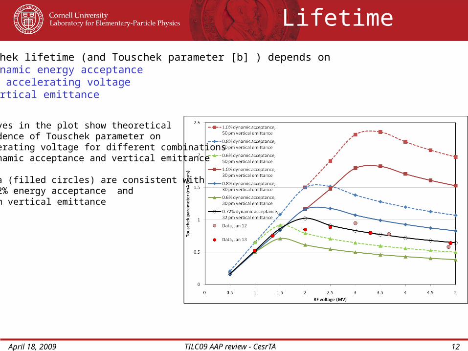
Touschek lifetime (and Touschek parameter [b] ) depends on - dynamic energy acceptance - RF accelerating voltage - vertical emittance
The curves in the plot show theoretical dependence of Touschek parameter on accelerating voltage for different combinations of dynamic acceptance and vertical emittance
The data (filled circles) are consistent with 0.72% energy acceptance and 32pm vertical emittance

April 18, 2009 TILC09 AAP review - CesrTA 13
Tracking model includes:-magnet misalignments -wiggler and quadrupole nonlinearity-Orbit errors
Energy acceptance ~ 1.8%
Dynamic energy aperture
Nonlinearity of dipole correctors and sextupoles has not yet been included.
Interpretation of lifetime measurements requires knowledge of dynamic energy acceptance Tracking study indicates energy acceptance ~1.8% (lifetime measurements suggest significantly smaller energy acceptance)
April 18, 2009 TILC09 AAP review - CesrTA 14
Energy Acceptance
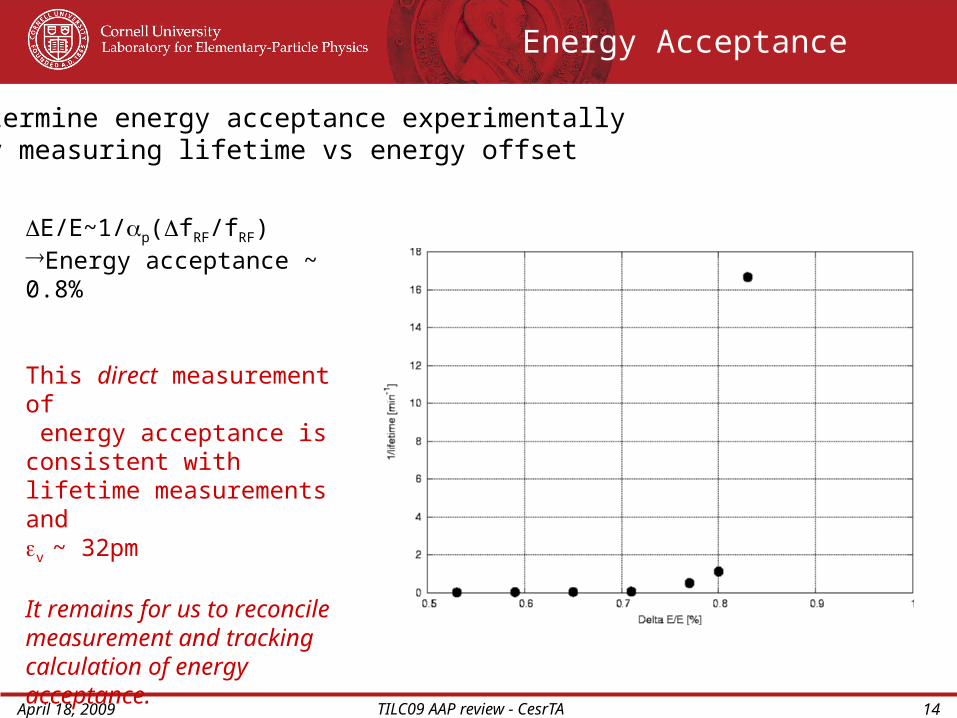
E/E~1/p(fRF/fRF)Energy acceptance ~ 0.8%
This direct measurement of energy acceptance is consistent with lifetime measurements andv ~ 32pm
It remains for us to reconcile measurement and tracking calculation of energy acceptance.
Determine energy acceptance experimentally by measuring lifetime vs energy offset

April 18, 2009 TILC09 AAP review - CesrTA 15
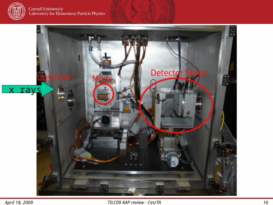
Detector Box
Fast gatevalve
Rough pumps
diamond windowturbo gate valve
low quality vacuum (10-3)
high quality vacuum (10-7)
x rays
Xray Beam Size Monitor
At 2GeV beam energy, xrays from abending magnet are at such low energythat a Be window is not sufficiently transparent
April 18, 2009 TILC09 AAP review - CesrTA 16
x rays

April 18, 2009 TILC09 AAP review - CesrTA 17
xBSM Snapshots
• Scan of coupling knob
• Coded aperture measurements
• Smallest recorded size:
~15 m v~ 37pm (preliminary)
Simulations
First measurement
Fresnel Zone Plate
<45 mbeam size
CodedAperture
Monochromatic beam
White beam
April 18, 2009 TILC09 AAP review - CesrTA 18
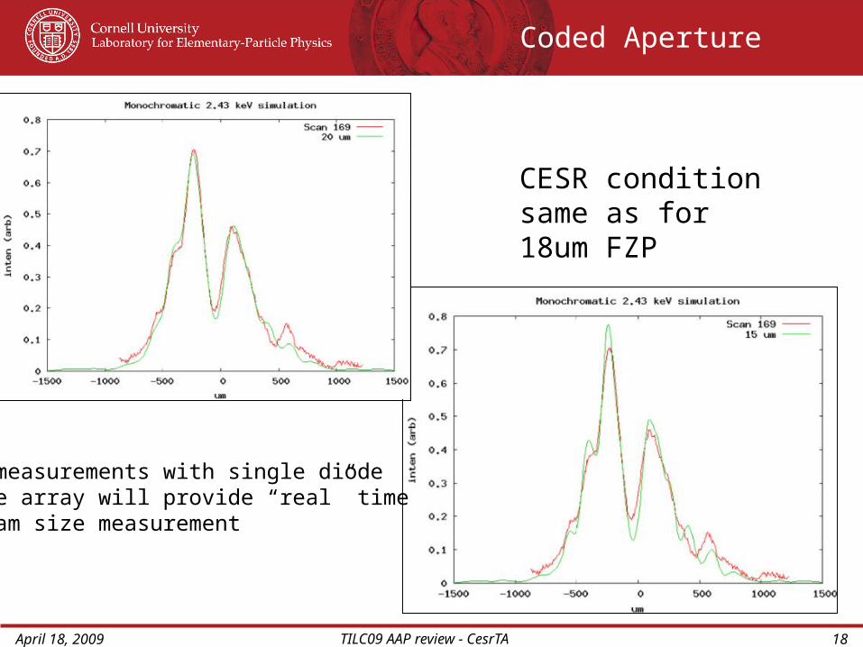
CESR condition same as for 18um FZP
Coded Aperture
All measurements with single diodeDiode array will provide “real” time beam size measurement
April 18, 2009 TILC09 AAP review - CesrTA 19
Xray Beam Size Measurement
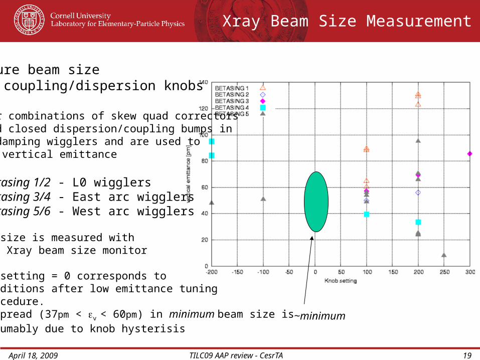
Measure beam size vs coupling/dispersion knobs
Linear combinations of skew quad correctors yield closed dispersion/coupling bumps in the damping wigglers and are used to tune vertical emittance
Betasing 1/2 - L0 wigglersBetasing 3/4 - East arc wigglersBetasing 5/6 - West arc wigglers
~minimum
Beam size is measured with the Xray beam size monitor
Knob setting = 0 corresponds to conditions after low emittance tuning procedure. The spread (37pm < v < 60pm) in minimum beam size is presumably due to knob hysterisis
April 18, 2009 TILC09 AAP review - CesrTA 20
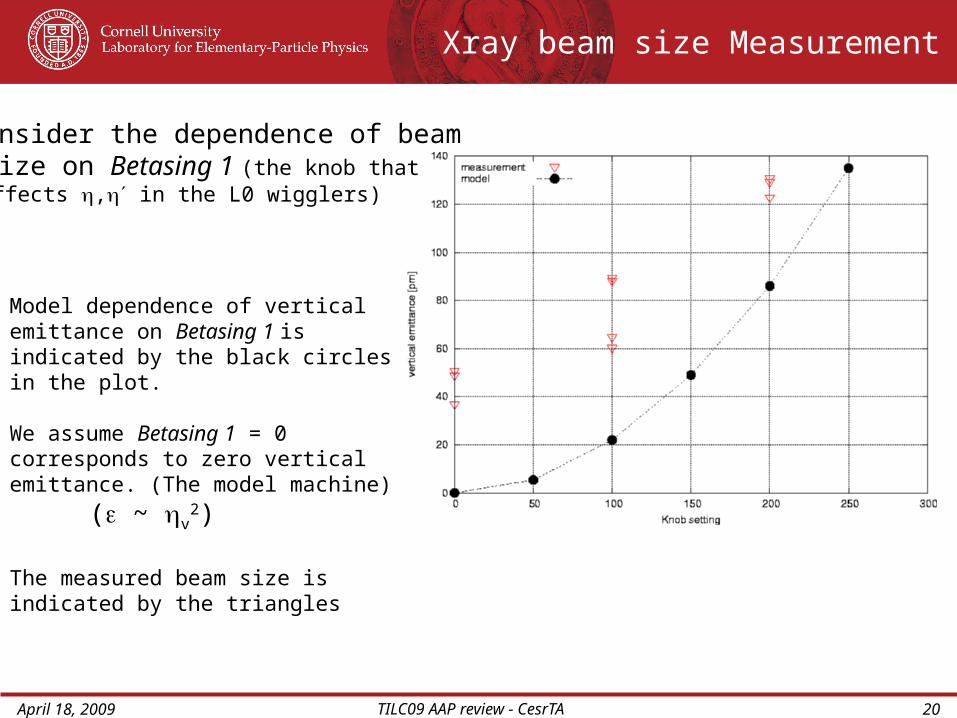
Consider the dependence of beam size on Betasing 1 (the knob that effects , in the L0 wigglers)
Model dependence of vertical emittance on Betasing 1 is indicated by the black circles in the plot.
We assume Betasing 1 = 0 corresponds to zero vertical emittance. (The model machine)
( ~ v2)
The measured beam size is indicated by the triangles
Xray beam size Measurement
April 18, 2009 TILC09 AAP review - CesrTA 21
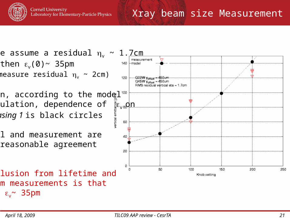
If we assume a residual v ~ 1.7cm then v(0)~ 35pm (we measure residual v ~ 2cm)
Again, according to the modelcalculation, dependence of v on Betasing 1 is black circles
Model and measurement are in reasonable agreement
Conclusion from lifetime and Xbsm measurements is that v~ 35pm
Xray beam size Measurement

April 18, 2009 TILC09 AAP review - CesrTA 22
The measurement1. Correct (flatten) orbit2. Correct coupling with skew quads3. Measure -phase and coupling4. Turn off all sextupoles and re-Measure -phase and coupling
The RMS phase difference is ~ 1°The RMS coupling difference is~ 4.2%
The measured coupling corresponds to systematic sextupole vertical offset of ~1mmDirect measurement suggest some such offset!
Low emittance tuning - limited by finite v
- Identification of the source requires better measurement
Consider the effect of sextupole misalignment
April 18, 2009 TILC09 AAP review - CesrTA 23
Low Emittance Tuning
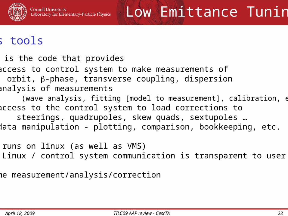
Analysis tools
CESRV is the code that provides - access to control system to make measurements of orbit, -phase, transverse coupling, dispersion - analysis of measurements (wave analysis, fitting [model to measurement], calibration, etc.) - access to the control system to load corrections to steerings, quadrupoles, skew quads, sextupoles … - data manipulation - plotting, comparison, bookkeeping, etc.
CESRV runs on linux (as well as VMS) - Linux / control system communication is transparent to user
> Real time measurement/analysis/correction
April 18, 2009 TILC09 AAP review - CesrTA 24
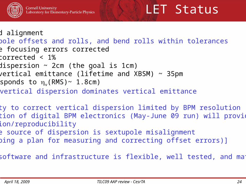
- Survey and alignment Quadrupole offsets and rolls, and bend rolls within tolerances- Quadrupole focusing errors corrected- Coupling corrected < 1%- Vertical dispersion ~ 2cm (the goal is 1cm)- Measured vertical emittance (lifetime and XBSM) ~ 35pm ( corresponds to v(RMS)~ 1.8cm) Residual vertical dispersion dominates vertical emittance - Our ability to correct vertical dispersion limited by BPM resolution-Implementation of digital BPM electronics (May-June 09 run) will provide required resolution/reproducibility [Candidate source of dispersion is sextupole misalignment (Developing a plan for measuring and correcting offset errors)]
- Analysis software and infrastructure is flexible, well tested, and mature
LET Status
April 18, 2009 TILC09 AAP review - CesrTA 25
J. Alexander, M. Billing, J. Calvey, S. Chapman, G. Codner, J. Crittenden, J. Dobbins, G. Dugan, M. Forster, R. Gallagher, S. Gray, S. Greenwald, D. Hartill, W. Hopkins, J. Kandaswamy, D. Kreinick, Y. Li, X. Liu, J. Livezey, V. Medjidzade, R. Meller, S. Peck, D. Peterson, M.Rendina, D. Rice, N. Rider, D. Sagan, J. Sexton, J. Shanks, J. Sikora, K. Smolenski, C. Strohman, A. Temnykh, M. Tigner, W. Whitney, H. Williams, S. Vishniakou, T. Wilksen (CLASSE, Cornell University)
K. Harkay (Argonne National Lab)
R. Holtzapple (California Polytechnic Institute)
E. Smith (CCMR, Cornell University)
C. Connolly, E. Fontes, A. Lyndaker, P. Revesz, J. Savino, R. Seeley (CHESS, Cornell University)
J.Jones, A. Wolski (Cockcroft Institute)
Y.He, M. Ross, C.Y.Tan, R. Zwaska (Fermi National Accelerator Laboratory)
J.Flanagan, P. jain, K. Kanazawa, K. Ohmi, Y. Suetsugu (KEK Accelerator Laboratory)J. Byrd, C.M.Celata, J. Corlett, S. De Santis, M. Furman, A. Jackson, R. Kraft, D. Munson, G. Penn, D. Plate, A. Rawlins, M. Venturini, M. Zisman (Lawrence Berkeley National Laboratory)
D. Kharakh, M. Pivi, L. Wang (SLAC National Accelerator Laboratory)
Acknowledgements
April 18, 2009 TILC09 AAP review - CesrTA 26
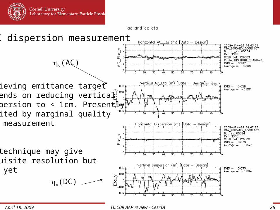
Achieving emittance targetdepends on reducing verticaldispersion to < 1cm. Presentlylimited by marginal quality of measurement
AC technique may giveRequisite resolution but not yet
v(AC)
v(DC)
AC dispersion measurement
April 18, 2009 TILC09 AAP review - CesrTA 27