Longtime Performance of Trussed Rafters with … States Department of Agriculture Forest Service...
21
United States Department of Agriculture Forest Service Forest Products Laboratory Longtime Performance of Trussed Rafters with Different Connection Systems Research Paper FPL 444 Thomas Lee Wilkinson
Transcript of Longtime Performance of Trussed Rafters with … States Department of Agriculture Forest Service...

United StatesDepartment ofAgriculture
Forest Service
ForestProductsLaboratory
LongtimePerformance ofTrussed Rafters withDifferent ConnectionSystems
ResearchPaperFPL 444
Thomas Lee Wilkinson

Abstract
Trussed rafters with seven different connecting systemswere observed under load for periods of 5, 10, and 15years. After each 5-year period, trusses were unloadedand evaluated for strength and stiffness under laboratoryconditions.
At the end of 15 years, total deflection of the trussesunder constant load increased about two to three timesthe initial deflection. Total deflection was still at anacceptable level. Creep had halted during the 15 years ofobservation. Trusses evaluated in the laboratory had noappreciable loss of strength or stiffness except for a 30percent reduction in stiffness with the nailed plywoodgusset trussed rafters.
Keywords: Connectors, fasteners, glue, gussets, rafters,trussed rafters.
Wilkinson, Thomas Lee. Longtime performance oftrussed rafters with different connection systems.Res. Pap. FPL 444. Madison, Wis.: U.S. Department ofAgriculture, Forest Service Forest Products Laboratory;1984. 19 p.
A limited number of free copies of this publication areavailable to the public from the Forest ProductsLaboratory, P.O. Box 5130, Madison, WI 53705.Laboratory publications are sent to over 1,000 librariesin the United States and elsewhere.
The Laboratory is maintained in cooperation with theUniversity of Wisconsin.
This paper supersedes Forest Service Research PapersFPL 93 dated 1968; FPL 204 dated 1973; and FPL 204revised 1978.

United StatesDepartment ofAgriculture
Forest Service
ForestProductsLaboratory1
ResearchPaperFPL 444
April 1984
LongtimePerformance ofTrussed Rafters withDifferent ConnectionSystemsThomas Lee Wilkinson, EngineerForest Products Laboratory, Madison, Wis.
Introduction
Wood trussed rafters have become widely used in thehousing and small building industry because of theiradvantages over conventional rafters. These advantagesinclude:1. Fast close-in.—Trussed rafters can be erected and the
sheathing applied in a minimum of time.2. Complete freedom of floor plan design.—Outside walls
completely support the roof load; therefore, the partitionwalls can be put anywhere.
3. Less skilled labor for erection.—There is no framing,layout, or rafter cutting done on the site.
4. Savings in lumber.—Interior partitions can be madelighter, since they are nonload-bearing. Nominal size2 by 4 members are used in the trussed rafter,compared to nominal size 2 by 6 and 2 by 8 rafters andceiling joists used in conventional systems.
After a trussed rafter is installed in a building, it issubjected to many conditions which may affect itsperformance. These conditions include changes in relativehumidity and temperature which cause the truss membersand connectors to expand and contract, and thus mayloosen the connector. Conditions of loading, such aschanges in the amount of live load on the roof, may causethe joint to “work” and thus result in a change inperformance. A constant load, such as roofing materials,may cause continued deflection with time. Theseconditions in different combinations and degrees mayaffect the service performance of wood trussed rafters.
Service characteristics of trussed rafters or theirconnection systems have received little study. Trussedrafters assembled with nailed plywood gusset plates andwithout glue have performed satisfactorily, as indicated bytheir long service records. The metal plate connector hasa 30-year service record with over 700 million in use.Their in-service performance has also been satisfactory.
In 1967, the Forest Products Laboratory initiated a studyon the longtime performance of trussed rafters withdifferent connection systems. The trussed rafters wereloaded and exposed to sheltered outdoor conditions for5-, 10-, and 15-year periods. After each 5-year period, onetrussed rafter of each connection system was evaluated inthe laboratory. Strength and stiffness was compared to acontrol trussed rafter tested at the program’s beginning.
Results after 5 and 10 years have been reportedpreviously (Wilkinson, 1978). This paper contains theresults from all three periods.
1 Maintained at Madison, Wis. in cooperation with the University ofWisconsin.

Other Trussed Rafter Studies
When this study began, several studies had beenconducted on full-size trussed rafters to determine theirinitial strength and stiffness. These included tests byAngleton (1960) on roof trusses with nailed plywoodgusset plates, by Luxford and Heyer (1954) on glued andnailed roof trusses, by Pneuman (1960) on king-posttrussed rafters with plywood gussets on one side, as wellas many tests by Radcliffe and others (1955a, 1955b,1955c) on nail-glued trussed rafters. Also, themanufacturers of metal plates had tested trussed raftersfabricated with their metal gusset plates. All of the morepopular configurations and fastening systems wereincluded in these studies. All the trussed rafters hadadequate initial strength and stiffness.
Since this study began, tests of trussed rafters havecontinued. These tests have primarily been conducted toqualify new designs for code approval, or to check outnew methods of analysis. Because of the special purposeof these tests, most are not reported in the generalliterature.
Few studies have investigated the effect of in-serviceconditions on the performance of trussed rafters. Luxford(1958) investigated the effect of changes in relativehumidity on the strength and rigidity of trussed rafterswith nail-glued joints and nailed joints. Both types oftrussed rafters had ample strength and stiffness afterexposure for normal service conditions, but nail-gluedtrussed rafters were considerably stiffer and stronger thanthe nailed trussed rafters.
Radcliffe and Sliker (1964) studied the effect of moisturecontent on trussed rafters with four connection systems(three different metal plates and nail-glued plywoodgussets). One group was fabricated and tested at 10percent moisture content, and another group wasfabricated at 18 percent moisture content and tested at 6percent. Trussed rafters fabricated at the higher moisturecontent lost 2 to 28 percent in ultimate strength comparedto those fabricated at the lower moisture content. The lossin relative stiffness ranged from 5 to 29 percent.
Wilkinson (1966) investigated the effect of moisture cyclingon the strength and rigidity of nailed wood and plywood,metal-plate, and glued plywood trussed-rafter jointsfabricated at approximately 10, 17, and 25 percentmoisture content. Specimens were cycled between 20 and6 percent moisture content, after which they were testedand the results compared with those for matcheduncycled specimens. Both cycled and control tensionspecimens (made from nominal 2- by 4-in. material) wereloaded with 500 pounds during cycling. Elongation of thecycled tension specimens increased from 0 to 350 percentover the controls at a design load of 2,000 pounds. Thesevalues did not include residual elongations from thecycling. Losses in ultimate load ranged from 0 to 23percent.
When this study began, there had been no long-time loadtest of trussed rafters. During the time since, Suddarth etal. (1981) have conducted long-term load tests on parallel-chord floor trusses. Trusses were loaded at half theirdesign live load. The trusses deflected past L/360 in thesecond year of loading. Seasonal changes in the rate andamount of creep were observed.
Feldburg and Johansen (1976) presented the deflectiondata for trussed rafters subjected to alternating loadduring a year. During the year, the load was variedbetween 8 weeks of design dead load and 1 week ofdesign dead load plus design snow load. Their studyincludes five different connection systems.
2

Specimens
W-type trussed rafters (fig. 1) with a slope of 4:12 and28-foot span (outside to outside of bearing walls) wereselected for this study. They were designed for a deadload of 10 pounds per square foot (Ib/ft2) on the bottomchord and a load of 26 lb/ft2 on the upper chord. The 26lb/ft2 load was composed of 10 Ib/ft2 dead load plus16 lb/ft2 live load. These were the loads used by metal-plate manufacturers for their trussed rafter designs. Thetrusses are designed for a 2-foot spacing.
The trussed rafter members consisted of nominal 2- by4-inch Douglas-fir (1-1/2 by 3-5/8 in.). The upper chordswere a 1,500f Industrial grade; the lower chords were1,200f Industrial grade; and the web members wereConstruction grade. The members were graded under1963 WWPA grading rules. All material had a moisturecontent of approximately 10 percent at the time offabrication.
Seven different connection systems were used:(a) Nailed plywood.(b) Nailed metal plate.(c) Toothed metal plate.(d) Barbed metal plate.(e) Casein glue with plywood gussets.(f) Phenol-resorcinol glue “A” with plywood gussets.(g) Phenol-resorcinol glue “B” with plywood gussets.
All plywood gussets were 1/2-inch, exterior gradeDouglas-fir. Sixpenny common nails were used for thenailed plywood trussed rafters and fourpenny commonwere used for the nail-glued trussed rafters. The metaltruss plates were selected as being representative ofthree general classifications: (1) Those which rely on nailsalone to carry loads transmitted through the joint, (2)those which rely on barbs and also some nails to carrythe load, and (3) those which depend solely upon teethpunched in the plate to carry the load. The plates selectedfor this study from each of the three groups are shown infigure 2. A 1-1/2-inch-long annular-grooved nail, asrecommended by the manufacturer, was used with thenailed metal plate.
Figure 1.—Details of truss member location. Allmembers are nominal 2 by 4’s. (M140987)
Figure 2.—Three types of metal plates selectedfor the longtime performance study. Left,barbed metal plate (20-gage); center, toothedp/ate (18-gage); and right, nailed metal plate(20-gage). (M 124773)
The casein glue that was used was water and moldresistant. Phenol-resorcinol “A” was a type of glue thathas been used since about 1950 and has earned anexcellent reputation for performance in glued-laminatedwhite oak produced for the Navy and in heavy glued-laminated members for building construction. Phenol-resorcinol “B” was a faster setting glue developed in the1960’s.
Detailed layouts of joints, giving the size of gussets,number of nails, and locations of members, are shown infigures 3 through 7. Metal plate sizes were selected fromtrussed-rafter plans developed by the plate manufacturers.Gusset sizes for the glued trusses were determined usinga shear stress of 50 pounds per square inch (Ib/in.2) and ashear load equal to the axial forces in the members.
3

Figure 3.—Joint details for nailed plywoodtrussed rafters. All gussets were 1/2-inch,exterior grade, Douglas-fir. The grain directionran the long dimension of each gusset. All nailswere sixpenny common. (M 134833)
Figure 4.—Joint details for nailed metal platetrussed rafters. Numbers on gussets refer tothe number of nails used. Nails were 1-1/2-inch-long annular grooved. Gussets were 20-gagegalvanized sheet metal with punched holes.(M134836)
4

Figure 5.—Joint details for toothed metal platetrussed rafters. Plates were 18-gage galvanizedsheet metal with 3/4-inch-long teeth. (M134835)
WEBS AT LOWER CHORD
Figure 6.—Joint details for barbed metal platetrussed rafters. Plates were 20-gage galvanizedsheet metal. Positioning nails were 1-1/2-inch-long annular-grooved nails. (M134832)
5

Figure 7.—Joint details for all nail-glued trussedrafters. All gussets were 1/2-inch, exteriorgrade, Douglas-fir plywood. Grain direction ranthe long dimension of the gusset. Fourpennycommon nails were used to apply pressure.Glues were: (1) Casein, (2) phenol-resorcinol‘‘A,” and (3) phenol-resorcinol “B.” (M 134834)
6
Figure 8.—Portable hydraulic jacking systemused to apply toothed and barbed metal plates.(M 132794)
The trussed rafters were carefully assembled in the ForestProducts Laboratory shop. The barbed and toothed metalplates were applied with a portable hydraulic jack (fig. 8).Plates were applied to one side of the trussed rafter; thenit was turned over and plates applied to the opposite side.For the nail-glued trusses, gussets were applied to oneside and allowed to set for at least 3 hours. They werethen turned over and gussets applied to the other side.Room temperature during the gluing was 78° ± 4°F.
Before the trussed rafters were assembled, the bendingstiffness (product of modulus of elasticity and moment ofinertia of the cross section) from quarter-point loading onedge was determined for the 2 by 4’s to be used for thechord members. This was done so that all trusses withthe same connection systems could be fabricated withchords of similar bending stiffness. Thus, the resultsobtained after 5-, 10-, and 15-year periods were directlycomparable on an initial stiffness basis. Cross-sectionaldimensions, modulus of elasticity values, and initialmoisture contents of the chord members are presented intable 1.

Tab
le 1
.—D
imen
sio
ns,
mo
du
lus
of
elas
tici
ty, a
nd
init
ial m
ois
ture
co
nte
nt
Tru
ssed
raf
ter
conn
ecti
onsy
stem
Dim
ensi
ons
Mo
du
lus
of
elas
tici
ty v
alu
esIn
itial
m
oist
ure
cont
ent1
Yea
rsU
pper
ch
ords
Low
er
chor
dsU
pp
er c
ho
rds
Lo
wer
ch
ord
sU
pp
er c
ho
rds
Lo
wer
ch
ord
sto
be
obse
rved
Lef
t si
de
Rig
ht
side
Lef
t si
de
Rig
ht s
ide
Le
ft
Rig
ht
Le
ft R
igh
tof
tru
ss2
Le
ft R
igh
tL
eft
R
igh
tof
tru
ss2
of t
russ
2of
tru
ss2
sid
e2
sid
e2si
de2
si
de2
sid
e2
sid
e2si
de2
si
de2
— —
— —
— —
— Pc
t —
— —
— —
— —
Nai
led
plyw
ood
guss
ets
Nai
led
met
al-
plat
e gu
sset
s
Too
thed
m
etal
-pl
ate
guss
ets
Bar
bed
met
al-
plat
e gu
sset
s
Nai
l-glu
ed
guss
ets,
case
in g
lue
Nai
l-glu
ed
plyw
ood
guss
ets,
ph
enol
-re
sorc
inol
glue
“A
"
Nai
l-glu
ed
plyw
ood
guss
ets,
ph
enol
-re
sorc
inol
glue
"B
"
0 5 10 15 0 5 10 15 0 5 10 15 0 5 10 15 0 5 10 15 0 5 10 15 0 5 10 15
Wid
th
Dep
th
Wid
th
Dep
thW
idth
D
epth
W
idth
D
epth
— —
— —
— —
— —
— —
— —
— —
— —
— ln
— —
— —
— —
— —
— —
— —
— —
— —
—
1.4
9 3
.62
1.4
9 3
.58
1.4
8 3
.57
1.4
7
3.5
61
.49
3.6
21
.47
3.6
01
.46
3.5
21
.47
3
.57
1.4
9 3
.62
1.4
8
3.6
11
.48
3.5
61
.43
3
.56
1.4
9
3.6
11
.47
3.6
21
.48
3.5
71
.46
3
.55
— —
— —
1,0
00 L
b/in
.2 — —
— —
1,80
0 1,
860
2,0
50
2
,12
01
,81
0 1
,86
0 2
,18
0 2
,05
01
,78
0
1,7
90
2
,10
0
2,2
70
1,7
80
1,7
90
2,1
00
2,2
70
1.4
8
3.6
11
.47
3.5
71
.49
3.5
81
.48
3
.57
1.4
8 3
.60
1.4
7 3
.58
1.4
8 3
.60
1.4
6
3.5
71
.47
3.5
71
.49
3.6
21
.48
3.5
91
.47
3
.59
1.4
8 3
.59
1.4
8 3
.55
1.4
8 3
.57
1.4
7 3
.50
1.4
8 3
.53
1.4
7
3.6
01
.46
3.5
31
.45
3.5
21
.49
3.6
01
.47
3.5
01
.47
3.6
01
.46
3.4
61
.49
3.6
01
.48
3.4
91
.47
3.6
01
.47
3
.55
1.4
8 3
.56
1.4
9 3
.62
1.4
8 3
.55
1.4
8 3
.58
2,31
0 2,
400
1,52
0 1,
540
2,36
0 2,
420
1,48
0 1,
510
2,42
0 2,
300
1,51
0 1,
500
2,31
0 2,
440
1,63
0 1,
650
2,0
60
1,9
60
2,1
00
2,1
10
1,8
60
2
,10
0
2,0
00
2
,28
01,
980
2,22
01,
950
1,98
02
,08
0 1
,94
0 2
,03
0 1
,78
0
1.4
7 3
.58
1.4
9 3
.59
1.4
7 3
.56
1.4
7
3.4
92,
200
2,15
01,
820
1,76
01
.48
3.5
51
.46
3.5
41
.48
3.5
81
.47
3
.60
2,38
0 2,
440
1,64
0 1,
520
1.4
7 3
.56
1.4
7 3
.59
1.4
7 3
.56
1.4
8
3.5
92,
320
2,30
01,
690
1,53
01
.48
3.6
21
.46
3.5
91
.48
3.5
61
.46
3
.55
2,1
40
2,2
00
1,7
60
1,6
30
1.4
6 3
.53
1.4
7
3.6
11
.49
3.5
91
.47
3
.58
1.4
6 3
.60
1.4
8 3
.60
1.4
8 3
.56
1.4
8 3
.60
1.4
7 3
.54
1.4
9 3
.60
1.4
7 3
.59
1.4
8
3.5
81
.48
3
.60
1.4
8 3
.57
1.4
6 3
.55
1.4
8 3
.58
1.4
8 3
.58
1.4
8 3
.53
1.5
0 3
.59
1.4
6
3.5
41
.49
3
.61
1.4
8 3
.58
1.4
7 3
.55
1.5
2 3
.52
1.4
9 3
.59
1.4
8 3
.60
1.4
7 3
.59
1.4
8
3.5
91
.47
3.6
01
.47
3.6
01
.48
3.5
61
.44
3
.53
2,31
0 2,
150
1,77
0 1,
630
2,16
0 2,
110
1,67
0 1,
820
2,2
20
2,0
80
1,8
90
1,7
10
2.12
0 2,
170
1,73
5 1,
870
2,0
80
2,1
70
1,9
20
1,8
70
2,06
0 2,
120
1,99
0 1,
750
2,0
60
2,0
40
1,7
60
1,9
20
2,1
10
2,0
90
1,9
60
1,8
30
1.4
7 3
.59
1.4
6 3
.52
1.4
9 3
.60
1.4
5
3.5
52
,48
0 2
,62
0 1
,46
0 1
,52
01
.48
3.5
91
.49
3
.61
1.4
7
3.4
81
.49
3
.57
2,4
90
2,4
20
1,5
90
1,5
00
1.4
7 3
.60
1.4
5 3
.57
1.4
7 3
.57
1.4
8 3
.56
2,57
0 2,
640
1,37
0 1,
370
1.4
8 3
.57
1.4
6 3
.60
1.4
8 3
.59
1.4
8
3.5
82,
540
2,50
01,
360
1,47
0
12 10 10 10 10 11 12 11 10 10 11 12 10 10 10 10 10 10 10 11 10 11 11 11 10 10 10 8
10 10 10 10 11 12 11 8 12 11 10 9 10 11 11 10 11 10 10 9 11 10 10 10 11 11 10 10
9 11 10 7
10 10 12 11
910
1012
109
611
10 10 10 10 12 10 8 10 9 10 9 9 10 11 11 10 9 7 9 10
10 12 12 10 10 10 9 10 11 10 10 10 10 10 10 10 10 8 9 10
1 Moi
stur
e co
nten
ts w
ere
dete
rmin
ed w
ith a
n el
ectri
c m
oist
ure
met
er.
2 Lef
t an
d rig
ht s
ide
of t
russ
ed r
afte
rs a
re a
rbitr
ary
desi
gnat
ions
, de
term
ined
by
the
way
one
fac
es t
o m
ake
the
defle
ctio
n re
adin
gs.

Experimental Procedure
One trussed rafter of each type of connection system wasloaded to maximum load in the laboratory as a control.Three more with each type of connection system wereloaded and subjected to a sheltered outdoor exposure. Atthe end of 5-year intervals, one truss of each constructionwas loaded to maximum load in the laboratory.
Laboratory Evaluation
The experimental arrangement for the laboratory loadingis shown in figure 9. Twenty-five-pound weights were firstsuspended from the lower chord at 15-inch intervals torepresent the design load of 20 pounds per foot (10 Ib/ft2
on a 2-ft spacing). Load was then applied to the upperchord at eight points through a system of cables andpulleys, spaced at 3-1/2-foot intervals. The loads weremeasured with electric load cells located at the reactions.A 6-inch-long bearing plate was used atop each load cell,which made the distance from center to center ofreactions 27 feet 6 inches.
For the control trusses, midspan deflection was measuredwith a scale, and a taut wire stretched from pins locatedat the intersections of the reactions and the centerline ofthe lower chord. The midspan deflection of all othertrusses was measured with a potentiometer displacementtransducer mounted on a yoke which rested on pinslocated at the intersection of the reactions and centerlineof the lower chord.
Longtime Evaluation
Trussed rafters were located in an open-sided polebuilding on the Forest Products Laboratory grounds inMadison, Wis. The building prevented rain or snow fromfalling on the trusses, while subjecting them to changes intemperature and relative humidity.
The loaded trusses are shown in figure 10. Each trussedrafter was supported and loaded independently. A load of20 pounds per foot (design dead load of 10 Ib/ft2 for a 2-ftspacing) was applied to the lower chords, and a load of36 pounds per foot (design dead load plus half of thedesign live load) was applied to the upper chords. Thisload represented the expected truss load during itsservice life. Weights were carried by cables attached tothe chords at 2-foot intervals. The trussed rafters weresupported on 4-1/2-inch-wide bearing areas. Load spanwas 28 feet from outside to outside of supports.
Figure 9.—Experimental arrangement forlaboratory evaluation of trussed rafters. Twenty-five-pound weights were suspended at 15-inchintervals along lower chord. Loads were appliedat 3-1/2-foot intervals along upper chord. Thedistance from center to center of load cells was27 feet 6 inches. (M132782)
Figure 10.—Experimental arrangement for dead-loading of trussed rafters. Loads weresuspended at P-foot intervals along the chords.(M 134585)
8

The deformed shape of the chord members wasdetermined from deflection readings taken at 2-footintervals along the upper and lower chords. A scale andmirror fastened at each point, and a taut line (fig. 11) wereused to read the deflections. Sighting the line so that itcovered its image in the mirror eliminated parallax errors.The scale was read where the line crossed. The line wasstretched over pins located at the intersections of thecenterlines of the upper and lower chords, which wereabout 1 inch outside the edge of the bearing area. Theline for the upper chords was also stretched over a pinlocated at the centerline of upper chords at the peak. Therelative movement between a scale suspended from thispin and the taut line along the lower chord gave thevertical movement of the peak.
The trusses were initially loaded in September 1967.Deflection readings were taken daily during the first weekand then weekly up to 3 months. After 3 months,deflection readings were taken every 3 to 4 months forthe first 5 years. For the next 5 years, deflections wereread twice a year. During the last 5 years, deflectionswere read yearly.
Trussed rafters were randomly assigned to be tested inthe laboratory at 5-year intervals. All trusses in a 5-yeargroup were placed side by side in the pole building.
Figure 11.—Scale, mirror, and line arrangementused for measuring deflection. (M143586)
Temperature inside the pole building was recordedcontinuously during the first 10 years. Temperaturerecording was discontinued during the last 5 yearsbecause the recorder broke.
Moisture content changes were determined on 16-inch-long pieces cut from the upper chord overhang. The initialmoisture content was determined from a sample cut fromeach piece. The initial weight was also determined. Thepieces were placed with the trussed rafters in the polebuilding, and were weighed each time the truss deflectionswere taken. The moisture contents at later times werecalculated from the weights and initial moisture contents.
9

Results
Longtime Deflection Results
Figures 12 through 18 present the midspan deflection andvertical movement of the peak during the loading historyof the trussed rafters. Also shown is the 1-week recoveryof the seven trussed rafters which were unloaded after 5years, and the seven which were unloaded after 10 years.Some of the deflection values are summarized in table 2.
All the trussed rafters experienced deflection with timeduring the 5 or 10 years of observation. The total amountof deflection appears to be related to the rigidity of thejoints as the nailed plywood trussed rafters experiencedthe most deflection (three times their initial deflection) andthe nail-glued trussed rafters experienced the least(slightly less than two times their initial deflection). Aboutone-half of the time related deflection occurred within thefirst year with a large percentage of this occurring withinthe first month of loading (figs. 12-18). Creep halted duringthe 15 years of observation.
It appears that the trusses recovered deflection during thelast 5 years, figures 12-18. This apparent recovery may bedue to experimental error caused by either (1) creepdeflection of the pins over which the lines were stretchedor (2) not having the lines stretched taut enough toremove all the sag, perhaps due to slight corrosion of thepins. Because of this apparent recovery, it appears thatstiffer trusses were selected for the ldyear evaluation,table 2. No attempt was made to select certain trusses forany given period. It was planned to have equal stiffnesstrusses for each loading period.
Using deflection criteria of span over 3602 which yields adeflection of 0.93 inch for the 28-foot span, all of thetrussed rafters are still acceptable in their performanceafter 15 years except the nailed plywood trussed rafters.Another assumption that is sometimes made in design ofbeams is that the initial deflection will double with timeunder permanent loading. This assumption of a factor oftwo appears to hold for trussed rafters with gluedconnections, but a factor of three appears to be moreappropriate for those with mechanical fasteners.
2 These criteria are listed in “Design Specifications for Light Metal Plate
10
Connected Wood Trusses,” TPI-65. Truss Plate Institute.
Table 2.—Average deflection at midspan of lower chord and verticaldeflection of peak for trussed rafters under longtime loading
Connectionsystem
Average deflection1 of trussed rafters after-
0 300 600 1,200 1,800days 2,400 3,600 5,400
days days days days (5 yrs) days days days(10 yrs) (15 yrs)
MIDSPAN DEFLECTION OF LOWER CHORD
Nailed plywoodgussets 0.33 0.68 0.73 0.80
Nailed metal-plategussets
Toothed metal-plate gussets
Barbed metal-plategussets
Nail-glued plywoodgussets, caseinglue
Nail-glued plywoodgussets, phenolresorcinol glue“A”
Nail-glued plywoodgussets, phenolresorcinol glue“B”
Nailed plywoodgussets
Nailed metal-plategussets
Toothed metal-plate gussets
Barbed metal-plategussets
Nail-glued plywoodgussets, caseinglue
Nail-glued plywoodgussets. phenolresorcinol glue
Nail-glued plywoodgussets. phenolresorcinol glue“B”
.31 .52 .56 .59
.25 .47 .49 .53
.25 .49 .53 .57
.22 .31 .33 .32
.21 .32 .34 .34
.24 .36 .40 .38
0.90
.63
.60
.63
.36
.38
.43
0.85
.62
.59
.60
.33
.35
.45
VERTICAL DEFLECTION OF PEAK
.19 .39 .43 .45
.16 .28 .32 .31
.16 .27 .28 .29
.16 .31 .35 .37
.14 .21 .23 .23
.13 .20 .22 .21
.14 .26 .26 .25
.54
.34
.33
.38
.24
.24
.29
.47
.31
.33
.39
.25
.19
.31
0.98
.71
.69
.66
.39
.39
.49
.57
.35
.40
.43
.29
.25
.33
0.94
.69
.67
.59
.28
.30
.39
2—
1 Deflection values are the average for three trussed rafters through 1,800days, two trussed rafters through 3,600 days, and one trussed rafter for5,400 days.
2 Scale for measuring this deflection was broken before completion of thestudy.
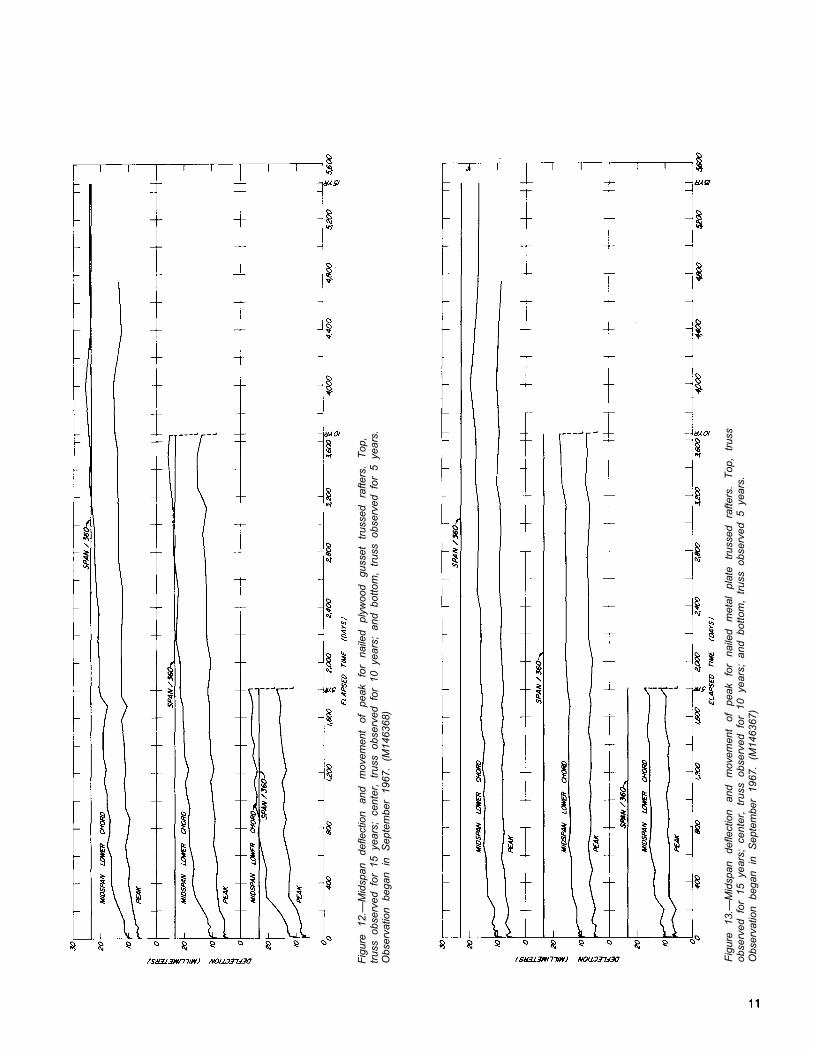
Fig
ure
12.—
Mid
span
de
flect
ion
and
mov
emen
t of
pe
ak
for
naile
d pl
ywoo
d gu
sset
tr
usse
d ra
fters
. T
op,
trus
s ob
serv
ed f
or 1
5 ye
ars;
cen
ter,
tru
ss o
bser
ved
for
10 y
ears
; an
d bo
ttom
, tr
uss
obse
rved
for
5 y
ears
.O
bser
vatio
n be
gan
in
Sep
tem
ber
1967
. (M
1463
68)
Fig
ure
13.—
Mid
span
de
flect
ion
and
mov
emen
t of
pe
ak
for
naile
d m
etal
pl
ate
trus
sed
rafte
rs.
Top
, tr
uss
obse
rved
for
15
year
s; c
ente
r, t
russ
obs
erve
d fo
r 10
yea
rs;
and
botto
m,
trus
s ob
serv
ed 5
yea
rs.
Obs
erva
tion
bega
n in
S
epte
mbe
r 19
67.
(M14
6367
)

Fig
ure
14.—
Mid
span
de
flect
ion
and
mov
emen
t of
pe
ak
for
toot
hed
met
al
plat
e tr
usse
d ra
fters
, T
op,
trus
s ob
serv
ed f
or 1
5 ye
ars;
cen
ter,
tru
ss o
bser
ved
for
10 y
ears
; an
d bo
ttom
, tr
uss
obse
rved
for
5 y
ears
.O
bser
vatio
n be
gan
in
Sep
tem
ber
1967
. (M
1463
69)
Fig
ure
15.—
Mid
span
de
flect
ion
and
mov
emen
t of
pe
ak
for
barb
ed
met
al
plat
e tr
usse
d ra
fters
. T
op,
trus
sob
serv
ed f
or 1
5 ye
ars;
cen
ter,
tru
ss o
bser
ved
for
10 y
ears
; an
d bo
ttom
, tr
uss
obse
rved
5 y
ears
,O
bser
vatio
n be
gan
in
Sep
tem
ber
1967
. (M
1463
70)

Fig
ure
16.—
Mid
span
de
flect
ion
and
mov
emen
t of
pe
ak
for
case
in-g
lued
pl
ywoo
d gu
sset
ed
trus
sed
rafte
rs.
Top
, tr
uss
obse
rved
for
15
year
s; c
ente
r, t
russ
obs
erve
d fo
r 10
yea
rs;
and
botto
m,
trus
sob
serv
ed f
or 5
yea
rs.
Obs
erva
tion
bega
n in
Sep
tem
ber
1967
. (M
1463
71)
Fig
ure
17.—
Mid
span
def
lect
ion
and
mov
emen
t of
pea
k fo
r tr
usse
d ra
fter
s w
ith p
lyw
ood
gu
ss
et
glue
dw
ith
phen
ol-r
esor
cino
l gl
ue
“A.”
T
op,
trus
s ob
serv
ed
for
15
year
s;
cent
er,
trus
s ob
serv
ed
for
10
year
s;an
d bo
ttom
, tr
uss
obse
rved
5
year
s.
Obs
erva
tion
bega
n in
S
epte
mbe
r 19
67.
(M14
6373
)
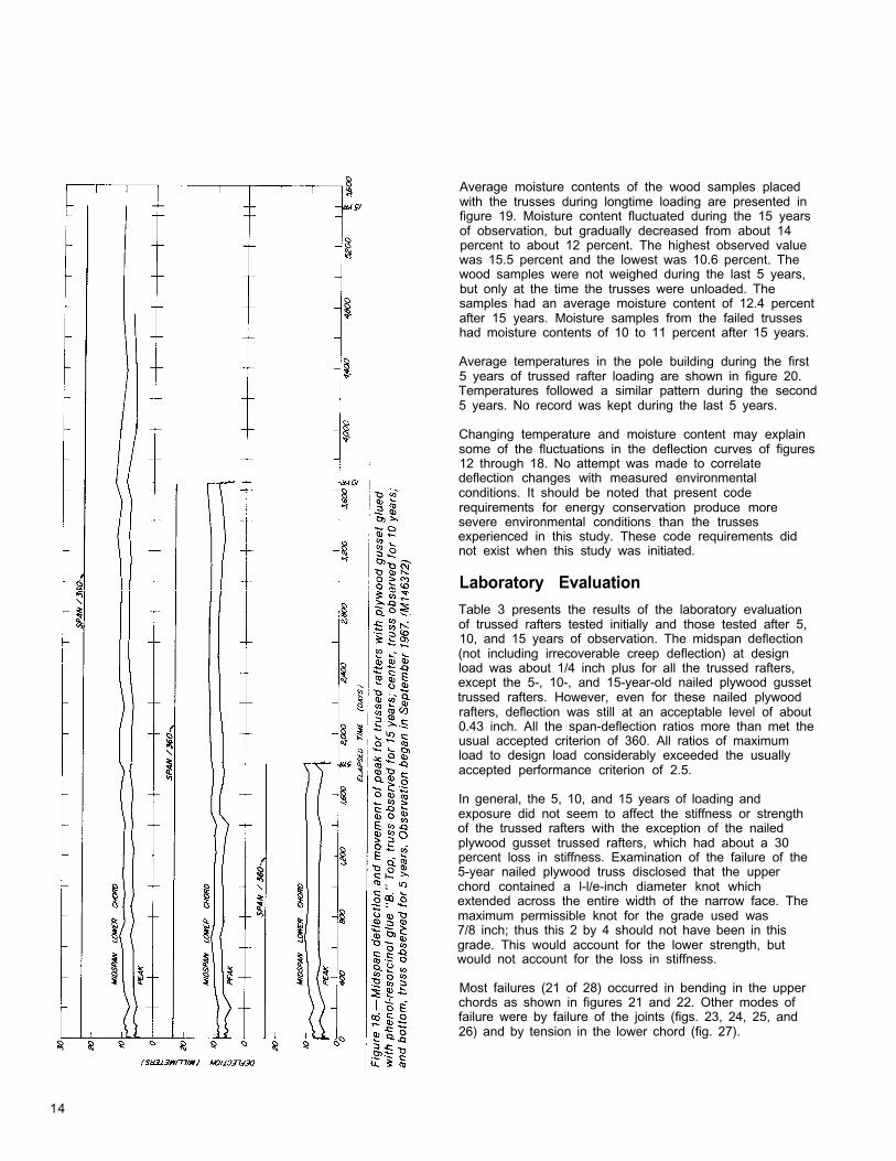
Average moisture contents of the wood samples placedwith the trusses during longtime loading are presented infigure 19. Moisture content fluctuated during the 15 yearsof observation, but gradually decreased from about 14percent to about 12 percent. The highest observed valuewas 15.5 percent and the lowest was 10.6 percent. Thewood samples were not weighed during the last 5 years,but only at the time the trusses were unloaded. Thesamples had an average moisture content of 12.4 percentafter 15 years. Moisture samples from the failed trusseshad moisture contents of 10 to 11 percent after 15 years.
Average temperatures in the pole building during the first5 years of trussed rafter loading are shown in figure 20.Temperatures followed a similar pattern during the second5 years. No record was kept during the last 5 years.
Changing temperature and moisture content may explainsome of the fluctuations in the deflection curves of figures12 through 18. No attempt was made to correlatedeflection changes with measured environmentalconditions. It should be noted that present coderequirements for energy conservation produce moresevere environmental conditions than the trussesexperienced in this study. These code requirements didnot exist when this study was initiated.
Laboratory Evaluation
Table 3 presents the results of the laboratory evaluationof trussed rafters tested initially and those tested after 5,10, and 15 years of observation. The midspan deflection(not including irrecoverable creep deflection) at designload was about 1/4 inch plus for all the trussed rafters,except the 5-, 10-, and 15-year-old nailed plywood gussettrussed rafters. However, even for these nailed plywoodrafters, deflection was still at an acceptable level of about0.43 inch. All the span-deflection ratios more than met theusual accepted criterion of 360. All ratios of maximumload to design load considerably exceeded the usuallyaccepted performance criterion of 2.5.
In general, the 5, 10, and 15 years of loading andexposure did not seem to affect the stiffness or strengthof the trussed rafters with the exception of the nailedplywood gusset trussed rafters, which had about a 30percent loss in stiffness. Examination of the failure of the5-year nailed plywood truss disclosed that the upperchord contained a l-l/e-inch diameter knot whichextended across the entire width of the narrow face. Themaximum permissible knot for the grade used was7/8 inch; thus this 2 by 4 should not have been in thisgrade. This would account for the lower strength, butwould not account for the loss in stiffness.
Most failures (21 of 28) occurred in bending in the upperchords as shown in figures 21 and 22. Other modes offailure were by failure of the joints (figs. 23, 24, 25, and26) and by tension in the lower chord (fig. 27).
14
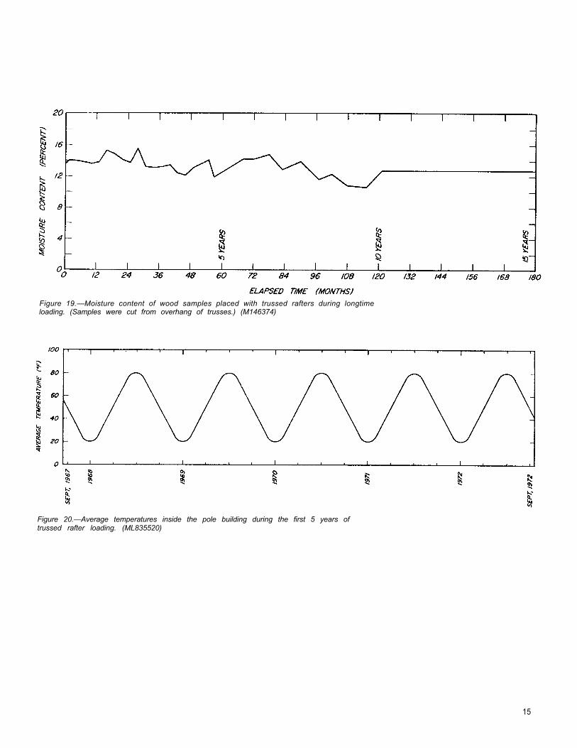
Figure 19.—Moisture content of wood samples placed with trussed rafters during longtimeloading. (Samples were cut from overhang of trusses.) (M146374)
Figure 20.—Average temperatures inside the pole building during the first 5 years oftrussed rafter loading. (ML835520)
15

Table 3.—Results of laboratory loading to maximum load of Douglas-fir trussed rafters
Gusset material ConnectorTrussed
rafterage
Total loadMidspan Span on truss
deflection at deflection at failuredesign dead ratio atplus live load design load Lower Upper
chord chord
In. � � � �Lb/ft� � � �
1/2-inch plywood,exterior grade
Galvanized sheet metal 1 -1/2-inch-long(20-gage) with annularly threadedpunched holes nails
Toothed metal trussplate (18-gagegalvanized sheetmetal)
—
Barbed metal trussplate (20-gagegalvanized sheetmetal)
—
1/2-inch plywood, Casein glue andexterior grade 4d nails
l/P-inch plywood, Phenol-resorcinol “A”exterior grade and 4d nails
1/2-inch plywood, Phenol-resorcinol “B”exterior grade and 4d nails
6d common nails Control5 years10 years15 years
0.29.43.42.39
1,160780800862
20202020
2563202219227
Control .29 1,160 20 2955 years .27 1,240 20 32510 years .32 1,050 20 29415 years .30 1,120 20 306
Control .23 1,4605 years .30 1,12010 years .33 1,02015 years .28 1,200
20202020
20202020
20202020
298305323301
Control .22 1,5305 years .30 1,12010 years .28 1,20015 years .28 1,200
269249300275
Control .24 1,4005 years .27 1,24010 years .24 1,40015 years .20 1.680
398285322327
Control .22 1,5305 years .23 1,46010 years .24 1,40015 years .20 1,680
20202020
20202020
324360296301
Control .23 1,4605 years .23 1,46010 years .24 1,40015 years .24 1,400
295299250270
Lower Upperchord chord
1111
1111
1111
1111
1111
1111
1111
4.93.94.24.4
5.76.25.65.9
5.75.96.25.8
5.25.95.85.3
7.65.56.26.6
6.26.95.75.8
5.75.74.85.2
Ratio of loadat failure todesign load
1 Design dead load was 20 lb per lineal ft on lower and upper chords. Design live load was 32 lb per lineal ft on the top chord. The pointof reference for deflection was over the center of the reactions. The distance from center to center of reactions was 27 ft 6 in. Thisdeflection does not include any irrecoverable deflection from longtime loading.
2 The span was 28 ft from outside to outside of bearing areas.
3 Broke at upper chord knot which was larger than allowed by the grading rules.
16

Figure PI.-Typical failure of trussed rafters in Figure 23.—Failure of control trussed rafter withupper chord between peak and compression nailed plywood gussets. Failure was at themember. (M 132865) lower chord splice. (M 132784)
Figure 22.—Typical failure of trussed rafter inupper chord over compression member.(M140589-1)
Figure 24.—Failure of 5-year-old barbed metal-plate gusset trussed rafter in heel joint.(M140589-9)
17
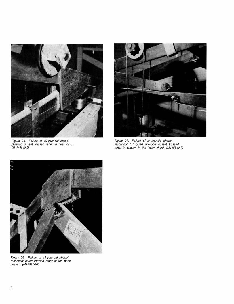
Figure 25.—Failure of 10-year-old nailedplywood gusset trussed rafter in heel joint.(M 145840-2)
Figure 27.—Failure of lo-year-old phenol-resorcinol “B” glued plywood gusset trussedrafter in tension in the lower chord. (M145840-7)
Figure 26.—Failure of 15-year-old phenol-resorcinol glued trussed rafter at the peakgusset. (M150974-7)
18

Conclusions Literature Cited
The following conclusions are based on data obtainedafter 15 years of longtime loading of trussed rafters. Oneshould keep in mind that environmental conditions in thisstudy were not as severe as trusses may experienceunder present code requirements.
1. All the trussed rafters deflected under load with time.The amount of deflection appears to be related to the jointrigidity, with ratios of total to initial deflection of:(a) three for the nailed plywood gusset trusses,(b) two and one-half for the metal plate gusset trusses,and(c) less than two for the nailed-glued gusset trusses.Most of the creep occured during early stages ofexposure. Deflection values are at an acceptable levelafter 15 years, based on a criterion for span divided by360 with the exception of the nailed plywood gussettrussed rafters.
2. There appears to be no appreciable effect uponstrength and stiffness as determined from laboratoryevaluation after 5, 10, and 15 years of exposure, with theexception of the nailed plywood gusset trussed rafterswhich had a 30 percent reduction in stiffness. All thetrussed rafters still meet acceptable short-timeperformance criteria.
Angleton, H. D. Nailed-plywood gusset roof trusses, 4/12and greater slopes, maximum—28 feet 8 inches. Mimeo.F-40. Purdue Univ., Agr. Exp. Sta., Lafayette, Ind.; 1960.
Feldburg, T.; Johansen, M. Deflection of trussed raftersunder alternating loading during a year. Inter. Concil. forBuilding Res. Studies and Documentations, WorkingCommission W 18—Timber Structures, Building Res. Inst.,Salburg, Denmark; June, 1976.
Luxford, R. F. Light wood trusses. Forest Prod. Lab. Rep.2113, Madison, Wis.; 1958.
Luxford, R. F.; Heyer, O. C. Glued and nailed roof trussesfor house construction. Forest Prod. Lab. Rep. 1992,Madison, Wis.; 1954.
Pneuman, F. C. King-post trusses with plywood gussetsone side. Tech. Bull. Douglas-Fir Plywood Assoc., Tech.Dep., Tacoma, Wash.; 1960.
Radcliffe, B. M.; Granum, H. A new low-pitched roof trusswith nail-glued connections. Agr. Exp. Sta. Bull. 617,Wood Res. Lab., Purdue Univ., Lafayette, Ind.; 1955a.
Radcliffe, B. M.; Granum, H.; Suddatth, S. K. The Purdue-Illinois nail-glued roof truss with pitch of 3:12 and 4:12 forspans of 24 feet 8 inches and 28 feet 8 inches. Agr. Exp.Sta. Bull. 629, Wood Res. Lab., Purdue Univ., Lafayette,Ind.; 1955b.
Radcliffe, B. M.; Sliker, Alan. Effect of variables onperformance of trussed rafters. Res. Rep. 21, Mich. StateUniv., Agr. Exp. Sta., East Lansing, Mich.; 1964.
Radcliffe, B. M.; Suddarth, S. K. The Purdue-Illinois nail-glued truss with a pitch of 2:12 for spans of 24 feet8 inches and 28 feet 8 inches. Agr. Exp. Sta. Bull. 621,Wood Res. Lab., Purdue Univ., Lafayette, Ind.; 1955c.
Suddarth, S. K.; Percival, D. H.; Comus, Q. B. Testing andanalysis of 4 X 2 parallel-chord metal-plate-connectedtrusses. Res. Rep. 81-1, Small Homes Council-BuildingResearch Council, Univ. of Ill., Urbana-Champaign, III.;1981.
Wilkinson, T. L. Moisture cycling of trussed rafter joints.Forest Serv. Res. Pap. FPL 67, Forest Prod. Lab.,Madison, Wis.; 1966.
Wilkinson, T. L. Longtime performance of trussed rafterswith different connection systems: 10-year evaluation.Forest Serv. Res. Pap. FPL 204 (revised), For. Prod. Lab.,Madson, Wis.; 1978.
2 . 5 - 4 / 8 4
U.S. GOVERNMENT PRINTING OFFICE: 1 9 8 4 6 5 4 0 2 5 4 0 3 6 19