
ITW Alpine -Trussed Rafter Guide - Irish Eco Homes€¦ · WATER TANK DETAILS Water Tank Support...
24
Trussed Rafter Guide Advancing timber fabrications through design : components : manufacture ALPINE www.itwalpine.co.uk MCL 005 T-GL
Transcript of ITW Alpine -Trussed Rafter Guide - Irish Eco Homes€¦ · WATER TANK DETAILS Water Tank Support...
Trussed Rafter Guide
Advancing timber fabrications through design : components : manufacture
ALPINE
www.itwalpine.co.uk MCL 005T-GL
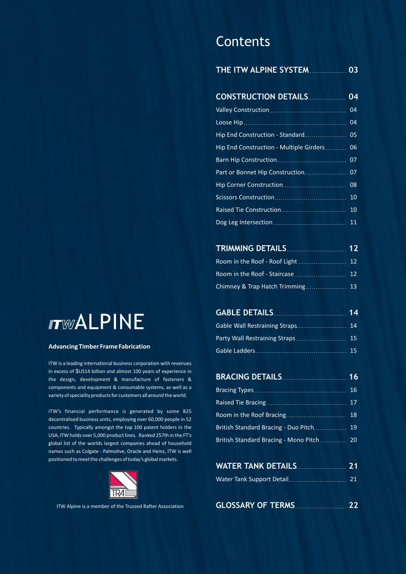
THE ITW ALPINE SYSTEM
CONSTRUCTION DETAILS
Valley Construction
Loose Hip
Hip End Construction - Standard
Hip End Construction - Multiple Girders
Barn Hip Construction
Part or Bonnet Hip Construction
Hip Corner Construction
Scissors Construction
Raised Tie Construction
Dog Leg Intersection
TRIMMING DETAILS
Room in the Roof - Roof Light
Room in the Roof - Staircase
Chimney & Trap Hatch Trimming
GABLE DETAILS
Gable Wall Restraining Straps
Party Wall Restraining Straps
Gable Ladders
BRACING DETAILS
Bracing Types
Raised Tie Bracing
Room in the Roof Bracing
British Standard Bracing - Duo Pitch
British Standard Bracing - Mono Pitch
WATER TANK DETAILS
Water Tank Support Detail
GLOSSARY OF TERMS
Contents
03
04
04
04
05
06
07
07
08
10
10
11
12
12
12
13
14
14
15
15
16
16
17
18
19
20
21
21
22ITW Alpine is a member of the Trussed Rafter Association
Advancing Timber Frame Fabrication
ITW is a leading international business corporation with revenues
in excess of $US14 billion and almost 100 years of experience in
the design, development & manufacture of fasteners &
components and equipment & consumable systems, as well as a
variety of speciality products for customers all around the world.
ITW’s financial performance is generated by some 825
decentralised business units, employing over 60,000 people in 52
countries. Typically amongst the top 100 patent holders in the
USA, ITW holds over 5,000 product lines. Ranked 257th in the FT’s
global list of the worlds largest companies ahead of household
names such as Colgate - Palmolive, Oracle and Heinz, ITW is well
positioned to meet the challenges of today’s global markets.
ALPINE
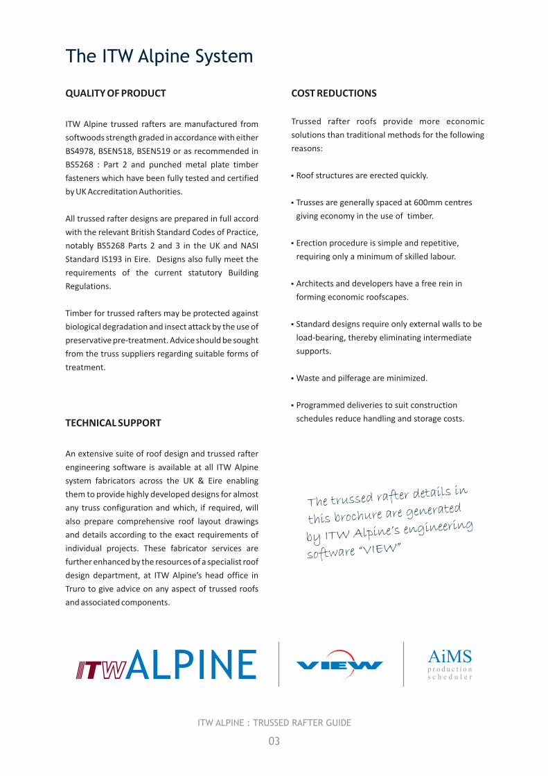
QUALITY OF PRODUCT
ITW Alpine trussed rafters are manufactured from
softwoods strength graded in accordance with either
BS4978, BSEN518, BSEN519 or as recommended in
BS5268 : Part 2 and punched metal plate timber
fasteners which have been fully tested and certified
by UK Accreditation Authorities.
All trussed rafter designs are prepared in full accord
with the relevant British Standard Codes of Practice,
notably BS5268 Parts 2 and 3 in the UK and NASI
Standard IS193 in Eire. Designs also fully meet the
requirements of the current statutory Building
Regulations.
Timber for trussed rafters may be protected against
biological degradation and insect attack by the use of
preservative pre-treatment. Advice should be sought
from the truss suppliers regarding suitable forms of
treatment.
TECHNICAL SUPPORT
An extensive suite of roof design and trussed rafter
engineering software is available at all ITW Alpine
system fabricators across the UK & Eire enabling
them to provide highly developed designs for almost
any truss configuration and which, if required, will
also prepare comprehensive roof layout drawings
and details according to the exact requirements of
individual projects. These fabricator services are
further enhanced by the resources of a specialist roof
design department, at ITW Alpine’s head office in
Truro to give advice on any aspect of trussed roofs
and associated components.
The trussed rafter details in
this brochure are generated
by ITW Alpine’s engineering
software “VIEW”
ALPINE
COST REDUCTIONS
Trussed rafter roofs provide more economic
solutions than traditional methods for the following
reasons:
3Roof structures are erected quickly.
3Trusses are generally spaced at 600mm centres
giving economy in the use of timber.
3Erection procedure is simple and repetitive,
requiring only a minimum of skilled labour.
3Architects and developers have a free rein in
forming economic roofscapes.
3Standard designs require only external walls to be
load-bearing, thereby eliminating intermediate
supports.
3Waste and pilferage are minimized.
3Programmed deliveries to suit construction
schedules reduce handling and storage costs.
AiMSp r o d u c t i o ns c h e d u l e r
The ITW Alpine System
03
ITW ALPINE : TRUSSED RAFTER GUIDE
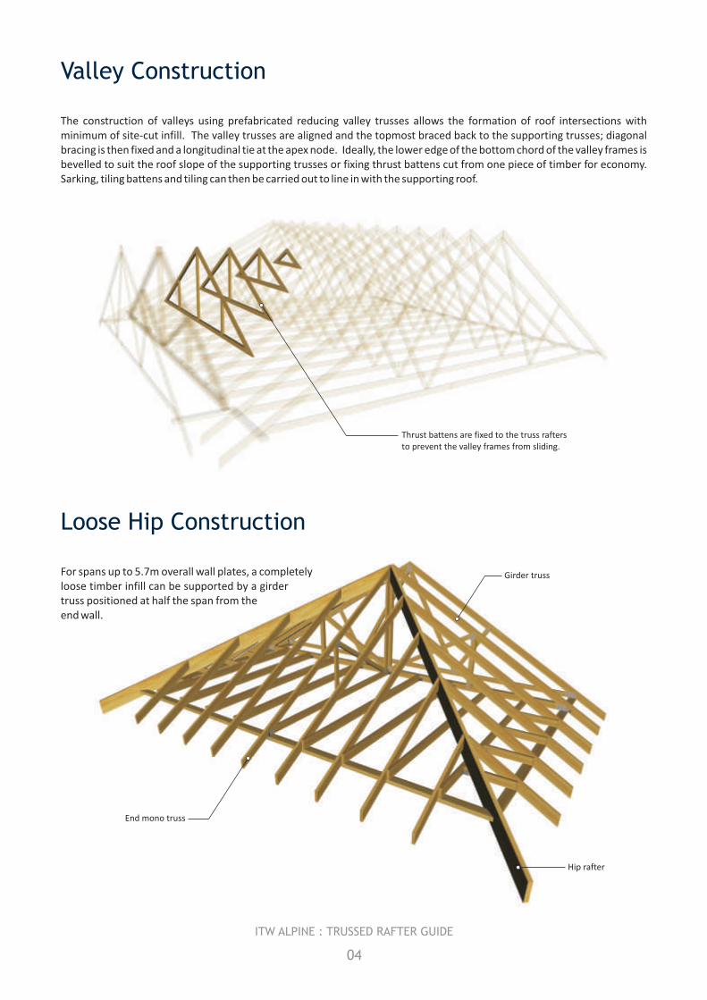
End mono truss
Girder truss
Hip rafter
Valley Construction
The construction of valleys using prefabricated reducing valley trusses allows the formation of roof intersections with minimum of site-cut infill. The valley trusses are aligned and the topmost braced back to the supporting trusses; diagonal bracing is then fixed and a longitudinal tie at the apex node. Ideally, the lower edge of the bottom chord of the valley frames is bevelled to suit the roof slope of the supporting trusses or fixing thrust battens cut from one piece of timber for economy. Sarking, tiling battens and tiling can then be carried out to line in with the supporting roof.
For spans up to 5.7m overall wall plates, a completely loose timber infill can be supported by a girder truss positioned at half the span from the end wall.
Loose Hip Construction
04
ITW ALPINE : TRUSSED RAFTER GUIDE
Thrust battens are fixed to the truss rafters to prevent the valley frames from sliding.
Hip End Construction - Standard
05
ITW ALPINE : TRUSSED RAFTER GUIDE
Hip girder
Intermediate tru
sses
Hip rafte
r
Side jack rafte
rs
Mono-pitch trusses
End jack rafters
Std. trusse
s
Hip girder
Jack rafter
Hip rafterbirdsmouthedover wallplate
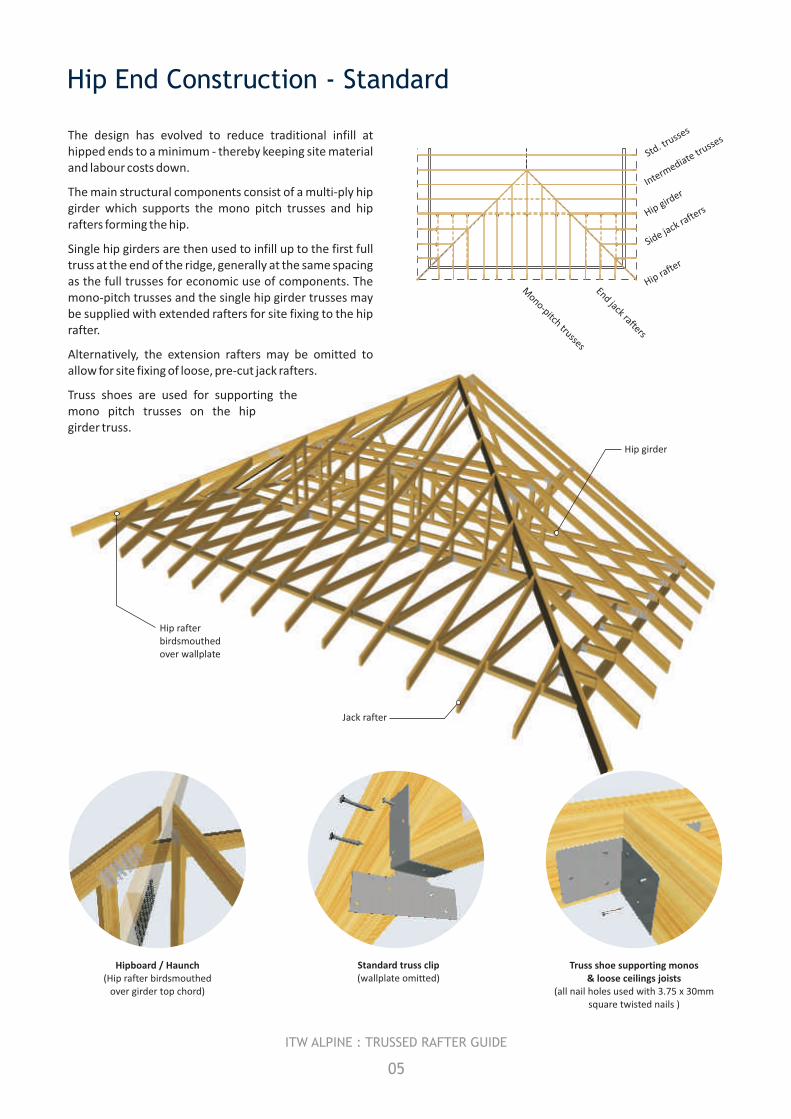
The design has evolved to reduce traditional infill at hipped ends to a minimum - thereby keeping site material and labour costs down.
The main structural components consist of a multi-ply hip girder which supports the mono pitch trusses and hip rafters forming the hip.
Single hip girders are then used to infill up to the first full truss at the end of the ridge, generally at the same spacing as the full trusses for economic use of components. The mono-pitch trusses and the single hip girder trusses may be supplied with extended rafters for site fixing to the hip rafter.
Alternatively, the extension rafters may be omitted to allow for site fixing of loose, pre-cut jack rafters.
Truss shoes are used for supporting the mono pitch trusses on the hip girder truss.
Hipboard / Haunch(Hip rafter birdsmouthed
over girder top chord)
Standard truss clip(wallplate omitted)
Truss shoe supporting monos & loose ceilings joists
square twisted nails )(all nail holes used with 3.75 x 30mm
Hip End Construction - Multiple Girders
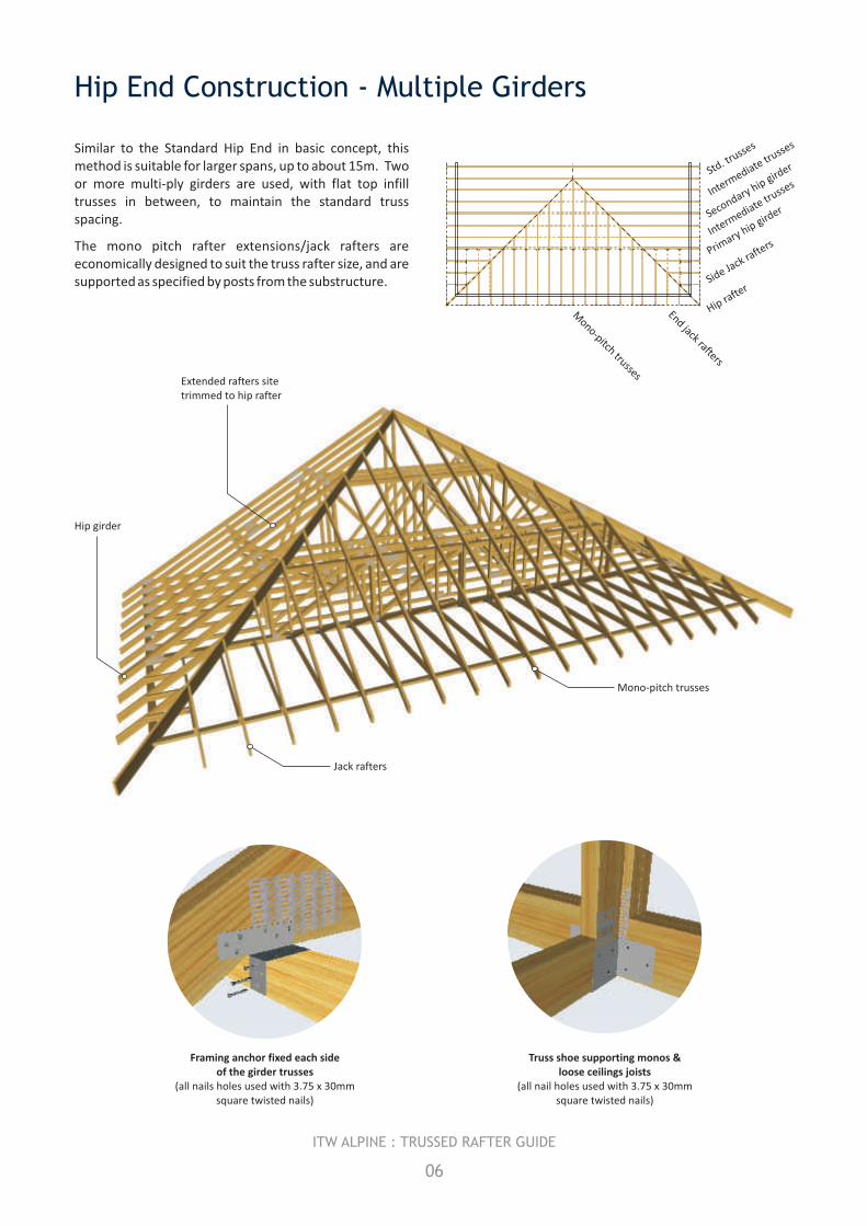
Similar to the Standard Hip End in basic concept, this method is suitable for larger spans, up to about 15m. Two or more multi-ply girders are used, with flat top infill trusses in between, to maintain the standard truss spacing.
The mono pitch rafter extensions/jack rafters are economically designed to suit the truss rafter size, and are supported as specified by posts from the substructure.
Truss shoe supporting monos & loose ceilings joists
square twisted nails)(all nail holes used with 3.75 x 30mm
Primary hip gird
erSecondary hip girder
Hip rafte
rSide Ja
ck rafte
rs
Mono-pitch trusses
Std. trusse
s
Intermediate tru
sses
Intermediate tru
sses
End jack rafters
06
ITW ALPINE : TRUSSED RAFTER GUIDE
Framing anchor fixed each side of the girder trusses
(all nails holes used with 3.75 x 30mm square twisted nails)
Hip girder
Extended rafters site trimmed to hip rafter
Jack rafters
Mono-pitch trusses
Mono-pitch trusses
Exposed triangle at end of ridged roof
Compound ormulti-ply truss
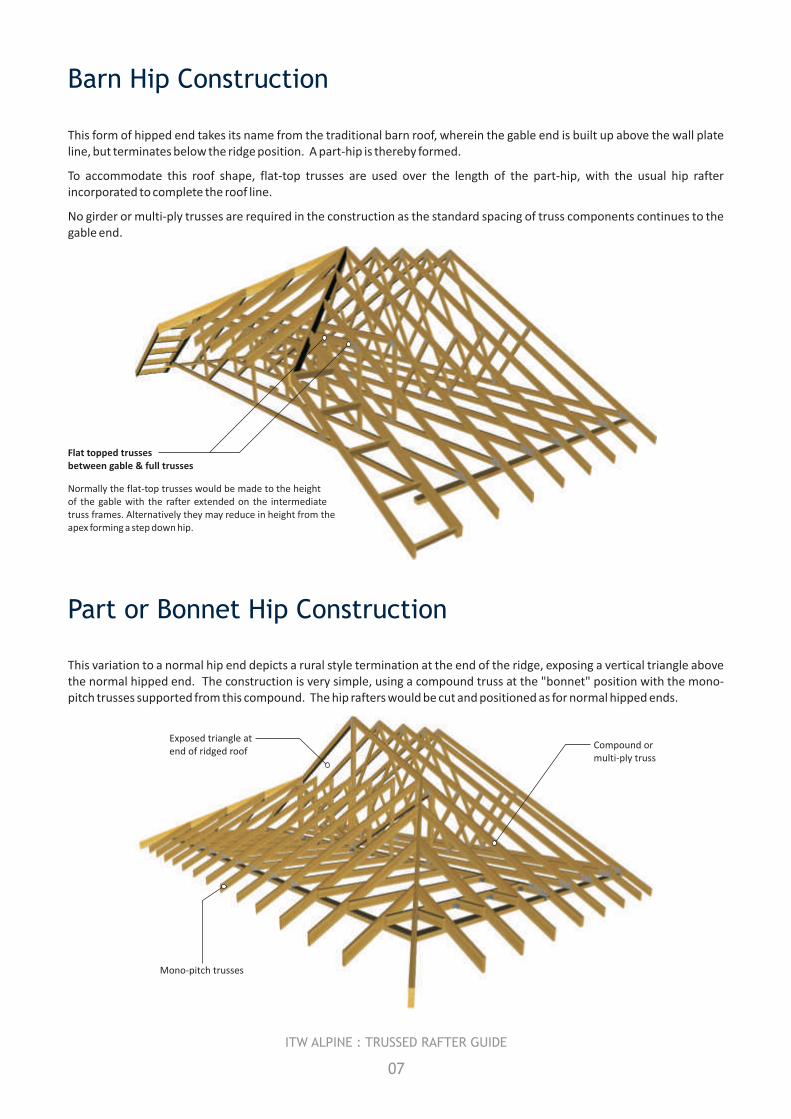
Barn Hip Construction
Part or Bonnet Hip Construction
This form of hipped end takes its name from the traditional barn roof, wherein the gable end is built up above the wall plate line, but terminates below the ridge position. A part-hip is thereby formed.
To accommodate this roof shape, flat-top trusses are used over the length of the part-hip, with the usual hip rafter incorporated to complete the roof line.
No girder or multi-ply trusses are required in the construction as the standard spacing of truss components continues to the gable end.
This variation to a normal hip end depicts a rural style termination at the end of the ridge, exposing a vertical triangle above the normal hipped end. The construction is very simple, using a compound truss at the "bonnet" position with the mono-pitch trusses supported from this compound. The hip rafters would be cut and positioned as for normal hipped ends.
Normally the flat-top trusses would be made to the height of the gable with the rafter extended on the intermediate truss frames. Alternatively they may reduce in height from the apex forming a step down hip.
Flat topped trusses between gable & full trusses
07
ITW ALPINE : TRUSSED RAFTER GUIDE
Mono-pitch trusses
End jack rafters
Howe girder
Mono Valley set
Secondary hip girder
Primary hip gird
er
Hip rafte
r
Side jack rafte
rs
Std. trusse
s
Intermediate tru
sses
Mono valley set
08
ITW ALPINE : TRUSSED RAFTER GUIDE
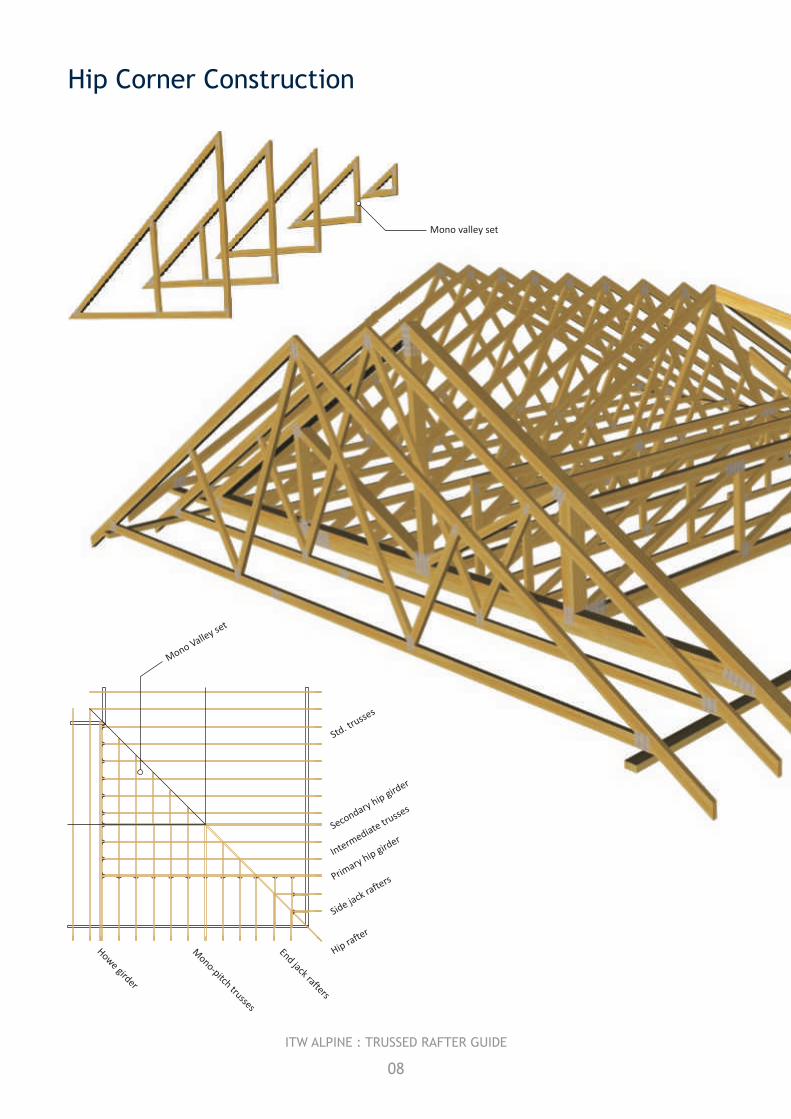
Hip ConstructionCorner
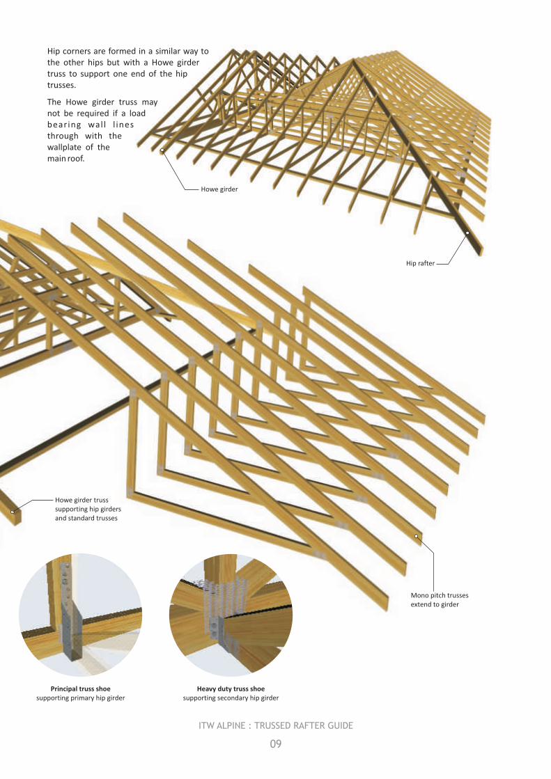
Hip corners are formed in a similar way to the other hips but with a Howe girder truss to support one end of the hip trusses.
The Howe girder truss may not be required if a load bearing wal l l ines through with the wallplate of the main roof.
Hip rafter
Mono pitch trusses extend to girder
Howe girder truss supporting hip girders and standard trusses
09
ITW ALPINE : TRUSSED RAFTER GUIDE
Howe girder
Heavy duty truss shoe supporting secondary hip girder
Principal truss shoe supporting primary hip girder
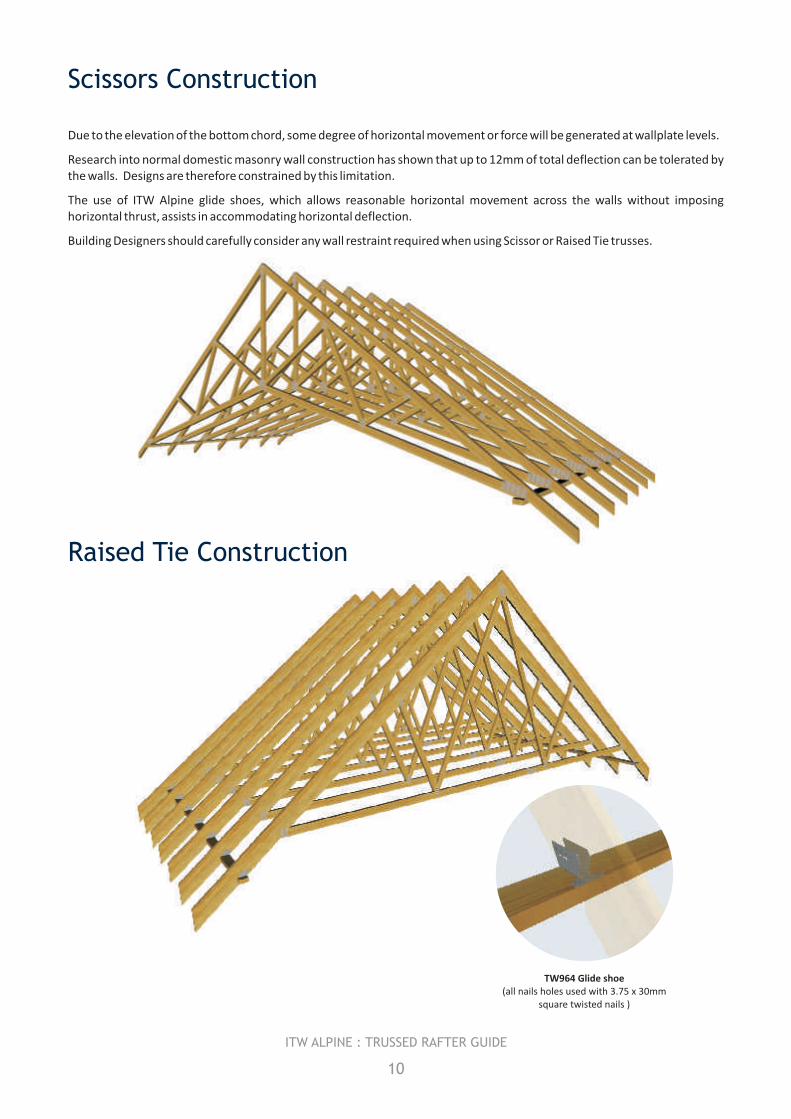
Scissors Construction
Raised Tie Construction
Due to the elevation of the bottom chord, some degree of horizontal movement or force will be generated at wallplate levels.
Research into normal domestic masonry wall construction has shown that up to 12mm of total deflection can be tolerated by the walls. Designs are therefore constrained by this limitation.
The use of ITW Alpine glide shoes, which allows reasonable horizontal movement across the walls without imposing horizontal thrust, assists in accommodating horizontal deflection.
Building Designers should carefully consider any wall restraint required when using Scissor or Raised Tie trusses.
10
ITW ALPINE : TRUSSED RAFTER GUIDE
TW964 Glide shoe
square twisted nails )
(all nails holes used with 3.75 x 30mm
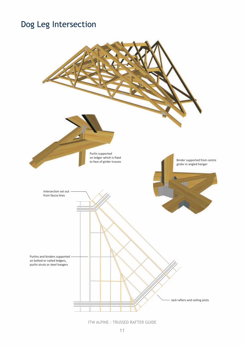
Dog Leg Intersection
11
ITW ALPINE : TRUSSED RAFTER GUIDE
Binder supported from centre girder in angled hanger
Purlin supportedon ledger which is fixedto face of girder trusses
Intersection set out from fascia lines
Purlins and binders supported on bolted or nailed ledgers, purlin struts or steel hangers
Jack rafters and ceiling joists
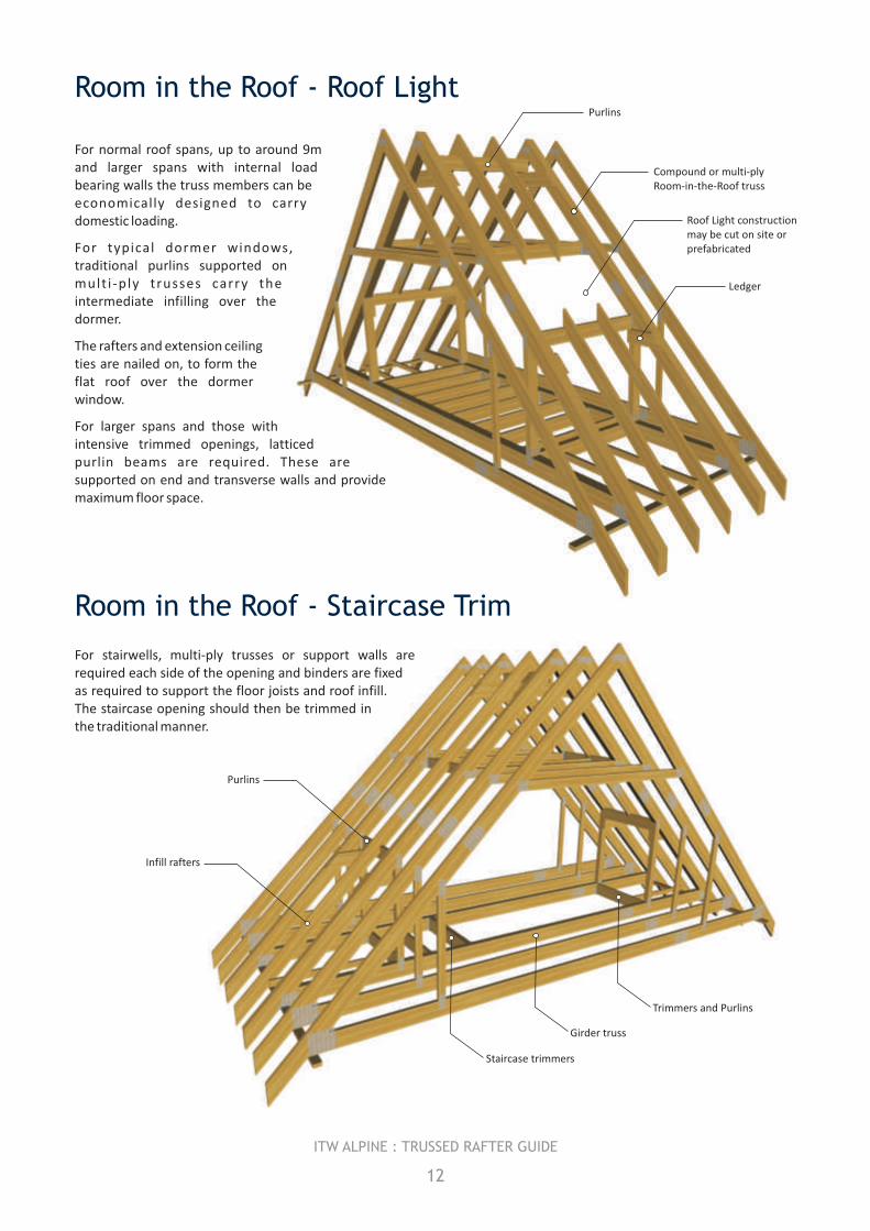
For stairwells, multi-ply trusses or support walls are required each side of the opening and binders are fixed as required to support the floor joists and roof infill. The staircase opening should then be trimmed in the traditional manner.
Purlins
Girder truss
Infill rafters
Staircase trimmers
Trimmers and Purlins
Purlins
Roof Light constructionmay be cut on site orprefabricated
Compound or multi-ply Room-in-the-Roof truss
Ledger
For normal roof spans, up to around 9m and larger spans with internal load bearing walls the truss members can be economically designed to carry domestic loading.
For typical dormer windows, traditional purlins supported on mult i -ply trusses carry the intermediate infilling over the dormer.
The rafters and extension ceiling ties are nailed on, to form the flat roof over the dormer window.
For larger spans and those with intensive trimmed openings, latticed purlin beams are required. These are supported on end and transverse walls and provide maximum floor space.
Room in the Roof - Roof Light
Room in the Roof - Staircase Trim
12
ITW ALPINE : TRUSSED RAFTER GUIDE
Trap hatch detail(rafters / webs omitted for clarity)
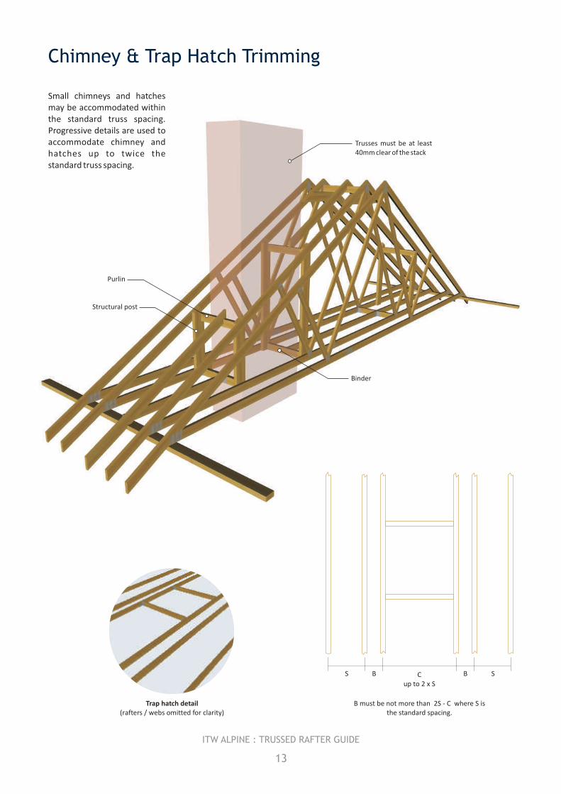
Chimney & Trap Hatch Trimming
B must be not more than 2S - C where S is the standard spacing.
Trusses must be at least 40mm clear of the stack
Binder
Purlin
Structural post
Small chimneys and hatches may be accommodated within the standard truss spacing. Progressive details are used to accommodate chimney and hatches up to twice the standard truss spacing.
13
ITW ALPINE : TRUSSED RAFTER GUIDE
B BS SC up to 2 x S
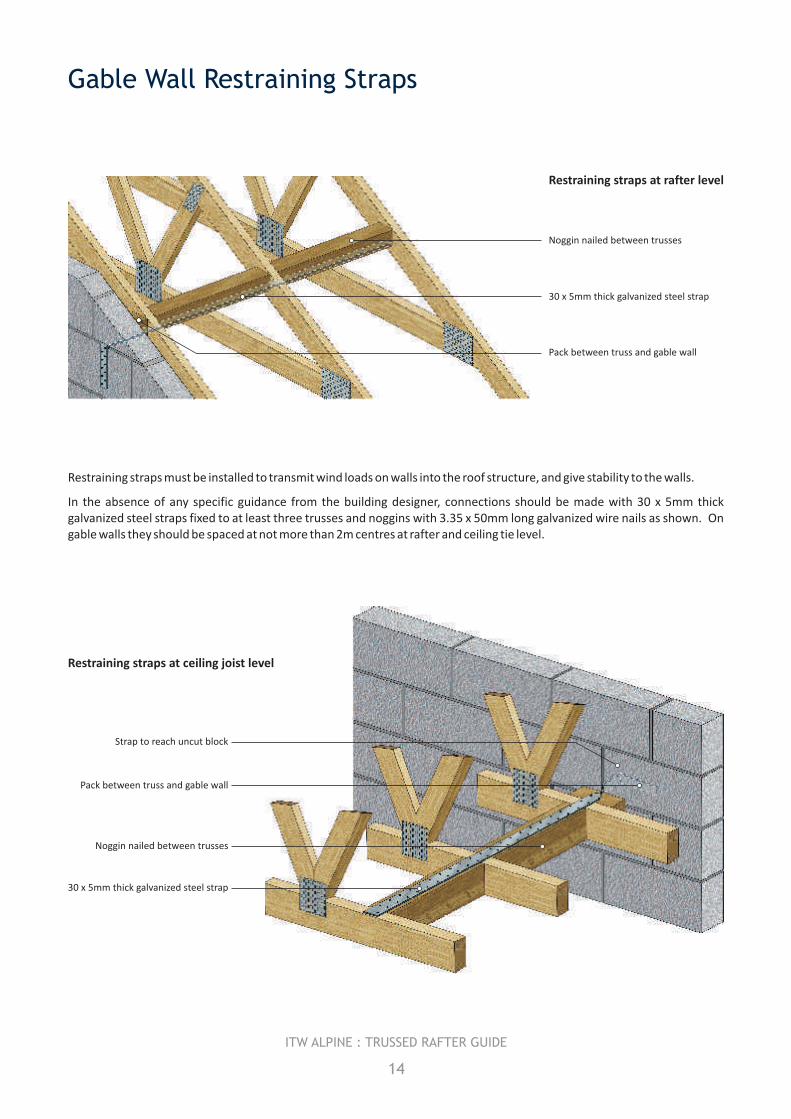
Noggin nailed between trusses
30 x 5mm thick galvanized steel strap
Restraining straps at rafter level
Pack between truss and gable wall
Strap to reach uncut block
Noggin nailed between trusses
30 x 5mm thick galvanized steel strap
Restraining straps at ceiling joist level
Pack between truss and gable wall
Gable Wall Restraining Straps
14
ITW ALPINE : TRUSSED RAFTER GUIDE
Restraining straps must be installed to transmit wind loads on walls into the roof structure, and give stability to the walls.
In the absence of any specific guidance from the building designer, connections should be made with 30 x 5mm thick galvanized steel straps fixed to at least three trusses and noggins with 3.35 x 50mm long galvanized wire nails as shown. On gable walls they should be spaced at not more than 2m centres at rafter and ceiling tie level.
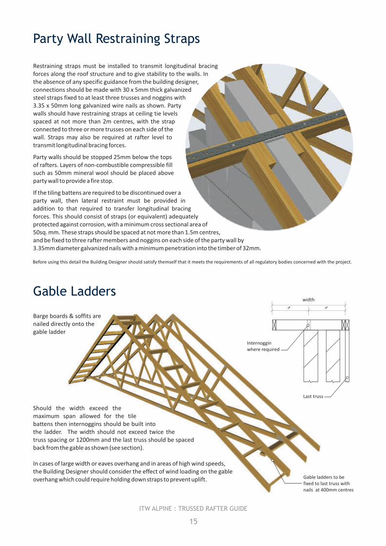
Restraining straps must be installed to transmit longitudinal bracing forces along the roof structure and to give stability to the walls. In the absence of any specific guidance from the building designer, connections should be made with 30 x 5mm thick galvanized steel straps fixed to at least three trusses and noggins with 3.35 x 50mm long galvanized wire nails as shown. Party walls should have restraining straps at ceiling tie levels spaced at not more than 2m centres, with the strap connected to three or more trusses on each side of the wall. Straps may also be required at rafter level to transmit longitudinal bracing forces.
Party walls should be stopped 25mm below the tops of rafters. Layers of non-combustible compressible fill such as 50mm mineral wool should be placed above party wall to provide a fire stop.
If the tiling battens are required to be discontinued over a party wall, then lateral restraint must be provided in addition to that required to transfer longitudinal bracing forces. This should consist of straps (or equivalent) adequately protected against corrosion, with a minimum cross sectional area of 50sq. mm. These straps should be spaced at not more than 1.5m centres, and be fixed to three rafter members and noggins on each side of the party wall by 3.35mm diameter galvanized nails with a minimum penetration into the timber of 32mm.
Party Wall Restraining Straps
Gable Ladders
Should the width exceed the maximum span allowed for the tile battens then internoggins should be built into the ladder. The width should not exceed twice the truss spacing or 1200mm and the last truss should be spaced back from the gable as shown (see section).
In cases of large width or eaves overhang and in areas of high wind speeds, the Building Designer should consider the effect of wind loading on the gable overhang which could require holding down straps to prevent uplift. Gable ladders to be
fixed to last truss with nails at 400mm centres
Barge boards & soffits are nailed directly onto the gable ladder
width
Last truss
Internoggin where required
15
ITW ALPINE : TRUSSED RAFTER GUIDE
Before using this detail the Building Designer should satisfy themself that it meets the requirements of all regulatory bodies concerned with the project.
Bracing Types
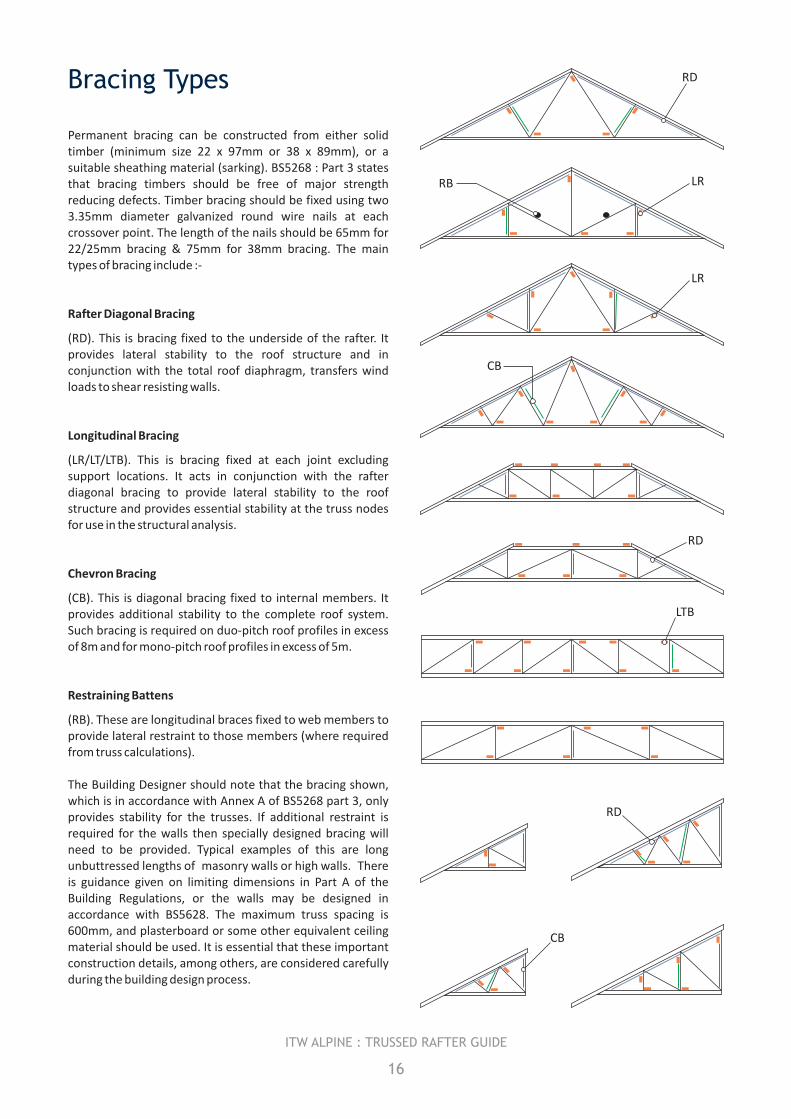
Permanent bracing can be constructed from either solid timber (minimum size 22 x 97mm or 38 x 89mm), or a suitable sheathing material (sarking). BS5268 : Part 3 states that bracing timbers should be free of major strength reducing defects. Timber bracing should be fixed using two 3.35mm diameter galvanized round wire nails at each crossover point. The length of the nails should be 65mm for 22/25mm bracing & 75mm for 38mm bracing. The main types of bracing include :-
Rafter Diagonal Bracing
(RD). This is bracing fixed to the underside of the rafter. It provides lateral stability to the roof structure and in conjunction with the total roof diaphragm, transfers wind loads to shear resisting walls.
Longitudinal Bracing
(LR/LT/LTB). This is bracing fixed at each joint excluding support locations. It acts in conjunction with the rafter diagonal bracing to provide lateral stability to the roof structure and provides essential stability at the truss nodes for use in the structural analysis.
Chevron Bracing
(CB). This is diagonal bracing fixed to internal members. It provides additional stability to the complete roof system. Such bracing is required on duo-pitch roof profiles in excess of 8m and for mono-pitch roof profiles in excess of 5m.
Restraining Battens
(RB). These are longitudinal braces fixed to web members to provide lateral restraint to those members (where required from truss calculations).
The Building Designer should note that the bracing shown, which is in accordance with Annex A of BS5268 part 3, only provides stability for the trusses. If additional restraint is required for the walls then specially designed bracing will need to be provided. Typical examples of this are long unbuttressed lengths of masonry walls or high walls. There is guidance given on limiting dimensions in Part A of the Building Regulations, or the walls may be designed in accordance with BS5628. The maximum truss spacing is 600mm, and plasterboard or some other equivalent ceiling material should be used. It is essential that these important construction details, among others, are considered carefully during the building design process.
16
ITW ALPINE : TRUSSED RAFTER GUIDE
RD
LRRB
LR
CB
RD
LTB
RD
CB
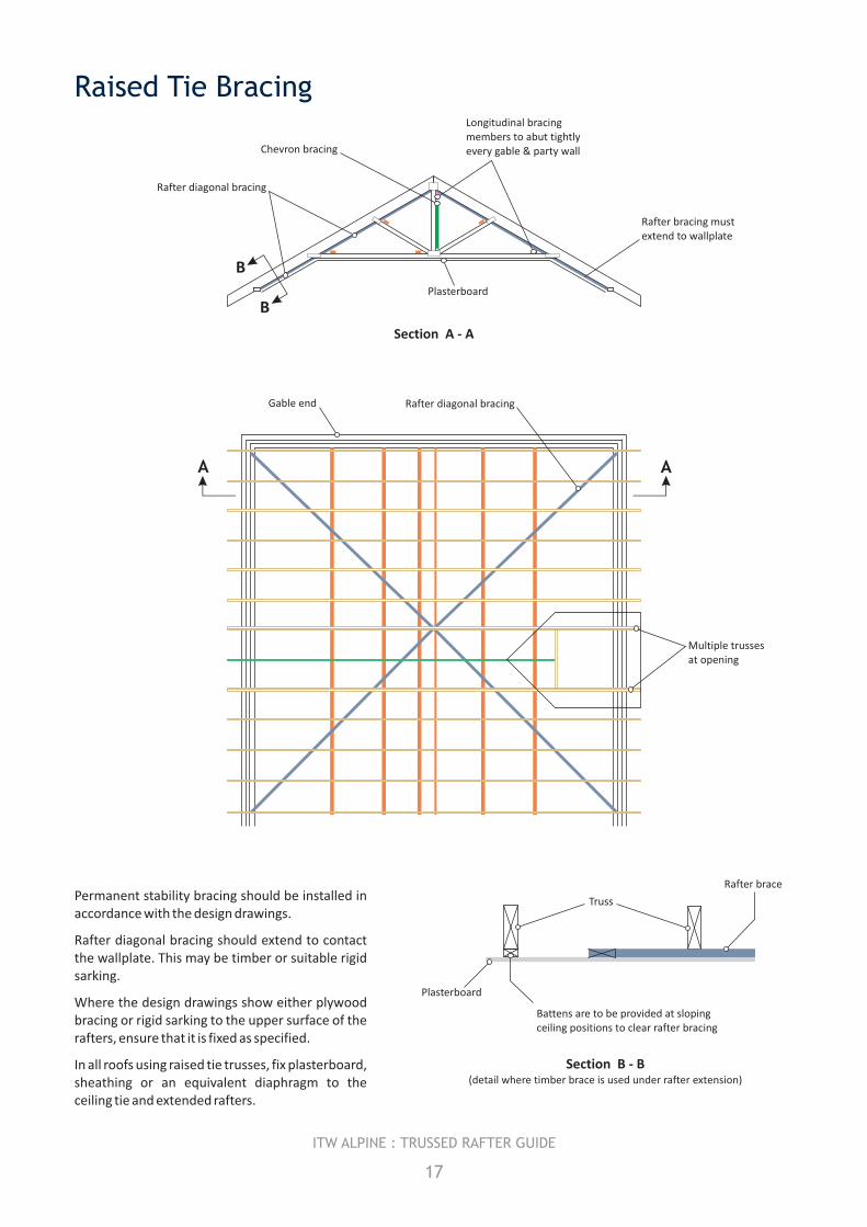
Raised Tie Bracing
Section A - A
Permanent stability bracing should be installed in accordance with the design drawings.
Rafter diagonal bracing should extend to contact the wallplate. This may be timber or suitable rigid sarking.
Where the design drawings show either plywood bracing or rigid sarking to the upper surface of the rafters, ensure that it is fixed as specified.
In all roofs using raised tie trusses, fix plasterboard, sheathing or an equivalent diaphragm to the ceiling tie and extended rafters.
17
ITW ALPINE : TRUSSED RAFTER GUIDE
Rafter diagonal bracing
Chevron bracing
Longitudinal bracingmembers to abut tightlyevery gable & party wall
Plasterboard
Rafter bracing mustextend to wallplate
B
B
Rafter diagonal bracingGable end
A A
Multiple trussesat opening
Truss
Rafter brace
Plasterboard
Battens are to be provided at slopingceiling positions to clear rafter bracing
Section B - B(detail where timber brace is used under rafter extension)
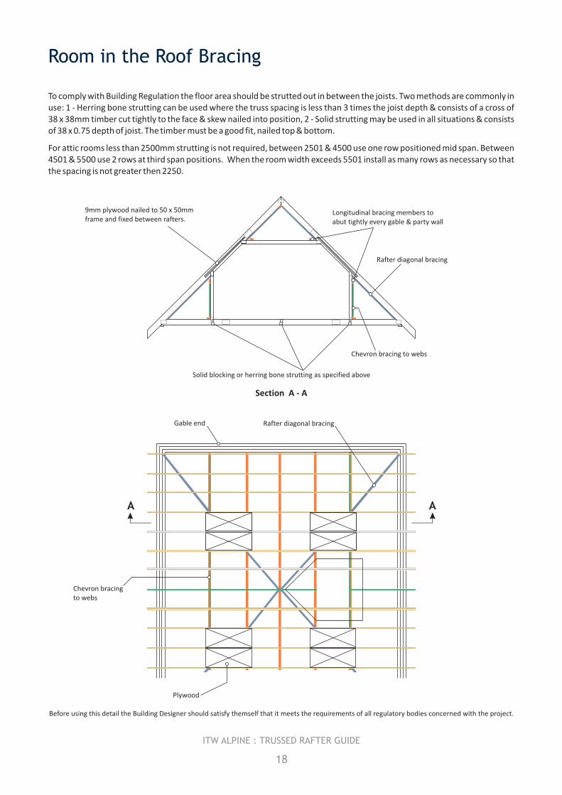
To comply with Building Regulation the floor area should be strutted out in between the joists. Two methods are commonly in use: 1 - Herring bone strutting can be used where the truss spacing is less than 3 times the joist depth & consists of a cross of 38 x 38mm timber cut tightly to the face & skew nailed into position, 2 - Solid strutting may be used in all situations & consists of 38 x 0.75 depth of joist. The timber must be a good fit, nailed top & bottom.
For attic rooms less than 2500mm strutting is not required, between 2501 & 4500 use one row positioned mid span. Between 4501 & 5500 use 2 rows at third span positions. When the room width exceeds 5501 install as many rows as necessary so that the spacing is not greater then 2250.
Room in the Roof Bracing
Section A - A
18
ITW ALPINE : TRUSSED RAFTER GUIDE
Rafter diagonal bracing
Longitudinal bracing members to abut tightly every gable & party wall
Chevron bracing to webs
Solid blocking or herring bone strutting as specified above
9mm plywood nailed to 50 x 50mm frame and fixed between rafters.
Rafter diagonal bracing
Chevron bracing to webs
Gable end
Plywood
A A
Before using this detail the Building Designer should satisfy themself that it meets the requirements of all regulatory bodies concerned with the project.
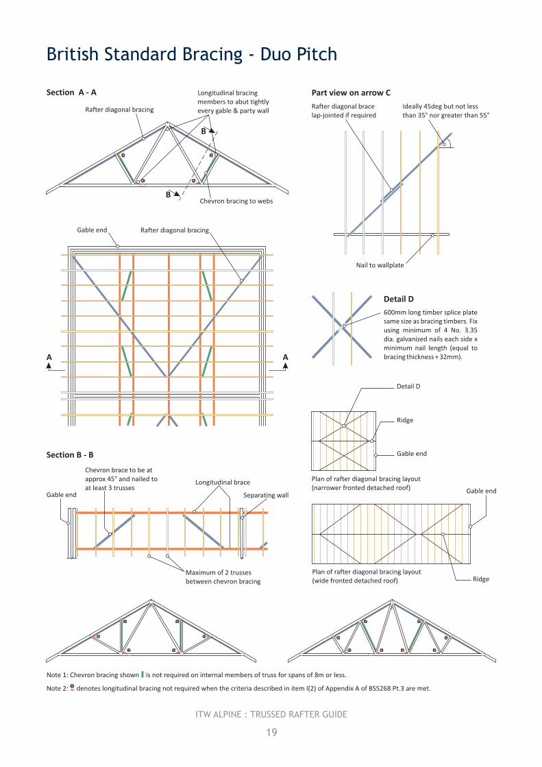
British Standard Bracing - Duo Pitch
Note 1: Chevron bracing shown is not required on internal members of truss for spans of 8m or less.
Note 2: denotes longitudinal bracing not required when the criteria described in item l(2) of Appendix A of BS5268 Pt.3 are met.
Detail D
Ridge
Ridge
Gable end
Gable end
Plan of rafter diagonal bracing layout(wide fronted detached roof)
Plan of rafter diagonal bracing layout(narrower fronted detached roof)
Rafter diagonal bracing
Longitudinal bracingmembers to abut tightlyevery gable & party wall
Chevron bracing to webs
Section A - A
B
B
Rafter diagonal brace lap-jointed if required
Ideally 45deg but not less than 35° nor greater than 55°
Nail to wallplate
Part view on arrow C
600mm long timber splice plate same size as bracing timbers. Fix using minimum of 4 No. 3.35 dia. galvanized nails each side x minimum nail length (equal to bracing thickness + 32mm).
Detail D
Chevron brace to be at approx 45° and nailed to at least 3 trusses
Gable end
Longitudinal brace
Separating wall
Maximum of 2 trussesbetween chevron bracing
Section B - B
19
ITW ALPINE : TRUSSED RAFTER GUIDE
Rafter diagonal bracingGable end
AA
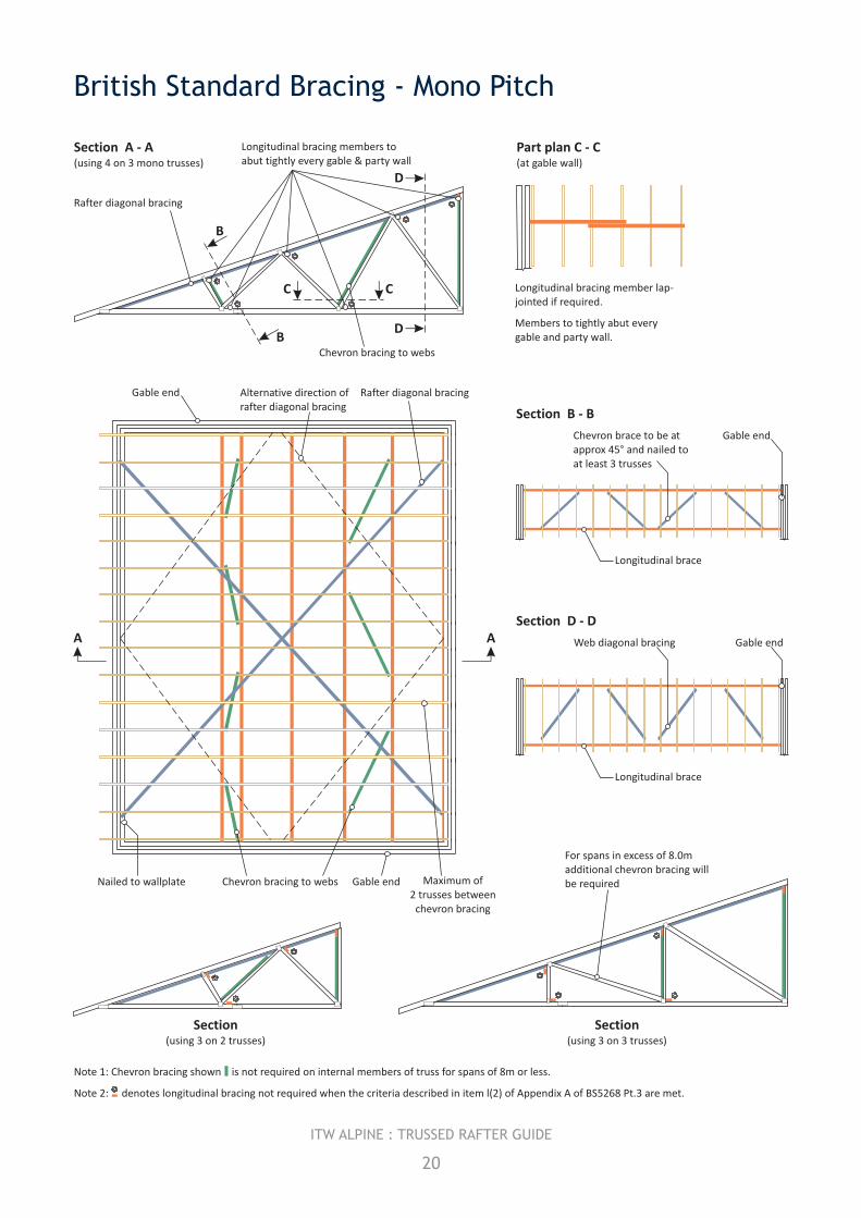
British Standard Bracing - Mono Pitch
Longitudinal bracing member lap-jointed if required.
Members to tightly abut every gable and party wall.
Part plan C - C (at gable wall)
Section (using 3 on 2 trusses)
Rafter diagonal bracing
Longitudinal bracing members to abut tightly every gable & party wall
Chevron bracing to webs
Section A - A(using 4 on 3 mono trusses)
B
B
C C
D
D
Section B - B
Chevron brace to be at approx 45° and nailed to at least 3 trusses
Gable end
Longitudinal brace
Section D - D
Gable endWeb diagonal bracing
Longitudinal brace
Rafter diagonal bracingGable end
A A
Gable end Maximum of 2 trusses between
chevron bracing
Nailed to wallplate Chevron bracing to webs
Alternative direction ofrafter diagonal bracing
For spans in excess of 8.0m additional chevron bracing will be required
Section (using 3 on 3 trusses)
20
ITW ALPINE : TRUSSED RAFTER GUIDE
Note 1: Chevron bracing shown is not required on internal members of truss for spans of 8m or less.
Note 2: denotes longitudinal bracing not required when the criteria described in item l(2) of Appendix A of BS5268 Pt.3 are met.
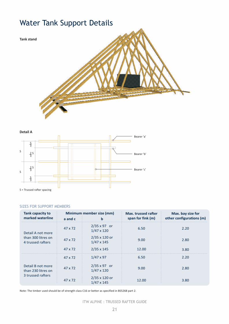
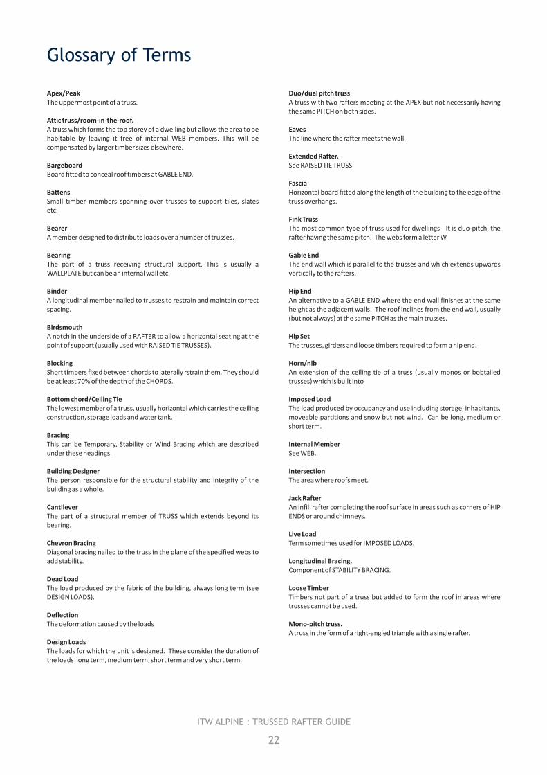
Water Tank Support Details
Tank capacity tomarked waterline
Detail A not morethan 300 litres on4 trussed rafters
Detail B not morethan 230 litres on3 trussed rafters
Minimum member size (mm)
a and c b
47 x 72
47 x 72
47 x 72
47 x 72
47 x 72
47 x 72
2/35 x 97 or1/47 x 120
1/47 x 97
2/35 x 120 or1/47 x 145
2/35 x 97 or1/47 x 120
2/35 x 145
2/35 x 120 or1/47 x 145
Max. trussed rafterspan for fink (m)
Max. bay size forother configurations (m)
6.50
9.00
12.00
6.50
9.00
12.00
2.20
2.20
2.80
2.80
3.80
3.80
Note: The timber used should be of strength class C16 or better as specified in BS5268 part 2.
Tank stand
21
ITW ALPINE : TRUSSED RAFTER GUIDE
Bearer ‘a’
Bearer ‘b’
Bearer ‘c’
S3
S
S
S3
S23
S23
S = Trussed rafter spacing
Detail A
SIZES FOR SUPPORT MEMBERS
Glossary of Terms
Apex/Peak Duo/dual pitch trussThe uppermost point of a truss. A truss with two rafters meeting at the APEX but not necessarily having
the same PITCH on both sides.Attic truss/room-in-the-roof.A truss which forms the top storey of a dwelling but allows the area to be Eaveshabitable by leaving it free of internal WEB members. This will be The line where the rafter meets the wall.compensated by larger timber sizes elsewhere.
Extended Rafter.Bargeboard See RAISED TIE TRUSS.Board fitted to conceal roof timbers at GABLE END.
FasciaBattens Horizontal board fitted along the length of the building to the edge of the Small timber members spanning over trusses to support tiles, slates truss overhangs.etc.
Fink TrussBearer The most common type of truss used for dwellings. It is duo-pitch, the A member designed to distribute loads over a number of trusses. rafter having the same pitch. The webs form a letter W.
Bearing Gable EndThe part of a truss receiving structural support. This is usually a The end wall which is parallel to the trusses and which extends upwards WALLPLATE but can be an internal wall etc. vertically to the rafters.
Binder Hip EndA longitudinal member nailed to trusses to restrain and maintain correct An alternative to a GABLE END where the end wall finishes at the same spacing. height as the adjacent walls. The roof inclines from the end wall, usually
(but not always) at the same PITCH as the main trusses.BirdsmouthA notch in the underside of a RAFTER to allow a horizontal seating at the Hip Setpoint of support (usually used with RAISED TIE TRUSSES). The trusses, girders and loose timbers required to form a hip end.
Blocking Horn/nibShort timbers fixed between chords to laterally rstrain them. They should An extension of the ceiling tie of a truss (usually monos or bobtailed be at least 70% of the depth of the CHORDS. trusses) which is built into
Bottom chord/Ceiling Tie Imposed LoadThe lowest member of a truss, usually horizontal which carries the ceiling The load produced by occupancy and use including storage, inhabitants, construction, storage loads and water tank. moveable partitions and snow but not wind. Can be long, medium or
short term.BracingThis can be Temporary, Stability or Wind Bracing which are described Internal Memberunder these headings. See WEB.
Building Designer IntersectionThe person responsible for the structural stability and integrity of the The area where roofs meet.building as a whole.
Jack RafterCantilever An infill rafter completing the roof surface in areas such as corners of HIP The part of a structural member of TRUSS which extends beyond its ENDS or around chimneys.bearing.
Live LoadChevron Bracing Term sometimes used for IMPOSED LOADS.Diagonal bracing nailed to the truss in the plane of the specified webs to add stability. Longitudinal Bracing.
Component of STABILITY BRACING.Dead LoadThe load produced by the fabric of the building, always long term (see Loose TimberDESIGN LOADS). Timbers not part of a truss but added to form the roof in areas where
trusses cannot be used.DeflectionThe deformation caused by the loads Mono-pitch truss.
A truss in the form of a right-angled triangle with a single rafter.Design LoadsThe loads for which the unit is designed. These consider the duration of the loads long term, medium term, short term and very short term.
22
ITW ALPINE : TRUSSED RAFTER GUIDE
Nailplate Spandrel PanelMetal PLATE having integral teeth punched from the plate material. It is A timber frame, triangular panel forming gable wall above ceiling used for joining timber in one plane with no overlap. It will have an line.accreditation certificate and will be manufactured, usually, from galvanised steel. It is also available in stainless steel. Splice
A joint between two members in line using a NAILPLATE or glued finger Node joint.Point on a truss where the members intersect.
StrapNoggings Metal component designed to fix trusses and wallplates to walls.Timber pieces fitted at right angles between the rafters and ceiling ties to form fixing points. Strut
Internal member connecting the third point and the quarter point on a Overhang FINK TRUSSS.The extension of a rafter or ceiling tie of a truss beyond its support or bearing Stub End. See PART PROFILE.Part ProfileA truss type formed by truncating a normal triangular truss. Temporary Bracing
An arrangement of diagonal loose timbers installed for safety during Pitch erection. Often incorporated with permanent STABILITY and WIND The angle of the rafter to the horizontal, measured in degrees. BRACING structures.
Purlins Timber Stress GradingTimber members spanning over trusses to support cladding or between The classification of timber into different structural qualities based on trusses to support loose timbers. strength (see BS4978: 1996).
Queen TrimmerInternal member (WEB) which connects the APEX to a third point on a A piece of timber used to frame around openings.FINK TRUSS.
Trussed Rafter DesignerRafter/Top chord The person responsible for the design of the TRUSSED RAFTER as a The uppermost member of a truss which normally carries the roof component and for specifying the points where Bracing is required.covering.
Truss clipRafter Diagonal Bracing A metal component designed to provide a safe structural connection of Component of STABILITY BRACING. trusses to wallplates. Also to resist wind uplift and to remove the damage
caused by SKEW NAILING.Raised Tie Truss A truss which is supported at a point on the rafter which is beyond the Truss Shoepoint where the rafter meets the ceiling tie. A metal component designed to provide a structural connection and
support for a truss to a girder or beam.Return SpanThe span of a truss being supported by a girder. Uniformly distributed load (UDL)
A load that is uniformly spread over the full length of the member.RidgeThe line formed by the truss apexes. Valley Board
A member raking from incoming RIDGE to corner in a valley Roof Designer construction.The person responsible for the roof structure as a whole and who takes into account its stability and capability of transmitting wind forces on the Valley Frames/Setroof to suitable load-bearing walls. Infill frames used to continue the roofline when roofs intersect.
Scab VergeAdditional timber fitted to the side of a truss to effect a local The line where the trussed rafters meet the gable wall.reinforcement, particularly in RAISED TIE TRUSSES.
WallplateSetting out Point A timber member laid along the length of the load bearing walls to The point on a truss where the undersides of the rafter and ceiling tie support the trusses. meet.
WebsSoffit Timber members that connect the rafters and the ceiling tie together Board fixed underneath EAVES overhang along the length of the building forming triangular patterns which transmit the forces between to conceal timbers. them.
Span Wind bracingSpan over wallplates is the distance between the outside edges of the An arrangement of additional timbers or other structural elements in the two supporting wallplates. This is usually the overall length of the ceiling roof space, specially designed to transmit wind forces to suitable load-tie. bearing walls.
23
ITW ALPINE : TRUSSED RAFTER GUIDE
ALPINEAPPROVED DEALER:
Threemilestone, Truro, Cornwall, TR4 9LD technical enquiries : 01872 245456general enquiries : 01872 245450facsimile : 01872 245451www.itwalpine.co.uk
A division of ITW Limited.Registered Office: ITW Limited, Admiral House, St Leonard’s Rd, Windsor, Berkshire. SL4 3BLRegistered in England No. 559693
© ITW Alpine 2008No part of this publication may be reproduced without prior permission from ITW Alpine.Last updated 04-04-08
Disclaimer NoticeAll descriptions and illustrations in this technical manual are intended for guidance only and shall not constitute a " sale by description ". All dimensions given are nominal and ITW Alpine may change the information, products and specifications from time to time for a variety of reasons, without prior notice. This information in this technical manual is provided " as is " at the date specified above. Updates will not be issued automatically. This information is not intended to have any legal effect, whether by way of advice, representation or warranty (express or implied). ITW Alpine accepts no liability whatsoever (to the extent permitted by law) if you place any reliance on this technical manual and you must do so at your own risk.


