Long-Range Beam–Beam Compensation Using Wires Beam–Beam... · This latter proposal and the...
25
243 Chapter 14 Long-Range Beam–Beam Compensation Using Wires * F. Zimmermann and H. Schmickler CERN, BE Department, Genève 23, CH-1211, Switzerland At the LHC, the effect of unavoidable long-range beam–beam collisions reduces the dynamic aperture, calling for a minimum crossing angle. A wire compensator partially cancels the effect of the long-range collisions, and may allow operation with reduced crossing angle or decreased beta function at the interaction point, thereby increasing the (virtual) peak luminosity. In this chapter, we describe the proposed compensation scheme, previous validation experiments with a single beam and multiple wires at the SPS, simulations for the LHC high-luminosity upgrade, a demonstrator project with real long-range encounters foreseen in the LHC proper, and the possible use of a low-energy electron beam as a future ultimate “wire”. 1. Motivation Following earlier studies investigating the effect of long-range collisions for the SSC [1] and LHC [2, 3], in 1999 weak-strong beam–beam simulations for the LHC — using the modeling recipe of Ref. [4] — revealed the existence of a diffusive aperture at a transverse amplitude of 6–7 , which is induced by the nominal long-range beam–beam encounters [5]. An example simulation result is illustrated in Fig. 1. This chapter describes in detail the proposed compensation scheme, previous validating studies in the CERN SPS, simulations for the LHC high luminosity upgrade and, briefly, a demonstrator project in the LHC foreseen in the years 2016 –2018. The demonstrator project will use DC powered wires integrated into collimator jaws. Assuming the related experiments with two beams in the LHC will be successful, first studies have been launched on using low energy electron beams as ultimate “wires”, which could be integrated into the LHC machine close to the high-luminosity insertion points. Using an electron beam would also allow modulating the “wire” current at 40 MHz, enabling individual bunch-by-bunch © 2015 CERN. Open Access chapter published by World Scientific Publishing Company and distributed under the terms of the Creative Commons Attribution Non-Commercial (CC BY-NC) 3.0 License. The High Luminosity Large Hadron Collider Downloaded from www.worldscientific.com by EUROPEAN ORGANIZATION FOR NUCLEAR RESEARCH (CERN) on 02/15/16. For personal use only.
Transcript of Long-Range Beam–Beam Compensation Using Wires Beam–Beam... · This latter proposal and the...

243
Chapter 14
Long-Range Beam–Beam Compensation Using Wires*
F. Zimmermann and H. Schmickler
CERN, BE Department, Genève 23, CH-1211, Switzerland
At the LHC, the effect of unavoidable long-range beam–beam collisions reduces the dynamic aperture, calling for a minimum crossing angle. A wire compensator partially cancels the effect of the long-range collisions, and may allow operation with reduced crossing angle or decreased beta function at the interaction point, thereby increasing the (virtual) peak luminosity. In this chapter, we describe the proposed compensation scheme, previous validation experiments with a single beam and multiple wires at the SPS, simulations for the LHC high-luminosity upgrade, a demonstrator project with real long-range encounters foreseen in the LHC proper, and the possible use of a low-energy electron beam as a future ultimate “wire”.
1. Motivation
Following earlier studies investigating the effect of long-range collisions for the SSC [1] and LHC [2, 3], in 1999 weak-strong beam–beam simulations for the LHC — using the modeling recipe of Ref. [4] — revealed the existence of a diffusive aperture at a transverse amplitude of 6–7 , which is induced by the nominal long-range beam–beam encounters [5]. An example simulation result is illustrated in Fig. 1.
This chapter describes in detail the proposed compensation scheme, previous validating studies in the CERN SPS, simulations for the LHC high luminosity upgrade and, briefly, a demonstrator project in the LHC foreseen in the years 2016–2018.
The demonstrator project will use DC powered wires integrated into collimator jaws. Assuming the related experiments with two beams in the LHC will be successful, first studies have been launched on using low energy electron beams as ultimate “wires”, which could be integrated into the LHC machine close to the high-luminosity insertion points. Using an electron beam would also allow modulating the “wire” current at 40 MHz, enabling individual bunch-by-bunch
© 2015 CERN. Open Access chapter published by World Scientific Publishing Company and distributed under the terms of the Creative Commons Attribution Non-Commercial (CC BY-NC) 3.0 License.
The
Hig
h L
umin
osity
Lar
ge H
adro
n C
ollid
er D
ownl
oade
d fr
om w
ww
.wor
ldsc
ient
ific
.com
by E
UR
OPE
AN
OR
GA
NIZ
AT
ION
FO
R N
UC
LE
AR
RE
SEA
RC
H (
CE
RN
) on
02/
15/1
6. F
or p
erso
nal u
se o
nly.

244 F. Zimmermann and H. Schmickler
Fig. 1. Transverse action diffusion rate 2 2rms ,/ /turnx yI as a function of transverse amplitude in units
of under various conditions, obtained from a weak-strong beam–beam simulation [5].
compensation schemes. This latter proposal and the long-term perspective of an electron-beam wire are only briefly mentioned at the end of this chapter.
2. Compensation Scheme
The simulated strong effect of the LHC long-range collisions inspired the search for mitigation, and in 2000 J.-P. Koutchouk proposed a long-range beam–beam compensation for the LHC based on current-carrying wires [6]. At a sufficiently large transverse distance, the wires generate the same transverse force of shape 1/ ,r as the field of the opposing beam at the parasitic long-range encounters [6]. In order to correct all non-linear effects the correction must be local. For this reason, there needs to be at least one wire compensator (in the CERN internal naming convention called ‘BBLR’) on one side of each primary interaction point (IP) for either beam, i.e. one compensator per beam per IP. The compensator should be installed in a region where the two beams are already physically separated, but otherwise as close as possible to the common region where the long-range encounters occur. An originally proposed layout features the compensators 41 m upstream of the separation dipole D1, on both sides of IP1 and IP5, where the horizontal and vertical beta functions are equal, as is shown in Fig. 2. Figure 3 illustrates how one wire cancels the effect of all 16 long-range encounters occurring on one side of the IP. The betatron phase difference between the BBLR and the average LR collision is 2.6° (ideally it should be zero).
The
Hig
h L
umin
osity
Lar
ge H
adro
n C
ollid
er D
ownl
oade
d fr
om w
ww
.wor
ldsc
ient
ific
.com
by E
UR
OPE
AN
OR
GA
NIZ
AT
ION
FO
R N
UC
LE
AR
RE
SEA
RC
H (
CE
RN
) on
02/
15/1
6. F
or p
erso
nal u
se o
nly.

Long-Range Beam–Beam Compensation Using Wires 245
Fig. 2. Schematic location of proposed LHC wire compensators [6, 7]. In this picture the compen-sators are called LRC, and there are two times more than the strict minimum.
Fig. 3. Illustration of the compensation principle [6, 7]. In this schematic the compensators are designated as LRL15 and LRR5 (referring to left and right of Point 5). Two compensators for the “weak beam” are shown, while only a single one, at twice the strength, would be minimally required. The equivalent compensators for the strong beam are not displayed.
Fig. 4. Simulated LHC tune footprint due to long-range collisions with and without wire compen-sator [6]. The abscissa shows the vertical tune from 0.3045 to 0.3105, the ordinate the horizontal tune from 0.279 to 0.284.
The
Hig
h L
umin
osity
Lar
ge H
adro
n C
ollid
er D
ownl
oade
d fr
om w
ww
.wor
ldsc
ient
ific
.com
by E
UR
OPE
AN
OR
GA
NIZ
AT
ION
FO
R N
UC
LE
AR
RE
SEA
RC
H (
CE
RN
) on
02/
15/1
6. F
or p
erso
nal u
se o
nly.
246 F. Zimmermann and H. Schmickler
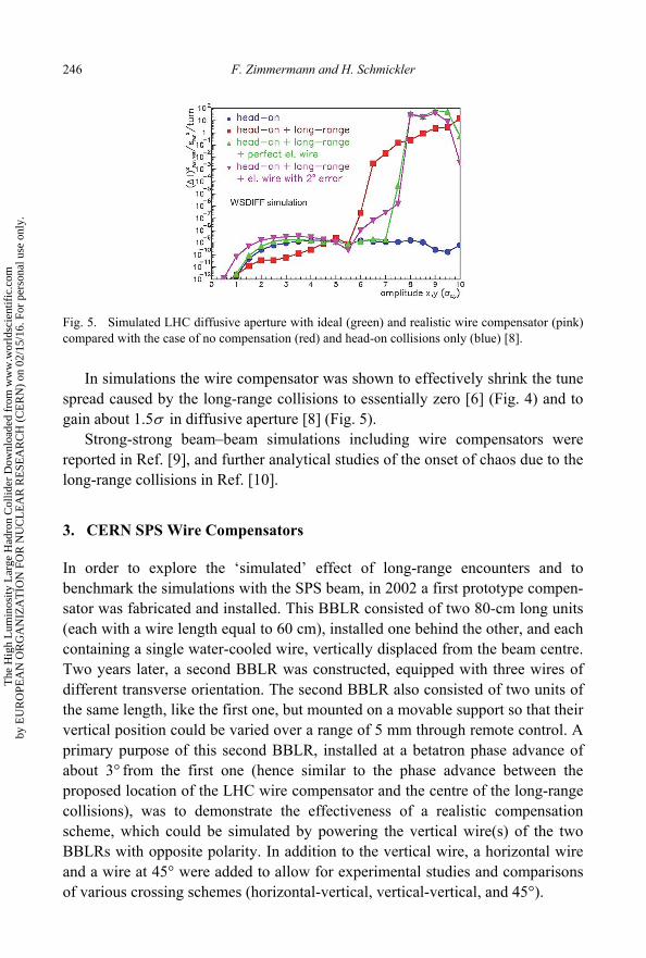
Fig. 5. Simulated LHC diffusive aperture with ideal (green) and realistic wire compensator (pink) compared with the case of no compensation (red) and head-on collisions only (blue) [8].
In simulations the wire compensator was shown to effectively shrink the tune spread caused by the long-range collisions to essentially zero [6] (Fig. 4) and to gain about 1.5 in diffusive aperture [8] (Fig. 5).
Strong-strong beam–beam simulations including wire compensators were reported in Ref. [9], and further analytical studies of the onset of chaos due to the long-range collisions in Ref. [10].
3. CERN SPS Wire Compensators
In order to explore the ‘simulated’ effect of long-range encounters and to benchmark the simulations with the SPS beam, in 2002 a first prototype compen-sator was fabricated and installed. This BBLR consisted of two 80-cm long units (each with a wire length equal to 60 cm), installed one behind the other, and each containing a single water-cooled wire, vertically displaced from the beam centre. Two years later, a second BBLR was constructed, equipped with three wires of different transverse orientation. The second BBLR also consisted of two units of the same length, like the first one, but mounted on a movable support so that their vertical position could be varied over a range of 5 mm through remote control. A primary purpose of this second BBLR, installed at a betatron phase advance of about 3°from the first one (hence similar to the phase advance between the proposed location of the LHC wire compensator and the centre of the long-range collisions), was to demonstrate the effectiveness of a realistic compensation scheme, which could be simulated by powering the vertical wire(s) of the two BBLRs with opposite polarity. In addition to the vertical wire, a horizontal wire and a wire at 45° were added to allow for experimental studies and comparisons of various crossing schemes (horizontal-vertical, vertical-vertical, and 45°).
The
Hig
h L
umin
osity
Lar
ge H
adro
n C
ollid
er D
ownl
oade
d fr
om w
ww
.wor
ldsc
ient
ific
.com
by E
UR
OPE
AN
OR
GA
NIZ
AT
ION
FO
R N
UC
LE
AR
RE
SEA
RC
H (
CE
RN
) on
02/
15/1
6. F
or p
erso
nal u
se o
nly.

Long-Range Beam–Beam Compensation Using Wires 247
Fig. 6. The first (left) and the second prototype wire compensator (right) installed in the CERN SPS in 2002 and 2004, respectively.
Fig. 7. Technical drawing of the second SPS wire compensator (2004).
Photographs of both devices are shown in Fig. 6, as well as a technical drawing in Fig. 7. The wire of the first BBLR is mounted at a fixed nominal vertical distance of 19 mm from the centre of the chamber (so that it is in the shadow of the SPS arc aperture). More details and documentation on the SPS wire compensator proto-types (and the experiments conducted in the SPS using these devices) can be found on a dedicated web site [11].
The needed wire current wI is related to the number of long range collisions #LR, the length of the wl and the bunch population bN via # /w b wI N ec LR l , where e denotes the elementary charge and c the speed of light. The two 60-cm long wires of one unit can be excited with up to 267 A of current, which, according to the above equation, produces an effect equivalent to 60 LHC LR collisions (e.g. roughly the combined effect of all nominal long-range encounters around IPs 1 and 5).
The
Hig
h L
umin
osity
Lar
ge H
adro
n C
ollid
er D
ownl
oade
d fr
om w
ww
.wor
ldsc
ient
ific
.com
by E
UR
OPE
AN
OR
GA
NIZ
AT
ION
FO
R N
UC
LE
AR
RE
SEA
RC
H (
CE
RN
) on
02/
15/1
6. F
or p
erso
nal u
se o
nly.

248 F. Zimmermann and H. Schmickler
Fig. 8. Side view of SPS BBLR no. 1.
Fig. 9. SPS BBLRs nos. 1 and 2 (two pairs of Plexiglas boxes) installed in SPS Straight Section 5.
Fig. 10. Horizontal and vertical beta functions across the two SPS BBLRs (each consisting of two units) [21].
The
Hig
h L
umin
osity
Lar
ge H
adro
n C
ollid
er D
ownl
oade
d fr
om w
ww
.wor
ldsc
ient
ific
.com
by E
UR
OPE
AN
OR
GA
NIZ
AT
ION
FO
R N
UC
LE
AR
RE
SEA
RC
H (
CE
RN
) on
02/
15/1
6. F
or p
erso
nal u
se o
nly.

Long-Range Beam–Beam Compensation Using Wires 249
Figure 8 presents a side view of the first BBLR device. Each BBLR, consisting of two units, has a total length of (2 0.8 ) m0.25 1.85 m. A photograph shows BBLRs 1 and 2 installed in the SPS tunnel (Fig. 9). Figure 10 illustrates the horizontal and vertical beta functions along the two two BBLR units. The average value of the beta functions is about 50 m.
Additional compensator wire units are available at CERN. A complete BBLR consisting of two units with water-cooling, similar to BBLR no. 2, is ready (repaired after an earlier leak). Two air-cooled BBLRs from the Relativistic Heavy Ion Collider (RHIC) have been shipped from Brookhaven National Laboratory and are in store at CERN [12]. Thus, including the two BBLRs presently installed in the SPS, a total of five sets are (or have been) available.
4. Scaling Laws
The perturbation by the wire compensator at a distance d from the beam center is
2,
( )p w wr l I
yec y d
with denoting the relativistic Lorentz factor, from which the relative perturbation at the dynamic aperture becomes
2,
( )p w w
y da
r ly I
ec n
where dan denotes the dynamic aperture in units of the rms beam size, wl the wire length and wI the wire current. This equation shows that, for constant normalized emittance, the effect in units of sigma is independent of energy and beta function. In scaled experiments the wire current is varied in direct proportion to the factor by which the emittance differs from the desired emittance.
5. History of SPS BBLR Studies
The SPS BBLRs were used to perform the following beam studies:
perturbation by single wire as LHC LR simulator (2002 to 2003) [13, 14]; two wire compensation, scaled experiments, distance scan (2004) [15, 16]; tests of crossing schemes (2004) [15, 16, 17]; one and two wires at different energies: 26, 37, and 55 GeV/c; scans of ,Q
distance, current (2007) [18, 19, 20];
The
Hig
h L
umin
osity
Lar
ge H
adro
n C
ollid
er D
ownl
oade
d fr
om w
ww
.wor
ldsc
ient
ific
.com
by E
UR
OPE
AN
OR
GA
NIZ
AT
ION
FO
R N
UC
LE
AR
RE
SEA
RC
H (
CE
RN
) on
02/
15/1
6. F
or p
erso
nal u
se o
nly.

250 F. Zimmermann and H. Schmickler
two-wire compensation with varying , ,wQ I Q scans at 55 GeV/c (2008) [21, 22];
two-wire compensation and excitation in coasts at 120 GeV/c (2009) [22]; and two-wire compensation and excitation in coasts at 55 GeV/c (2010) [23].
Figure 11 illustrates typical SPS cycles used towards the end of the last decade for BBLR studies at three different beam energies. During dedicated machine studies, at the target energy the SPS cycle could be stopped and the beam be made to ‘coast’ for, e.g. ten minutes for measurements of the beam lifetime in steady-state conditions and parameter scans.
Fig. 11. SPS cycles during experiments in 2008 and 2009 [21].
6. Technical Issues
A number of practical or technical issues had to be addressed, especially in the early days of the SPS BBLR studies. These included:
installation of dedicated ion chambers and photomultiplier tubes (PMTs) near the BBLR;
the addition of an inductive coil to suppress wire-current ripple; computation and experimental verification of wire heating; emittance blow-up by means of the transverse damper or by injection mismatch
together with resonance crossing (equalizing the vertical and horizontal emittances) so as to achieve the nominal LHC parameters or to increase sensitivity;
use of fast wire scanners and scrapers; installation of a dedicated dipole near the BBLR to correct the induced orbit
change locally; continuous tune corrections;
The
Hig
h L
umin
osity
Lar
ge H
adro
n C
ollid
er D
ownl
oade
d fr
om w
ww
.wor
ldsc
ient
ific
.com
by E
UR
OPE
AN
OR
GA
NIZ
AT
ION
FO
R N
UC
LE
AR
RE
SEA
RC
H (
CE
RN
) on
02/
15/1
6. F
or p
erso
nal u
se o
nly.

Long-Range Beam–Beam Compensation Using Wires 251
preparation and use of multiple superimposed orbit bumps to vary the beam-wire distance;
(later) choice of higher beam energy: 37, 55 or 120 GeV/c (for good lifetime without wire excitation); and
(later) experiments in coast (to avoid transient data).
Figure 12 illustrates the combination of orbit-corrector bumps used to vary the beam-wire distance at higher beam energy. The resulting minimum normalized distance in units of rms beam size depends on the beam energy and on the normalized emittance as shown in Fig. 13. In case the emittance was too small the beam could be blown up with transverse feedback and resonance crossing.
Fig. 12. Superimposed 3+5 corrector bumps at the SPS wire compensator [21].
Fig. 13. Minimum normalized distance in units of rms beam size as a function of normalized emittance for two beam energies [21]. The red line indicates a separation of 5 , which corresponds to the minimum separation considered for levelling at the HL-LHC [21].
The
Hig
h L
umin
osity
Lar
ge H
adro
n C
ollid
er D
ownl
oade
d fr
om w
ww
.wor
ldsc
ient
ific
.com
by E
UR
OPE
AN
OR
GA
NIZ
AT
ION
FO
R N
UC
LE
AR
RE
SEA
RC
H (
CE
RN
) on
02/
15/1
6. F
or p
erso
nal u
se o
nly.

252 F. Zimmermann and H. Schmickler
The natural SPS beam lifetime was about 30 h at 55 GeV/c, but only 5–10 min at 26 GeV/c (where the physical aperture was only about 4 ).
7. Single BBLR ‘Excitation’ Studies
Changes in orbit and tunes allow for a precise determination of the beam-wire distance. Example data from 2002 are shown in Figs. 14–16.
Fig. 14. Deflection angle at the wire compensator as a function of beam-wire distance, comparing data and measurements [14].
Fig. 15. Vertical tune change as a function of beam-wire distance, comparing data and measurements [14].
Fig. 16. Horizontal tune change as a function of beam-wire distance, comparing data and measure-ments [14].
The
Hig
h L
umin
osity
Lar
ge H
adro
n C
ollid
er D
ownl
oade
d fr
om w
ww
.wor
ldsc
ient
ific
.com
by E
UR
OPE
AN
OR
GA
NIZ
AT
ION
FO
R N
UC
LE
AR
RE
SEA
RC
H (
CE
RN
) on
02/
15/1
6. F
or p
erso
nal u
se o
nly.

Long-Range Beam–Beam Compensation Using Wires 253
The change in the beam orbit at the wire compensator, d , follows from the self-consistent equation
wire wire
tany p
y y
I l rd
ec d d Q Q
,
with d appearing on both sides, while the tune changes are given by
, wire wire
, 2
1
2p x y
x y
r I lQ
ec d d
.
In most of the later studies only the tune change was monitored. The effect of the BBLR wire on the nonlinear optics has also been studied, by
acquiring turn-by-turn beam-position monitor (BPM) data after kicking the beam. The nonlinearity of the wire field resulted in a reduced decoherence time, due to an increased tune shift with amplitude, and in (additional) spectral resonance lines. The measured tune shift was consistent with the theoretical predictions
wire wire 24
3ˆ
4p x
x
I l rQ y
ec d
and
wire wire 24
3ˆ
8p x
y
I l rQ y
ec d
,
where y denotes the peak vertical betatron oscillation amplitude of the beam after a kick.
The resonance lines introduced by the BBLR are illustrated in Fig. 17.
Fig. 17. Resonance spectra with wire excitation: experimental data with 240 A wire current at 9 (red) and 8 mm (green) beam-wire distance (left) and the corresponding simulation data (right) [18].
The
Hig
h L
umin
osity
Lar
ge H
adro
n C
ollid
er D
ownl
oade
d fr
om w
ww
.wor
ldsc
ient
ific
.com
by E
UR
OPE
AN
OR
GA
NIZ
AT
ION
FO
R N
UC
LE
AR
RE
SEA
RC
H (
CE
RN
) on
02/
15/1
6. F
or p
erso
nal u
se o
nly.

254 F. Zimmermann and H. Schmickler
A strong effect of chromaticity was noticed when the compensator was excited. Figure 18 shows the beam intensity evolution during ,x yQ scans at 37 GeV/c.
Figure 19 compares the measured (left) and simulated beam loss (right) for two different values of the vertical chromaticity as a function of the integrated wire strength.
Various attempts were made to directly measure the ‘diffusive’ or dynamic aperture. To this end, three types of signals were used: (1) lifetime and background, (2) beam profiles and final emittance, and (3) local diffusion rate inferred by scraper-retraction experiments. Figures 20 and 21 present example measurements of lifetime and background at 55 GeV/c. A drop in the lifetime and increased losses are observed for separations less than 9 ; at 7–8 separation the lifetime decreases to 1–5 h. These results indicated that the LHC nominal separation of 9.5 for the encounters between the IP and the first quadrupole Q1 is well chosen,
Fig. 18. Beam intensity as a function of time for various values of the horizontal ( , left)xQ or vertical chromaticity ( , right)yQ [20]. The wire excitation was 180 A-m, the beam momentum 37 GeV/c and the normalized beam-wire separation about 6.5 (9 mm).
Fig. 19. Relative beam loss for two different values of the vertical chromaticity as a function of wire excitation in units of A-m, comparing experimental data (left) and simulations (right) [20]. The beam-wire separation was ~ 6.6 .
The
Hig
h L
umin
osity
Lar
ge H
adro
n C
ollid
er D
ownl
oade
d fr
om w
ww
.wor
ldsc
ient
ific
.com
by E
UR
OPE
AN
OR
GA
NIZ
AT
ION
FO
R N
UC
LE
AR
RE
SEA
RC
H (
CE
RN
) on
02/
15/1
6. F
or p
erso
nal u
se o
nly.

Long-Range Beam–Beam Compensation Using Wires 255
Fig. 20. Lifetime as a function of the wire-beam separation in units of rms beam size with (green) and without (blue) wire excitation at 267 A, which corresponds to the nominal total number of LHC long-range encounters at IPs1 and 5. The red data were also taken with the wire excited, while in addition firing the (weak) tune kicker to add a further perturbation.
Fig. 21. Local relative beam loss rate measured by a photomultiplier as a function of the wire-beam separation in units of rms beam size with (green) and without (blue) a wire excitation of 267 A. As in Fig. 20 for the red data set the (weak) tune kicker was repeatedly fired while the wire was excited.
but ‘close to the edge’, assuming that the wire current of 267 A does indeed correspond to the long-range beam–beam effect in the LHC.
Beam profiles before and after wire excitation, measured with an SPS ‘wire scanner’ (fully unrelated to the wire compensator), reveal that the particles at large transverse amplitude are lost due to the wire excitation; see Fig. 22. These mea-surements confirmed that the wire compensator or the equivalent set of long-range encounters, acts as a highly effective diffusion enhancer and after some turns has an effect quite similar to the one of a physical scraper.
This type of measurement allows for an estimate of the diffusive/dynamic aperture. Specifically, an Abel transformation of the wire-scan data of the form [23, 24]
2 2
( )( ) 2
R
A
gA A d
A
The
Hig
h L
umin
osity
Lar
ge H
adro
n C
ollid
er D
ownl
oade
d fr
om w
ww
.wor
ldsc
ient
ific
.com
by E
UR
OPE
AN
OR
GA
NIZ
AT
ION
FO
R N
UC
LE
AR
RE
SEA
RC
H (
CE
RN
) on
02/
15/1
6. F
or p
erso
nal u
se o
nly.

256 F. Zimmermann and H. Schmickler
can be used to compute the change in the (normalized) amplitude distribution due to the wire excitation. For the data of Fig. 22 the results are presented in Fig. 23, indicating that in this particular example (with intentionally small separation) the dynamic aperture is at about 1 ).
Fig. 22. Beam profile from a wire scan before and after compensator-wire excitation measured at 26 GeV/c. The abscissa shows the wire-scan detector signal, the ordinate the (un-calibrated) wire-scanner position. The inferred initial and final emittances were 3.40 m and 1.15 m , respectively.
Fig. 23. Abel transformation of the beam-profile data from Fig. 22, revealing the change in the (normalized) amplitude distribution. The abscissa shows the normalized density or density difference, the ordinate the amplitude in units of the initial rms beam size .
Fig. 24. Final emittance without (red) and with wire excitation (blue 67 A, green 267 A) at a beam momentum of 26 GeV/c as a function of beam-compensator distance.
The
Hig
h L
umin
osity
Lar
ge H
adro
n C
ollid
er D
ownl
oade
d fr
om w
ww
.wor
ldsc
ient
ific
.com
by E
UR
OPE
AN
OR
GA
NIZ
AT
ION
FO
R N
UC
LE
AR
RE
SEA
RC
H (
CE
RN
) on
02/
15/1
6. F
or p
erso
nal u
se o
nly.

Long-Range Beam–Beam Compensation Using Wires 257
Figure 24 displays the final emittance inferred from the beam profiles as a function of beam-wire distance without wire excitation and for wire currents of 67 A and 267 A (the latter corresponding to 60 LHC long-range encounters). The reduction of the final emittance without wire excitation at smaller distances is due to mechanical scraping of the beam by the edge of the wire.
With the Abel-transformation technique it was not always possible to obtain a clean result for the diffusive aperture. Therefore, a different technique was also employed to infer the variation of the diffusive/dynamic aperture. Namely, without wire excitation, a known aperture restriction was introduced using a dedicated mechanical ‘scraper,’ and wire scans were then executed to determine the ‘final emittance’ corresponding to a given known aperture determined by the scraper position. This calibration measurement is presented in Fig. 25 — the curve of measured final emittance as a function of scraper position allows estimation of the effective aperture due to the wire excitation from the associated ‘final emittance’ value.
Following this plan and using the calibration line of Fig. 25, measurement results for different wire currents were converted into normalized diffusive apertures. The result, shown in Fig. 26, suggests a linear dependence of the
Fig. 25. Calibration of the final emittance values by a mechanical scraper.
Fig. 26. Effect of wire current on SPS dynamic aperture (26 GeV/c), inferred from final emittance and the calibration of Fig. 26.
The
Hig
h L
umin
osity
Lar
ge H
adro
n C
ollid
er D
ownl
oade
d fr
om w
ww
.wor
ldsc
ient
ific
.com
by E
UR
OPE
AN
OR
GA
NIZ
AT
ION
FO
R N
UC
LE
AR
RE
SEA
RC
H (
CE
RN
) on
02/
15/1
6. F
or p
erso
nal u
se o
nly.

258 F. Zimmermann and H. Schmickler
dynamic aperture on the square root of the wire current, which is consistent with a scaling law first pointed out by Irwin [4]. In the figure, the measured dynamic aperture is smaller than the simulated diffusive aperture, especially at lower current, hinting at additional effects not included in the simulations or at a systematic error in the calibration method.
Yet another approach to measuring the diffusive aperture is to directly detect the diffusion rates at various transverse amplitudes, by inserting a scraper to remove particles in a small area around the target amplitude article, then retracting this scraper by a small step, and observing how the loss signal reappears as particles diffuse outwards to the new position of the scraper. This type of measurement was previously used at HERA (and elsewhere) to determine the local diffusion coefficients [25]. Unfortunately, scraper retraction attempts for the SPS wire-compensator studies were not very successful.
One of the most interesting results from the SPS wire measurements is the measured dependence of the ‘beam lifetime’ beam , as inferred from the beam loss during a cycle at 26 GeV/c, on the beam-wire distance d [15], illustrated in Fig. 27. The measured dependence extremely well follows a 5th order power law as seen from the fitting result embedded in the figure (another fit, with an exponential law, is shown as well). It has been suggested [26] that a nearby low-order resonance of order n should cause a dependence 1
beam ~ 1/ nd and that the power in the exponent should, therefore, depend on the betatron tunes. Indeed at the Tevatron (with an electron lens applied as ‘wire’) [27] and at RHIC [28], operating at other working points in the tune diagram, different power laws were observed (third power and linear dependence, respectively). Figure 28, presenting SPS data for three different sets of tunes, taken several years later at a higher energy, confirms that the losses due to the wire are strongly tune dependent.
Fig. 27. Beam lifetime as a function of beam-wire distance at 26 GeV/c, for betatron tunes of xQ 0.321 and 0.291yQ [14].
The
Hig
h L
umin
osity
Lar
ge H
adro
n C
ollid
er D
ownl
oade
d fr
om w
ww
.wor
ldsc
ient
ific
.com
by E
UR
OPE
AN
OR
GA
NIZ
AT
ION
FO
R N
UC
LE
AR
RE
SEA
RC
H (
CE
RN
) on
02/
15/1
6. F
or p
erso
nal u
se o
nly.

Long-Range Beam–Beam Compensation Using Wires 259
Fig. 28. Beam losses as a function of beam-wire distance for three different pairs of tunes at 37 GeV/c with 1.1 s cycle [21].
Fig. 29. Beam losses as a function of wire current at 37 GeV/c with a 1.1 s cycle, for betatron tunes of 0.31xQ and 0.32yQ (nominal values for LHC collisions) [21].
Extrapolating the measurement of Fig. 27 to the nominal LHC beam–beam distance, ~ 9.5 predicts a 6 min lifetime. This result was one of the motivations for raising the SPS beam energy and for performing measurements with coasting (non-cycling machine) beams in later studies, where the beam lifetimes were significantly higher.
Figure 29 shows beam losses as a function of wire current wI for different normalized beam-wire separations nd (in units of ). These later results were fitted as [21]:
2beam loss (%) 0.07 ndwe I .
The
Hig
h L
umin
osity
Lar
ge H
adro
n C
ollid
er D
ownl
oade
d fr
om w
ww
.wor
ldsc
ient
ific
.com
by E
UR
OPE
AN
OR
GA
NIZ
AT
ION
FO
R N
UC
LE
AR
RE
SEA
RC
H (
CE
RN
) on
02/
15/1
6. F
or p
erso
nal u
se o
nly.

260 F. Zimmermann and H. Schmickler
8. Studies for Wire Compensators in the LHC
For a successful compensation of long range beam–beam effects the location of the compensator must fulfil the following requirements:
No phase advance to the origin of the effect (or a phase advance equal to a multiple of ); ideally the wire should be located in the drift space before the final-focus quadrupoles, i.e. the longitudinal space where the parasitic long range encounters occur, which is not possible (exactly due to the presence of the second beam).
A region where the values of the horizontal and vertical beta functions are equal.
In order to get the compensation correct for all multipoles the transverse location of a wire compensator must be on the inside of the compensated beam, i.e. between the two circulating beams. This poses a significant constraint, since in the ideal longitudinal position the transverse separation of the beams is only a few centimeters. [The strength the nth multipole scales as / ,n
wI d i.e. linearly with the wire current ,wI and with the nth power of the inverse separation d, including the sign of the separation. Hence, placing the wire compensator on the outside with opposite current would not be a solution — this would double the magnitude of every second multipole field excited by the long-range collisions, instead of cancelling it.]
In a thesis [29] the compensation scheme for the LHC was studied in detail using simulations with the BBTRACK code. Figure 30 shows the layout of an LHC high luminosity insertion (top) and the related beta functions for the nominal optics
Fig. 30. Schematic layout of a LHC high luminosity insertion (top) and the related beta functions for the nominal optics and another proposed modified optics [29].
The
Hig
h L
umin
osity
Lar
ge H
adro
n C
ollid
er D
ownl
oade
d fr
om w
ww
.wor
ldsc
ient
ific
.com
by E
UR
OPE
AN
OR
GA
NIZ
AT
ION
FO
R N
UC
LE
AR
RE
SEA
RC
H (
CE
RN
) on
02/
15/1
6. F
or p
erso
nal u
se o
nly.

Long-Range Beam–Beam Compensation Using Wires 261
and another proposed modified optics. The ideal position for a wire compensator is indicated as “W-BBC”. In this location a final compensation scheme would be implemented. Since the compensation will be local, one compensator for each beam and in each high luminosity IP will be needed, hence a total of four compensators.
Furthermore, Fig. 30 indicates another location (W-TCT), the location of the TCT collimators. In the planned upgrade of the LHC collimation system at these locations new collimators will be installed in the time frame between LS1 and LS2 (2015–2018). In order to validate the concept of the BBLRs a demonstrator project is planned, for which wires will be integrated into collimator jaws. Therefore the positions of the collimators have also been included in the simulations.
9. Simulation Results
As indicators for the effectiveness of the compensation results two independent methods were used in [29]:
(a) the stability analysis of particle trajectories over many terms expressed by the value of the Lyapunov exponent [30]; and
(b) the tune footprint of particles in the lattice resonance diagram.
Typical examples of these studies are shown in Figs. 31 and 32. As main results we can report the following [29]:
Considering a 1 m long wire at the TCT location, the best compensation of the BBLR effect can be obtained with a DC wire current of 177 A, per IP, at a distance of 9.5 to the beam. By geometrical scaling a current of 237 A is needed at a
Fig. 31. Two dimensional stability diagram for simulated collisions in the LHC (left) and for collisions with additional BBLR compensation (right). Unstable particles are identified by red dots in the figures [29]. The colour indicates the number of turns after which a trajectory is diagnosed as unstable through the irregular, exponential evolution of the phase-space distance between two twin particles. Points without colour are considered to be stable.
The
Hig
h L
umin
osity
Lar
ge H
adro
n C
ollid
er D
ownl
oade
d fr
om w
ww
.wor
ldsc
ient
ific
.com
by E
UR
OPE
AN
OR
GA
NIZ
AT
ION
FO
R N
UC
LE
AR
RE
SEA
RC
H (
CE
RN
) on
02/
15/1
6. F
or p
erso
nal u
se o
nly.

262 F. Zimmermann and H. Schmickler
Fig. 32. Two dimensional tune diagram for simulated collisions in the LHC (left) and for collisions with additional BBLR compensation (right). The BBLR compensation changes the tune of the particles, which are affected by the long range beam force, back to the tune of the unperturbed beam [29].
distance of 11 . These wire current values correspond to a symmetric layout with one compensator left of the IP and another — for the second IP — on the right side. This setup will be necessary in the TCT locations, since the ratio of the hori-zontal and vertical beta functions is not equal to one (see Fig. 30). [The LHC currents computed here are lower than the 267 A quoted above for the SPS exper-iments, performed with a 1.2 m long wire, since the latter represented the accumu-lated nominal LHC long-range beam–beam effect from two IPs.]
The LHC wire compensators at the TCT location should allow reducing the crossing angle from 12 without wire to 9.5 with wire, or from 9.5 without wire to 8 with wire, at comparable stability in phase space (and, consequently, at similar beam lifetimes) [29].
10. Demonstrator Setup
Due to machine-protection considerations, the integration of DC powered wires into collimator jaws seems to be the only possibility to enable some beam tests before embarking on a final implementation of the wires for the LHC high luminosity operation. This integration requires the solution of several important technical issues:
No interference of the wires with the nominal operation of the collimators; Transfer of 1 kW resistive heat loss in the wire by heat conduction to the water
cooled collimator jaw; Shielding of the wire inside the collimator through a thin metallic layer towards
the beam for impedance reasons.
The
Hig
h L
umin
osity
Lar
ge H
adro
n C
ollid
er D
ownl
oade
d fr
om w
ww
.wor
ldsc
ient
ific
.com
by E
UR
OPE
AN
OR
GA
NIZ
AT
ION
FO
R N
UC
LE
AR
RE
SEA
RC
H (
CE
RN
) on
02/
15/1
6. F
or p
erso
nal u
se o
nly.

Long-Range Beam–Beam Compensation Using Wires 263
Figure 33 sketches the implementation principle, where the 1 mm thick wire is shown inside a small tungsten block, which is embedded in the collimator jaw [31]. Figures 34 and 35 present further integration details of the complex mechanical engineering aspects of the wire integration.
At the earliest the wire equipped collimators will be installed in the LHC in the winter shutdown 2015/2016.
After the installation machine experiments are planned, which aim to validate the coherence of predictions by simulation with machine experiments. Beam transfer functions, transverse particle distributions and bunch lifetimes will be used as observables. This setup will be the first time, at CERN, that one attempts to observe a compensation of the long-range beam–beam effects by observing an improvement of critical beam operation parameters (e.g. lifetime and losses). All past experiments in the SPS “only” demonstrated that a wire can deteriorate beam operation parameters and that two neighbouring wires can compensate each other.
Fig. 33. Schematic layout of a wire integrated into a collimator jaw [31].
Fig. 34. Technical drawing of the wire (right side) in the collimator jaw [31].
20 mmclearance
y
x
W
Cu
The
Hig
h L
umin
osity
Lar
ge H
adro
n C
ollid
er D
ownl
oade
d fr
om w
ww
.wor
ldsc
ient
ific
.com
by E
UR
OPE
AN
OR
GA
NIZ
AT
ION
FO
R N
UC
LE
AR
RE
SEA
RC
H (
CE
RN
) on
02/
15/1
6. F
or p
erso
nal u
se o
nly.

264 F. Zimmermann and H. Schmickler
Fig. 35. Technical detail of the integration: Outside the space in which the wire is cooled by heat conduction, the wire diameter had to be increased in order to avoid the burning of the wire at nominal current (arrow) [31].
Some previous attempts to compensate long-range beam–beam effects with a wire have been made at RHIC [32] (considering a single long-range collision) and at DAFNE [33] (with lepton beams, and successfully used in actual operation).
11. Conclusions and Outlook
From the SPS (and similar plus even two-beam experiments in RHIC) we have first indications of BBLRs affecting the particle beams in the predicted way.
Simulations show a potential gain of using these wires for gaining dynamic aperture, hence giving the possibility to reduce the crossing angles, and therefore producing higher luminosity with the same beams.
For future wire BBLRs in the high luminosity period of the LHC, 8 m long sections are reserved at a distance of about 100 m from each IP1 and IP5. In terms of beam dynamics these locations would be ideal for BBLRs, whereas the high flux of secondary neutrons will pose severe constraints for any technical realization. In order to be able to place (and align) a “wire” in these locations, in particular in between the two counter-rotating proton beams only an electron beam similar to well established electron coolers is envisaged at the present moment. Machine Protection considerations would be another argument for using electron beams as wires, since these would be non-destructible devices that can be placed at amplitudes smaller than that of the tertiary and secondary collimators.
An implementation sketch is shown in Fig. 36. Obviously the usage of an electron beam would allow a pulsed operation and hence even individual compen-sation of each proton bunch.
The
Hig
h L
umin
osity
Lar
ge H
adro
n C
ollid
er D
ownl
oade
d fr
om w
ww
.wor
ldsc
ient
ific
.com
by E
UR
OPE
AN
OR
GA
NIZ
AT
ION
FO
R N
UC
LE
AR
RE
SEA
RC
H (
CE
RN
) on
02/
15/1
6. F
or p
erso
nal u
se o
nly.

Long-Range Beam–Beam Compensation Using Wires 265
Fig. 36. Sketch of an electron cooler type layout for a non-destructible wire BBLR [31].
On the other hand such an implementation is beyond what has been achieved so far: Assuming an effective length of 6 m on both sides of the IP an electron beam current of about 30 A would be needed in order to produce the field equivalent to a 1 m long wire powered at 177 A. This is about an order of magnitude larger than what has been achieved for the Tevatron Electron Lens [27, 34] and with the electron lenses at RHIC [35]. A factor of 2 could be gained by placing a second electron beam wire on the other side of the IP, resulting in a total of eight installations.
Acknowledgments
The reported SPS wire experiments would not have been possible without the ideas, help and important contributions of Gerard Burtin, Rama Calaga, Jackie Camas, Gijs de Rijk, Octavio Dominguez, Ulrich Dorda, Jean-Pierre Koutchouk, Elias Métral, Yannis Papaphilippou, Federico Roncarolo, Tanaji Sen, Vladimir Shiltsev, Guido Sterbini, Rogelio Tomas, and Jörg Wenninger.
For the proposed BBLR in the LHC the contributions of Tatiana Rijoff, Ralph Steinhagen, Stephane Fartoukh, Tatiana Pieloni, Stefano Redaelli, Alessandro Bertarelli, Guillaume Maitrejean, Luca Gentini, Gianluigi Arduini and Yannis Papaphilippou are warmly acknowledged.
References
[1] D. Neuffer and S. Peggs, Beam-Beam Tune Shifts and Spreads in the SSC: Head-On, Long Range and PACMAN conditions, SSC-63 (1986).
[2] W. Herr, Tune Shifts and Spreads due to the Long-Range Beam-Beam Effects in the LHC, CERN/SL/90-06 (AP) (1990).
[3] W. Chou and D. M. Ritson, Dynamic aperture studies during collisions in the LHC, CERN LHC Project Report 123 (1998).
The
Hig
h L
umin
osity
Lar
ge H
adro
n C
ollid
er D
ownl
oade
d fr
om w
ww
.wor
ldsc
ient
ific
.com
by E
UR
OPE
AN
OR
GA
NIZ
AT
ION
FO
R N
UC
LE
AR
RE
SEA
RC
H (
CE
RN
) on
02/
15/1
6. F
or p
erso
nal u
se o
nly.

266 F. Zimmermann and H. Schmickler
[4] J. Irwin, Diffusive Losses from SSC Particle Bunches due to Long Range Beam-beam Interactions, SSC-223 (1989).
[5] Y. Papaphilippou and F. Zimmermann, Weak-strong beam-beam simulations for the Large Hadron Collider, Phys. Rev. ST Accel. Beams 2, 104001 (1999).
[6] J.-P. Koutchouk, Principle of a Correction of the Long-Range Beam-Beam Effect in LHC using Electromagnetic Lenses, LHC Project Note 223 (2000).
[7] J.-P. Koutchouk, Correction of the Long-Range Beam-Beam Effect in LHC using Electromagnetic Lenses, SL Report 2001-048 (2001).
[8] F. Zimmermann, Weak-Strong Simulation Studies for the LHC Long-Range Beam-Beam Compensation, Beam-Beam Workshop 2001 FNAL; LHC Project Report 502 (2001).
[9] J. Lin, J. Shi and W. Herr, Study of the Wire Compensation of Long-Range Beam-Beam Interactions in LHC with a Strong-Strong Beam-Beam Simulation, EPAC 2002, Paris (2002).
[10] Y. Papaphilippou and F. Zimmermann, Estimates of diffusion due to long-range beam-beam collisions, Phys. Rev. ST Accel. Beams 5, 074001 (2002).
[11] CERN Beam-Beam Compensation web site at http://cern-ab-bblr.web.cern.ch/cern-ab-bblr.
[12] The RHIC wires were kindly provided by M. Minty and T. Curcio. [13] J.-P. Koutchouk, J. Wenninger and F. Zimmermann, Compensating Parasitic
Collisions using Electromagnetic Lenses, presented at ICFA Beam Dynamics Workshop on High-Luminosity e+e- Factories (‘Factories'03’) SLAC; in CERN-AB-2004-011-ABP (2004).
[14] J.-P. Koutchouk, J. Wenninger and F. Zimmermann, Experiments on LHC Long-Range Beam-Beam Compensation in the SPS, EPAC'04 Lucerne (2004).
[15] F. Zimmermann, J.-P. Koutchouk, F. Roncarolo, J. Wenninger, T. Sen, V. Shiltsev and Y. Papaphilippou, Experiments on LHC Long-Range Beam-Beam Compensation and Crossing Schemes at the CERN SPS in 2004, PAC'05 Knoxville (2005).
[16] F. Zimmermann, Beam-Beam Compensation Schemes, in Proc. First CARE-HHH-APD Workshop (HHH-2004), CERN, Geneva, Switzerland, CERN-2005-006, p. 101 (2005).
[17] F. Zimmermann and U. Dorda, Progress of Beam-Beam Compensation Schemes, in Proc. 2nd CARE-HHH-APD Workshop on Scenarios for the LHC Luminosity Upgrade, Arcidosso, Italy, 2005, CERN-2006-008 (2005).
[18] U. Dorda, J-P. Koutchouk, R. Tomas, J. Wenninger, F. Zimmermann, R. Calaga and W. Fischer, Wire Excitation Experiments in the CERN SPS, in Proc. EPAC08, Genoa (2008).
[19] U. Dorda and F. Zimmermann, Wire Compensation: Performance, SPS MDs, Pulsed System, in Proc. IR07, p. 98, CERN-2008-006 (2007).
[20] U. Dorda, Compensation of long-range beam-beam interaction at the CERN LHC, PhD Thesis, Vienna TU., CERN-THESIS-2008-055 (2008).
[21] G. Sterbini, An Early Separation Scheme for the LHC Luminosity Upgrade, PhD Thesis EPFL, CERN-THESIS-2009-136 (2009).
[22] G. Sterbini, R. Calaga et al., unpublished; see CERN BBLR web site in Ref. [11].
The
Hig
h L
umin
osity
Lar
ge H
adro
n C
ollid
er D
ownl
oade
d fr
om w
ww
.wor
ldsc
ient
ific
.com
by E
UR
OPE
AN
OR
GA
NIZ
AT
ION
FO
R N
UC
LE
AR
RE
SEA
RC
H (
CE
RN
) on
02/
15/1
6. F
or p
erso
nal u
se o
nly.

Long-Range Beam–Beam Compensation Using Wires 267
[23] P. W. Krempl, The Abel-type Integral Transformation with the Kernel (t2-x2)-1/2 and its Application to Density Distributions of Particle Beams, CERN Note MPS/Int. BR/74-1 (1974).
[24] C. Carli, A. Jansson, M. Lindroos and H. Schönauer, A Comparative Study of Profile and Scraping Methods for Emittance Measurements in the PS Booster, Particle Accelerators 63, 255–277 (2000).
[25] M. Seidel, The Proton Collimation System of HERA, PhD Thesis, U. Hamburg, DESY-94-103 (1994).
[26] V. Shiltsev, private communication, 28 November 2004. [27] F. Zimmermann, P. Lebrun, T. Sen, V. Shiltsev and X. L. Zhang, Using the Tevatron
Electron Lens as a Wire and Other TEL Studies at FNAL, CERN AB-Note-2004-041 (2004).
[28] W. Fischer, R. Calaga, U. Dorda, J.-P. Koutchouk, F. Zimmermann, V. Ranjbar, T. Sen, J. Shi, J. Qiang and A. Kabel, Observation of Long-Range Beam-Beam Effect in RHIC and Plans for Compensation, EPAC’06, Edinburgh (2006).
[29] T. Rijoff, Testing long range beam-beam compensation for the LHC luminosity upgrade, master thesis, Milan U., CERN-THESIS-2012-377 (2012).
[30] F. Schmidt, F. Willeke and F. Zimmermann, Comparison of methods to determine long-term stability in proton storage rings, Part. Accel. 35, 249 (1991).
[31] R. Steinhagen, LHC Beam-Beam Compensator – Status Update, 3rd Joint HiLumi LHC LARP Annual Meeting, Daresbury Laboratory (2013).
[32] W. Fischer et al., Long-range and head-on beam-beam compensation studies in RHIC with lessons for the LHC, in Proc. Final CARE-HHH Workshop on Scenarios for the LHC Upgrade and FAIR, Chavannes-de-Bogis, Switzerland, 24–25 Nov. 2008, CERN Yellow Report CERN-2009-004, pp. 92–101 (2009).
[33] C. Milardi, D. Alesini, M. A. Preger, P. Raimondi, M. Zobov and D. Shatilov, DAFNE Lifetime Optimization with Octupoles and Compensating Wires, in Proc. CARE-HHH-APD Workshop on Interaction Regions for the LHC Upgrade, DAFNE, and SuperB, Frascati, Italy, 6–9 Nov. 2007, CERN Yellow Report CERN-2008-006, pp. 92–97 (2008).
[34] V. Shiltsev, Y. Alexahin, K. Bishofberger, V. Kamerdzhiev, V. Parkhomchuk, V. Reva, N. Solyak, D. Wildman, X.-L. Zhang and F. Zimmermann, Experimental Studies of Compensation of Beam-Beam Effects with Tevatron Electron Lenses, New J. Phys. 10, 043042 (2008).
[35] W. Fischer et al., First Experience with Electron Lenses for Beam-Beam Compensation in RHIC, in Proc. IPAC14, Dresden (2014).
The
Hig
h L
umin
osity
Lar
ge H
adro
n C
ollid
er D
ownl
oade
d fr
om w
ww
.wor
ldsc
ient
ific
.com
by E
UR
OPE
AN
OR
GA
NIZ
AT
ION
FO
R N
UC
LE
AR
RE
SEA
RC
H (
CE
RN
) on
02/
15/1
6. F
or p
erso
nal u
se o
nly.