Localization Technology - Department of Computer … · Outline •Defining location •Methods for...
94
Localization Technology
Transcript of Localization Technology - Department of Computer … · Outline •Defining location •Methods for...
Localization Technology
Outline
• Defining location
• Methods for determining location
• Triangulation, trilateration, RSSI, etc.
• Location Systems
Introduction
We are here !
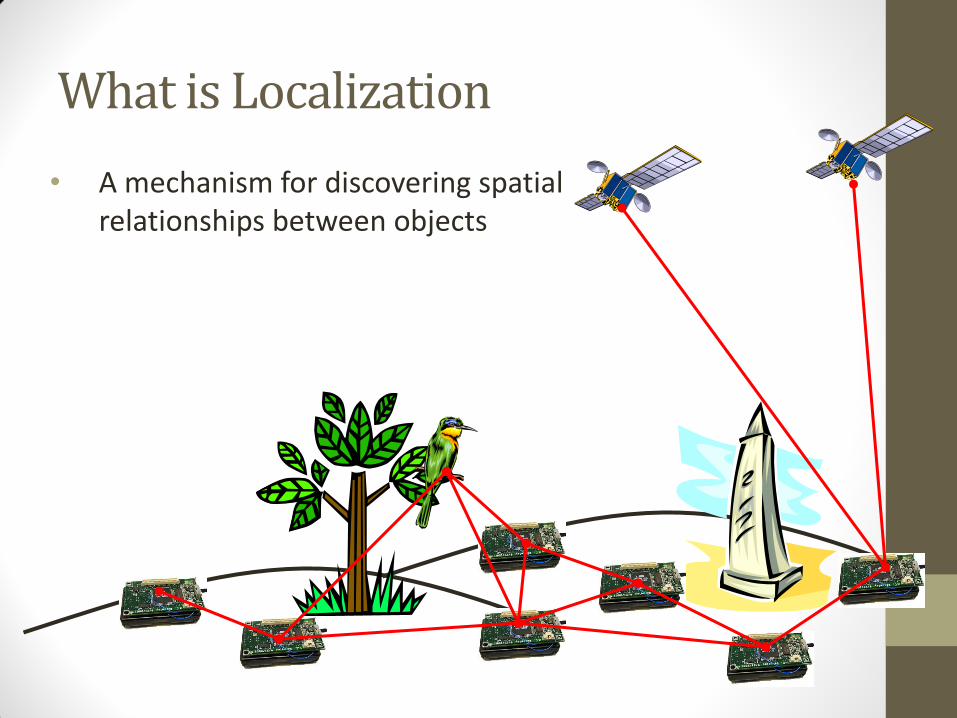
What is Localization
• A mechanism for discovering spatial relationships between objects
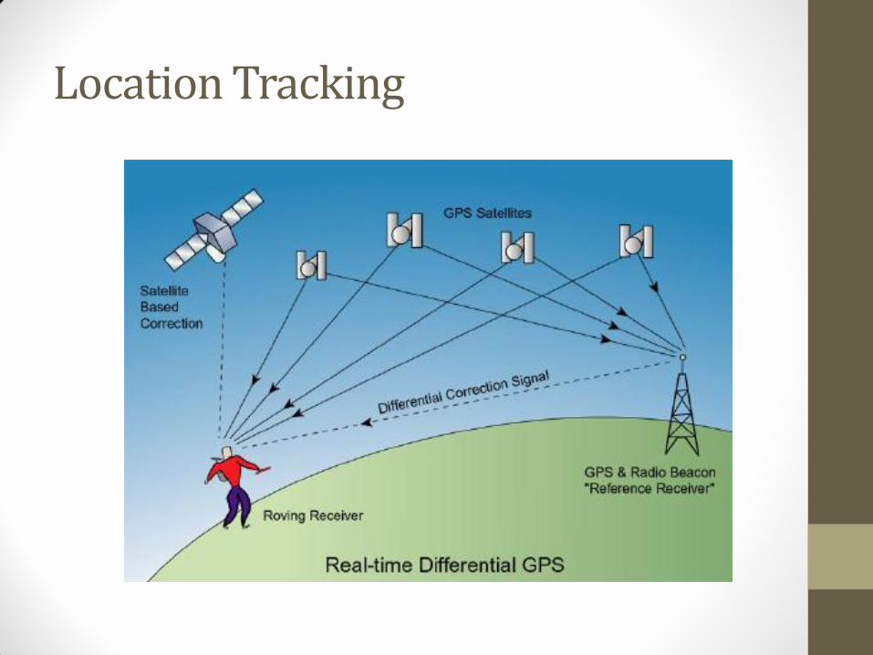
Location Tracking
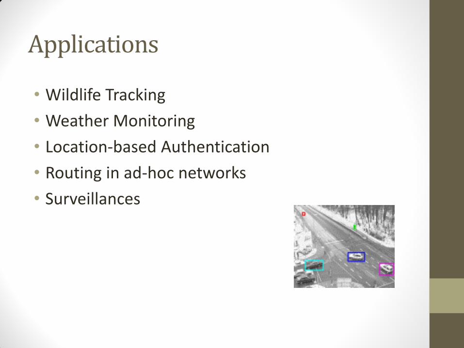
Applications
• Wildlife Tracking
• Weather Monitoring
• Location-based Authentication
• Routing in ad-hoc networks
• Surveillances
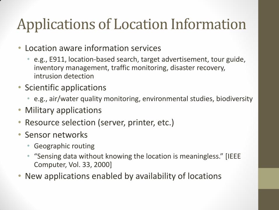
Applications of Location Information
• Location aware information services • e.g., E911, location-based search, target advertisement, tour guide,
inventory management, traffic monitoring, disaster recovery, intrusion detection
• Scientific applications • e.g., air/water quality monitoring, environmental studies, biodiversity
• Military applications
• Resource selection (server, printer, etc.)
• Sensor networks • Geographic routing
• “Sensing data without knowing the location is meaningless.” [IEEE Computer, Vol. 33, 2000]
• New applications enabled by availability of locations
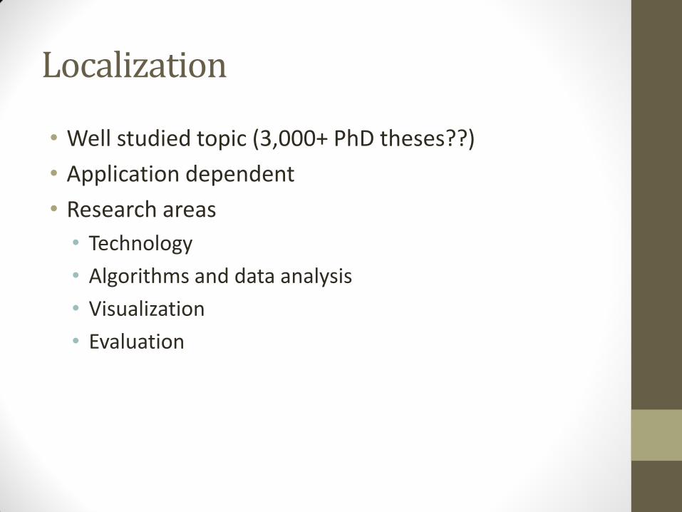
Localization
• Well studied topic (3,000+ PhD theses??)
• Application dependent
• Research areas
• Technology
• Algorithms and data analysis
• Visualization
• Evaluation
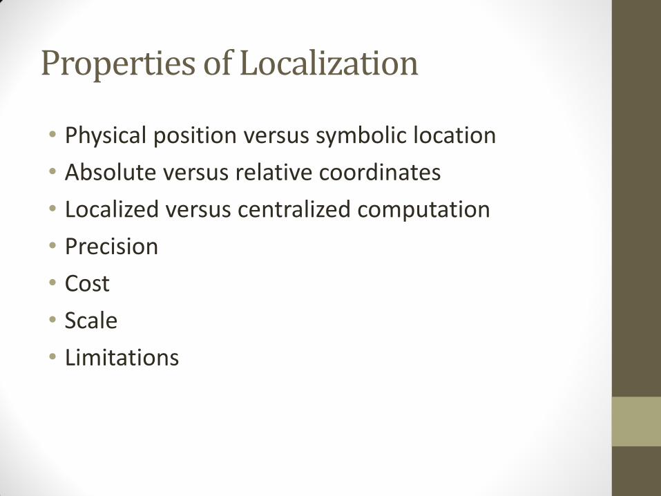
Properties of Localization
• Physical position versus symbolic location
• Absolute versus relative coordinates
• Localized versus centralized computation
• Precision
• Cost
• Scale
• Limitations
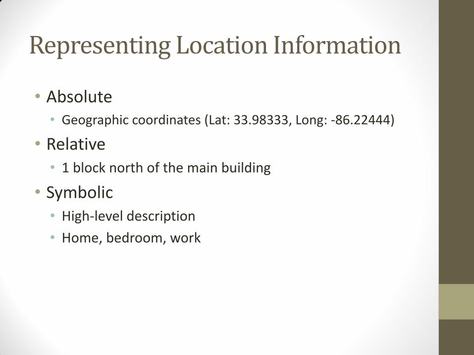
Representing Location Information
• Absolute • Geographic coordinates (Lat: 33.98333, Long: -86.22444)
• Relative • 1 block north of the main building
• Symbolic • High-level description
• Home, bedroom, work
No One Size Fits All!
• Accurate
• Low-cost
• Easy-to-deploy
• Ubiquitous
• Application needs determine technology
Consider for Example…
• Motion capture
• Car navigation system
• Finding a lost object
• Weather information
• Printing a document
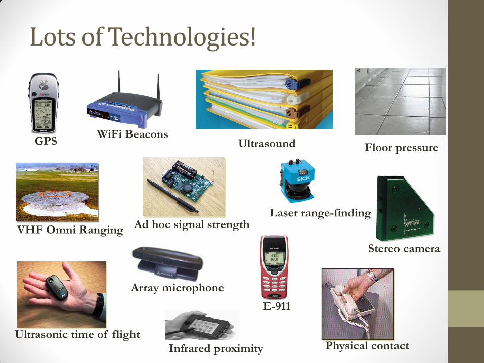
Lots of Technologies!
Ultrasonic time of flight
E-911
Stereo camera
Ad hoc signal strength
GPS
Physical contact
WiFi Beacons
Infrared proximity
Laser range-finding
VHF Omni Ranging
Array microphone
Floor pressure Ultrasound
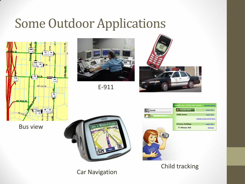
Some Outdoor Applications
Car Navigation Child tracking
Bus view
E-911
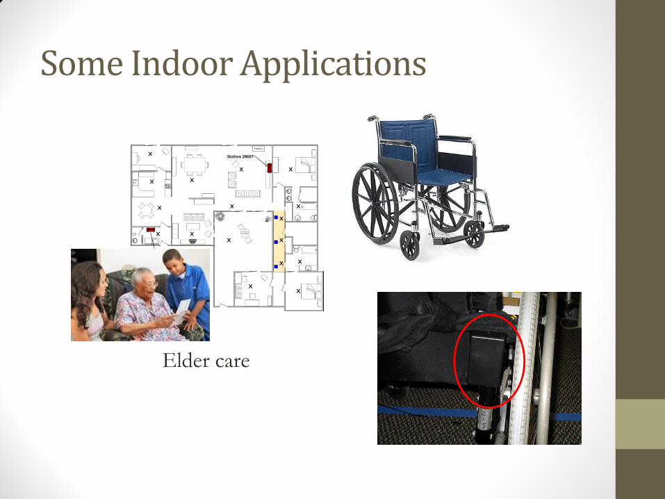
Some Indoor Applications
Elder care
Outline
• Defining location
• Methods for determining location
• Triangulation, trilateration, RSSI, etc.
• Location Systems
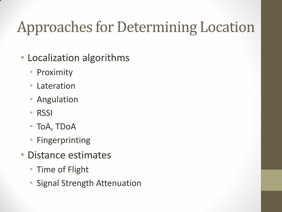
Approaches for Determining Location
• Localization algorithms
• Proximity
• Lateration
• Angulation
• RSSI
• ToA, TDoA
• Fingerprinting
• Distance estimates
• Time of Flight
• Signal Strength Attenuation
Proximity
• Simplest positioning technique
• Closeness to a reference point
• It can be used to decide whether a node is in the proximity of an anchor
• Based on loudness, physical contact, etc.
• Can be used for positioning when several overlapping anchors are available
• Centronoid localization
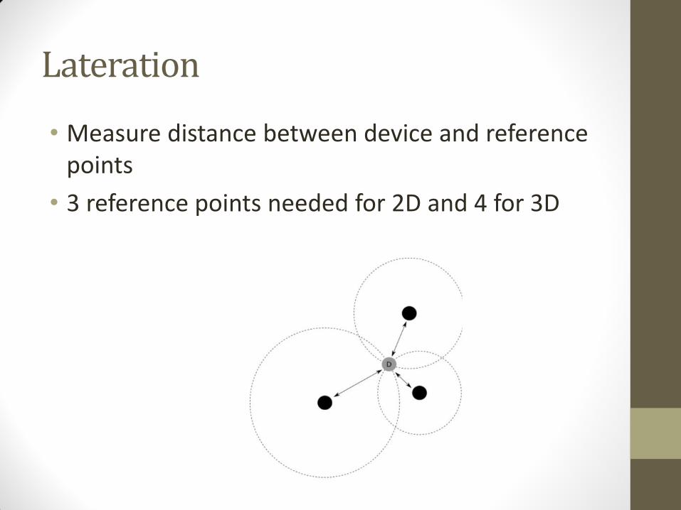
Lateration
• Measure distance between device and reference points
• 3 reference points needed for 2D and 4 for 3D
Lateration vs. Angulation
• When distances between entities are used, the approach is called lateration
• when angles between nodes are used, one talks about angulation
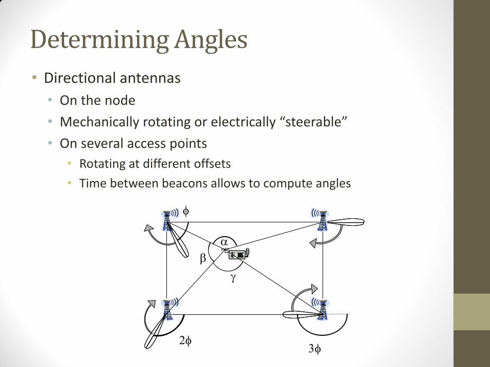
Determining Angles
• Directional antennas
• On the node
• Mechanically rotating or electrically “steerable”
• On several access points
• Rotating at different offsets
• Time between beacons allows to compute angles
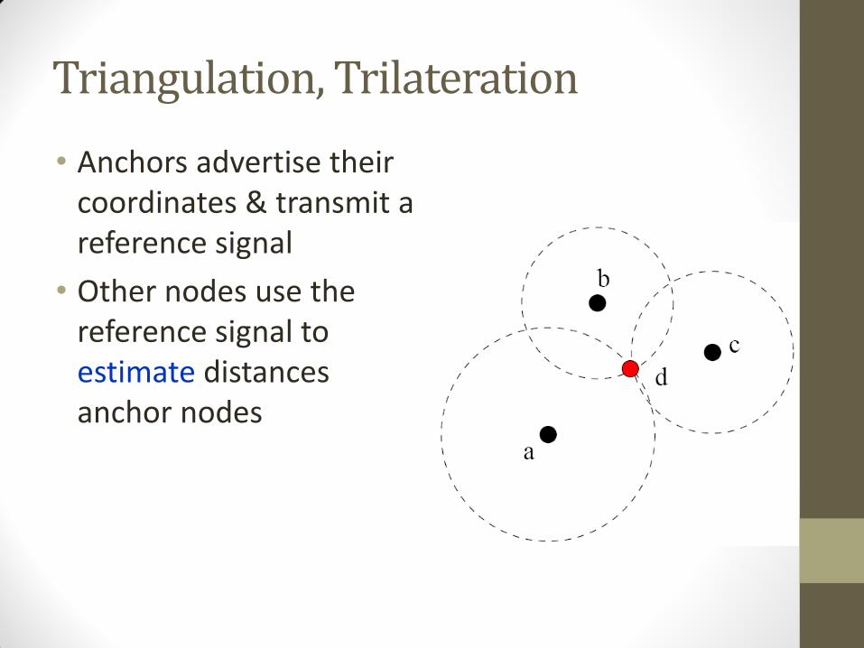
Triangulation, Trilateration
• Anchors advertise their coordinates & transmit a reference signal
• Other nodes use the reference signal to estimate distances anchor nodes
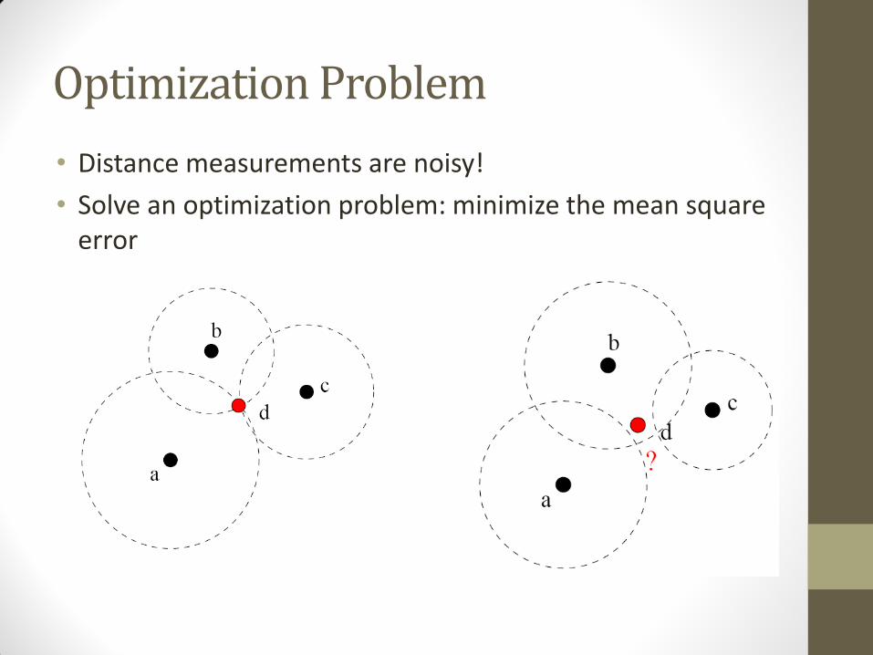
Optimization Problem
• Distance measurements are noisy!
• Solve an optimization problem: minimize the mean square error
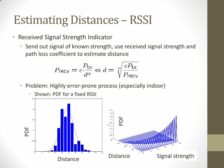
Estimating Distances – RSSI • Received Signal Strength Indicator
• Send out signal of known strength, use received signal strength and path loss coefficient to estimate distance
• Problem: Highly error-prone process (especially indoor)
• Shown: PDF for a fixed RSSI
Distance Distance Signal strength
PD
F
PD
F
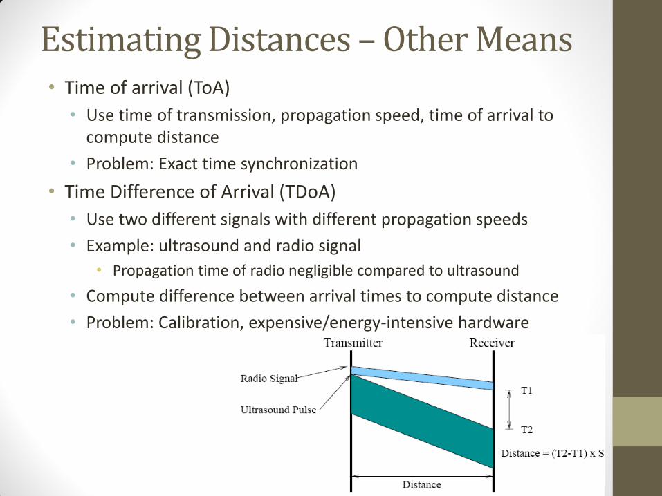
Estimating Distances – Other Means • Time of arrival (ToA)
• Use time of transmission, propagation speed, time of arrival to compute distance
• Problem: Exact time synchronization
• Time Difference of Arrival (TDoA)
• Use two different signals with different propagation speeds
• Example: ultrasound and radio signal
• Propagation time of radio negligible compared to ultrasound
• Compute difference between arrival times to compute distance
• Problem: Calibration, expensive/energy-intensive hardware
Fingerprinting
• Mapping solution
• Address problems with multipath
• Better than modeling complex RF propagation pattern
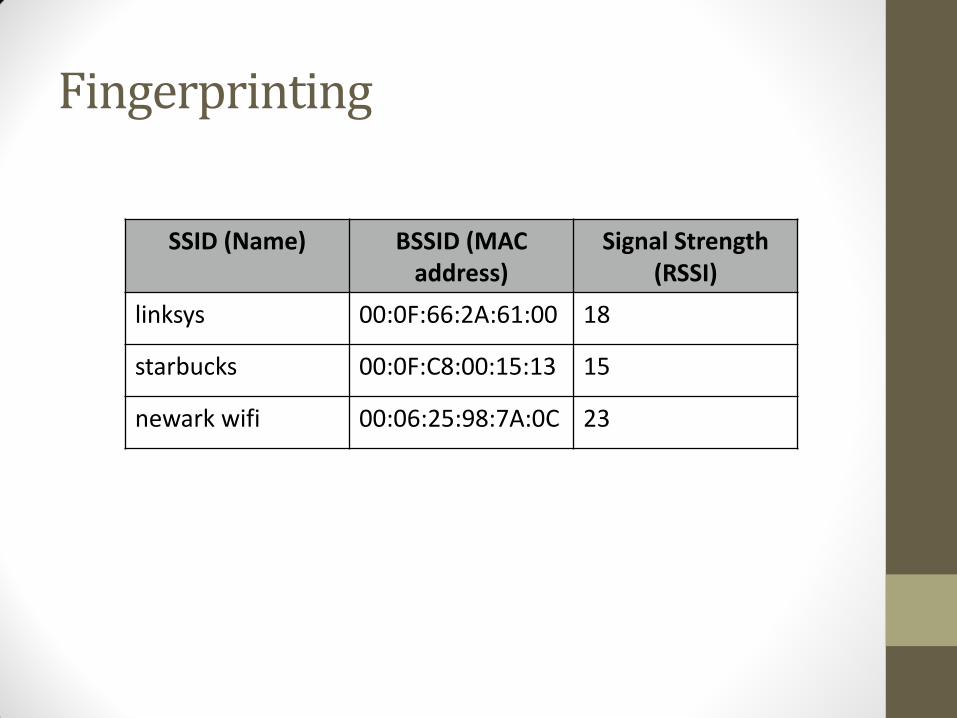
Fingerprinting
SSID (Name) BSSID (MAC address)
Signal Strength (RSSI)
linksys 00:0F:66:2A:61:00 18
starbucks 00:0F:C8:00:15:13 15
newark wifi 00:06:25:98:7A:0C 23
28
Fingerprinting
• Easier than modeling
• Requires a dense site survey
• Usually better for symbolic localization
• Spatial differentiability
• Temporal stability
Received Signal Strength (RSS) Profiling Measurements
• Construct a form of map of the signal strength behavior in the coverage area
• The map is obtained:
• Offline by a priori measurements
• Online using sniffing devices deployed at known locations
• They have been mainly used for location estimation in WLANs
Received Signal Strength (RSS) Profiling Measurements • Different nodes:
• Anchor nodes
• Non-anchor nodes,
• A large number of sample points (e.g., sniffing devices)
• At each sample point, a vector of signal strengths is obtained • jth entry corresponding to the jth anchor’s transmitted signal
• The collection of all these vectors provides a map of the whole region
• The collection constitutes the RSS model
• It is unique with respect to the anchor locations and the environment
• The model is stored in a central location
• A non-anchor node can estimate its location using the RSS measurements from anchors
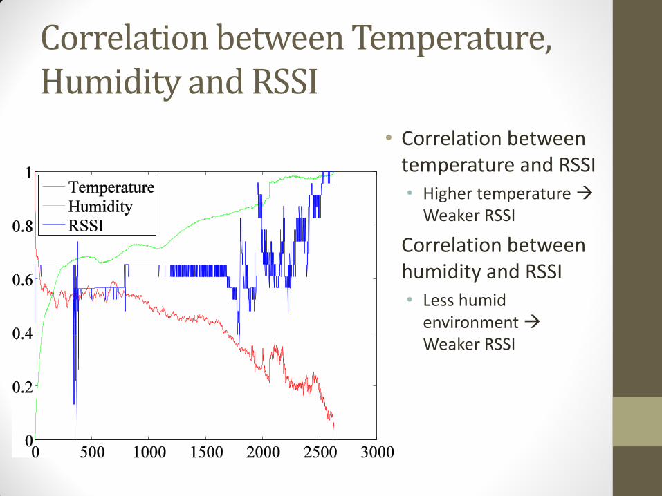
Correlation between Temperature, Humidity and RSSI
• Correlation between temperature and RSSI • Higher temperature
Weaker RSSI
• Correlation between humidity and RSSI • Less humid
environment Weaker RSSI
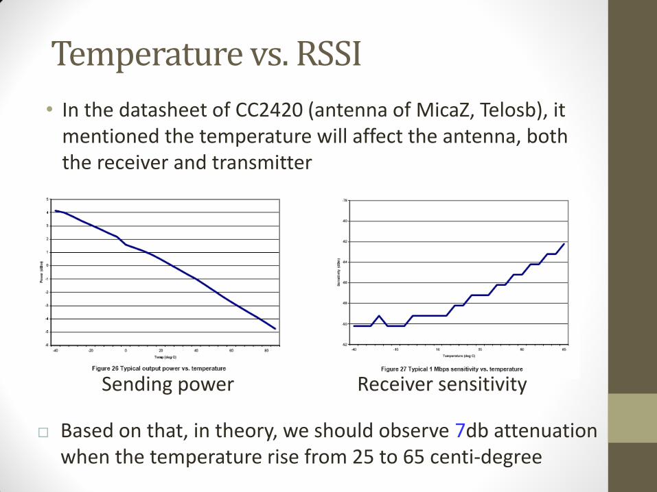
Temperature vs. RSSI
• In the datasheet of CC2420 (antenna of MicaZ, Telosb), it mentioned the temperature will affect the antenna, both the receiver and transmitter
Sending power Receiver sensitivity
Based on that, in theory, we should observe 7db attenuation when the temperature rise from 25 to 65 centi-degree
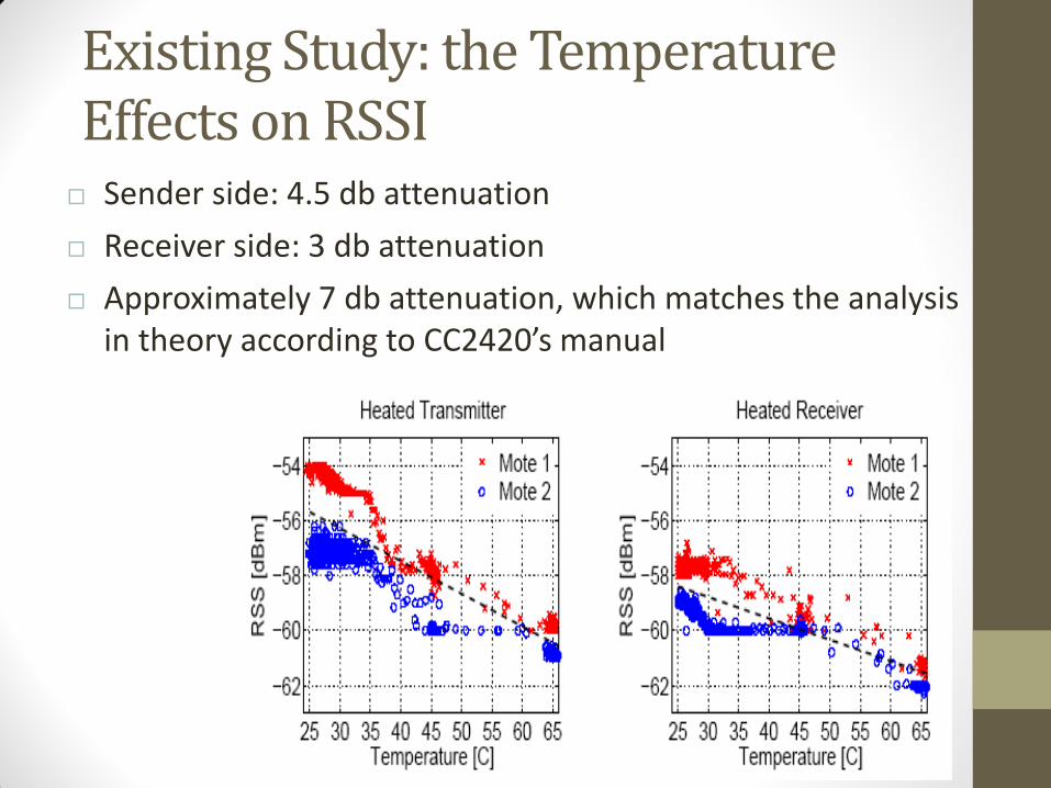
Existing Study: the Temperature Effects on RSSI Sender side: 4.5 db attenuation
Receiver side: 3 db attenuation
Approximately 7 db attenuation, which matches the analysis in theory according to CC2420’s manual
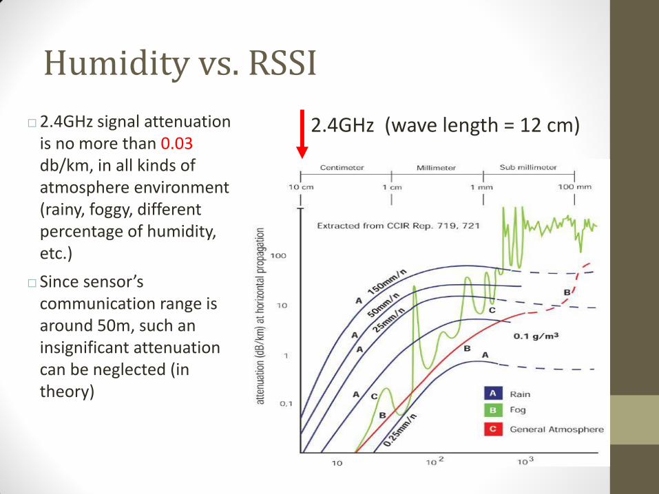
2.4GHz (wave length = 12 cm)
Humidity vs. RSSI
2.4GHz signal attenuation is no more than 0.03 db/km, in all kinds of atmosphere environment (rainy, foggy, different percentage of humidity, etc.)
Since sensor’s communication range is around 50m, such an insignificant attenuation can be neglected (in theory)
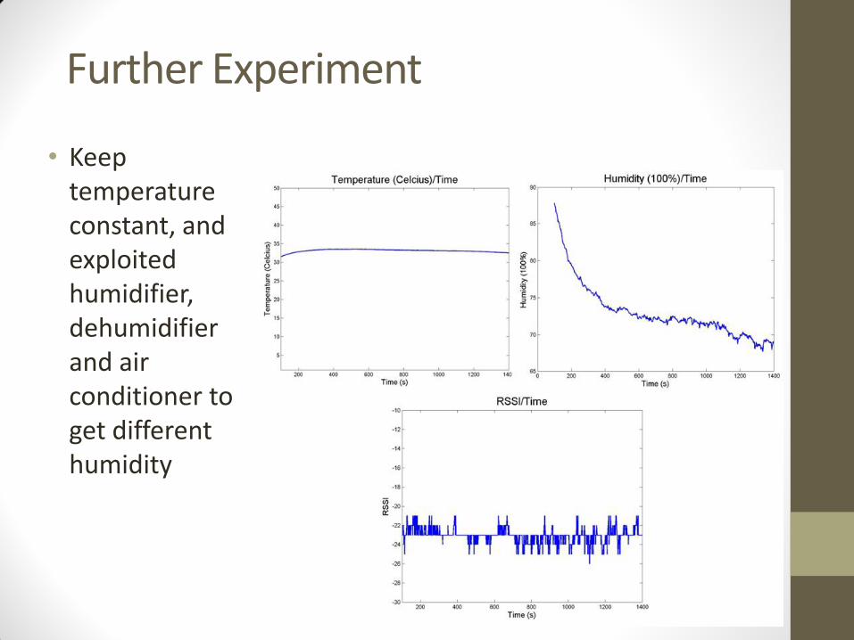
Further Experiment
• Keep temperature constant, and exploited humidifier, dehumidifier and air conditioner to get different humidity
Brief Conclusions
• We concluded that temperature can affect the transmission of WSNs significantly
• Taking account of temperature effects is necessary in designing of WSNs in some challenging environment, since sometime high temperature can break down the original designed topology
• We also verified that the variation of humidity would not actually affect the functionality of WSNs
Outline
• Defining location
• Methods for determining location
• Triangulation, trilateration, RSSI, etc.
• Location Systems • GPS
• Active Badge, MIL, Active Bat, Cricket
• RSS-based indoor localization
• RSS-based smartphone indoor localization
• Power-line based localization
• Passive location tracking
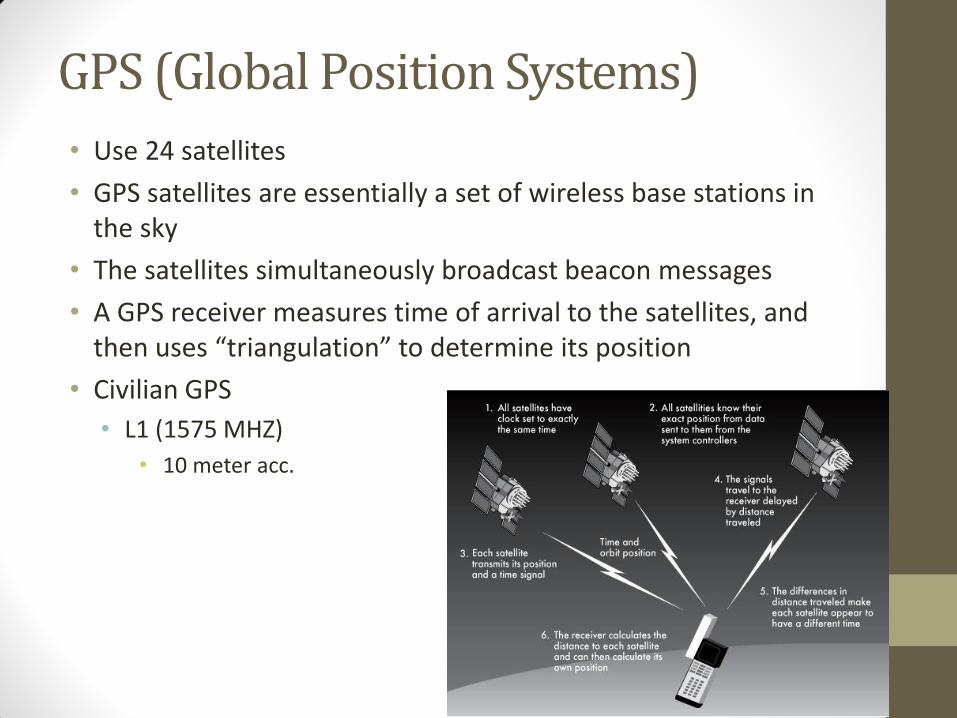
GPS (Global Position Systems)
• Use 24 satellites
• GPS satellites are essentially a set of wireless base stations in the sky
• The satellites simultaneously broadcast beacon messages
• A GPS receiver measures time of arrival to the satellites, and then uses “triangulation” to determine its position
• Civilian GPS
• L1 (1575 MHZ)
• 10 meter acc.
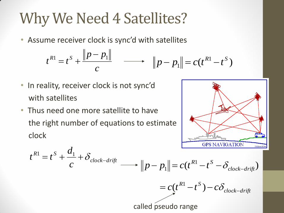
Why We Need 4 Satellites? • Assume receiver clock is sync’d with satellites
• In reality, receiver clock is not sync’d
with satellites
• Thus need one more satellite to have
the right number of equations to estimate
clock
driftclock
SR
c
dtt 11
)( 1
1 driftclock
SR ttcpp
driftclock
SR cttc )( 1
called pseudo range
c
pptt SR 11
)( 1
1
SR ttcpp
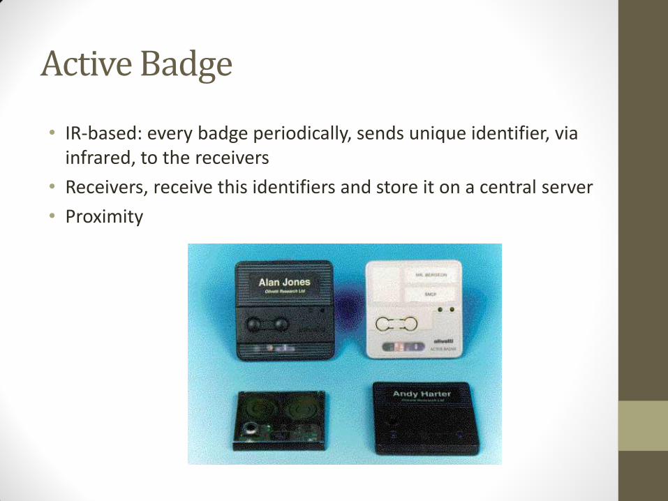
Active Badge
• IR-based: every badge periodically, sends unique identifier, via infrared, to the receivers
• Receivers, receive this identifiers and store it on a central server
• Proximity
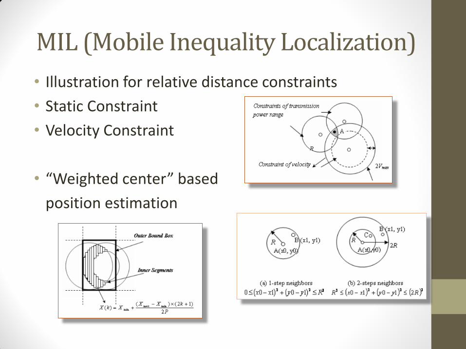
MIL (Mobile Inequality Localization)
• Illustration for relative distance constraints
• Static Constraint
• Velocity Constraint
• “Weighted center” based
position estimation
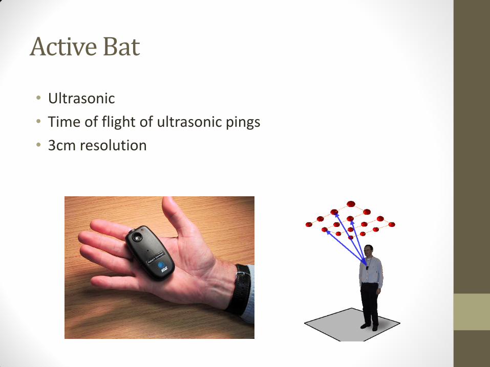
Active Bat
• Ultrasonic
• Time of flight of ultrasonic pings
• 3cm resolution
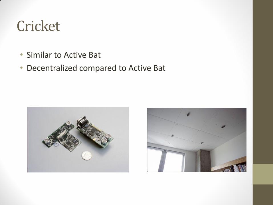
Cricket
• Similar to Active Bat
• Decentralized compared to Active Bat
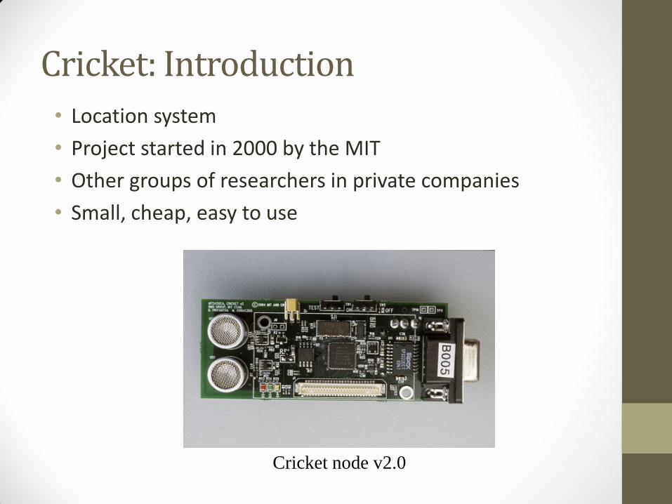
Cricket: Introduction
• Location system
• Project started in 2000 by the MIT
• Other groups of researchers in private companies
• Small, cheap, easy to use
Cricket node v2.0
Cricket: 5 Specific Goals • User privacy
• location-support system, not location-tracking system
• position known only by the user
• Decentralized administration
• easier for a scalable system
• each space (e.g. a room) owned by a beacon
• Network heterogeneity
• need to decouple the system from other data communication protocols (e.g. Ethernet, WLAN)
• Cost
• less than U.S. $10 per node
• Room-sized granularity
• regions determined within one or two square feet
Cricket: Determination of the Distance
• First version • purely RF-based system
• problems due to RF propagation within buildings
• Second version • combination of RF and ultrasound hardware
• measure of the one-way propagation time of the ultrasonic signals emitted by a node
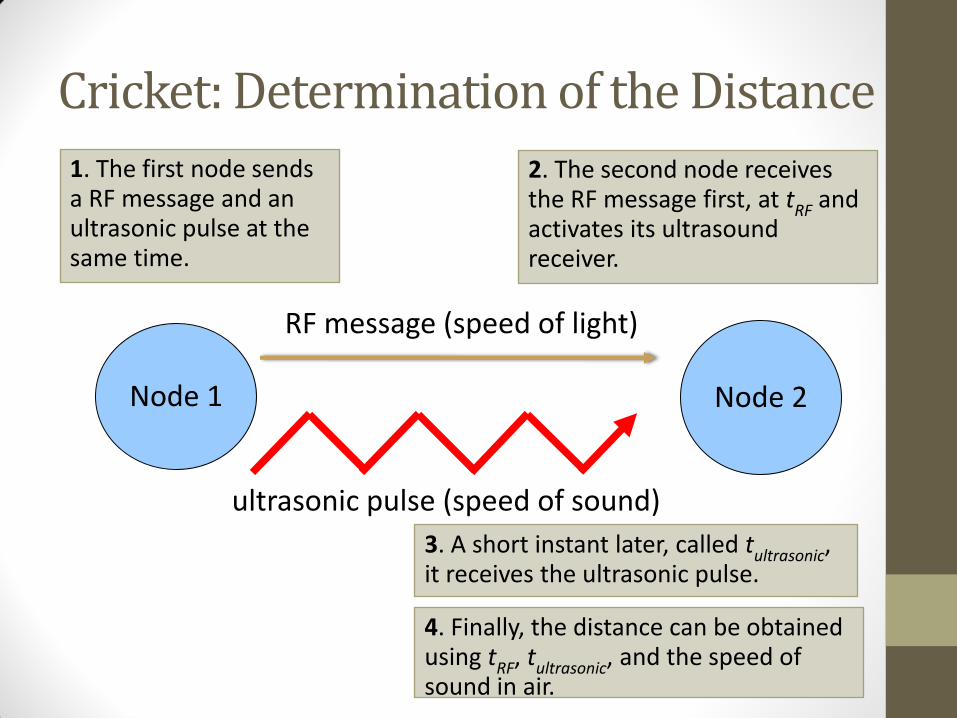
• main idea : information about the space periodically broadcasted concurrently over RF, together with an ultrasonic pulse
• speed of sound in air : about 340 m/s
• speed of light : about 300 000 000 m/s
Cricket: Determination of the Distance
Node 1
RF message (speed of light)
ultrasonic pulse (speed of sound)
1. The first node sends a RF message and an ultrasonic pulse at the same time.
2. The second node receives the RF message first, at tRF and activates its ultrasound receiver.
3. A short instant later, called tultrasonic, it receives the ultrasonic pulse.
4. Finally, the distance can be obtained using tRF, tultrasonic, and the speed of sound in air.
Node 2
Cricket: Difficulties • Collisions
• no implementation of a full-edged carrier-sense-style channel-access protocol to maintain simplicity and reduce overall energy consumption
• use of a decentralized randomized transmission algorithm to minimize collisions
• Physical layer
• decoding algorithm to overcome the effects of ultrasound multipath and RF interferences
• Tracking to improve accuracy
• a least-squares minimization (LSQ)
• an extended Kalman filter (EKF)
• outlier rejection
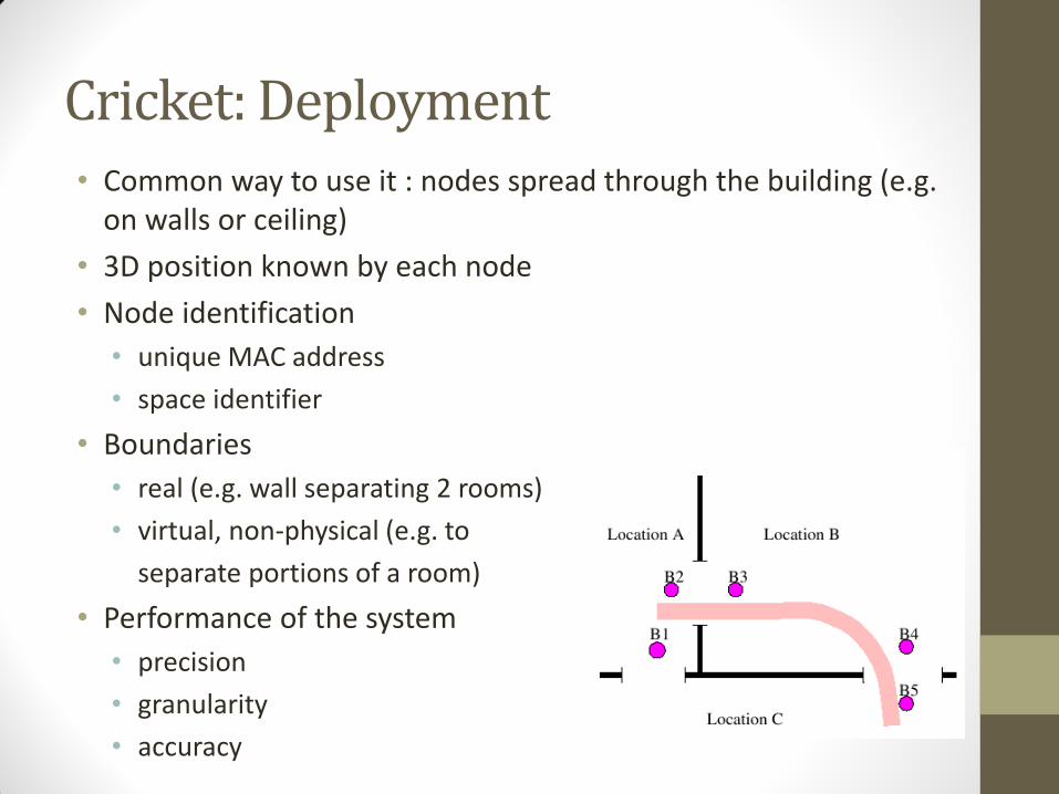
Cricket: Deployment • Common way to use it : nodes spread through the building (e.g.
on walls or ceiling)
• 3D position known by each node
• Node identification
• unique MAC address
• space identifier
• Boundaries
• real (e.g. wall separating 2 rooms)
• virtual, non-physical (e.g. to
separate portions of a room)
• Performance of the system
• precision
• granularity
• accuracy
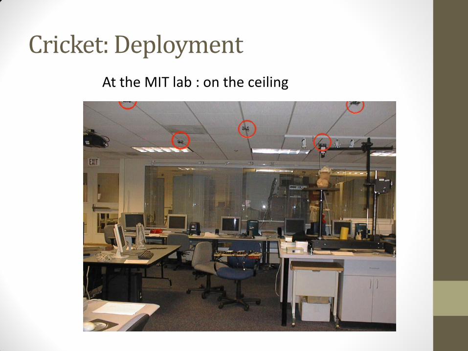
Cricket: Deployment
At the MIT lab : on the ceiling
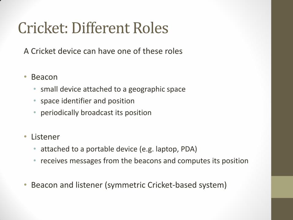
Cricket: Different Roles
A Cricket device can have one of these roles
• Beacon
• small device attached to a geographic space
• space identifier and position
• periodically broadcast its position
• Listener
• attached to a portable device (e.g. laptop, PDA)
• receives messages from the beacons and computes its position
• Beacon and listener (symmetric Cricket-based system)
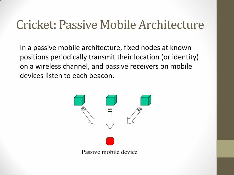
Cricket: Passive Mobile Architecture
In a passive mobile architecture, fixed nodes at known positions periodically transmit their location (or identity) on a wireless channel, and passive receivers on mobile devices listen to each beacon.
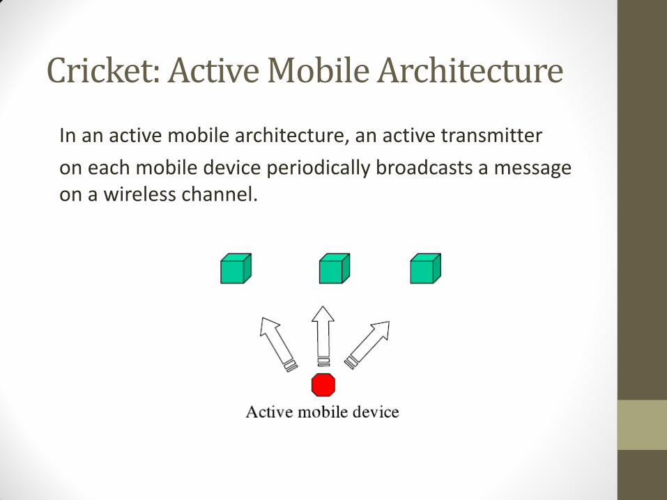
Cricket: Active Mobile Architecture
In an active mobile architecture, an active transmitter
on each mobile device periodically broadcasts a message on a wireless channel.
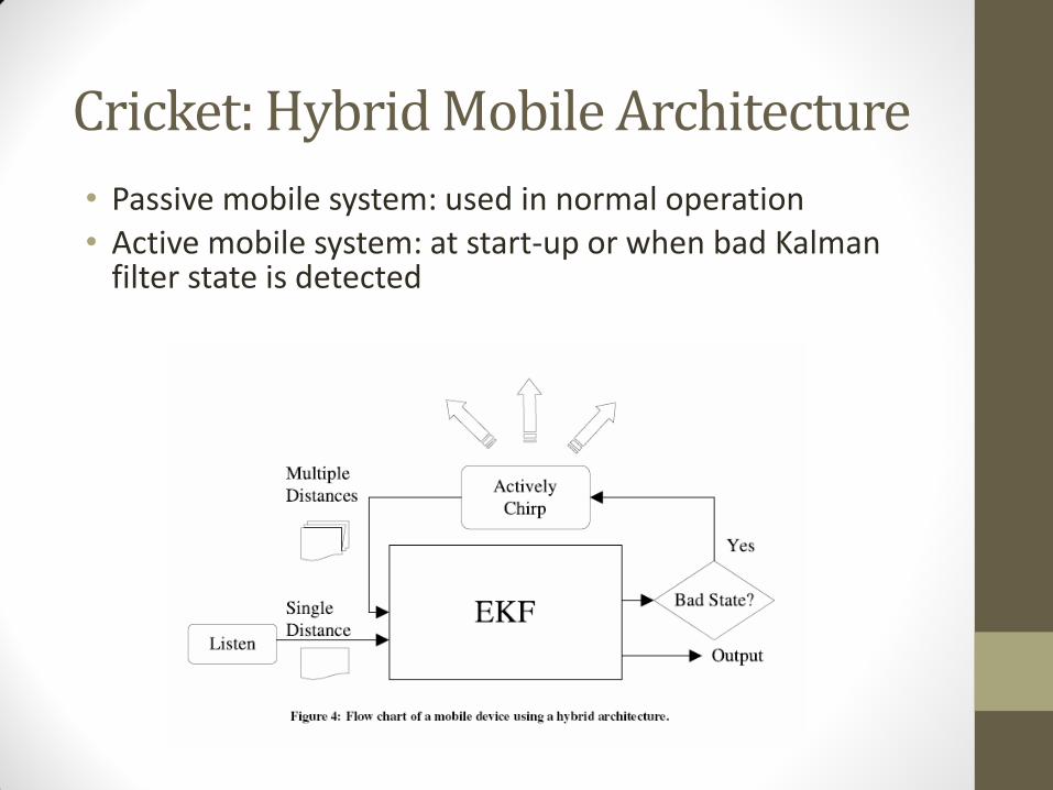
Cricket: Hybrid Mobile Architecture
• Passive mobile system: used in normal operation • Active mobile system: at start-up or when bad Kalman
filter state is detected
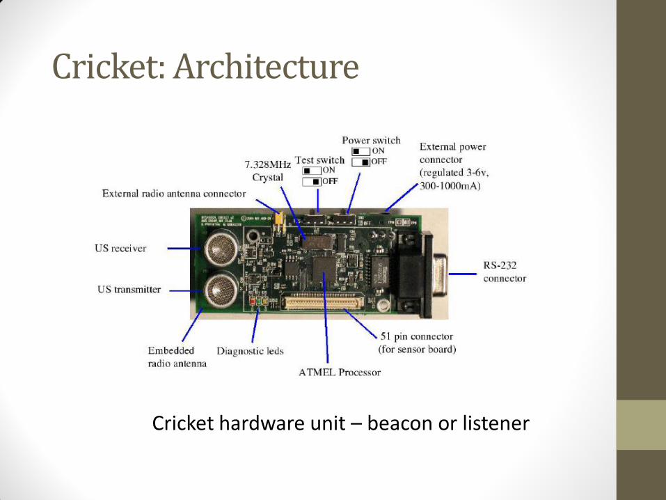
Cricket: Architecture
Cricket hardware unit – beacon or listener
• Microcontroller
• the Atmega 128L operating at 7.3728 Mhz in active and 32.768 kHz in sleep mode
• operates at 3V and draws about 8mA(active mode) or 8μA(sleep mode)
• RF transceiver
• the CC1000 RF configured to operate at 433 Mhz
• bandwidth bounded to 19.2 kilobits/s
Cricket: Architecture
• Ultrasonic transmitter
• 40 kHz piezo-electric open-air ultrasonic transmitter
• generates ultrasonic pulses of duration 125 μs
• voltage multiplier module generates 12 V from the 3 V supply voltage to drive the ultrasonic transmitter
• Ultrasonic receiver
• open-air type piezo-electric sensor
• output is connected to a two-stage amplifier with a programmable voltage gain between 70 dB and 78 dB
Cricket: Architecture
• RS 232 interface
• used to attach a host device to the Cricket node
• Temperature sensor
• allows to compensate for variations in the speed of sound with temperature
• Unique ID
• an 8-byte hardware ID, uniquely identifies every Cricket node
• Powering the Beacons and Listeners
• each Cricket node may be powered using two AA batteries, a power adapter, or solar cells
• beacon can operate on two AA batteries for 5 to 6 weeks
Cricket: Architecture
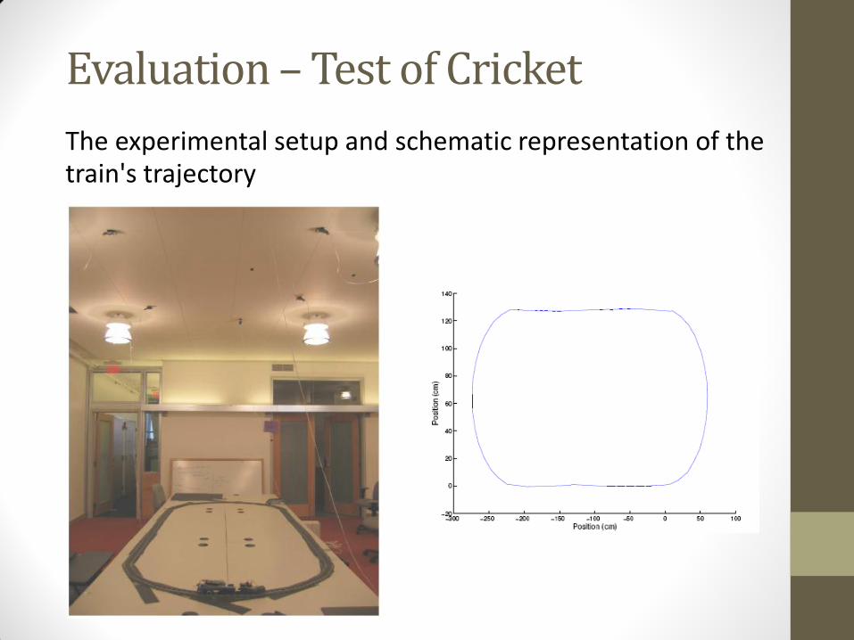
The experimental setup and schematic representation of the train's trajectory
Evaluation – Test of Cricket
Experimental facts
• Three architectures: passive mobile, active mobile, and hybrid with Extended Kalman Filter (EKF) or least-squares minimization (LSQ)
• Computer-controlled Lego train set running at six different speeds: 0.34 m/s, 0.56 m/s, 0.78 m/s, 0.98 m/s, 1.21 m/s, and 1.43 m/s
• Multiple beacons (five or six in all experiments) interacting with one another
• Gathered about 15,000 individual distance estimates in the active mobile architecture and about 3,000 distance estimates in the passive mobile architecture
Evaluation – Test of Cricket
Evaluation – Test of Cricket
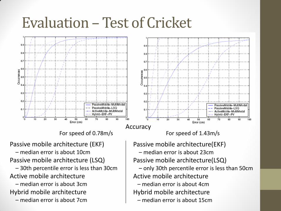
For speed of 0.78m/s For speed of 1.43m/s
Passive mobile architecture (EKF) – median error is about 10cm
Passive mobile architecture (LSQ) – 30th percentile error is less than 30cm
Active mobile architecture – median error is about 3cm
Hybrid mobile architecture – median error is about 7cm
Passive mobile architecture(EKF) – median error is about 23cm
Passive mobile architecture(LSQ) – only 30th percentile error is less than 50cm
Active mobile architecture – median error is about 4cm
Hybrid mobile architecture – median error is about 15cm
Accuracy
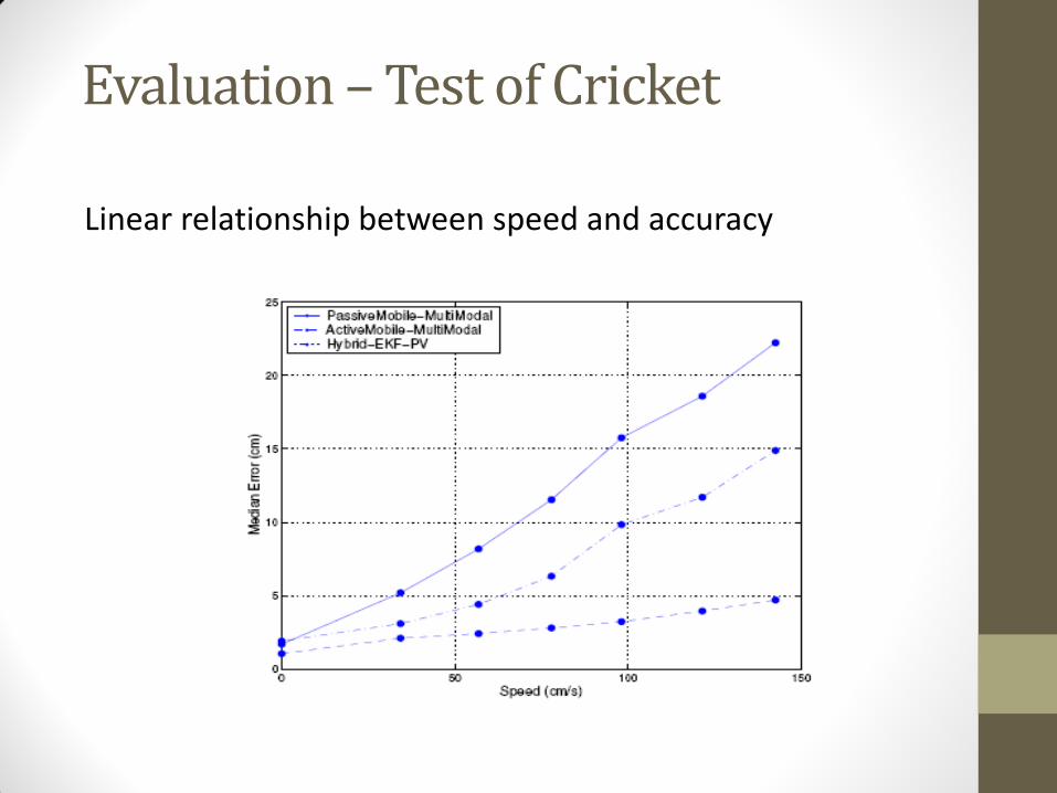
Linear relationship between speed and accuracy
Evaluation – Test of Cricket
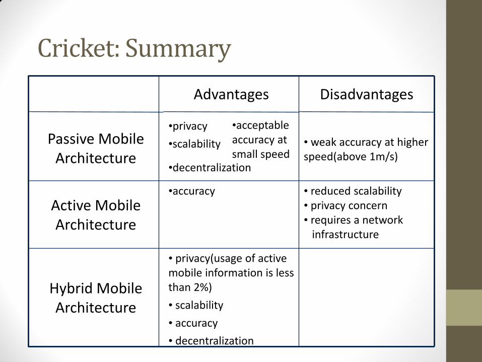
•decentralization
•acceptable accuracy at small speed
• privacy(usage of active mobile information is less than 2%)
• scalability
• accuracy
• decentralization
Hybrid Mobile Architecture
• reduced scalability • privacy concern • requires a network infrastructure
•accuracy
Active Mobile Architecture
• weak accuracy at higher speed(above 1m/s)
•privacy
•scalability
Passive Mobile Architecture
Disadvantages Advantages
Cricket: Summary

Outline
• Defining location
• Methods for determining location
• Triangulation, trilateration, RSSI, etc.
• Location Systems • GPS
• Active Badge, MIL, Active Bat, Cricket
• RSS-based indoor localization
• RSS-based smartphone indoor localization
• Power-line based localization
• Passive location tracking
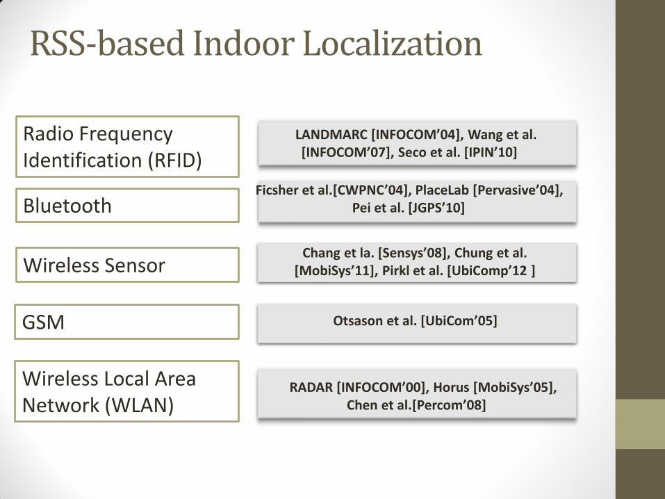
RSS-based Indoor Localization
Radio Frequency Identification (RFID)
Bluetooth
Wireless Sensor
LANDMARC [INFOCOM’04], Wang et al. [INFOCOM’07], Seco et al. [IPIN’10]
RADAR [INFOCOM’00], Horus [MobiSys’05], Chen et al.[Percom’08]
Wireless Local Area Network (WLAN)
Ficsher et al.[CWPNC’04], PlaceLab [Pervasive’04], Pei et al. [JGPS’10]
GSM
Chang et la. [Sensys’08], Chung et al. [MobiSys’11], Pirkl et al. [UbiComp’12 ]
Otsason et al. [UbiCom’05]
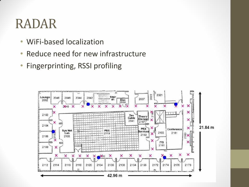
RADAR • WiFi-based localization
• Reduce need for new infrastructure
• Fingerprinting, RSSI profiling
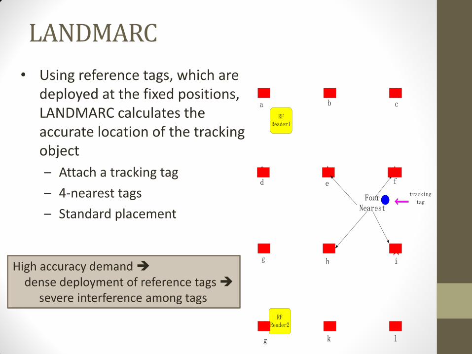
• Using reference tags, which are deployed at the fixed positions, LANDMARC calculates the accurate location of the tracking object
– Attach a tracking tag
– 4-nearest tags
– Standard placement
LANDMARC
a b c
d e f
g h i
g k l
RFReader1
RFReader2
FourNearest
trackingtag
High accuracy demand dense deployment of reference tags severe interference among tags
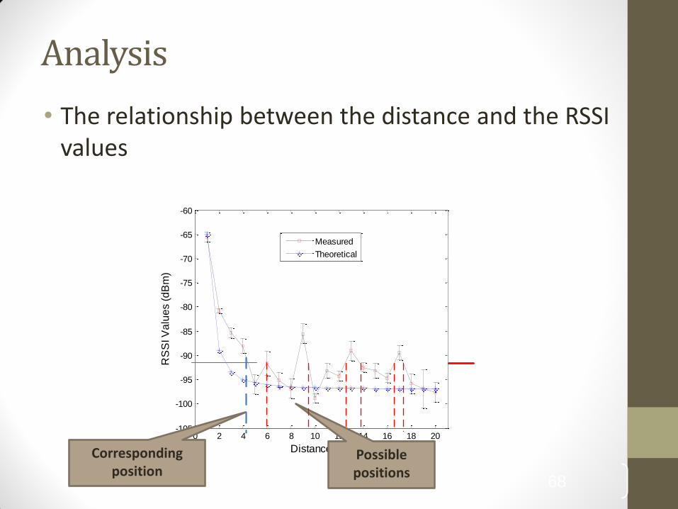
Analysis
• The relationship between the distance and the RSSI values
68
0 2 4 6 8 10 12 14 16 18 20-105
-100
-95
-90
-85
-80
-75
-70
-65
-60
Distance (m)
RS
SI V
alu
es (
dB
m)
Measured
Theoretical
Corresponding position
Possible positions
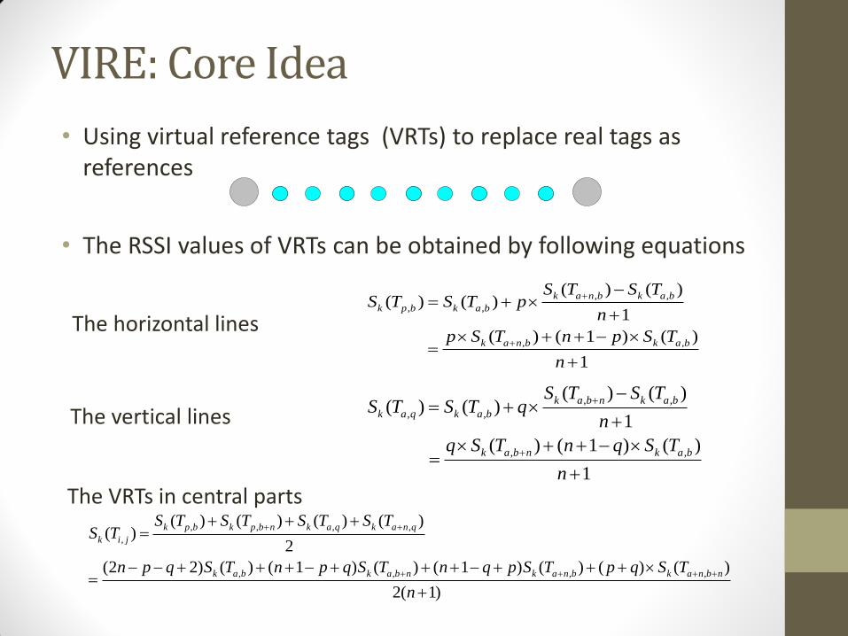
VIRE: Core Idea
• Using virtual reference tags (VRTs) to replace real tags as references
• The RSSI values of VRTs can be obtained by following equations
, ,
, ,
, ,
( ) ( )( ) ( )
1
( ) ( 1 ) ( )
1
k a n b k a b
k p b k a b
k a n b k a b
S T S TS T S T p
n
p S T n p S T
n
, ,
, ,
, ,
( ) ( )( ) ( )
1
( ) ( 1 ) ( )
1
k a b n k a b
k a q k a b
k a b n k a b
S T S TS T S T q
n
q S T n q S T
n
, , , ,
,
, , , ,
( ) ( ) ( ) ( )( )
2
(2 2) ( ) ( 1 ) ( ) ( 1 ) ( ) ( ) ( )
2( 1)
k p b k p b n k a q k a n q
k i j
k a b k a b n k a n b k a n b n
S T S T S T S TS T
n p q S T n p q S T n q p S T p q S T
n
The horizontal lines
The vertical lines
The VRTs in central parts
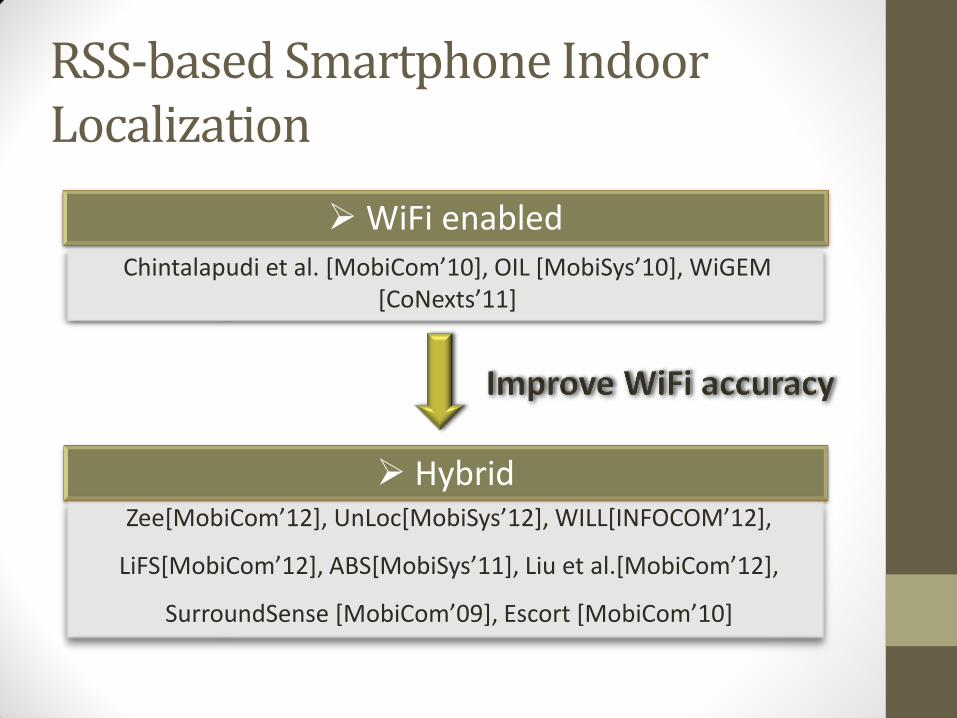
RSS-based Smartphone Indoor Localization
WiFi enabled Chintalapudi et al. [MobiCom’10], OIL [MobiSys’10], WiGEM
[CoNexts’11]
Hybrid Zee[MobiCom’12], UnLoc[MobiSys’12], WILL[INFOCOM’12],
LiFS[MobiCom’12], ABS[MobiSys’11], Liu et al.[MobiCom’12],
SurroundSense [MobiCom’09], Escort [MobiCom’10]
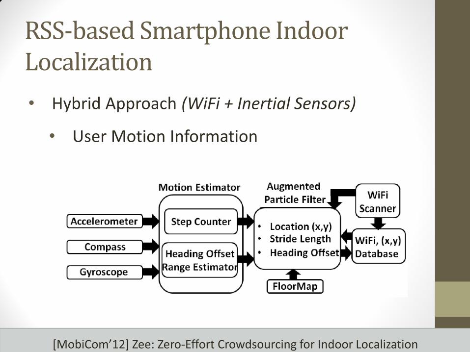
[MobiCom’12] Zee: Zero-Effort Crowdsourcing for Indoor Localization
• Hybrid Approach (WiFi + Inertial Sensors)
• User Motion Information
RSS-based Smartphone Indoor Localization
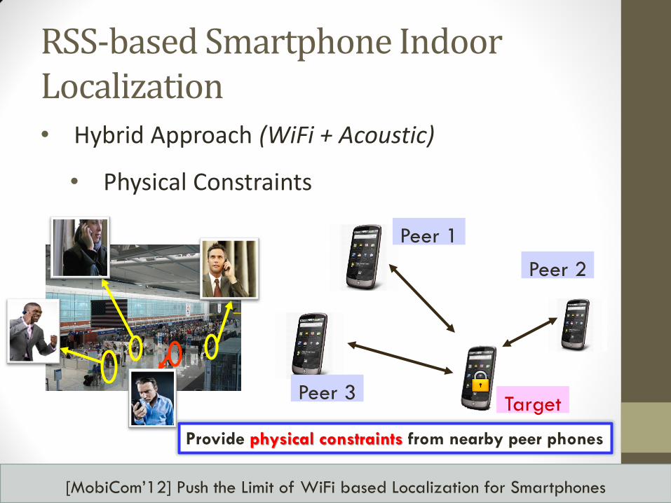
[MobiCom’12] Push the Limit of WiFi based Localization for Smartphones
Provide physical constraints from nearby peer phones
Target
Peer 1
Peer 2
Peer 3
• Hybrid Approach (WiFi + Acoustic)
• Physical Constraints
RSS-based Smartphone Indoor Localization
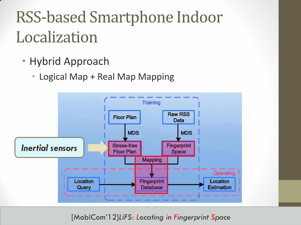
[MobiCom’12]LiFS: Locating in Fingerprint Space
Inertial sensors
RSS-based Smartphone Indoor Localization
• Hybrid Approach
• Logical Map + Real Map Mapping
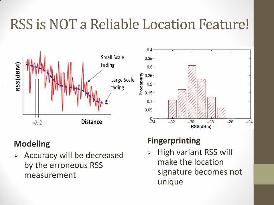
Modeling
Accuracy will be decreased by the erroneous RSS measurement
Fingerprinting
High variant RSS will make the location signature becomes not unique
RSS is NOT a Reliable Location Feature!
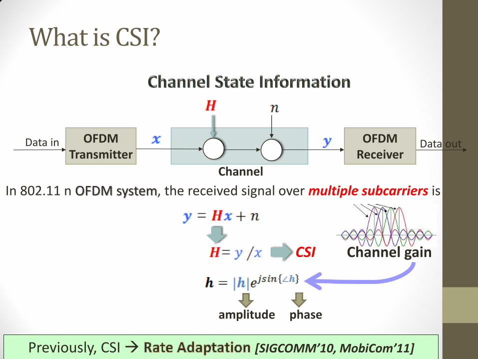
Data out OFDM Transmitter
Channel
Data in OFDM Receiver
What is CSI?
In 802.11 n OFDM system, the received signal over multiple subcarriers is
amplitude phase
Channel gain CSI
Previously, CSI [SIGCOMM’10, MobiCom’11]
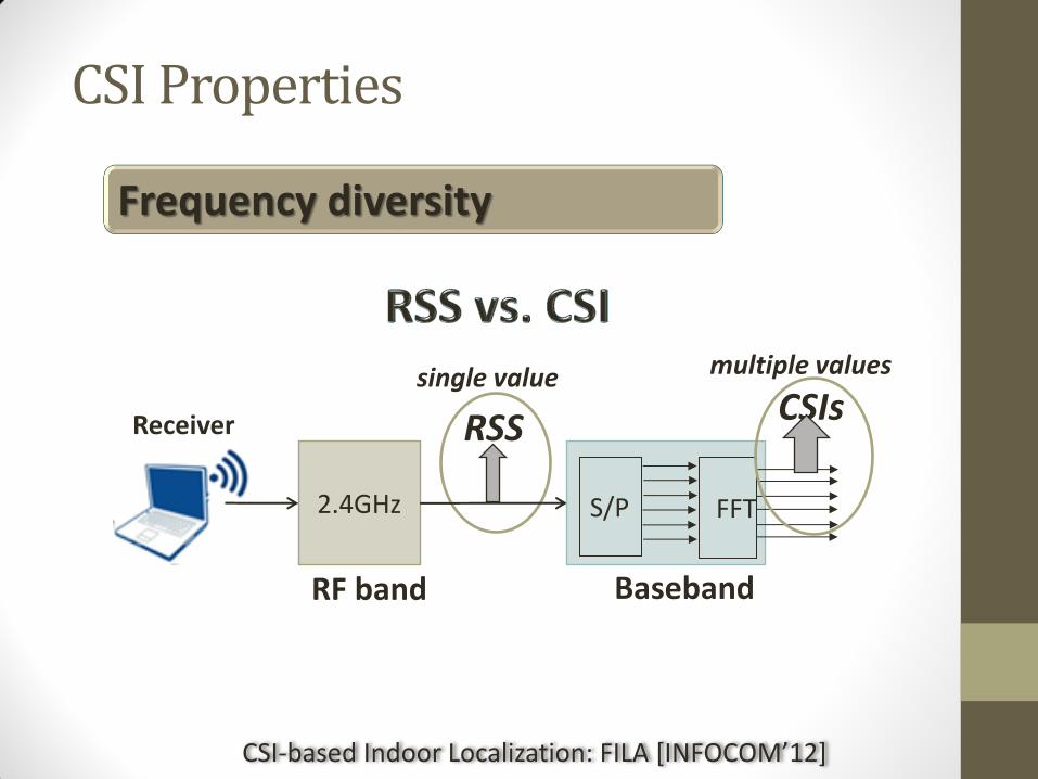
2.4GHz
Frequency diversity
single value
RSS Receiver CSIs
S/P FFT
Baseband
multiple values
RF band
CSI-based Indoor Localization: FILA [INFOCOM’12]
CSI Properties
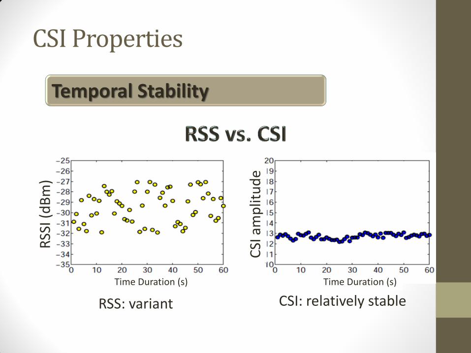
RSS: variant CSI: relatively stable
CSI Properties
CSI
am
plit
ud
e
RSS
I (d
Bm
)
Time Duration (s) Time Duration (s)
Temporal Stability
RSS 从RF BAND 得到
CSI 从BASE BAND得到
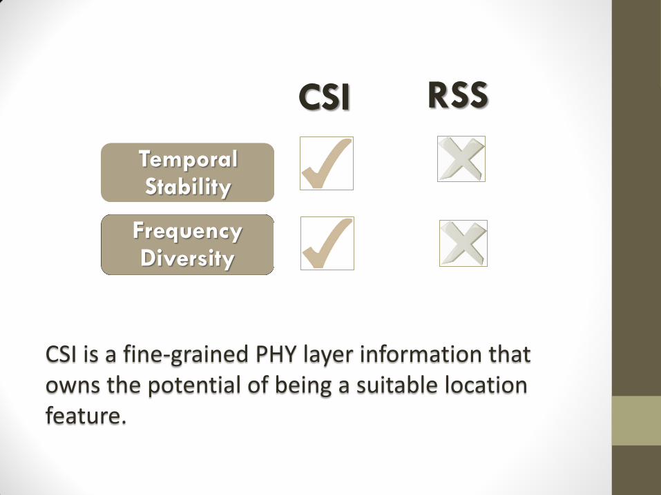
CSI RSS
Frequency Diversity
Temporal Stability
CSI is a fine-grained PHY layer information that owns the potential of being a suitable location feature.
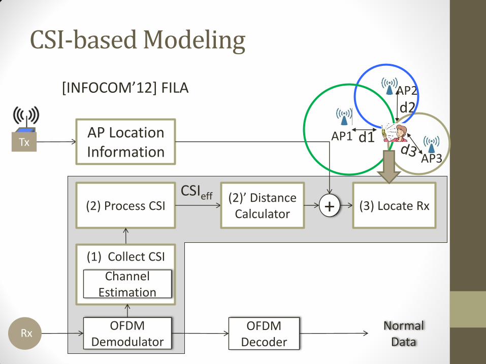
CSI-based Modeling
Tx AP Location Information
(2) Process CSI CSIeff (2)’ Distance
Calculator
OFDM Demodulator
OFDM Decoder
Rx Normal
Data
+ (3) Locate Rx
(1) Collect CSI
Channel Estimation
AP1
d2 AP2
AP3
d1
Two processing mechanisms:
#1 Time-domain Multipath
Mitigation
#2 Frequency-domain Fading
Compensation
Distance Estimation
[INFOCOM’12] FILA
Outline
• Defining location
• Methods for determining location
• Triangulation, trilateration, RSSI, etc.
• Location Systems • GPS
• Active Badge, MIL, Active Bat, Cricket
• RSS-based indoor localization
• RSS-based smartphone indoor localization
• Power-line based localization
• Passive location tracking
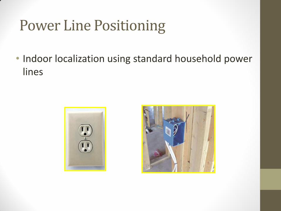
Power Line Positioning
• Indoor localization using standard household power lines
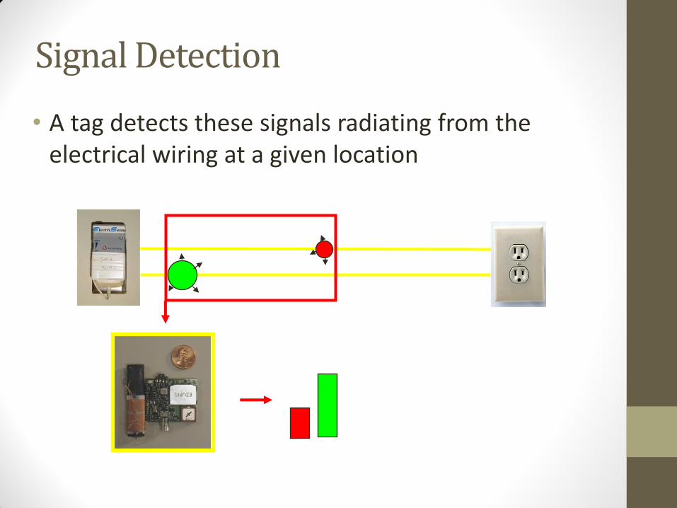
Signal Detection
• A tag detects these signals radiating from the electrical wiring at a given location
83
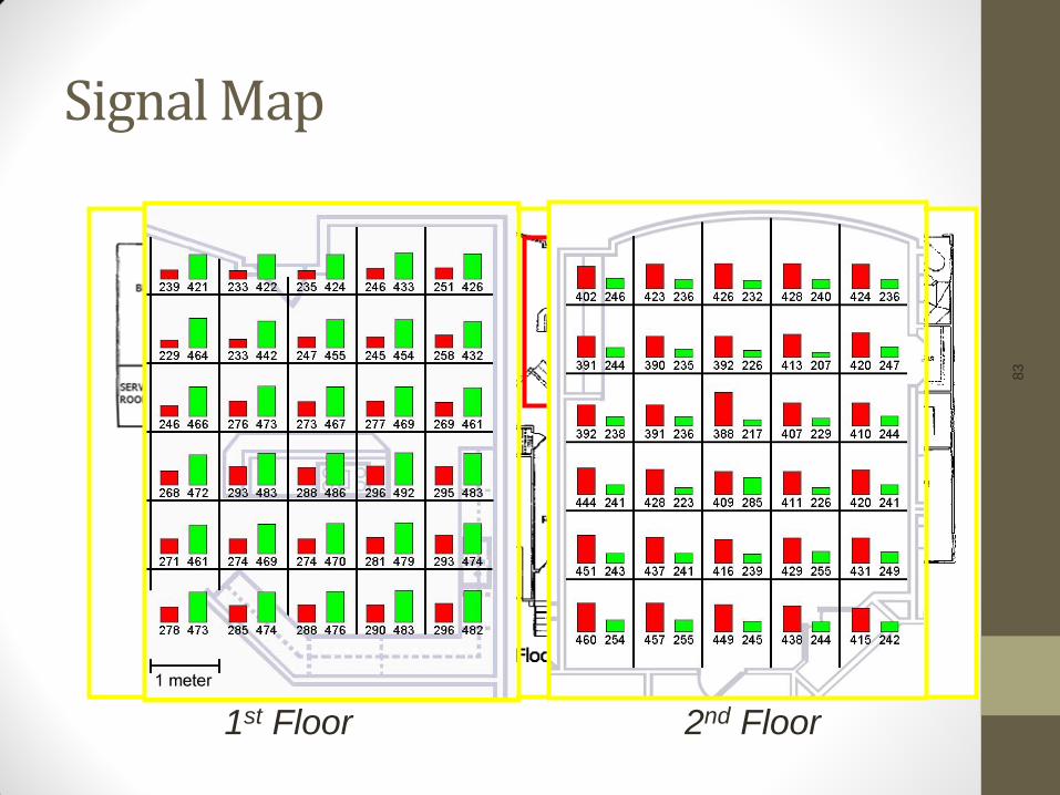
Signal Map
1st Floor 2nd Floor
Outline
• Defining location
• Methods for determining location
• Triangulation, trilateration, RSSI, etc.
• Location Systems • GPS
• Active Badge, Active Bat, Cricket, Ubisense, Place Lab, ROSUM
• RSS-based indoor localization
• RSS-based smartphone indoor localization
• Power-line based localization
• Passive location tracking
Passive Location Tracking
• No need to carry a tag or device • Hard to determine the identity of the person
• Requires more infrastructure (potentially)
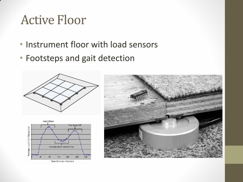
Active Floor
• Instrument floor with load sensors
• Footsteps and gait detection
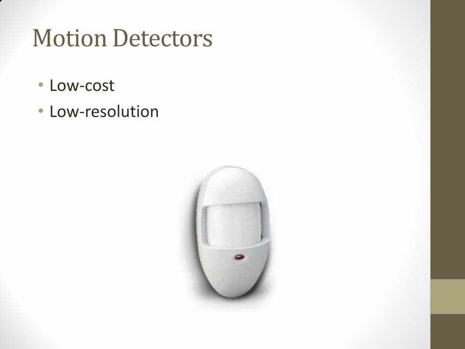
Motion Detectors
• Low-cost
• Low-resolution
Computer Vision
• Leverage existing infrastructure
• Requires significant communication and computational resources
• CCTV
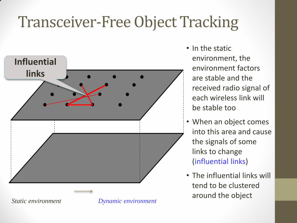
Transceiver-Free Object Tracking
Static environment Dynamic environment
Influential links
• In the static environment, the environment factors are stable and the received radio signal of each wireless link will be stable too
• When an object comes into this area and cause the signals of some links to change (influential links)
• The influential links will tend to be clustered around the object
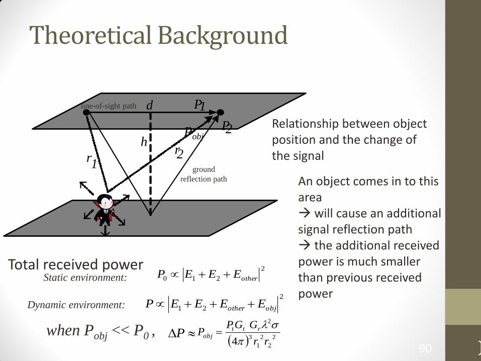
Theoretical Background
90
2
210 otherEEEP
2
21 objother EEEEP
when Pobj << P0 ,
Static environment:
Dynamic environment:
P 2
2
2
1
3
2
4 rr
GGPP rtt
obj
Pobj
d
r 1
r 2 h
P 1
P 2 Relationship between object position and the change of the signal
An object comes in to this area will cause an additional signal reflection path the additional received power is much smaller than previous received power
Total received power
ground
reflection path
line-of-sight path
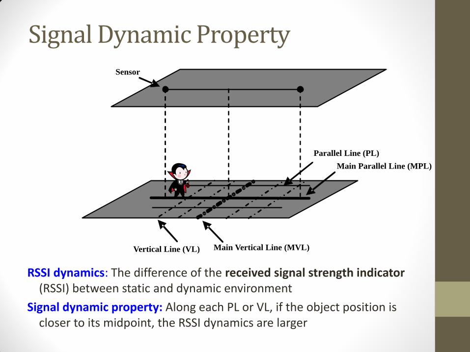
Signal Dynamic Property
RSSI dynamics: The difference of the received signal strength indicator (RSSI) between static and dynamic environment
Signal dynamic property: Along each PL or VL, if the object position is closer to its midpoint, the RSSI dynamics are larger
Main Parallel Line (MPL)
Sensor
Main Vertical Line (MVL) Vertical Line (VL)
Parallel Line (PL)
DDC (Distributed Dynamic Clustering)
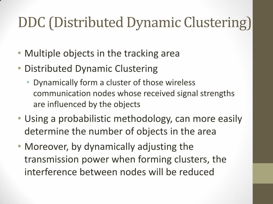
• Multiple objects in the tracking area
• Distributed Dynamic Clustering
• Dynamically form a cluster of those wireless communication nodes whose received signal strengths are influenced by the objects
• Using a probabilistic methodology, can more easily determine the number of objects in the area
• Moreover, by dynamically adjusting the transmission power when forming clusters, the interference between nodes will be reduced
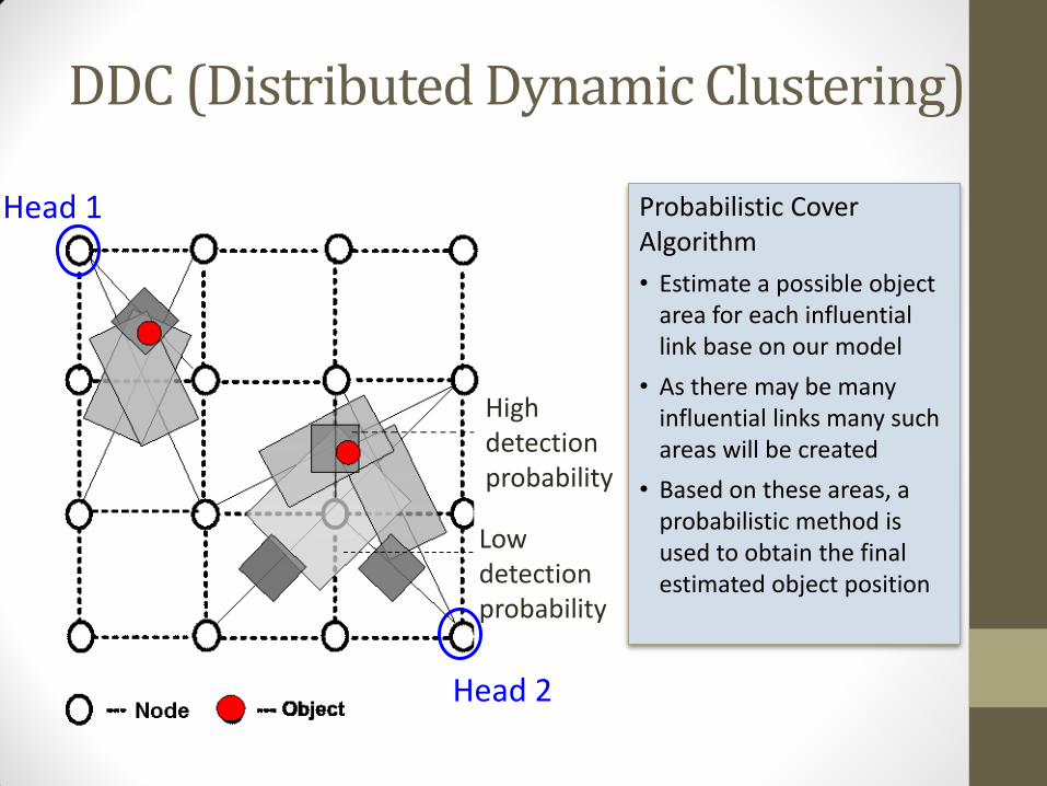
DDC (Distributed Dynamic Clustering)
High detection probability
Low detection probability
Head 2
Head 1 Probabilistic Cover Algorithm
• Estimate a possible object area for each influential link base on our model
• As there may be many influential links many such areas will be created
• Based on these areas, a probabilistic method is used to obtain the final estimated object position

The End!