
LOAD MOMENT INDICATOR SYSTEM - Basil Equipment
44
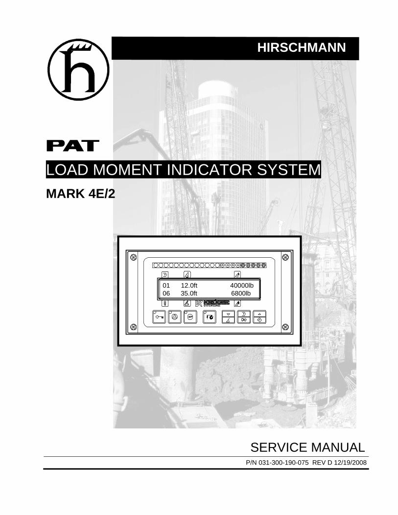
HIRSCHMANN LOAD MOMENT INDICATOR SYSTEM MARK 4E/2 01 12.0ft 40000lb 06 35.0ft 6800lb SERVICE MANUAL P/N 031-300-190-075 REV D 12/19/2008
Transcript of LOAD MOMENT INDICATOR SYSTEM - Basil Equipment
HIRSCHMANN
LOAD MOMENT INDICATOR SYSTEM
MARK 4E/2
01 12.0ft 40000lb06 35.0ft 6800lb
SERVICE MANUAL P/N 031-300-190-075 REV D 12/19/2008

Service Manual Mark 4E/2
©Hirschmann Rev. D 12/19/08 WG/SC 190075_D
NOTICE
Hirschmann, Inc. makes no warranty of any kind with regard to this material, including, but not limited to, the implied warranties of merchantability and/or its fitness for a particular purpose. Hirschmann, Inc. will not be liable for errors contained in this manual or for incidental or consequential damages in connection with the furnishing, performance, or use of this manual. This document contains proprietary information, which is protected by copyright, and all rights are reserved. No part of this document may be photocopied, reproduced, or translated to another language without the prior written consent of Hirschmann, Inc. Hirschmann, Inc. reserves proprietary rights to all drawings, photos and the data contained therein. The drawings, photos and data are confidential and cannot be used or reproduced without the written consent of Hirschmann, Inc. The drawings and/or photos are subject to technical modification without prior notice. All information in this document is subject to change without notice. MANUAL REVISIONS
REV DATE NAME DESCRIPTION
- 7/25/2002 SB Created service manual, ECN 02-205 A 9/15/2003 SB Add Console/Central Unit Connections, ECN 03-115 B 4/29/2008 SC ECN 08-071 (include PAT sensors & revise wiring) C 10/10/2008 WG ECN 08-149 (revise wiring) D 12/19/2008 WG ECN 08-204 (Wiring diagrams added to end of manual)
© 2008 Hirschmann Automation and Control, Chambersburg, PA 17201, USA

Service Manual Mark 4E/2
©Hirschmann Rev. D 12/19/08 WG/SC 190075_D
TABLE OF CONTENTS
1 MECHANICAL DESCRIPTION OF THE COMPONENTS.................................................1
2 MECHANICAL AND ELECTRICAL DESCRIPTION OF THE CENTRAL UNIT................2
3 BASIC ADJUSTMENT OF THE HARDWARE ..................................................................3
4 DEFINITIONS ....................................................................................................................4
5 DRAWINGS .......................................................................................................................5 5.1 WIRING DIAGRAM - CENTRAL UNIT SHUT OFF............................................................................. 5 5.2 CENTRAL PROCESSOR 12/24 VDC........................................................................................ 6 5.3 ELECTRICAL DIAGRAM – CENTRAL UNIT/CONSOLE.............................................................. 7 5.4 INDICATOR PANEL/CONSOLE 1-0118417.00 SPARE PARTS LIST ................................................ 8 5.5 ELECTRICAL DIAGRAM – CABLE REEL / A2B SWITCH ....................................................... 8 5.6 CABLE REEL PARTS LIST............................................................................................................ 9 5.7 ANTI-TWO BLOCK SWITCH (PAT)........................................................................................ 10 5.8 ANTI-TWO BLOCK SWITCH (KUEGER) ..................................................................................... 11 5.9 PRESSURE TRANSDUCER (250 BAR): 1-0108060.00 ............................................................... 12 5.10 PRESSURE TRANSDUCER CABLE ASSEMBLY ......................................................................... 12 5.11 PRESSURE TRANSDUCER (DAVS300 / 3401)........................................................................ 12 5.12 CABLE ASSEMBLY (PRESSURE TRANS), 031-300-060-693.................................................... 13 5.13 JUMPER CABLE ASSEMBLY FOR EXTENSION, 031-010-100-144 ............................................ 14 5.14 ROLLER SWITCH WIRING, 031-006-100-043.......................................................................... 14
6 LENGTH AND ANGLE SENSOR ADJUSTMENT...........................................................15 6.1 EPROM REPLACEMENT IN CENTRAL UNIT .................................................................................. 16 6.2 PISTON & ROD PRESSURE CHANNEL ADJUSTMENT................................................................... 17
6.2.1 Adjust pressure piston: ................................................................................................... 17 6.2.2 Adjust pressure Rod: ...................................................................................................... 17
6.3 LENGTH CABLE REPLACEMENT ................................................................................................ 18 7 TROUBLESHOOTING FLOW CHARTS .........................................................................19
7.1 GENERAL FLOWCHART ...................................................................................................... 19 7.2 LEVER LOCKOUT ACTIVATED ............................................................................................ 20 7.3 BLANK DISPLAY ................................................................................................................... 21 7.4 ANTI-TWO-BLOCK PROBLEM.............................................................................................. 23 7.5 LENGTH READING PROBLEM ............................................................................................. 26 7.6 ANGLE READING PROBLEM ............................................................................................... 27
8 ERROR CODES ..............................................................................................................28 8.1 OPERATOR ERROR CODE TABLE...................................................................................... 28 8.2 SYSTEM ERROR CODE TABLE ........................................................................................... 30
9 TROUBLESHOOTING MOISTURE.................................................................................32 9.1 WATER INGRESS...................................................................................................................... 32 9.2 CONDENSATION....................................................................................................................... 33
10 LMI SYSTEM TEST PROCEDURE .................................................................................34
11 APPENDIX.......................................................................................................................35


Mechanical Description Of The Components
©Hirschmann Rev. D 12/19/08 WG/SC 190075_D
1
1 MECHANICAL DESCRIPTION OF THE COMPONENTS Pressure Transducer: The pressure transducer transforms hydraulic pressure into an electric analogue voltage signal. Two pressure transducers are connected, one to the rod side and one to the piston side of the lift cylinder. The pressure transducer is connected to the central unit with a four conductor, double shielded cable. The power supply voltage is +12V. The output signal is 4.00ma at 0 pressure to 20.00ma at maximum pressure (300bar). Cable Reel: The cable reel houses the length-angle transducer, slip ring disc and slip ring pick up (to feed and return A-2-B signal). The PE cable goes through the drum and out to the tip where it is wired to the Anti-Two-Block switch. The reel is driven by a tensioned spring and should be handled with caution. The Length-Angle Transducer: The length-angle sensor (LWG) is a combination of two transducers in cable reel, fitted at the base section of the boom. It measures the length and the angle of the boom. A reeling drum drives a potentiometer, which is the length transducer. Part of the length transducer is the length cable on the drum, which is a two-conductor cable (shield and core). It is connected to the anti-two-block switch at the boom head and to a slip ring body in the LWG. The angle transducer is fitted in the cable reel. A pendulum drives the axle of the angle potentiometer. The power supply voltage for both is +12/24 vdc The output signal for the length transducer is: 4.00ma up to 20.00ma The output signal for the angle transducer is: 4.00ma at 90° to 20.00ma at 0° Anti-Two-Block Switch: The anti-two-block switch monitors the load block and its relationship with the head of the boom. In working condition, the switch is closed with a 4.7k ohm resistor in series. When the hook block strikes the weight the circuit opens, disengaging a relay output to the lock out solenoid valves, where applicable. The weight at the anti-two-block switch keeps the switch closed until the hook block strikes it. Console: The console displays all geometrical information such as length and angle of main boom and working radius. It also displays the actual load and the maximum load permitted by load chart. Furthermore, it has an alarm horn and a warning light for overload, and a pre-warning light. The LED’s instrument shows a percentage of the total permissible moment. The console has pushbuttons to switch the operating modes (for selection of crane configurations and reeving of the block). It also has a warning light for overload, anti-two-block conditions and an override push-button for anti-two-block condition.
Service Manual MARK 4E/2
©Hirschmann Rev. D 12/19/08 WG/SC 190075_D
2
2 MECHANICAL AND ELECTRICAL DESCRIPTION OF THE CENTRAL UNIT
All data of the crane are stored inside the central unit in EPROMs. The central unit gets all actual information of the crane. This is computed against the reference data and the crane status continually monitored. Description of the Housing: The MARK 4E/2 central unit has a water proof aluminum housing. It is mounted on the left side of the turntable weldment or on the counterweight. The cables are led into the central unit via strain reliefs and connected with fast-ons. An override switch is mounted on the housing to override the LMI function. The system is protected by a 2-AMP fuse that is mounted on the lower right side. Description of the Boards: Inside the central unit there is one board. The main board that has terminal strips where power and various components are connected with fast-ons to the terminal strip. The main board is the heart of the system. It contains the main computer and the necessary electronics to receive, evaluate, process and direct the continuous data. There are overload and anti-two-block relays, which control the Bosch relay for lever lockout, also mounted on this board. A 24/12 volt converter, (for 24 volt cranes) which converts 24 volts to 12 volts on the main board. An analogue input part, which receives and prepares all the signals from the transducers for further processing. An analogue/digital converter part , which converts all the processed analogue signals into digital ones. A digital part , which contains the main computer and the ancillary electronics. Incoming Signals: The signals from the transducers are connected to the terminal board. The signals of the angle-length transducer are connected to terminal #56 (angle) and terminal #53 (length). The signal on terminal #56 (angle) is between approximately 20.00ma to 4.00ma. The signal on terminal #53 (length) is between 4.00ma and 20.00ma. The signals from the pressure transducers are connected to terminal #52 (rod side) and terminal #51 (piston side). The signals on terminals #51 and #52 range between 4.00ma and 20.00ma. The signal from the force transducer is connected to the terminals #51 and #52 range between4.00ma and 20.00ma. The supply voltage +12vdc for the anti-two-block switch is terminal #72 and return signal on terminal #71. Outgoing Signal: The outgoing signal of the terminal board is the signal for lever lockout of terminal #87 on the Bosch relay. In normal working conditions there are 12 or 24 volts at this terminal. When there is an overload or anti-two-block condition the signal becomes 0 volts. Furthermore, all voltages for the transducers and console are going out via the terminal strip.

Basic Adjustment of Hardware
©Hirschmann Rev. D 12/19/08 WG/SC 190075_D
3
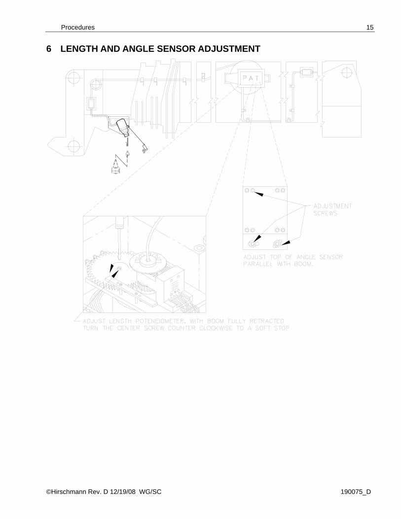
3 BASIC ADJUSTMENT OF THE HARDWARE Length: Ensure that the length cable tension is correct with fully retracted boom by turning the cable reel 2 to check that the reel fully retracts. Then remove cover from cable reel and adjust the potentiometer till fully counter clockwise to the soft stop. Angle: Set the boom to 0 degrees and set a digital level on the boom. Adjust the angle sensor to the same angle as the boom. Check the angle at 20 degrees, 45 degrees, 70 degrees. Angle display should be less than ± .2 degrees of the value of the inclinometer. Pressure Channel: Rest the boom and disconnect the pressure transducers. Measure the voltage of both pressure transducers on the terminal board. The output voltage of the pressure transducers should be 4.00ma. Check the function of the hoist limit switch (anti-two-block) Check function of lever lockout. Measure and record the power supply voltages.
Service Manual PRS145
©Hirschmann Rev. D 12/19/08 WG/SC 190075_D
4
4 DEFINITIONS BOOM LENGTH The straight line thru the centerline of boom pivot pin to the centerline of the boom point load hoist sheave pin measured along the longitudinal axis of the boom. (Indicator ± 2%) BOOM ANGLE The angle between the longitudinal centerline of the boom base section and the horizontal plane. (Indicator 65° to 90° boom angle + 0°/2°; less than 65° boom angle + 0°/-3°) RADIUS OF LOAD The horizontal distance from a vertical projection of the crane’s axis of rotation to the supporting surface, before loading, to the center of the vertical hoist line or tackle with rated load applied. (Indicator 100% to 110%) RATED LOAD The load value shown on the applicable load ratings chart of the crane for the particular crane configuration, boom length, boom angle, or functions or these variables. For radii outside those shown on the load ratings chart, the rated load is to be considered as zero. ACTUAL LOAD The weight of the load being lifted and all additional equipment such as blocks, slings, sensors, etc. Also referred to as working load. (Indicator 100% to 110%) CRANE CONFIGURATION The physical arrangement of the crane as prepared for a particular operation in conformance with the manufacturer’s operating instructions and load rating chart. TWO-BLOCKING Contact of the lower load block or hook with the upper load block, boom point, or boom point machinery. ANALOGUE Electrical signals that vary in proportion to the quantities they represent. (Boom length, angle, and pressure transducer) DIGITAL Electrical signals of an on-and-off-state (two different voltage levels) to represent some quantity of operation. (A2B, area definition switch)
Drawings
©Hirschmann Rev. D 12/19/08 WG/SC 190075_D
5
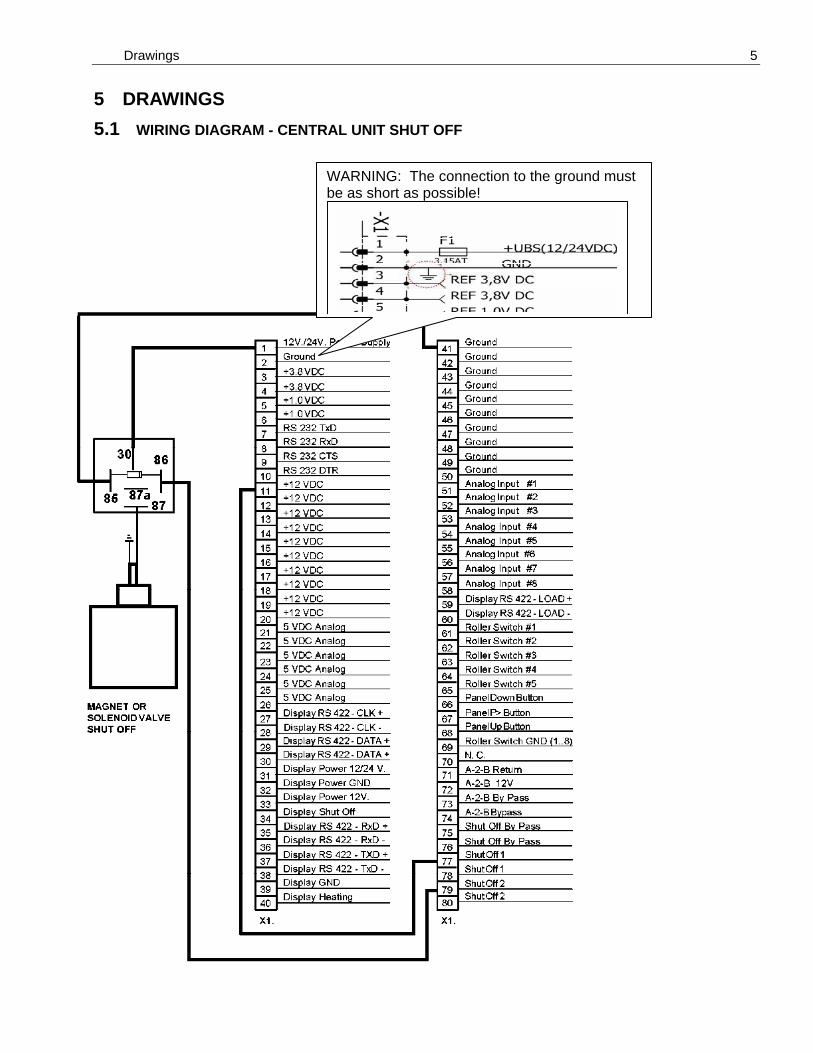
5 DRAWINGS 5.1 WIRING DIAGRAM - CENTRAL UNIT SHUT OFF
WARNING: The connection to the ground must be as short as possible!
Service Manual MARK4E/2
©Hirschmann Rev. D 12/19/08 WG/SC 190075_D
6
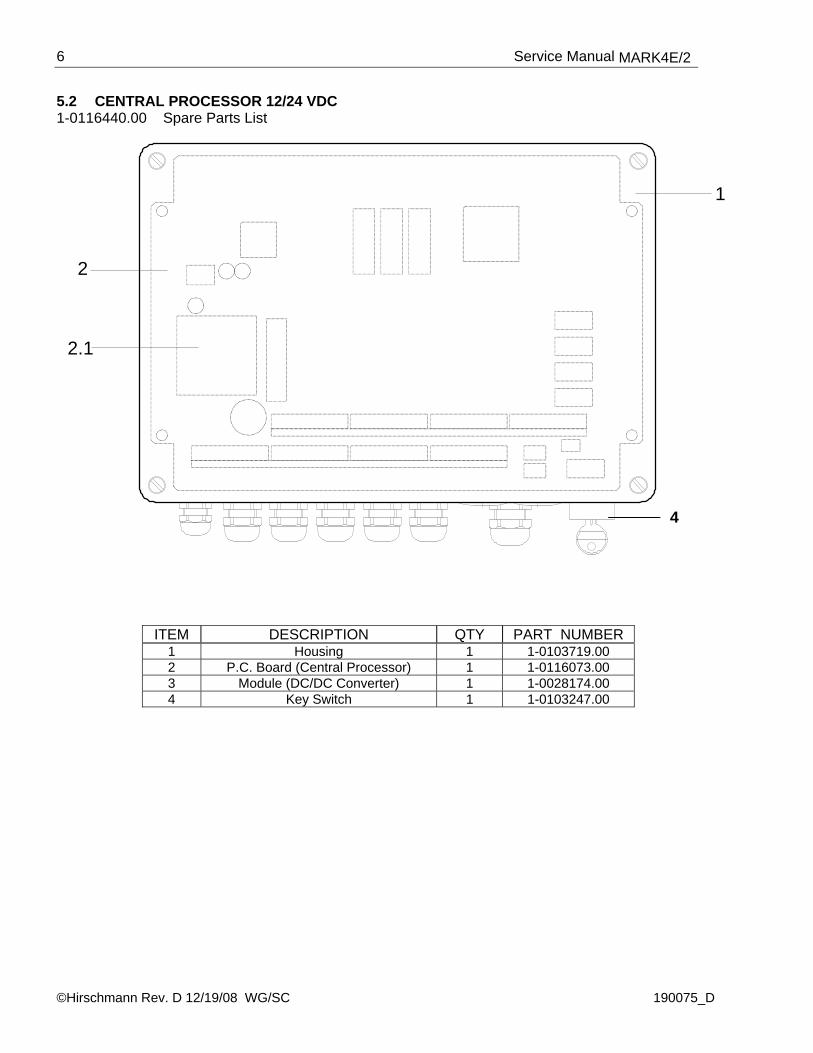
5.2 CENTRAL PROCESSOR 12/24 VDC 1-0116440.00 Spare Parts List
2.1
2
1
ITEM DESCRIPTION QTY PART NUMBER 1 Housing 1 1-0103719.00 2 P.C. Board (Central Processor) 1 1-0116073.00 3 Module (DC/DC Converter) 1 1-0028174.00 4 Key Switch 1 1-0103247.00
4

Drawings
©Hirschmann Rev. D 12/19/08 WG/SC 190075_D
7
5.3 ELECTRICAL DIAGRAM – CENTRAL UNIT/CONSOLE
Service Manual MARK4E/2
©Hirschmann Rev. D 12/19/08 WG/SC 190075_D
8
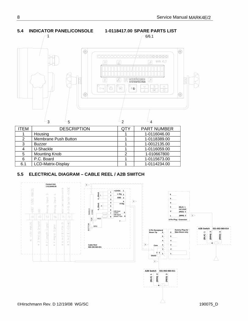
5.4 INDICATOR PANEL/CONSOLE 1-0118417.00 SPARE PARTS LIST
3 5
1
2 4
SYSTEMTECHNIK
6/6.1
ITEM DESCRIPTION QTY PART NUMBER
1 Housing 1 1-0116046.00 2 Membrane Push Button 1 1-0118389.00 3 Buzzer 1 1-0012135.00 4 U-Shackle 1 1-0116059.00 5 Mounting Knob 2 1-010667800 6 P.C. Board 1 1-0115673.00
6.1 LCD-Matrix-Display 1 1-0114234.00 5.5 ELECTRICAL DIAGRAM – CABLE REEL / A2B SWITCH
(BLK) 1
031-002-060-014
(BLK
) 1
not used(RED) 3
(BRN) 21
2
3
4
5
6
(BR
N)
2
(RED
) 3
6 Pin Plug - Extension
A2B SwitchDummy Plug for Main Boom only
2
1
3
5
4
6
3
1
2
6
4
5
6 Pin ReceptacalBoom Tip
A2B Switch
(RED
) 3
(BR
N)
2
(BLK
) 1
031-002-060-011
TOP
BRN
BO
TTO
M
CO
RE
RED
SH
IELD
2
2
L
A
Cable Reel068-308-060-001
1
2
3
4
6
5
7
1
2
3
6
5
4
8
7
+12VDC
L-Sig.
GND
A-Sig.
A2B Power+12VDC A2B Signal-closed = +12V
1
4...2
0mA
4...2
0mA
23Shield
Core
1
1
Central Unit1-0116440.00

Drawings
©Hirschmann Rev. D 12/19/08 WG/SC 190075_D
9
5.6 CABLE REEL PARTS LIST
6
6
8
10
3 1
11
2
7
4
5
9
6
Service Manual MARK4E/2
©Hirschmann Rev. D 12/19/08 WG/SC 190075_D
10
DRAWING 5.5 CABLE REEL - PARTS LIST - continued
CABLE REEL ASSEMBLY, PARTS LIST PART NO. PAT 068-308-060-001
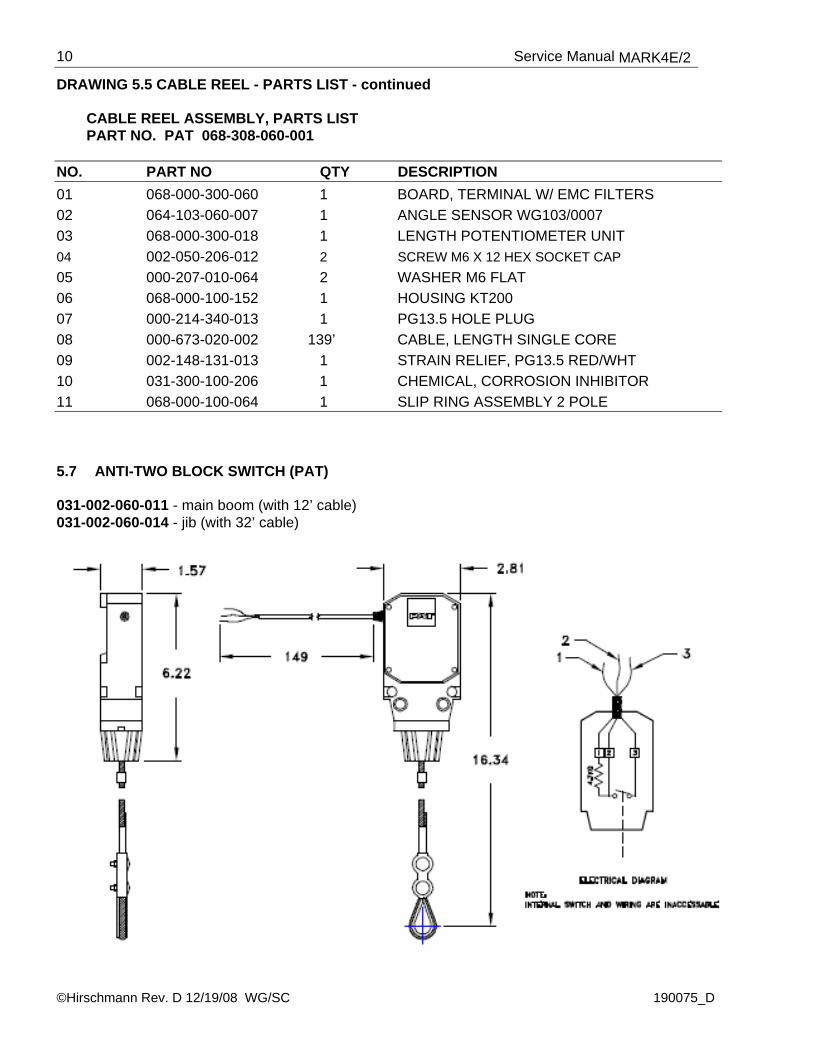
NO. PART NO QTY DESCRIPTION 01 068-000-300-060 1 BOARD, TERMINAL W/ EMC FILTERS 02 064-103-060-007 1 ANGLE SENSOR WG103/0007 03 068-000-300-018 1 LENGTH POTENTIOMETER UNIT 04 002-050-206-012 2 SCREW M6 X 12 HEX SOCKET CAP 05 000-207-010-064 2 WASHER M6 FLAT 06 068-000-100-152 1 HOUSING KT200 07 000-214-340-013 1 PG13.5 HOLE PLUG 08 000-673-020-002 139’ CABLE, LENGTH SINGLE CORE 09 002-148-131-013 1 STRAIN RELIEF, PG13.5 RED/WHT 10 031-300-100-206 1 CHEMICAL, CORROSION INHIBITOR 11 068-000-100-064 1 SLIP RING ASSEMBLY 2 POLE 5.7 ANTI-TWO BLOCK SWITCH (PAT) 031-002-060-011 - main boom (with 12’ cable) 031-002-060-014 - jib (with 32’ cable)
Drawings
©Hirschmann Rev. D 12/19/08 WG/SC 190075_D
11
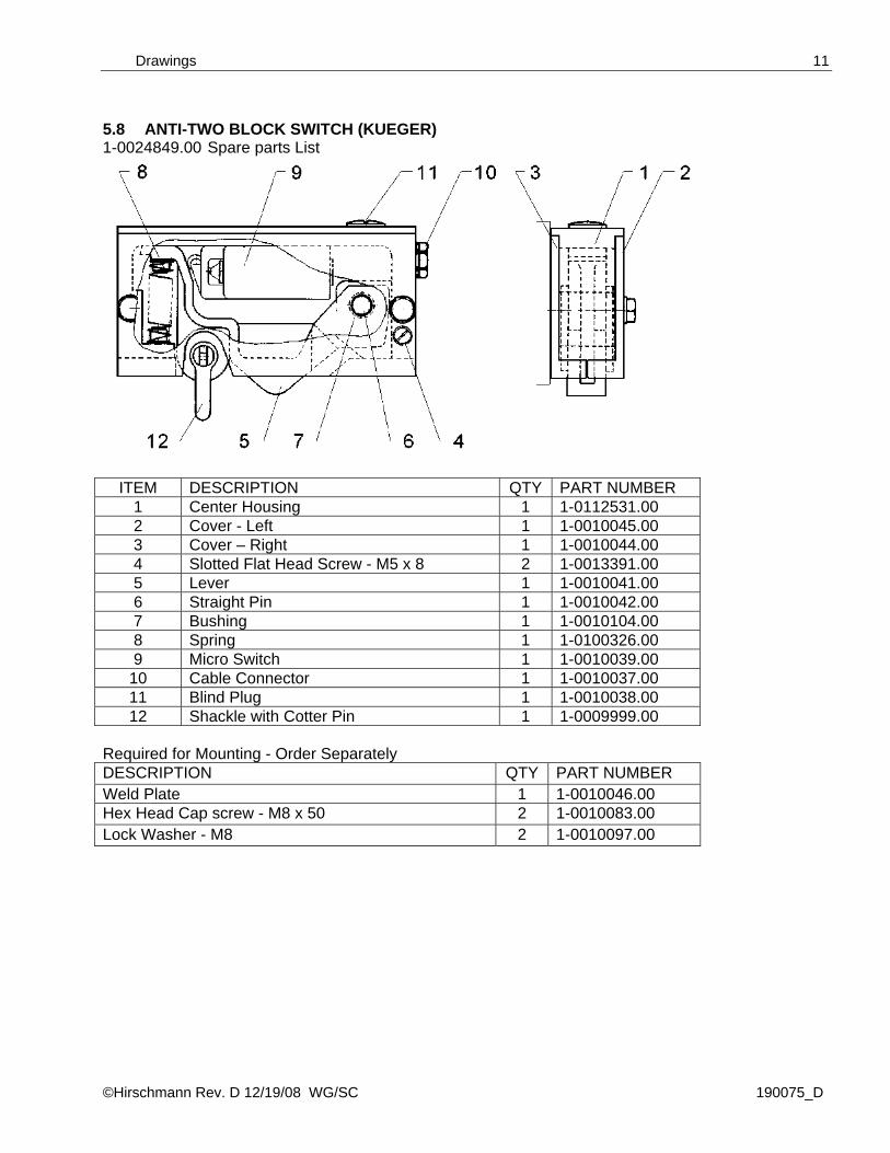
5.8 ANTI-TWO BLOCK SWITCH (KUEGER) 1-0024849.00 Spare parts List
ITEM DESCRIPTION QTY PART NUMBER 1 Center Housing 1 1-0112531.00 2 Cover - Left 1 1-0010045.00 3 Cover – Right 1 1-0010044.00 4 Slotted Flat Head Screw - M5 x 8 2 1-0013391.00 5 Lever 1 1-0010041.00 6 Straight Pin 1 1-0010042.00 7 Bushing 1 1-0010104.00 8 Spring 1 1-0100326.00 9 Micro Switch 1 1-0010039.00
10 Cable Connector 1 1-0010037.00 11 Blind Plug 1 1-0010038.00 12 Shackle with Cotter Pin 1 1-0009999.00
Required for Mounting - Order Separately DESCRIPTION QTY PART NUMBER Weld Plate 1 1-0010046.00 Hex Head Cap screw - M8 x 50 2 1-0010083.00 Lock Washer - M8 2 1-0010097.00
Service Manual MARK4E/2
©Hirschmann Rev. D 12/19/08 WG/SC 190075_D
12
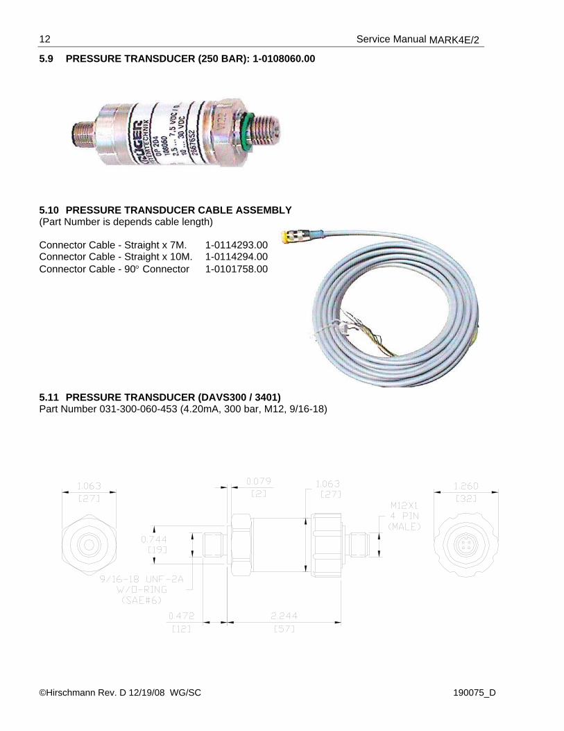
5.9 PRESSURE TRANSDUCER (250 BAR): 1-0108060.00 5.10 PRESSURE TRANSDUCER CABLE ASSEMBLY (Part Number is depends cable length) Connector Cable - Straight x 7M. 1-0114293.00 Connector Cable - Straight x 10M. 1-0114294.00 Connector Cable - 90° Connector 1-0101758.00 5.11 PRESSURE TRANSDUCER (DAVS300 / 3401) Part Number 031-300-060-453 (4.20mA, 300 bar, M12, 9/16-18)

Drawings
©Hirschmann Rev. D 12/19/08 WG/SC 190075_D
13
Anal
og In
put 2
Anal
og In
put 1
GN
D
GN
D3
- BLK
(Pi
ston
Tra
ns.)
3 - B
LK (
Rod
Tra
ns.)
41 42
2 - B
LU (P
isto
n S
igna
l)
51
2 - B
LU (
Rod
Sig
nal)
52
GN
D
+12
VDC
GN
D
X1.
+UD
C
1 2 3 4 5 6
1 - B
RN
(Pis
ton.
)
1 - B
RN
(Rod
)
+12V
DC
117 8 109
+12V
DC
12
(+24
VD
C)
C rane Voltage-refer to Crane DW G.-
MARK4 E/2 CENTRAL UNIT
Piston Pressure Transducer 300bar
031-300-060-452
Cable assembly 031-300-060-693
Cable assembly 031-300-060-693
Rod Pressure Transducer 300bar
031-300-060-452
3 SS
3 SS
not u
sed
Sign
al
4...2
0 m
A
+12
VDC
42
- BLU
1 - B
RN
1
3 - B
LK
23G
ND
not u
sed
Sign
al
4...2
0 m
A
+12
VDC
42
- BLU
1 - B
RN
1
3 - B
LK
23G
ND
5.12 CABLE ASSEMBLY (PRESSURE TRANS), 031-300-060-693
Pressure Transducer and Cable Assembly connection in Central Unit:
Service Manual MARK4E/2
©Hirschmann Rev. D 12/19/08 WG/SC 190075_D
14
Central Unit1-0116440.00
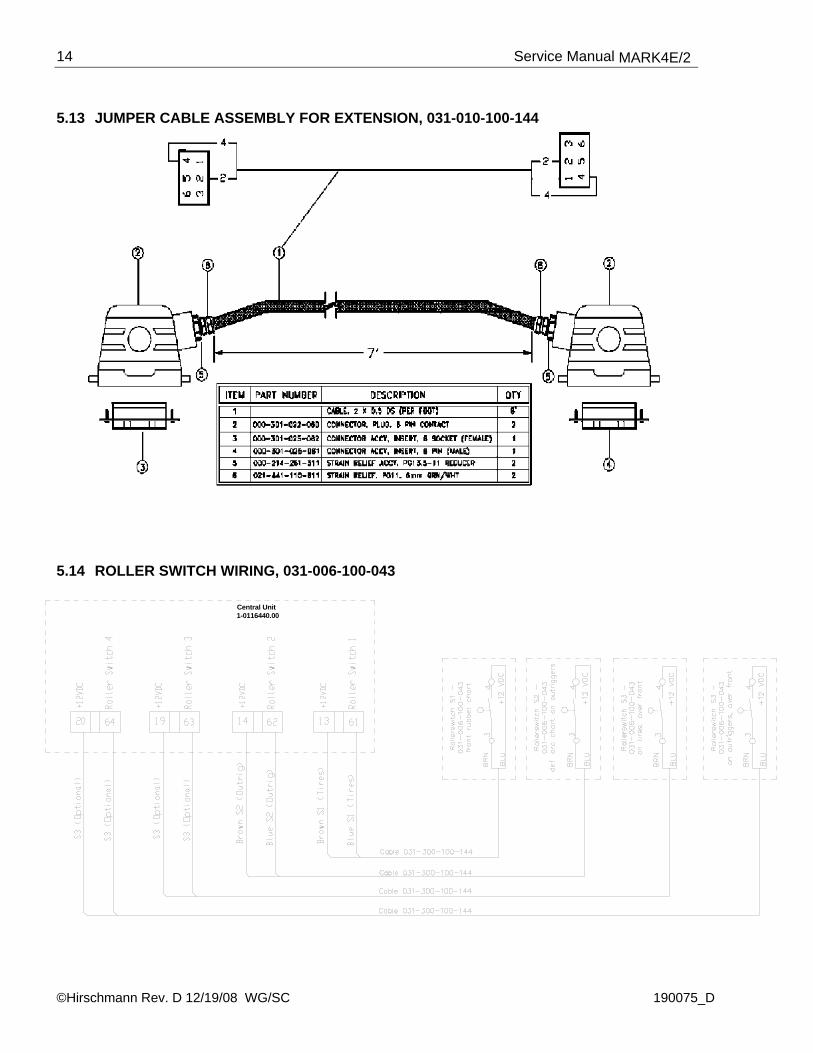
5.13 JUMPER CABLE ASSEMBLY FOR EXTENSION, 031-010-100-144 5.14 ROLLER SWITCH WIRING, 031-006-100-043
Procedures
©Hirschmann Rev. D 12/19/08 WG/SC 190075_D
15
6 LENGTH AND ANGLE SENSOR ADJUSTMENT

Service Manual MARK4E/2
©Hirschmann Rev. D 12/19/08 WG/SC 190075_D
16
6.1 EPROM REPLACEMENT IN CENTRAL UNIT
1. Loosen screws and remove electronic box cover.
2. With power off to the system use small screwdriver to lift I.C. out of socket.
3. Replace I.C. with notch down and flat side to the top as shown in diagram. WARNING: If I. C. is placed in wrong, the I.C. will be destroyed and a new I.C. will have to be ordered.
Procedures
©Hirschmann Rev. D 12/19/08 WG/SC 190075_D
17
6.2 PISTON & ROD PRESSURE CHANNEL ADJUSTMENT 6.2.1 Adjust pressure piston: 1. Turn power off to the system and wire simulator to the piston pressure channel (blue to term. # 12,
brown to term. #45, green/yellow to term. # 51). Put voltmeter ground on term. # 45 and positive to term. # 51.
2. Go to the Calibration menu by pushing the up then P button while in the Program menu screen. 3. Push up or down button until NORM menu title is blinking, then push P button. 4. Push up or down button until PRESSURE-PIS menu title is blinking, then push P button. 5. Adjust simulator to 4.00 ma. 6. Push up or down button until MINIMUM menu title is blinking, then push P button. 7. Push P button until all digits have been verified with the proper value, which will be 000.00 bar. 8. Adjust simulator to 20.00 ma. Push up or down button until MAXIMUM menu title is blinking, then
push P button. 9. Push P button until all digits have been verified with the proper value, which will be 300.00 bar. 10. Push up or down button until ADJUST menu title is blinking then push P button. 11. Push down button until EXIT menu title is blinking then push P button. 6.2.2 Adjust pressure Rod: 12. Move positive lead of voltmeter to term. # 52. 13. Push up or down button until PRESSURE-ROD menu title is blinking then push P button. 14. Adjust simulator to 4.00 ma. 15. Push up or down button until MINIMUM menu title is blinking then push P button. 16. Push P button until all digits have been verified with the proper value, which will be 000.00 bar. 17. Adjust simulator to 20.00ma 18. .Push up or down button until MAXIMUM menu title is blinking then push P button. 19. Push P button until all digits have been verified with the proper value, which will be 300.00 bar. 20. Push up or down button until ADJUST menu title is blinking then push P button. 21. Push down button until EXIT menu title is blinking then push P button. 22. Push down button to EXIT then P button until you get to the Program menu and enter the working
display.
Service Manual MARK4E/2
©Hirschmann Rev. D 12/19/08 WG/SC 190075_D
18
6.3 LENGTH CABLE REPLACEMENT PROBLEM: Damaged or broken length cable. Replace length cable using the following procedure: 1. Turn drum counter-clock wise until drum is fully tensioned. 2. Tighten locking nuts to drum to prevent recoil. Refer to Drawing 1 in Section 11 – Appendix. 3. Take reel cover off and remove screw and cable clamp. 4. Remove wire from slip ring disc cut wire ends off and remove all old length cable from reel. 5. Feed new length cable through drum. Strip wire, separate inner core from shield, insulate shield
by using heat shrink or electrical tape, put spade lugs on and wire to slip ring disc terminals 2 and 3. Put cable clamp on and tighten screw to drum.
6. Put silicone around hole where the new length cable is fed through the drum. 7. While holding cable or drum, (Warning! To prevent recoil.) loosen locking nuts and jam the nuts
together. 8. Slowly allow cable to spool onto the drum, keeping the cable tight together and layering properly,
spool until all tension is off the cable reel. 9. Re string cable through the roller guides and reconnect at the boom tip. 10. After cable replacement refer to length adjustment procedure to reset length. 11. Put cover on reel. Crane is ready to put back into service.

Troubleshooting Flow Charts
©Hirschmann Rev. D 12/19/08 WG/SC 190075_D
19
7 TROUBLESHOOTING FLOW CHARTS 7.1 GENERAL FLOWCHART This section explains how to handle a problem that may arise with the PAT Load Moment Indicator Kruger Mark 4E/2 System. The procedures are easy to follow and are given in flowcharts on the following pages. Start with the general flowchart below that will guide you to one of the other detailed flowcharts shown in this section.
Go to Section 7.2
What’s Wrong?
START
Lever Lockout Activated
Go to Section 7.3 Blank Display
Go to Section 7.4 Anti-Two Block Problem
Go to Section 7.5 Length Reading Problem
Go to Section 7.6 Angle Reading Problem
Service Manual MARK4E/2
©Hirschmann Rev. D 12/19/08 WG/SC 190075_D
20
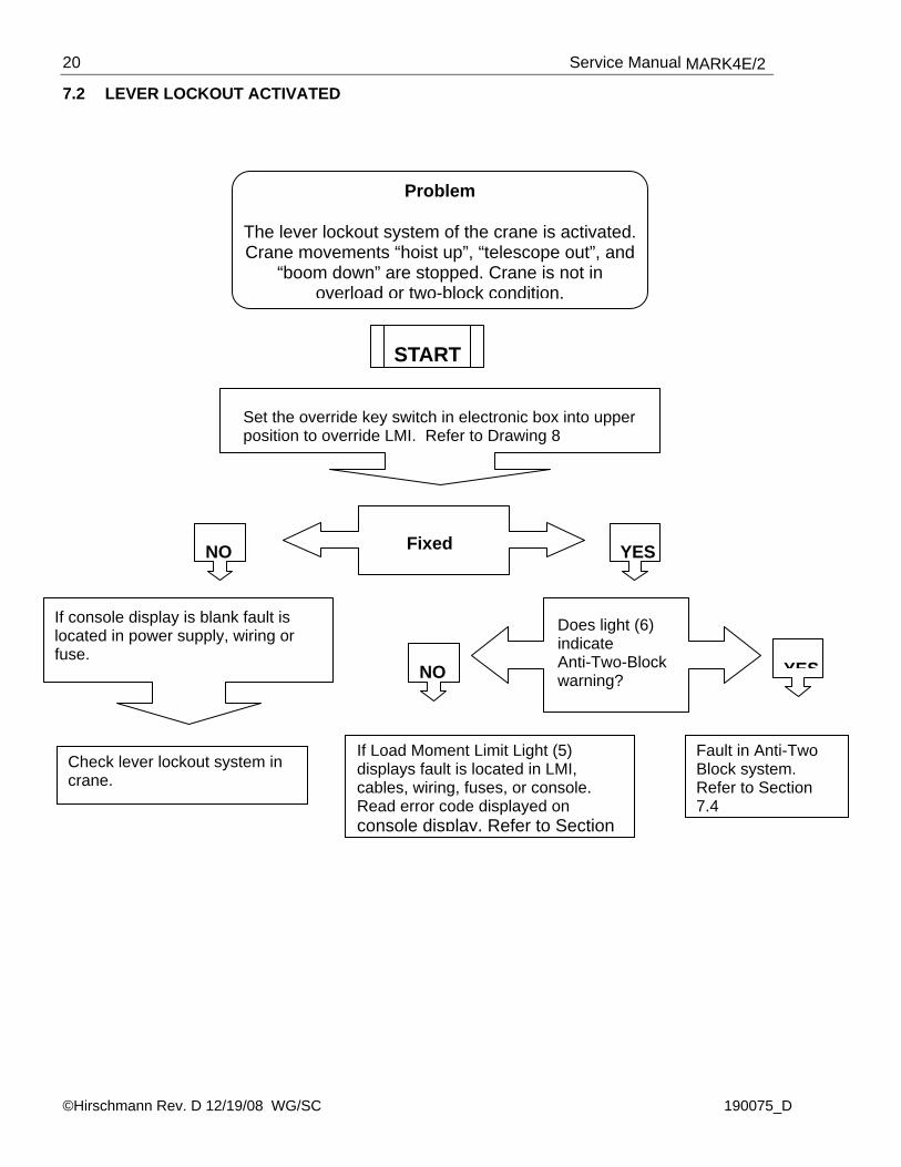
7.2 LEVER LOCKOUT ACTIVATED
Problem
The lever lockout system of the crane is activated. Crane movements “hoist up”, “telescope out”, and
“boom down” are stopped. Crane is not in overload or two-block condition.
START
Set the override key switch in electronic box into upper position to override LMI. Refer to Drawing 8
NO Fixed YES
If console display is blank fault is located in power supply, wiring or fuse.
Does light (6) indicate Anti-Two-Block warning?
Check lever lockout system in crane.
If Load Moment Limit Light (5) displays fault is located in LMI, cables, wiring, fuses, or console. Read error code displayed on console display. Refer to Section
NO YES
Fault in Anti-Two Block system. Refer to Section 7.4
Troubleshooting Flow Charts
©Hirschmann Rev. D 12/19/08 WG/SC 190075_D
21
7.3 BLANK DISPLAY
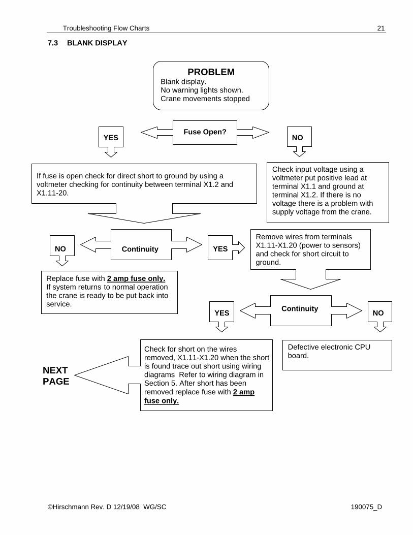
Remove wires from terminals X1.11-X1.20 (power to sensors) and check for short circuit to ground.
Check for short on the wires removed, X1.11-X1.20 when the short is found trace out short using wiring diagrams Refer to wiring diagram in Section 5. After short has been removed replace fuse with 2 amp fuse only.
If fuse is open check for direct short to ground by using a voltmeter checking for continuity between terminal X1.2 and X1.11-20.
Check input voltage using a voltmeter put positive lead at terminal X1.1 and ground at terminal X1.2. If there is no voltage there is a problem with supply voltage from the crane.
Continuity
Replace fuse with 2 amp fuse only. If system returns to normal operation the crane is ready to be put back into service.
NO YES
PROBLEM Blank display. No warning lights shown. Crane movements stopped
Fuse Open? YES NO
Defective electronic CPU board.
NEXT PAGE
Continuity YES NO

Service Manual MARK4E/2
©Hirschmann Rev. D 12/19/08 WG/SC 190075_D
22
PREVIOUS PAGE
Then check output voltage to console using a voltmeter put positive lead at terminal X1.33 and ground at terminal X1.2.
Voltage?
Replace console. Replace or repair Electronic box CPU.
If system returns to normal operation the crane is ready to be put back in service.
NO Display working? YES
YES NO
Troubleshooting Flow Charts
©Hirschmann Rev. D 12/19/08 WG/SC 190075_D
23
7.4 ANTI-TWO-BLOCK PROBLEM
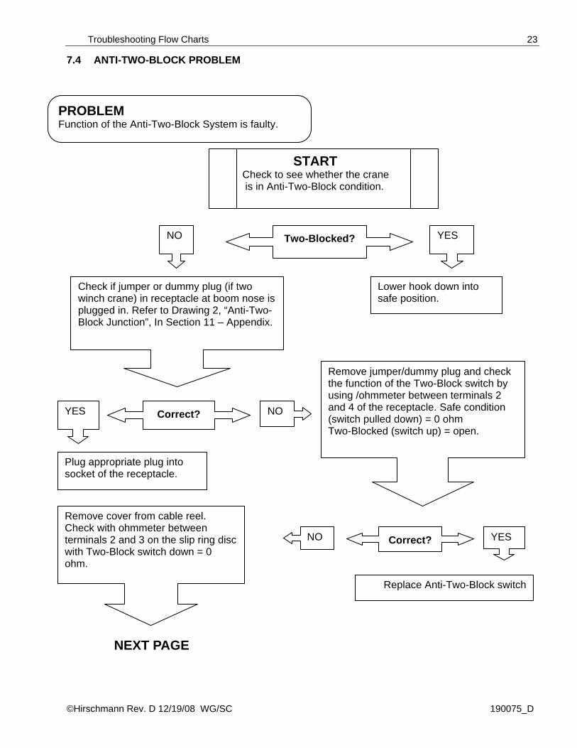
PROBLEM Function of the Anti-Two-Block System is faulty.
START Check to see whether the crane is in Anti-Two-Block condition.
Two-Blocked?
Lower hook down into safe position.
Check if jumper or dummy plug (if two winch crane) in receptacle at boom nose is plugged in. Refer to Drawing 2, “Anti-Two-Block Junction”, In Section 11 – Appendix.
Plug appropriate plug into socket of the receptacle.
Remove jumper/dummy plug and check the function of the Two-Block switch by using /ohmmeter between terminals 2 and 4 of the receptacle. Safe condition (switch pulled down) = 0 ohm Two-Blocked (switch up) = open.
Replace Anti-Two-Block switch
NEXT PAGE
Remove cover from cable reel. Check with ohmmeter between terminals 2 and 3 on the slip ring disc with Two-Block switch down = 0 ohm.
Correct?
NO YES
YES NO
YES NO
Correct?
Service Manual MARK4E/2
©Hirschmann Rev. D 12/19/08 WG/SC 190075_D
24
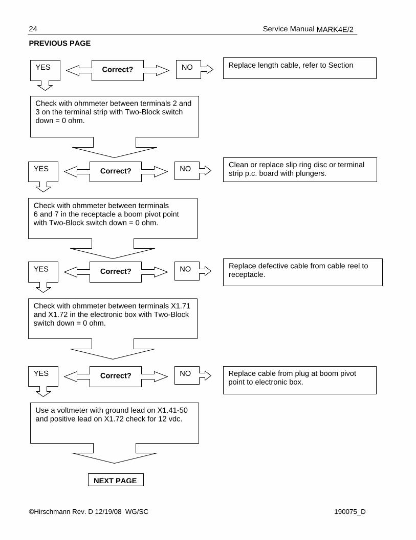
PREVIOUS PAGE
Clean or replace slip ring disc or terminal strip p.c. board with plungers.
Replace defective cable from cable reel to receptacle.
Replace cable from plug at boom pivot point to electronic box.
Check with ohmmeter between terminals 6 and 7 in the receptacle a boom pivot point with Two-Block switch down = 0 ohm.
YES NO Correct?
Check with ohmmeter between terminals 2 and 3 on the terminal strip with Two-Block switch down = 0 ohm.
YES NO Correct? Replace length cable, refer to Section
YES NO Correct?
Check with ohmmeter between terminals X1.71 and X1.72 in the electronic box with Two-Block switch down = 0 ohm.
YES NO Correct?
Use a voltmeter with ground lead on X1.41-50 and positive lead on X1.72 check for 12 vdc.
NEXT PAGE
Troubleshooting Flow Charts
©Hirschmann Rev. D 12/19/08 WG/SC 190075_D
25
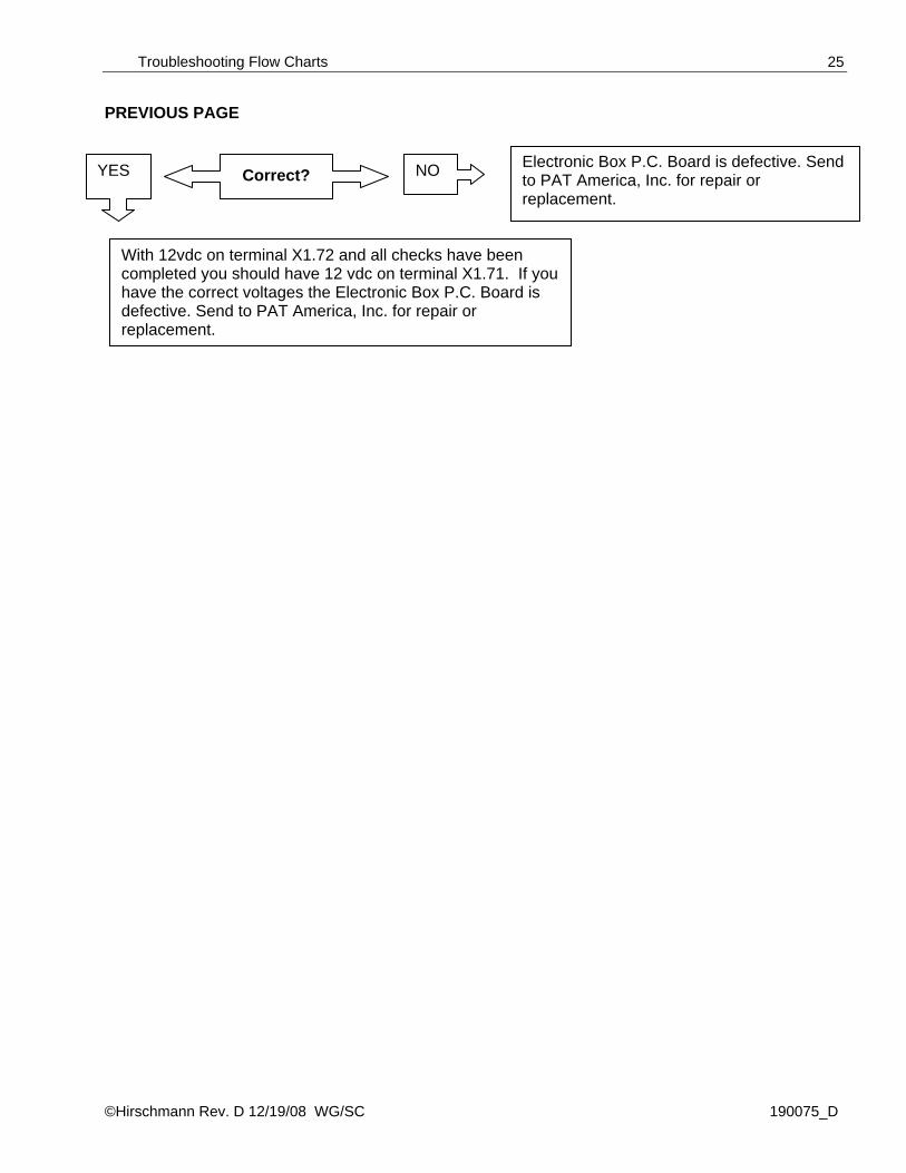
PREVIOUS PAGE
With 12vdc on terminal X1.72 and all checks have been completed you should have 12 vdc on terminal X1.71. If you have the correct voltages the Electronic Box P.C. Board is defective. Send to PAT America, Inc. for repair or replacement.
Electronic Box P.C. Board is defective. Send to PAT America, Inc. for repair or replacement.
YES NO Correct?

Service Manual MARK4E/2
©Hirschmann Rev. D 12/19/08 WG/SC 190075_D
26
7.5 LENGTH READING PROBLEM
If indication is off by approximately 3 ft. (1m) add or remove 1 rap from cable reel. If this does not repair problem refer to Length Adjustment Procedure section?
If indication is correct at short boom and has bad indication the problem my be a defective length potentiometer. Refer to Section?
START Check mechanical adjustment of the length Potentiometer with boom fully retracted
Correct? NO YES
PROBLEM Length reading is incorrect. Crane Is not “out of load chart” condition?
Troubleshooting Flow Charts
©Hirschmann Rev. D 12/19/08 WG/SC 190075_D
27
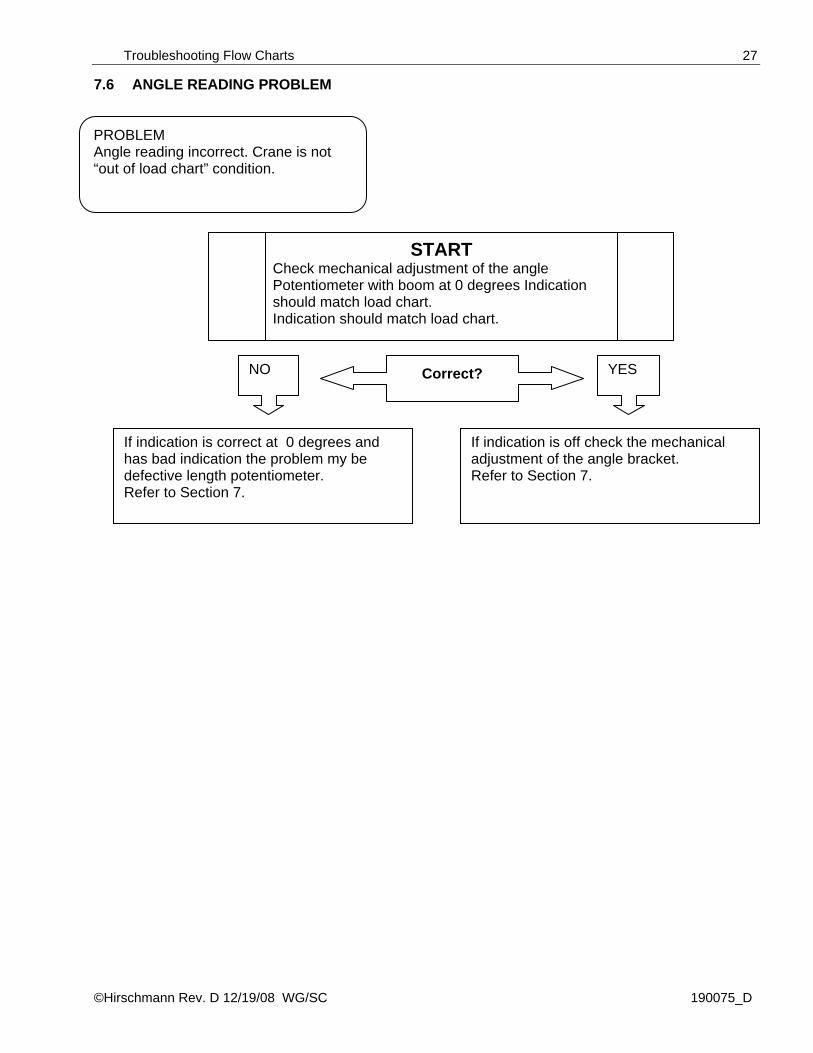
7.6 ANGLE READING PROBLEM
If indication is off check the mechanical adjustment of the angle bracket. Refer to Section 7.
If indication is correct at 0 degrees and has bad indication the problem my be defective length potentiometer. Refer to Section 7.
START Check mechanical adjustment of the angle Potentiometer with boom at 0 degrees Indication should match load chart. Indication should match load chart.
Correct? NO YES
PROBLEM Angle reading incorrect. Crane is not “out of load chart” condition.

Service Manual MARK4E/2
©Hirschmann Rev. D 12/19/08 WG/SC 190075_D
28
8 ERROR CODES 8.1 OPERATOR ERROR CODE TABLE Operation errors are measurement errors, i.e.; the actual radius is lower than in the load chart. The information will be shown on the second line of the display with an error message or description. The error will be automatically reset when user corrects error. ERROR DISPLAYED
ERROR CAUSE ACTION
A2B CONDITION Anti-2-Block circuit has been activated.
The hoist limit switch has been activated or open in A-2-B circuit.
Lower the hook. Check all cables and connection to hoist limit switch.
A2B BYPASS The hoist limit switch has been by-passed.
The hoist limit by-pass button has been pushed or is defective.
Error occurs when bypass button on the panel is pushed.
LOAD > MAX LOAD
The actual load is greater than the max load.
The crane is at maximum lifting capacity.
Lower load or move load into safe working condition.
SHUT OFF BYPASS
The shut-off system is currently by-passed.
The shut-off contact has been by-passed by the user with the aid of the key operated switch installed on the electronic box.
Remove key from electronic box.
LENGTH < CHART The length of the main boom is shorter than the lowest value in the Load Chart for the configuration selected.
The incorrect configuration has been selected. The length indication is incorrect.
Select proper configuration. Check length indication with boom fully retracted, if incorrect length is indicated Refer to Section 7.5
LENGTH > CHART The length of the main boom is longer than the highest value in the Load Chart for the configuration selected.
The incorrect configuration has been selected. The length indication is incorrect.
Select proper configuration. Check length indication with boom fully extended, if incorrect length is indicated Refer to Section 7.5.
RADIUS < CHART The Radius is shorter than the lowest value in the Load Chart for the configuration selected.
The crane has exceeded the shortest radius for the configuration that has been selected.
Lower or extend boom to return to a working radius in the load chart. Check radius indication to actual radius.
RADIUS > CHART The Radius is longer than the highest value in the Load Chart for the configuration selected.
The crane has exceeded the longest radius for the configuration that has been selected.
Raise or retract boom to return to a working radius in the load chart. Check radius indication to actual radius.
Error Codes
©Hirschmann Rev. D 12/19/08 WG/SC 190075_D
29
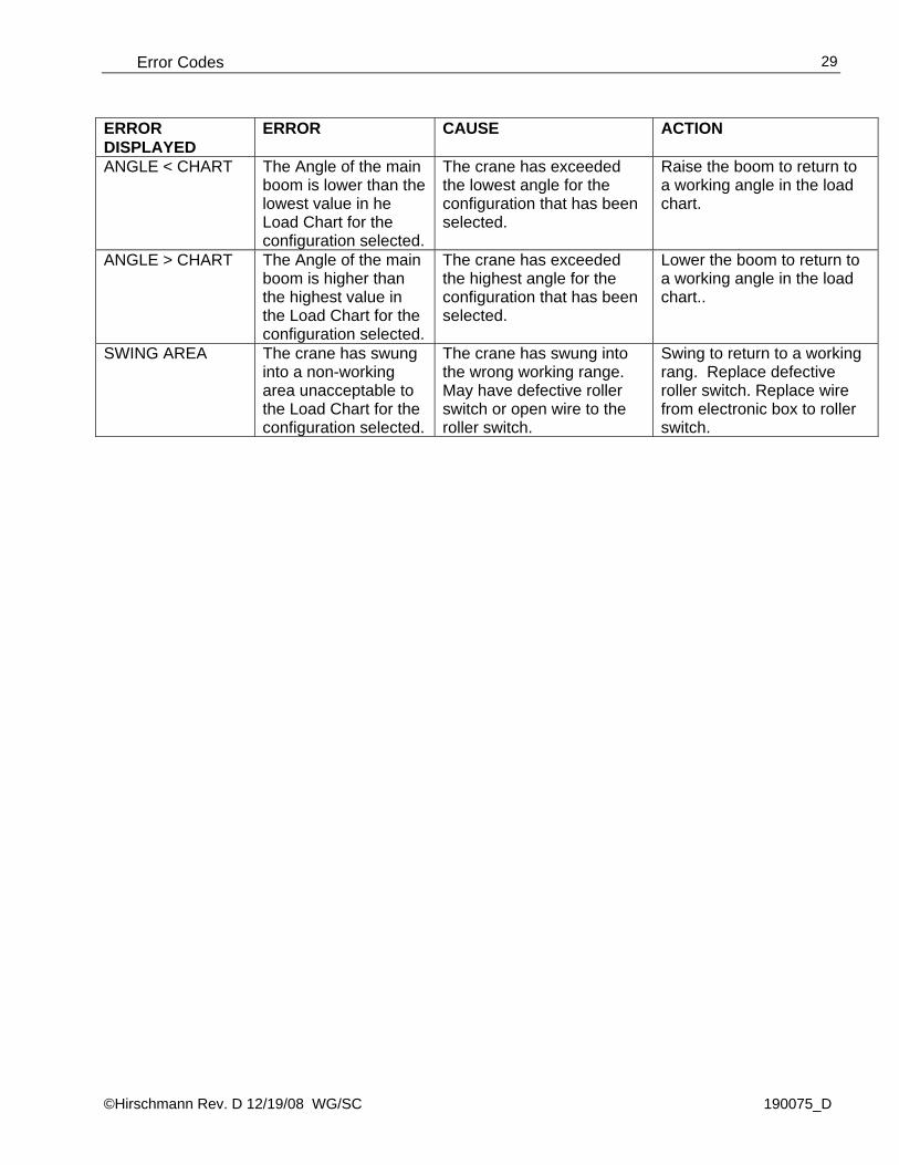
ERROR DISPLAYED
ERROR CAUSE ACTION
ANGLE < CHART The Angle of the main boom is lower than the lowest value in he Load Chart for the configuration selected.
The crane has exceeded the lowest angle for the configuration that has been selected.
Raise the boom to return to a working angle in the load chart.
ANGLE > CHART The Angle of the main boom is higher than the highest value in the Load Chart for the configuration selected.
The crane has exceeded the highest angle for the configuration that has been selected.
Lower the boom to return to a working angle in the load chart..
SWING AREA The crane has swung into a non-working area unacceptable to the Load Chart for the configuration selected.
The crane has swung into the wrong working range. May have defective roller switch or open wire to the roller switch.
Swing to return to a working rang. Replace defective roller switch. Replace wire from electronic box to roller switch.
Service Manual MARK4E/2
©Hirschmann Rev. D 12/19/08 WG/SC 190075_D
30
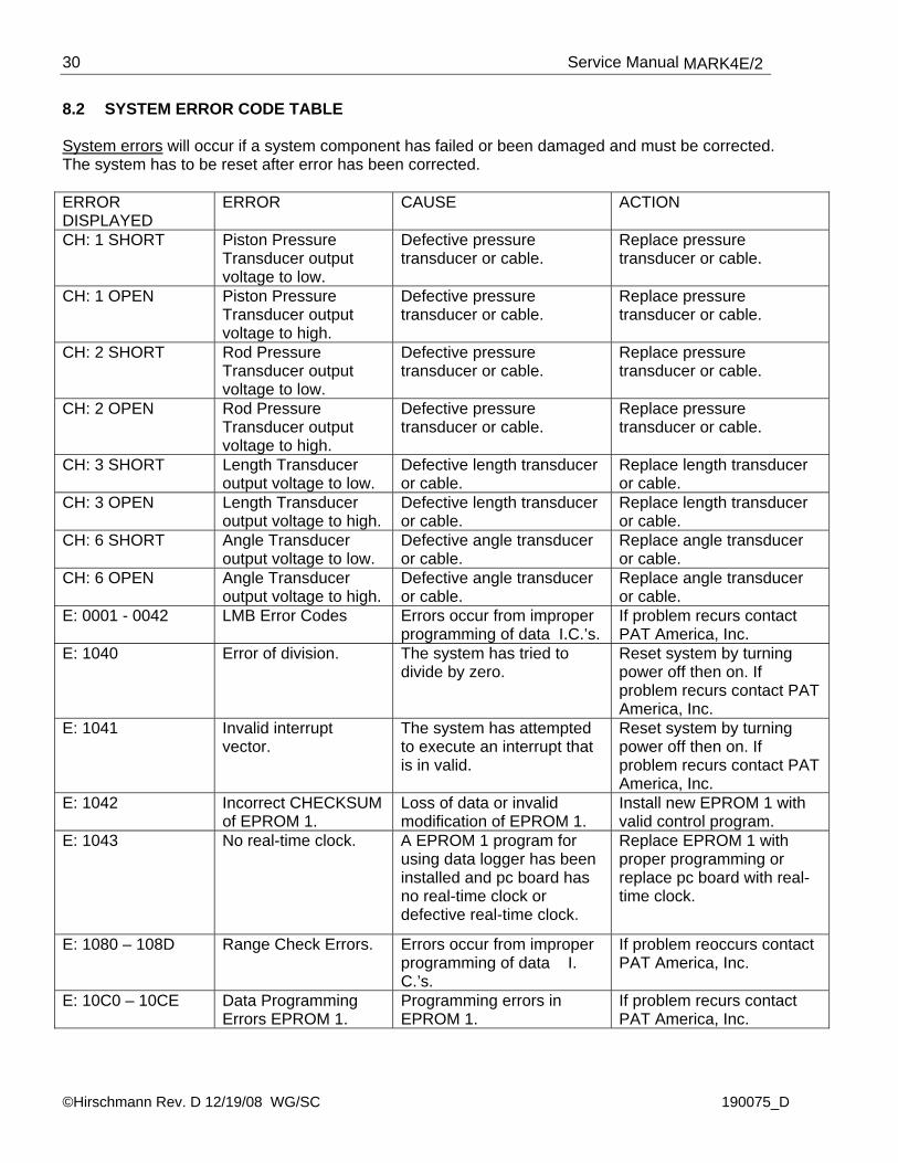
8.2 SYSTEM ERROR CODE TABLE System errors will occur if a system component has failed or been damaged and must be corrected. The system has to be reset after error has been corrected. ERROR DISPLAYED
ERROR CAUSE ACTION
CH: 1 SHORT Piston Pressure Transducer output voltage to low.
Defective pressure transducer or cable.
Replace pressure transducer or cable.
CH: 1 OPEN Piston Pressure Transducer output voltage to high.
Defective pressure transducer or cable.
Replace pressure transducer or cable.
CH: 2 SHORT Rod Pressure Transducer output voltage to low.
Defective pressure transducer or cable.
Replace pressure transducer or cable.
CH: 2 OPEN Rod Pressure Transducer output voltage to high.
Defective pressure transducer or cable.
Replace pressure transducer or cable.
CH: 3 SHORT Length Transducer output voltage to low.
Defective length transducer or cable.
Replace length transducer or cable.
CH: 3 OPEN Length Transducer output voltage to high.
Defective length transducer or cable.
Replace length transducer or cable.
CH: 6 SHORT Angle Transducer output voltage to low.
Defective angle transducer or cable.
Replace angle transducer or cable.
CH: 6 OPEN Angle Transducer output voltage to high.
Defective angle transducer or cable.
Replace angle transducer or cable.
E: 0001 - 0042 LMB Error Codes Errors occur from improper programming of data I.C.’s.
If problem recurs contact PAT America, Inc.
E: 1040 Error of division. The system has tried to divide by zero.
Reset system by turning power off then on. If problem recurs contact PAT America, Inc.
E: 1041 Invalid interrupt vector.
The system has attempted to execute an interrupt that is in valid.
Reset system by turning power off then on. If problem recurs contact PAT America, Inc.
E: 1042 Incorrect CHECKSUM of EPROM 1.
Loss of data or invalid modification of EPROM 1.
Install new EPROM 1 with valid control program.
E: 1043 No real-time clock. A EPROM 1 program for using data logger has been installed and pc board has no real-time clock or defective real-time clock.
Replace EPROM 1 with proper programming or replace pc board with real-time clock.
E: 1080 – 108D Range Check Errors. Errors occur from improper programming of data I. C.’s.
If problem reoccurs contact PAT America, Inc.
E: 10C0 – 10CE Data Programming Errors EPROM 1.
Programming errors in EPROM 1.
If problem recurs contact PAT America, Inc.

Error Codes
©Hirschmann Rev. D 12/19/08 WG/SC 190075_D
31
ERROR DISPLAYED
ERROR CAUSE ACTION
E: 1100 Invalid EEPROM identification.
Incorrect EEPROM inserted in EEPROM 2 slot.
Replace the EEPROM with valid programming.
E: 1101 Incorrect “CHECKSUM” EEPROM (EPROM2)
Information has been changed in EPROM 2 and not checksum before turning power off to system.
With error message displayed push down button. Enter ACCESS code and CHECKSUM EEP then RESET.
E: 1102 – 110E Data Programming Errors.
Invalid programming of EPROM 2.
If problem reoccurs contact PAT America, Inc.
E: F000 Error in shut-off circuit.
Fault on electronic box P.C. board.
Replace electronic box P.C. board.
E: F001 12 Volt DC fault. The 12 Volt DC power supply voltage has dropped below 12 Volt DC –20%.
If crane is 12 volt check supply voltage of crane. If crane is 24 volt check for fault of 12/24 volt converter on electronic box P.C. board.
E: F002 ADC timeout. Malfunction of A/D converter.
Replace electronic box P.C. board.
E: F040 – FE43 Hardware Error. The system has a hardware failure.
Contact PAT America, Inc. or replace electronic box P.C. board.

Service Manual MARK4E/2
©Hirschmann Rev. D 12/19/08 WG/SC 190075_D
32
9 TROUBLESHOOTING MOISTURE The MARK4/E2 contains electronic components in various locations, such as central unit, sensors, junction boxes etc. These internal components cannot be designed to withstand exposure to moisture over a longer period of time. For this reason, the housings of the components are water protected according to IP 65. If you find water or moisture inside any of the housings, the source for the water ingress has to be detected and corrected to ensure proper operation. There are two major possibilities for the occurrence of excessive moisture inside an enclosure: 1) Water ingress 2) Condensation This outline gives instructions for detecting the cause for excessive moisture by using simple troubleshooting methods and how to prevent the moisture ingress from happening again. 9.1 WATER INGRESS There are 6 possibilities for water to enter an enclosure: 1) Spray Cleaning 2) Missing / Loose Screws 3) Bent Lid 4) Defective Gasket 5) Loose Strain Relieves 6) Water Entry through External Cabling It is possible to find out the source of water ingress by going through the following steps and ruling out one possibility after the other until the cause is identified: 1) Spray Cleaning
The enclosures used for the MARK4/E2 are water protected to IP 65. This means protection against the environment, such as rain. However, through the use of spray cleaner at short distances, it is possible to force water through the gasket or strain relieves. For this reason, avoid spraying any components from short distances with spray cleaners. Convey this fact to any member of a maintenance crew.
2) Missing / Loose Screws
All screws have to be present and to be equally tight to ensure water protection of the enclosure. If there are screws missing, replace them. If no screw is missing, check the tightness. If any were loose, then open all screws and then re-tighten them equally.
3) Bent Lid
An enclosure will only seal correctly if the lid is not bent. To check this, loosen all screws of the lid, take the lid off the box and visually inspect it for deflection. If the lid is bent or damaged, it needs to be replaced. Try to determine what has caused the lid to be bent and eliminate the reason for that. Order a new lid through your Hirschmann representative.
©Hirschmann Rev. D 12/19/08 WG/SC 190075_D
33
4) Defective Gasket The gasket underneath the lid seals the unit. The gasket needs to be in good condition in order to seal correctly. If the gasket is torn, brittle or severely bent, it needs to be replaced. Order a new gasket through your Hirschmann representative.
5) Loose Strain Relieves
The strain relieves allow cabling to enter the box without allowing water to enter it. The strain relieves have to be correctly tightened in order to do this. Check the tightness by taking the external cable into one hand and carefully trying to turn it. If the internal wires turn with the outer cable, the strain relief is loose. Get a new grommet (insert) through your Hirschmann representative and replace the existing one with the new one. Tighten the strain relief correctly. Note: Whenever a strain relief is opened, i.e. to replace a cable, a new grommet needs to be used. Never re-use any grommet or the strain relief will not seal properly!
6) Water Entry through External Cabling
Even with a tight strain relief, water may still enter the box through the inside of the cable. In this case, you have to find out why and where water enters the cable. Look for damages to the cable itself and inspect the opposite side of the cable. In example, if the cable comes from a connector that is full of water, the water will run through the inside of the cable and fill up the central unit, too.
9.2 CONDENSATION In a climate with high humidity and rapidly changing temperatures, condensation can happen inside any enclosure, usually the larger the volume of the box, the more likely. In this case, water drops build up on the inner components when humid air is trapped inside the box. With condensation, water tightness is not a problem – the box is sealed just fine, which is what prevents the trapped air from exiting the box. There are two ways to deal with condensation:
1. If the volume is very small, a desiccant bag might be able to soak up the air’s humidity. 2. If the effect is more severe, the only way to get rid of this effect is then to give the box the
ability to breath without sacrificing its water tightness. Contact your Hirschmann representative for breathing elements to than can be added to the box and will help to reduce the effects of humid climates.
Service Manual MARK4E/2
©Hirschmann Rev. D 12/19/08 WG/SC 190075_D
34
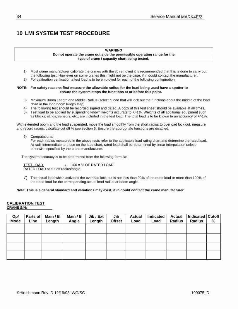
10 LMI SYSTEM TEST PROCEDURE
WARNING
Do not operate the crane out side the permissible operating range for the type of crane / capacity chart being tested.
1) Most crane manufacturer calibrate the cranes with the jib removed it is recommended that this is done to carry out the following test. How ever on some cranes this might not be the case, if in doubt contact the manufacturer.
2) For calibration verification a test load is to be employed for each of the following configuration;
NOTE: For safety reasons first measure the allowable radius for the load being used have a spotter to ensure the system stops the functions at or before this point.
3) Maximum Boom Length and Middle Radius (select a load that will lock out the functions about the middle of the load chart in the long boom length step)
4) The following test should be recorded signed and dated. A copy of this test sheet should be available at all times. 5) Test load to be applied by suspending known weights accurate to +/-1%. Weights of all additional equipment such
as blocks, slings, sensors, etc., are included in the test load. The total load is to be known to an accuracy of +/-1%. With extended boom and the load suspended, move the load smoothly from the short radius to overload lock out, measure and record radius, calculate cut off % see section 6. Ensure the appropriate functions are disabled.
6) Computations: For each radius measured in the above tests refer to the applicable load rating chart and determine the rated load. At radii intermediate to those on the load chart, rated load shall be determined by linear interpolation unless otherwise specified by the crane manufacturer.
The system accuracy is to be determined from the following formula: TEST LOAD x 100 = % OF RATED LOAD RATED LOAD at cut off radius/angle
7) The actual load which activates the overload lock out is not less than 90% of the rated load or more than 100% of the rated load for the corresponding actual load radius or boom angle.
Note: This is a general standard and variations may exist, if in doubt contact the crane manufacturer.
CALIBRATION TEST
CRANE S/N:_____________
Op/ Mode
Parts of Line
Main / B Length
Main / B Angle
Jib / Ext Length
Jib Offset
Actual Load
IndicatedLoad
Actual Radius
IndicatedRadius
Cutoff%

©Hirschmann Rev. D 12/19/08 WG/SC 190075_D
35
11 APPENDIX
2464 Roller Switch 4
Roller Switch 1
RS422 LOAD-
Roller Switch 2
Roller Switch 3
Analog Input 7
Analog Input 6
Analog Input 8
RS422 LOAD+
Analog Input 2
Analog Input 3
Analog Input 4
GND
GND
GND
GND
Analog Input 1
Analog Input 5
GND
GND
GND
GND
GND
GNDBLK (Piston Trans.)
BLK (Rod Trans.)
X1.
4142
#3 (C-reel GND) 4344
4546
BLU (Piston Signal) 5149
4748
50
#2 (C-Reel Length)
BLU (Rod Signal)
5352
5455
#4 (C-Reel Angle)
BLU (Console)56
5758
59
BLU/2 (S2 Signal)
BLU/2 (S1 Signal)
BRN/2 (S3 Optional)
RED (Console) 6061
6263
GND
+12 VDC
GND
X1.
+UDC12
Fuse 2A F1
Ref 3.8 VDC
Ref 1.0 VDC3
45
6
BRN (Piston.)
BRN/1 (S 1)
BRN/1 (S2)
BRN (Rod)
BRN/1 (S5)
+12VDC
11
RS232 CTS
RS232 RXD
RS232 TXD78
RS232 DTR
109
13
+12VDC
+12VDC
12
+12VDC
+12VDC
1415
+12VDC
+12VDC
1617
+12VDC
+12VDC
1819
+VREF 5VDC ANALOG
+12VDC
2021
2223
By-pass out
By-pass out
By-pass +
By-pass +
A-2-B BYPASS
A-2-B BYPASS
GND
A2B Switch Signal
A2B Switch +12VDC
Roller Switch 5
ANGLE / LENGTH
PROGR./ BUZZER
UP / TARE
8530 87a
8786
68
VIO (Console)
GRA/ PNK (Console)
BLK (Console)
6665
67
#6 C-Reel(A2B sign.)
#5 C-Reel(A2B 12V)
6970
7172
K5
By-P
ass switch
RED/ BLU (Console)
11
7374
12
7576
21 22 7977
7880
30VD
C/ 5A
YEL(Cons.)
GRN(Cons.)
GRA(Cons.)
PNK (Cons.)
BRN(Cons.)
WHT(Cons.)
28
Console RS422 CLK+
Console RS422 CLK-
2625
27
Console RS422 DATA+
Console RS422 DATA-
Console Power 24/12V
2930
Console GND
3132
Console RS422 TXD+
Console Shutoff
Console +12VDC
Console RS422 RXD+
Console RS422 RXD-
3334
3536
Console RS422 TXD-
Console Heating GND
Console Heating 24/12V
3937
3840
ATo C
onsole 118418
To P-Transd. piston
To P-Transd. rodBC
To Roller Sw
itch 1
To Roller Sw
itch 2
To Roller Sw
itch 3
To Roller Sw
itch 4
To Roller Sw
itch 5
F E DK GHTo C
able reel
Ref 3.8 VDC
slow blow
Ref 1.0 VDC
(+24 VDC)
#1 (C-Reel)
+VREF 5VDC ANALOG
+VREF 5VDC ANALOG
+VREF 5VDC ANALOG
+VREF 5VDC ANALOG
+VREF 5VDC ANALOG
Crane Voltage
-refer to Crane D
WG
.-
Not used
Not used
By-pass relay (GND)
BRN/2 (S4 Optional)BRN/2 (S5 Optional)
Crane V
oltage
Cut off D
evice (Crane C
omponent)
BRN/1 (S3)
BRN/1 (S4)
Note:
Rollersw
itch S1: on TiresR
ollerswitch S
2: on outriggersR
ollerswitch S
3 to S5: optional
To GND
MA
RK
4E/2 CEN
TRA
L UN
IT
Service Manual MARK4E/2
©Hirschmann Rev. D 12/19/08 WG/SC 190075_D
36
©Hirschmann Rev. D 12/19/08 WG/SC 190075_D
37

Service Manual MARK4E/2
©Hirschmann Rev. D 12/19/08 WG/SC 190075_D
38