![DELTSON - LM Guide Actuator...LM Guide Actuator [4-way Equal Load] Each circuit of balls is arranged at a contact angle of 45 so that the rated load on the inner block is uniform in](https://static.fdocuments.net/doc/165x107/5f70b647a8e0401e86170ea5/deltson-lm-guide-actuator-lm-guide-actuator-4-way-equal-load-each-circuit.jpg)
LM Guide - bachofen.ch · HCR Structure Balls roll in four rows of raceways precision-ground on an...
32
HCR/HMG LM Guide CATALOG No.306-8E , R Guide / Straight-Curved Guide Achieving a Simplified Mechanism For details, visit THK at www.thk.com *Product information is updated regularly on the THK website.
Transcript of LM Guide - bachofen.ch · HCR Structure Balls roll in four rows of raceways precision-ground on an...
HCR/HMG
LM Guide
CATALOG No.306-8E,
R Guide / Straight-Curved GuideAchieving a Simplified Mechanism
For details, visit THK at www.thk.com*Product information is updated regularly on the THK website.
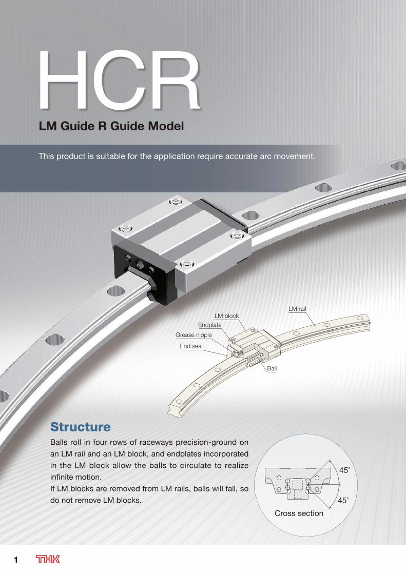
HCR
StructureBalls roll in four rows of raceways precision-ground on
an LM rail and an LM block, and endplates incorporated
in the LM block allow the balls to circulate to realize
infinite motion.
If LM blocks are removed from LM rails, balls will fall, so
do not remove LM blocks.
45°
45°
Cross section
This product is suitable for the application require accurate arc movement.
LM Guide R Guide Model
Ball
LM block
LM rail
Endplate
Grease nipple
End seal
1
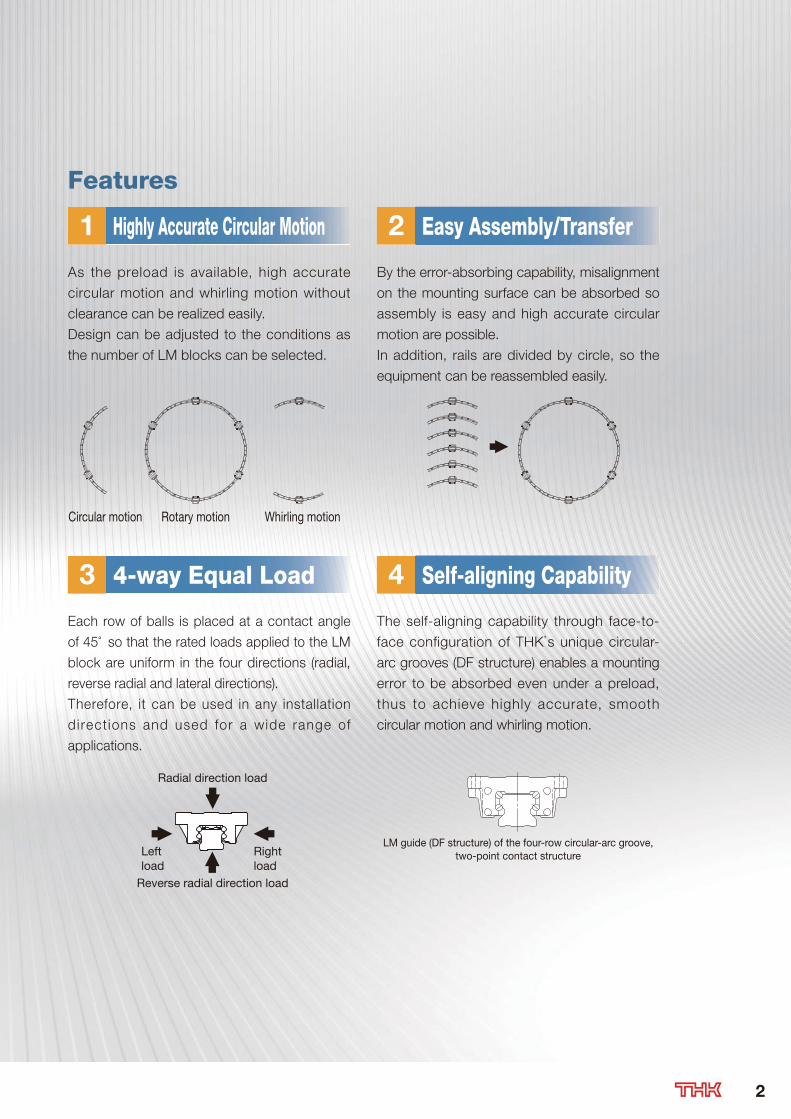
Features
1 2Highly Accurate Circular Motion Easy Assembly/Transfer
As the preload is available, high accurate
circular motion and whirling motion without
clearance can be realized easily.
Design can be adjusted to the conditions as
the number of LM blocks can be selected.
By the error-absorbing capability, misalignment
on the mounting surface can be absorbed so
assembly is easy and high accurate circular
motion are possible.
In addition, rails are divided by circle, so the
equipment can be reassembled easily.
3 44-way Equal Load Self-aligning Capability
Each row of balls is placed at a contact angle
of 45° so that the rated loads applied to the LM
block are uniform in the four directions (radial,
reverse radial and lateral directions).
Therefore, it can be used in any installation
di rect ions and used for a wide range of
applications.
The self-aligning capability through face-to-
face configuration of THK’s unique circular-
arc grooves (DF structure) enables a mounting
error to be absorbed even under a preload,
thus to achieve highly accurate, smooth
circular motion and whirling motion.
Circular motion Rotary motion Whirling motion
Radial direction load
Rightload
Leftload
Reverse radial direction load
LM guide (DF structure) of the four-row circular-arc groove,two-point contact structure
2
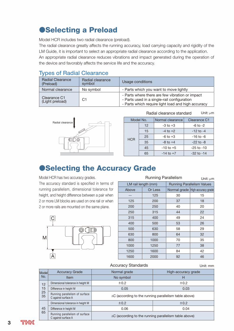
●Selecting a PreloadModel HCR includes two radial clearance (preload).
The radial clearance greatly affects the running accuracy, load carrying capacity and rigidity of the
LM Guide, it is important to select an appropriate radial clearance according to the application.
An appropriate radial clearance reduces vibrations and impact generated during the operation of
the device and favorably affects the service life and the accuracy.
Types of Radial ClearanceRadial Clearance (Preload)
Radial clearance symbol Usage conditions
Normal clearance No symbol - Parts which you want to move lightly
Clearance C1(Light preload) C1
- Parts where there are few vibration or impact- Parts used in a single-rail configuration- Parts which require light load and high accuracy
Radial clearance standard Unit: m
Radial clearanceModel No. Normal clearance Clearance C1
HCR
12 -3 to +3 -6 to -2
15 -4 to +2 -12 to -4
25 -6 to +3 -16 to -6
35 -8 to +4 -22 to -8
45 -10 to +5 -25 to -10
65 -14 to +7 -32 to -14
●Selecting the Accuracy GradeModel HCR has two accuracy grades.
The accuracy standard is specified in terms of
running parallelism, dimensional tolerance for
height, and height difference between a pair when
2 or more LM blocks are used on one rail or when
2 or more rails are mounted on the same plane.
M
C
A
Running Parallelism Unit: m
LM rail length (mm) Running Parallelism Values
Above Or Less Normal grade High-accuracy grade
125 30 15
125 200 37 18
200 250 40 20
250 315 44 22
315 400 49 24
400 500 53 26
500 630 58 29
630 800 64 32
800 1000 70 35
1000 1250 77 38
1250 1600 84 42
1600 2000 92 46
Accuracy Standards Unit: mm
Model No.
Accuracy Grade Normal grade High-accuracy grade
Item No symbol H
12152535
Dimensional tolerance in height M ±0.2 ±0.2
Difference in height M 0.05 0.03
Running parallelism of surface C against surface A C (according to the running parallelism table above)
4565
Dimensional tolerance in height M ±0.2 ±0.2
Difference in height M 0.06 0.04
Running parallelism of surface C against surface A C (according to the running parallelism table above)
3

●Optional PartThe following parts are available as optional parts of model HCR.
Select from them according to the conditions and environment.
For details of each optional product, see P.10, 11.
In normal environments (atmosphere and normal temperature) consider attaching the end seal
and side seal (option symbol: SS). (Option symbol of HCR12: UU)
Model HCR Optional Parts Correspondence List ●: Compatible
HCR OptionsSymbol
Size
12 15 25 35 45 65
Contam-ination protec-
tionacces-sories
End seal UU ● ● ● ● ● ●
End seal+Side seal SS - ● ● ● ● ●
Double seals+Side seal DD - ● ● ● ● ●
End seal+Side seal+Metal Scraper
ZZ - ● * ● ● ● ●
Double seals+Side seal+Metal Scraper
KK - ● * ● ● ● ●
Low resistance end seal LL - ● ● ● ● ●
Low resistance end seal+side seal
RR - ● ● ● ● ●
Dedicated capC - - ● ● ● ● ●
Dedicated capGC - - - ● ● ● ●
Maximum Resistance Value of Seal
This shows the maximum resistance value of seals per LM block with a lubricant applied.
Maximum resistance value of UU seal Unit: N
Model No. Seal symbol Seal Maximum Resistance Value
HCR
12
UU
1.2
15 2.0
25 3.9
35 11.8
45 19.6
65 34.3
*The model HCR15 ZZ and KK types do not support grease nipples.
4
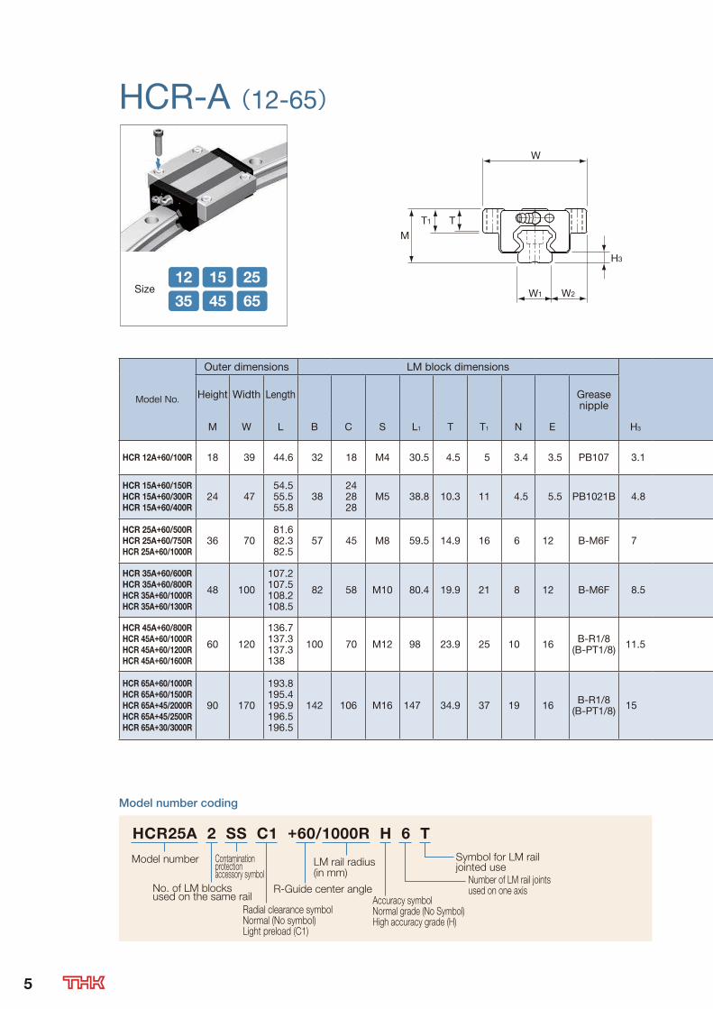
HCR-A (12-65)
Size12 15 25
35 45 65
W
MT
W1
T1
W2
H3
Model No.
Outer dimensions LM block dimensions
Height Width Length Grease nipple
M W L B C S L1 T T1 N E H3
HCR 12A+60/100R 18 39 44.6 32 18 M4 30.5 4.5 5 3.4 3.5 PB107 3.1
HCR 15A+60/150R
HCR 15A+60/300R
HCR 15A+60/400R
24 4754.555.555.8
38242828
M5 38.8 10.3 11 4.5 5.5 PB1021B 4.8
HCR 25A+60/500R
HCR 25A+60/750R
HCR 25A+60/1000R
36 7081.682.382.5
57 45 M8 59.5 14.9 16 6 12 B-M6F 7
HCR 35A+60/600R
HCR 35A+60/800R
HCR 35A+60/1000R
HCR 35A+60/1300R
48 100
107.2107.5108.2108.5
82 58 M10 80.4 19.9 21 8 12 B-M6F 8.5
HCR 45A+60/800R
HCR 45A+60/1000R
HCR 45A+60/1200R
HCR 45A+60/1600R
60 120
136.7137.3137.3138
100 70 M12 98 23.9 25 10 16 B-R1/8(B-PT1/8) 11.5
HCR 65A+60/1000R
HCR 65A+60/1500R
HCR 65A+45/2000R
HCR 65A+45/2500R
HCR 65A+30/3000R
90 170
193.8195.4195.9196.5196.5
142 106 M16 147 34.9 37 19 16 B-R1/8(B-PT1/8) 15
Model number coding
Symbol for LM rail jointed use
Accuracy symbolNormal grade (No Symbol)High accuracy grade (H)
LM rail radius (in mm)
Radial clearance symbol Normal (No symbol)Light preload (C1)
Contamination protection accessory symbol
Number of LM rail joints used on one axis R-Guide center angleNo. of LM blocks
used on the same rail
Model number
HCR25A 2 SS C1 +60/1000R H 6 T
5

n1-φ d1 through, φ d2 counter bore depth h
θ 2
θ 1 ( θ1)
4-S CB
θ(n1-1)×θ 2
L0
M1
N
(U)
RiR Ro
(E) (L1)
(L)
Unit: mm
LM rail dimensions Basic load rating Static permissible moment kN-m* Mass
Width Height C C0
MA MB MC
LMblock
LMrail
R R0 Ri L0 U W1 W2 M1 d1×d2×h n1 ° 1° 2° kN kN 1 block
Double blocks
1 block
Double blocks
1 block kg kg/m
100 106 94 100 13.4 12 13.5 11 3.5×6×5 3 60 7 23 4.7 8.53 0.0409 0.228 0.0409 0.228 0.0445 0.08 0.83
150300400
157.5307.5407.5
142.5292.5392.5
150300400
20.14054
15 16 15 4.5×7.5×5.3357
60763
2312
9
6.668.338.33
10.813.513.5
0.0805 0.457 0.0805 0.457 0.0844 0.2 1.5
500750
1000
511.5761.5
1011.5
488.5738.5988.5
500750
1000
67100134
23 23.5 22 7×11×99
1215
6022.52
754
19.9 34.4 0.307 1.71 0.307 1.71 0.344 0.59 3.3
600800
10001300
617817
10171317
583783983
1283
600800
10001300
80107134174
34 33 29 9×14×12
7111217
60
32.52.52
95.553.5
37.3 61.1 0.782 3.93 0.782 3.93 0.905 1.6 6.6
800100012001600
822.51022.51222.51622.5
777.5977.5
1177.51577.5
800100012001600
107134161214
45 37.5 38 14×20×17
8101215
60
232.52
8654
60 95.6 1.42 7.92 1.42 7.92 1.83 2.8 11.0
10001500200025003000
1031.51531.52031.52531.53031.5
968.51468.51968.52468.52968.5
10001500153119131553
134201152190102
63 53.5 53 18×26×22
810121310
6060454530
230.51.51.5
8643.53
141 215 4.8 23.5 4.8 23.5 5.82 8.5 22.5
Note) LM rail radiuses other than the radiuses in the above table are also available. Contact THK for details.
The R-Guide center angles in the table are maximum manufacturing angles. To obtain angles greater than
them, rails must be additionally connected. Contact THK for details.
Static permissible moment*: 1 block: static permissible moment value with 1 LM block
Double blocks: static permissible moment value with 2 blocks closely contacting
with each other
*Lubrication
Lithium soap base grease No. 2 (AFB-LF grease) is contained in model HCR as standard.
If you want any other grease or any types without grease, contact THK.
6

LM Block Dimensions with Optional Parts●Dimensions with Contamination Protection Accessories
Contamination Protection AccessoriesContamination Protection Accessories
L
Unit: mm
Model No.L
UU SS DD ZZ KK LL RR
HCR
12A+60/100R 44.6
15A+60/150R 54.5 54.5 59.7 54.5 54.5
15A+60/300R 55.5 55.5 60.7 57.1* 62.3* 55.5 55.5
15A+60/400R 55.8 55.8 61 57.3* 62.5* 55.8 55.8
25A+60/500R 81.6 81.6 89.2 85.5 93.1 81.6 81.6
25A+60/750R 82.3 82.3 89.9 86 93.6 82.3 82.3
25A+60/1000R 82.5 82.5 90.1 86.2 93.8 82.5 82.5
35A+60/600R 107.2 107.2 114.8 111.2 118.8 107.2 107.2
35A+60/800R 107.5 107.5 115.1 111.5 119.1 107.5 107.5
35A+60/1000R 108.2 108.2 115.8 112 119.6 108.2 108.2
35A+60/1300R 108.5 108.5 116.1 112.3 119.8 108.5 108.5
45A+60/800R 136.7 136.7 143.9 142.1 149.2 136.7 136.7
45A+60/1000R 137.3 137.3 144.5 142.7 149.9 137.3 137.3
45A+60/1200R 137.3 137.3 144.5 142.7 149.9 137.3 137.3
45A+60/1600R 138 138 145.2 143.3 150.5 138 138
65A+60/1000R 193.8 193.8 201 199.4 206.6 193.8 193.8
65A+60/1500R 195.4 195.4 202.6 200.8 208 195.4 195.4
65A+60/2000R 195.9 195.9 203.1 201.3 208.5 195.9 195.9
65A+60/2500R 196.5 196.5 203.7 201.8 209 196.5 196.5
65A+60/3000R 196.5 196.5 203.7 201.8 209 196.5 196.5
*The model HCR15 ZZ and KK types do not support grease nipples.
●Calculating the Static Safety FactorIn a system subject to frequent starts and stops, placed under cutting forces or under a large
moment caused by an overhang load, an excessively large load may apply to the LM Guide.
When selecting a model number, make sure that the desired model is capable of receiving the
required maximum load (whether stationary or in motion) and calculate the static safety factor.
When the radial load is large ≧fSPR
fH fT fC C0
When the reverse radial load is large ≧fS
PL
fH fT fC C0L
When the lateral loads are large ≧fS
PT
fH fT fC C0T
fS :Static safety factor
C0 :Basic static load rating (radial direction) (N)C0L :Basic static load rating (reverse radial direction) (N)C0T :Basic static load rating (lateral direction) (N)PR :Calculated load (radial direction) (N)PL :Calculated load (reverse radial direction) (N)PT :Calculated load (lateral direction) (N)fH :Hardness factor
fT :Temperature factor
fC :Contact factor
Reference Values of Static Safety Factor (fS)Machine using the LM system Load conditions Lower limit of fS
General industrial machinery
Without vibration or impact 1.0 to 3.5With vibration or impact 2.0 to 5.0
Machine toolWithout vibration or impact 1.0 to 4.0With vibration or impact 2.5 to 7.07
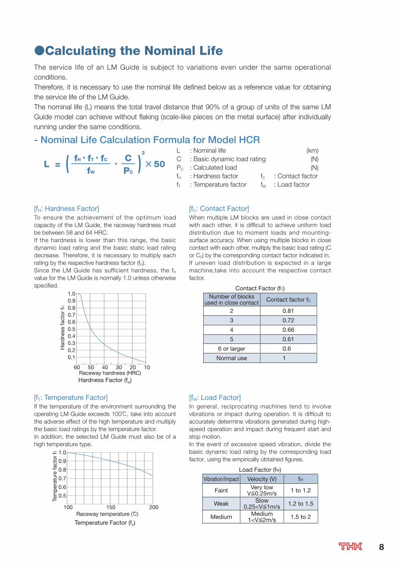
●Calculating the Nominal LifeThe service life of an LM Guide is subject to variations even under the same operational
conditions.
Therefore, it is necessary to use the nominal life defined below as a reference value for obtaining
the service life of the LM Guide.
The nominal life (L) means the total travel distance that 90% of a group of units of the same LM
Guide model can achieve without flaking (scale-like pieces on the metal surface) after individually
running under the same conditions.
- Nominal Life Calculation Formula for Model HCR
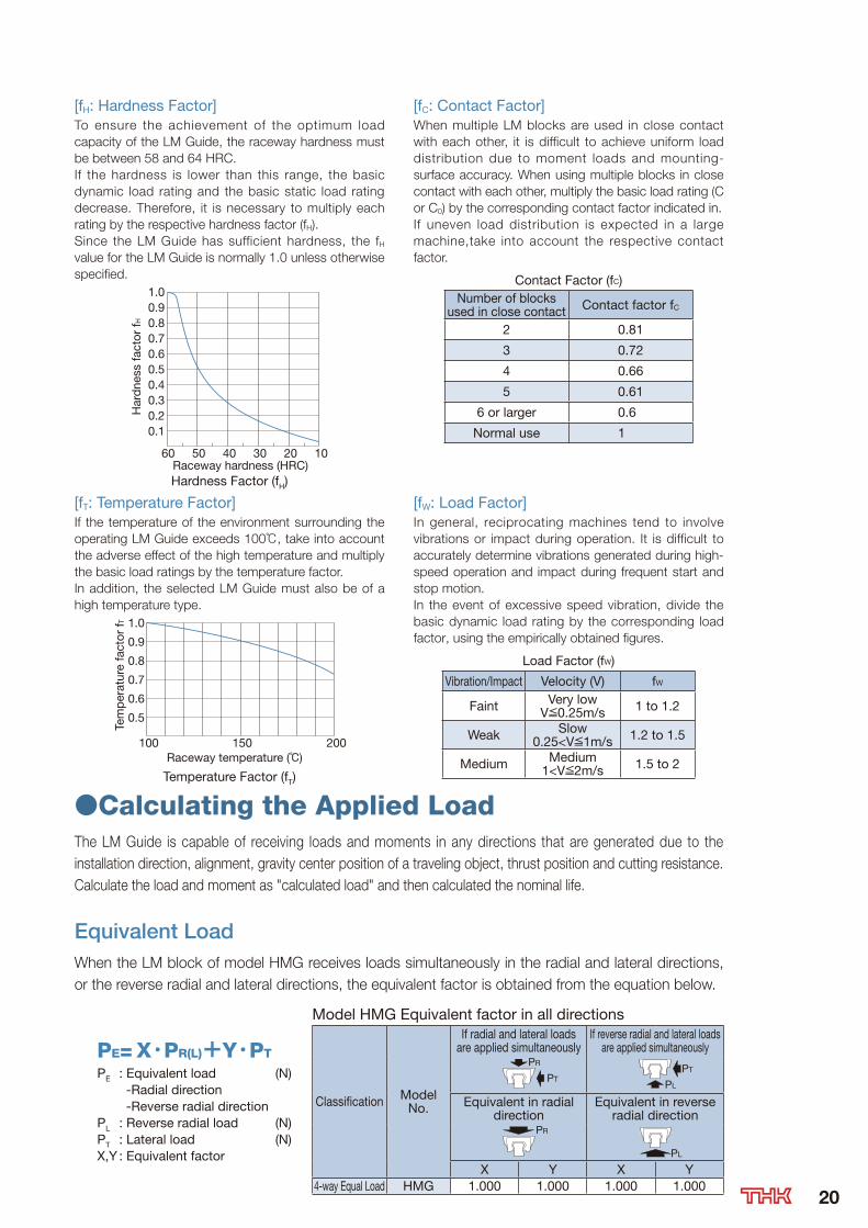
[fH: Hardness Factor]To ensure the achievement of the optimum load
capacity of the LM Guide, the raceway hardness must
be between 58 and 64 HRC.
If the hardness is lower than this range, the basic
dynamic load rating and the basic static load rating
decrease. Therefore, it is necessary to multiply each
rating by the respective hardness factor (fH).
Since the LM Guide has sufficient hardness, the fH
value for the LM Guide is normally 1.0 unless otherwise
specified.
Raceway hardness (HRC)
Har
dne
ss fa
ctor
f H
1.00.90.80.70.60.50.40.30.20.1
60 50 40 30 20 10
Hardness Factor (fH)
[fC: Contact Factor]When multiple LM blocks are used in close contact
with each other, it is difficult to achieve uniform load
distribution due to moment loads and mounting-
surface accuracy. When using multiple blocks in close
contact with each other, multiply the basic load rating (C
or C0) by the corresponding contact factor indicated in.
If uneven load distribution is expected in a large
machine,take into account the respective contact
factor.
Contact Factor (fC)Number of blocks
used in close contact Contact factor fC
2 0.81
3 0.72
4 0.66
5 0.61
6 or larger 0.6
Normal use 1
[fT: Temperature Factor]If the temperature of the environment surrounding the
operating LM Guide exceeds 100℃, take into account
the adverse effect of the high temperature and multiply
the basic load ratings by the temperature factor.
In addition, the selected LM Guide must also be of a
high temperature type.
Raceway temperature (℃)
Tem
per
atur
e fa
ctor
f T
0.8
0.9
1.0
0.7
0.6
0.5
100 150 200
Temperature Factor (fT)
[fW: Load Factor]In general, reciprocating machines tend to involve
vibrations or impact during operation. It is difficult to
accurately determine vibrations generated during high-
speed operation and impact during frequent start and
stop motion.
In the event of excessive speed vibration, divide the
basic dynamic load rating by the corresponding load
factor, using the empirically obtained figures.
Load Factor (fW)
Vibration/Impact Velocity (V) fW
Faint Very lowV≦0.25m/s 1 to 1.2
Weak Slow0.25<V≦1m/s 1.2 to 1.5
Medium Medium1<V≦2m/s 1.5 to 2
50L = • CPC
fH•fT•fC
fW( )
3 L : Nominal life (km)
C : Basic dynamic load rating (N)
PC : Calculated load (N)
fH : Hardness factor fC : Contact factor
fT : Temperature factor fW : Load factor
8

●Calculating the Applied LoadThe LM Guide is capable of receiving loads and moments in any directions that are generated due to the
installation direction, alignment, gravity center position of a traveling object, thrust position and cutting resistance.
Calculate the load and moment as "calculated load" and then calculated the nominal life.
Equivalent LoadWhen the LM block of model HCR receives loads simultaneously in the radial and lateral directions,
or the reverse radial and lateral directions, the equivalent factor is obtained from the equation below.
PE= X•PR(L)+Y•PT
PE : Equivalent load (N) -Radial direction -Reverse radial directionPL : Reverse radial load (N)PT : Lateral load (N)X,Y : Equivalent factor
Model HCR Equivalent factor in all directions
Classification Model No.
If radial and lateral loads are applied simultaneously
If reverse radial and lateral loads are applied simultaneously
PR
PTPT
PL
Equivalent in radial direction
Equivalent in reverse radial direction
PR
X Y X Y4-way Equal Load HCR 1.000 1.000 1.000 1.000
Rated Loads in All DirectionsModel HCR can bear loads and moments in any directions, including a radial load (PR), reverse
radial load (PL) and lateral loads (PT), simultaneously.
The basic load rating is equal in four directions (radial, reverse radial and lateral directions), and
their values are expressed in the corresponding specification tables of model HCR.
Model HCR Rated Loads in all directions
Classification Model No.
Reverse radial direction Lateral direction
PL
PT PT
Dynamic load ratingCL
Static load ratingC0L
Dynamic load ratingCT
Static load ratingC0T
4-way Equal Load HCR C C0 C C0
PL
●Materials of Block and RailModel HCR uses carbon steel for both LM blocks and rails.
If you want types strong against rust, use surface treatment.
●LM Rail Joint TypeIf the LM Guide is used in whirling motion or rotational motion, the LM rail joint type is available.
To use the joint type, combine the joint marks displayed on the LM rails.
When two LM Guides with connected rails are to be arranged in parallel to each other, the two LM Guides
will be manufactured so that the two LM Guides are axisymmetrically aligned.
If a large load is applied near the LM rail joint, the LM rail may deflect and cause misalignment.
Therefore, we recommend securely fastening the joint section by pressing the LM rail against the datum
plane using a set screw or the like and keeping distance between mounting holes including butt joint portion.
Contact THK for details.
9

●Surface Treatment of the LM GuideFor the LM Guide, three types of surface treatment, THK-AP treatment, are available for the
purpose of corrosion resistance and appearance.
Surface Treatment Features Appearance
AP-HC
Equivalent to industrial-use hard chrome plating, AP-HC achieves almost the same level of corrosion resistance as martensite stainless steel.In addition, it is highly wear resistant since the film hardness is extremely high, 750 HV or higher.
AP-CA type of industrial-use black chrome coating designed to increase corrosion resistance. It achieves lower cost and higher corrosion resis-tance than martensite stainless steel.
AP-CFA compound treatment that combines black chrome coating and special fluorine resin coat-ing and is suitable for applications requiring corrosion resistance.
Note that the inside of the mounting hole of the LM blocks and LM rail is not provided with surface treatment.
In addition to the above treatments, other surface treatments are sometimes performed on areas
other than the raceways, such as alkaline coloring treatment (black oxidizing) and color anodize
treatment. However, some of them are not suitable for LM systems. For details, contact THK.
If using an LM system whose raceways are surface treated, set a higher safety factor.
●Contamination Protection Accessories to Attach to LM Blocks
End SealThis is a general seal to attach to both ends of a LM block.
Attach this in normal environments (atmosphere and room temperature) and contami-
nated environments (dust and cutting chips).
One of its purposes is to remove dust from the upper face and side face of the LM rail.
In addition to contamination protection, it is also a purpose to retain the lubricant in the
LM block.
End sealEnd seal
Side SealThis is a general seal to attach to the lower part of a LM block.
Attach this in normal environments (atmosphere and room temperature) and
contaminated environments (dust and cutting chips).
Its purpose is to prevent entrance of dust from the bottom of the LM block.
This contamination protection accessory is especially useful for environ-
ments where the mounting orientation is inverted mount or dust flutters.
Side sealSide seal
Double SealsThese seals are double-end seals to attach to both ends of the LM block.
Its purpose is to remove dust and cutting chips from parts with much dust
and cutting chips.
Note that it extends the overall length of the LM blocks.
For the overall length of the LM blocks, see the specification table of each
LM Guide type.
End seal
End sealEnd sealSpacer
With hexagonal socketsButton bolt
10

Metal Scraper (Non-contact)This is a metallic non-contact seal to attach to both ends of a LM block.
Be sure to attach this in environments where the sputter of welding, etc. adheres
to the LM rail. If the normal end seal is used alone, it will be damaged soon.
Note that it extends the overall length of the LM blocks.
For the overall length of the LM blocks, see the specification table of each LM
Guide type.
With hexagonal sockets
End seal
Metal Scraper
Button bolt
Metal Scraper
Low-resistance SealThis is a seal to attach to both ends of a LM block.
Use this if you want lower resistance than that of the
end seal.
One of its purposes is to remove dust from the upper
face and side face of the LM rail.
Low-resistance SealLow-resistance Seal
●Contamination Protection Accessories to Attach to LM RailDedicated Cap C (C Cap)
This is a special resin caps designed to cover the mounting holes in LM rails.
Preventing any influx of cutting chips or foreign material from the top face of the LM rail into the LM block,
coupled with the use of seals, will improve the contamination protection performance for the LM guide.
Cap C
LM rail
φD
H
Dedicated Cap GC (GC Cap)
This is a metal cap designed to cover the mounting holes on LM rails (in compliance with RoHS directives).
Preventing any influx of coolant or minute foreign material from the top face of the LM rail into the LM block more by C
cap, coupled with the use of seals, will dramatically improve the contamination protection performance for the LM guide.
Cap GC
LM rail
φD
H
●Model HCR C cap support list Unit: mm
HCRSize
12 15 25 35 45 65
C cap Model No. C3 C4 C6 C8 C12 C16
Bolt used M3 M4 M6 M8 M12 M16
Main dimensions
D 6.3 7.9 11.6 14.5 20.5 26.5
H 1.2 1.0 2.7 3.7 4.7 5.7
●Model HCR GC cap support list Unit: mm
HCRSize
12 15 25 35 45 65
GC cap Model No. - - GC6 GC8 GC12 GC16
Bolt used - - M6 M8 M12 M16
Main dimensions
D - - 11.36 14.36 20.36 26.36
H - - 2.5 3.5 4.6 5.0
- LM guides with GC caps are special rails.
11

●Shoulder Height of the Mounting Base and the Corner RadiusNormally, the mounting base for the LM rail and the LM block has a reference-surface on the sideface
of the shoulder of the base in order to allow easy installation and highly accurate positioning.
The corner of the mounting shoulder must be machined to have a recess, or machined to be smaller
than the corner radius “r,” to prevent interference with the chamfer of the LM rail or the LM block.
LM rail section
LM rail
LM block
LM block section
H1r1
r2
r2
r1
H2
H3
Unit: mm
Model No.LM rail
Corner radiusLM block
Corner radiusLM rail
shoulder heightLM block
maximum shoulder heightr1(max) r2(max) H1 H2 H3
HCR
12 0.8 0.5 2.6 6 3.1
15 0.5 0.5 3 4 4.8
25 1 1 5 5 7
35 1 1 6 6 8.5
45 1 1 8 8 11.5
65 1.5 1.5 10 10 15
Recommended Tightening Torque for LM Rails
It is recommended to apply the screw tightening torque
value when mounting the LM rails to the machine.
The tightening torque varies according to the material of
the counterpart.
Tightening torque when Hexagonal-Socket-Head type bolts are used
Unit: N-cm
Screw model
Tightening torque
Steel Cast Iron Aluminum
M3 196 127 98
M4 412 274 206
M6 1370 921 686
M8 3040 2010 1470
M12 11800 7840 5880
M16 19600 13100 9800
●Procedure to Mount the LM GuideThe LM Guide can be mounted easily with high accuracy by removing the burr, dent or dust on the mounting surface of the counterpart to
which the LM Guide is to be mounted and mounting it as specified in the procedure.
To install the LM rails of R Guide model HCR, we recommend having any form of datum point (such as a pin) on the reference side (inside) of
the LM rail, and pressing the LM rail to the datum point then stopping the LM rail with a presser plate from the counter-reference surface.
Joint
Method for Securing the LM Rails at the Joint Method for Securing the LM Rail Using a Pin as a Datum Point12

45°
45°
Cross section
HMG
StructureBalls roll in four rows of raceways precision-ground on an LM
rail and an LM block, and endplates incorporated in the LM
block allow the balls to circulate to realize infinite motion.
Since retainer plates hold the balls, they do not fall off even if
the LM block is pulled out from LM rail.
(Ball may fall depending on the handling. Use dummy rail when
removing the LM block.
When mounting the LM block on an LM rail, slide it onto a
straight rail or a joint rail.)
LM Guide Straight-Curved Guide Model HMG
LM block
LM rail
Straight-Curved seal
Endplate
Ball
Curved rail Joint rail Straight rail
LM Guide enabling both linear and curved motion at the same time.
SSSSSSSSSStructureBBalls roll in four rows of raceways precision-ground on an LM
rail and an LM block, and endplates incorporated in the LM
bl k ll th b ll t i l t t li i fi it ti
LLMLM block
LM rail
Straight-Curved seal
Endplate
Ball
Curved rail Joint rail Straig
LM Guide enabling both linear and curved motion at the same time.
13
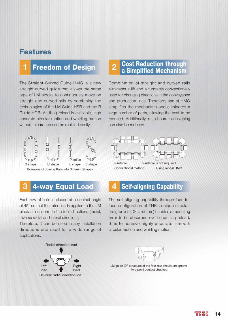
Features
1 2Freedom of Design Cost Reduction through a Simplified Mechanism
The Straight-Curved Guide HMG is a new
straight-curved guide that allows the same
type of LM blocks to continuously move on
straight and curved rails by combining the
technologies of the LM Guide HSR and the R
Guide HCR. As the preload is available, high
accurate circular motion and whirling motion
without clearance can be realized easily.
Combination of straight and curved rails
eliminates a lift and a turntable conventionally
used for changing directions in the conveyance
and production lines. Therefore, use of HMG
simplifies the mechanism and eliminates a
large number of parts, allowing the cost to be
reduced. Additionally, man-hours in designing
can also be reduced.
3 44-way Equal Load Self-aligning Capability
Each row of balls is placed at a contact angle
of 45° so that the rated loads applied to the LM
block are uniform in the four directions (radial,
reverse radial and lateral directions).
Therefore, it can be used in any installation
directions and used for a wide range of
applications.
The self-aligning capability through face-to-
face configuration of THK’s unique circular-
arc grooves (DF structure) enables a mounting
error to be absorbed even under a preload,
thus to achieve highly accurate, smooth
circular motion and whirling motion.
Radial direction load
Rightload
Leftload
Reverse radial direction loa
LM guide (DF structure) of the four-row circular-arc groove,two-point contact structure
S shapeL shapeU shapeO shape
Examples of Joining Rails into Different Shapes Using model HMGConventional method
Turntable is not requiredTurntable
14

15
●Selecting a PreloadModel HMG includes two radial clearance (preload).The radial clearance greatly affects the running accuracy, load carrying capacity and rigidity of the LM Guide, it is important to select an appropriate radial clearance according to the application.An appropriate radial clearance reduces vibrations and impact generated during the operation of the device and favorably affects the service life and the accuracy.
Types of Radial ClearanceRadial Clearance (Preload)
Radial clearance symbol Usage conditions
Normal clearance No symbol - Parts which you want to move lightly
Clearance C1(Light preload) C1
- Parts where there are few vibration or impact- Parts used in a single-rail configuration- Parts which require light load and high accuracy
Radial clearance standard Unit: m
Radial clearanceModel No. Normal clearance Clearance C1
HMG
15 -4 to +2 -12 to -4
25 -6 to +3 -16 to -6
35 -8 to +4 -22 to -8
45 -10 to +5 -25 to -10
65 -14 to +7 -32 to -14
●Selecting the Accuracy GradeModel HMG is available in normal grade only.The accuracy standard is specified in terms of running parallelism, dimensional tolerance for height/width, and height/width difference between a pair when 2 or more LM blocks are used on one rail or when 2 or more rails are mounted on the same plane.(A gap is created at curved sections)
Running Parallelism Unit: m
LM rail length (mm) Running Parallelism ValuesAbove Or Less Normal grade 125 30125 200 37200 250 40250 315 44315 400 49400 500 53500 630 58630 800 64800 1000 70
1000 1250 771250 1600 841600 2000 92
Accuracy Standards Unit: mm
Model No.
Accuracy Grade Normal gradeItem No symbol
15
Dimensional tolerance in height M ±0.1Difference in height M 0.02Dimensional tolerance in width W2 ±0.1Dimensional in width W2 0.02Running parallelism of surface C against surface A
C (according to the running parallelism table above)
Running parallelism of surface D against surface B
D (according to the running parallelism table above)
2535
Dimensional tolerance in height M ±0.1Difference in height M 0.02Dimensional tolerance in width W2 ±0.1Dimensional in width W2 0.03Running parallelism of surface C against surface A
C (according to the running parallelism table above)
Running parallelism of surface D against surface B
D (according to the running parallelism table above)
4565
Dimensional tolerance in height M ±0.1Difference in height M 0.03Dimensional tolerance in width W2 ±0.1Dimensional in width W2 0.03Running parallelism of surface C against surface A
C (according to the running parallelism table above)
Running parallelism of surface D against surface B
D (according to the running parallelism table above)
B
M
W2
C
D
A
16
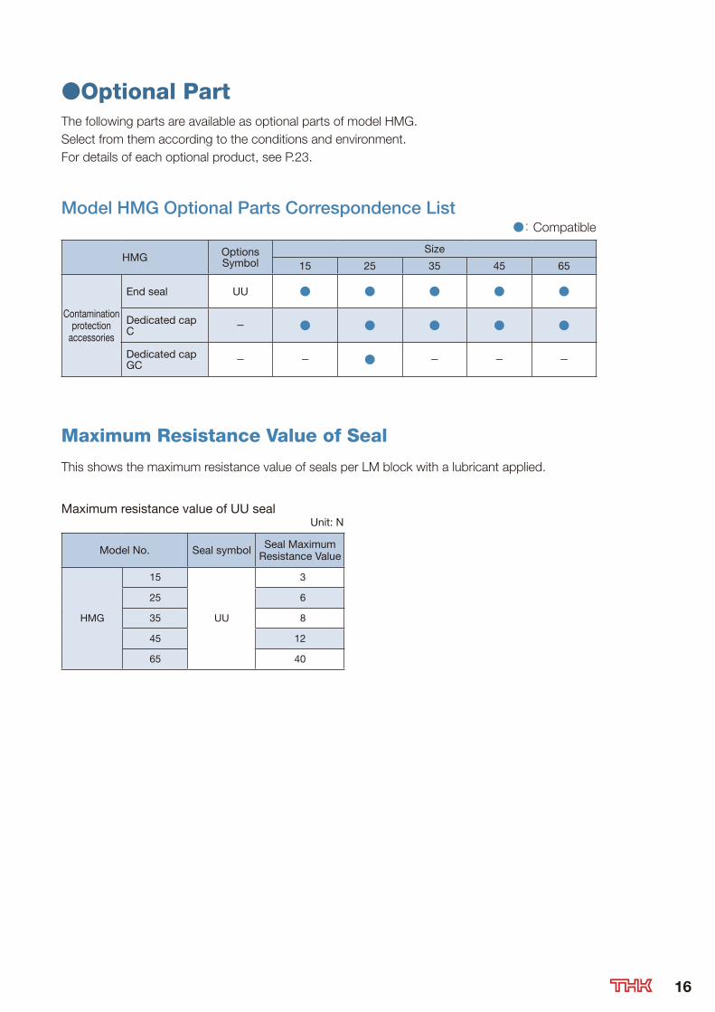
●Optional PartThe following parts are available as optional parts of model HMG.
Select from them according to the conditions and environment.
For details of each optional product, see P.23.
Model HMG Optional Parts Correspondence List ●: Compatible
HMG OptionsSymbol
Size
15 25 35 45 65
Contamination protection
accessories
End seal UU ● ● ● ● ●
Dedicated capC - ● ● ● ● ●
Dedicated capGC - - ● - - -
Maximum Resistance Value of Seal
This shows the maximum resistance value of seals per LM block with a lubricant applied.
Maximum resistance value of UU seal Unit: N
Model No. Seal symbol Seal Maximum Resistance Value
HMG
15
UU
3
25 6
35 8
45 12
65 40

HMG-A(15-65)
Size15 25 35
45 65
Model No.
Outer dimensions LM block dimensions LM rail dimensions
LM rail Height
M W L L´ B S×ℓ L1 N E W1 W2 F M1
HMG 15A 24 47 48 28.8 38 M5×11 16 4.3 5.5 15 16 60 15
HMG 25A 36 70 62.2 42.2 57 M8×16 25.6 6 12 23 23.5 60 22
HMG 35A 48 100 80.6 54.6 82 M10×21 32.6 8 12 34 33 80 29
HMG 45A 60 120 107.6 76.6 100 M12×25 42.6 10 16 45 37.5 105 38
HMG 65A 90 170 144.4 107.4 142 M16×37 63.4 19 16 63 53.5 150 53
Model number coding
Center angle of one outer curved rail
Radius of outer curved rail
No. of outer curved LM rails jointed
Symbol for linear LM rail joint
Center angle of one inner curved rail
Symbol for No. of rails used on the same plane
Radius of inner curved rail
No. of inner curved LM rails jointed
Radial clearance symbol Normal (No symbol)Light preload (C1)
Contamination protectionaccessory symbol
Overall linear LM rail length per rail
No. of LM blocksused on the same rail
Model number
HMG15A 2 UU C1 +1000L T + 60/150R 6T + 60/300R 6T -II
500
R 300
R 1
5060°
60°
60°
Example of model No.
BW
W2W1
M
(E)(L)
L1
N
B
2-S×ℓ
(L')
〃〃
17

Curved rail
Straight rail
θ1
θ
R
M1
d2
d1F
h
B
(n-1)×θ2
θ1θ2
Unit: mm
Basic dynamic load rating (C) Basic static load rating (C0)
Mounting hole Curved rail
d1×d2×h R n ° 1° 2° Resultant load(C) kN
Straight section (C0st) kN
Curved section (C0r) kN
4.5×7.5×5.3150300400
357
606060
763
2312
92.56 4.23 0.44
7×11×9500750
1000
91215
606060
22.52
754
9.41 10.8 6.7
9×14×12
600800
10001300
7111217
60606060
32.52.52
95.553.5
17.7 19 11.5
14×20×17
800100012001600
8101215
60606060
232.52
8654
28.1 29.7 18.2
18×26×22
10001500200025003000
810121310
6060454530
230.51.51.5
8643.53
66.2 66.7 36.2
When a moment is applied where one LM block is specified per axis, the LM block may experience non-smooth motion.
We recommend that multiple LM blocks be used per axis when a moment is applied.
Table shows the static permissible moment of an LM block in the MA, MB and MC directions.
Static Permissible Moments of Model HMG Unit: kN-m
Model No.
MA MB MC
Straight section Curved section Straight section Curved section Straight section Curved sectionHMG 15A 0.008 0.007 0.008 0.01 0.027 0.003HMG 25A 0.1 0.04 0.1 0.05 0.11 0.07HMG 35A 0.22 0.11 0.22 0.12 0.29 0.17HMG 45A 0.48 0.2 0.48 0.22 0.58 0.34HMG 65A 1.47 0.66 1.47 0.73 1.83 0.94
*Lubrication
Lithium soap base grease No. 2 (AFB-LF grease) is contained in model HMG as standard.
If you want any other grease or any types without grease, contact THK.
18

LM Block Dimensions with Optional Parts●Dimensions with Contamination Protection Accessories
Contamination Protection Accessories
Contamination Protection Accessories
LUnit:mm
Model No.L
UU
HMG
15A 48
25A 62.2
35A 80.6
45A 107.6
65A 144.4
●Calculating the Static Safety FactorIn a system subject to frequent starts and stops, placed under cutting forces or under a large
moment caused by an overhang load, an excessively large load may apply to the LM Guide.
When selecting a model number, make sure that the desired model is capable of receiving the
required maximum load (whether stationary or in motion) and calculate the static safety factor.
When the radial load is large ≧fSPR
fH fT fC C0
When the reverse radial load is large ≧fS
PL
fH fT fC C0L
When the lateral loads are large ≧fS
PT
fH fT fC C0T
fS :Static safety factor
C0 :Basic static load rating (radial direction) (N)C0L :Basic static load rating (reverse radial direction) (N)C0T :Basic static load rating (lateral direction) (N)PR :Calculated load (radial direction) (N)PL :Calculated load (reverse radial direction) (N)PT :Calculated load (lateral direction) (N)fH :Hardness factor
fT :Temperature factor
fC :Contact factor
Reference Values of Static Safety Factor (fS)Machine using the LM system Load conditions Lower limit of fS
General industrial machinery
Without vibration or impact 1.0 to 3.5With vibration or impact 2.0 to 5.0
Machine toolWithout vibration or impact 1.0 to 4.0With vibration or impact 2.5 to 7.0
●Calculating the Nominal LifeThe service life of an LM Guide is subject to variations even under the same operational
conditions.
Therefore, it is necessary to use the nominal life defined below as a reference value for obtaining
the service life of the LM Guide.
The nominal life (L) means the total travel distance that 90% of a group of units of the same LM
Guide model can achieve without flaking (scale-like pieces on the metal surface) after individually
running under the same conditions.
- Nominal Life Calculation Formula for Model HMG
50L = • CPC
fH•fT•fC
fW( )
3 L : Nominal life (km)
C : Basic dynamic load rating (N)
PC : Calculated load (N)
fH : Hardness factor fC : Contact factor
fT : Temperature factor fW : Load factor
19
[fH: Hardness Factor]To ensure the achievement of the optimum load
capacity of the LM Guide, the raceway hardness must
be between 58 and 64 HRC.
If the hardness is lower than this range, the basic
dynamic load rating and the basic static load rating
decrease. Therefore, it is necessary to multiply each
rating by the respective hardness factor (fH).
Since the LM Guide has sufficient hardness, the fH
value for the LM Guide is normally 1.0 unless otherwise
specified.
Raceway hardness (HRC)
Har
dne
ss fa
ctor
f H
1.00.90.80.70.60.50.40.30.20.1
60 50 40 30 20 10
Hardness Factor (fH)
[fC: Contact Factor]When multiple LM blocks are used in close contact
with each other, it is difficult to achieve uniform load
distribution due to moment loads and mounting-
surface accuracy. When using multiple blocks in close
contact with each other, multiply the basic load rating (C
or C0) by the corresponding contact factor indicated in.
If uneven load distribution is expected in a large
machine,take into account the respective contact
factor.
Contact Factor (fC)Number of blocks
used in close contact Contact factor fC
2 0.81
3 0.72
4 0.66
5 0.61
6 or larger 0.6
Normal use 1
[fT: Temperature Factor]If the temperature of the environment surrounding the
operating LM Guide exceeds 100℃, take into account
the adverse effect of the high temperature and multiply
the basic load ratings by the temperature factor.
In addition, the selected LM Guide must also be of a
high temperature type.
Raceway temperature (℃)
Tem
per
atur
e fa
ctor
f T
0.8
0.9
1.0
0.7
0.6
0.5
100 150 200
Temperature Factor (fT)
[fW: Load Factor]In general, reciprocating machines tend to involve
vibrations or impact during operation. It is difficult to
accurately determine vibrations generated during high-
speed operation and impact during frequent start and
stop motion.
In the event of excessive speed vibration, divide the
basic dynamic load rating by the corresponding load
factor, using the empirically obtained figures.
Load Factor (fW)
Vibration/Impact Velocity (V) fW
Faint Very lowV≦0.25m/s 1 to 1.2
Weak Slow0.25<V≦1m/s 1.2 to 1.5
Medium Medium1<V≦2m/s 1.5 to 2
●Calculating the Applied LoadThe LM Guide is capable of receiving loads and moments in any directions that are generated due to the
installation direction, alignment, gravity center position of a traveling object, thrust position and cutting resistance.
Calculate the load and moment as "calculated load" and then calculated the nominal life.
Equivalent LoadWhen the LM block of model HMG receives loads simultaneously in the radial and lateral directions,
or the reverse radial and lateral directions, the equivalent factor is obtained from the equation below.
PE= X•PR(L)+Y•PT
PE : Equivalent load (N) -Radial direction -Reverse radial directionPL : Reverse radial load (N)PT : Lateral load (N)X,Y : Equivalent factor
Model HMG Equivalent factor in all directions
Classification Model No.
If radial and lateral loads are applied simultaneously
If reverse radial and lateral loads are applied simultaneously
PR
PTPT
PL
Equivalent in radial direction
Equivalent in reverse radial direction
PR
X Y X Y4-way Equal Load HMG 1.000 1.000 1.000 1.000
PL
20
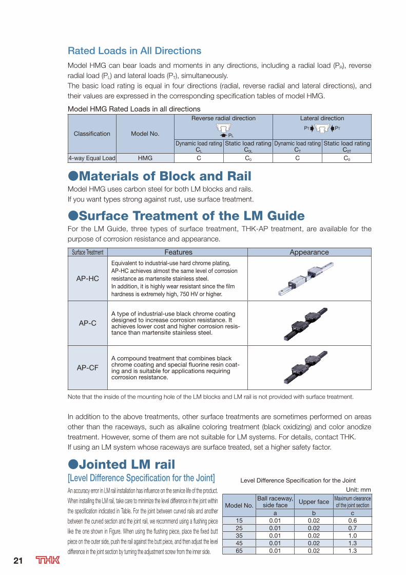
●Materials of Block and RailModel HMG uses carbon steel for both LM blocks and rails.
If you want types strong against rust, use surface treatment.
●Surface Treatment of the LM GuideFor the LM Guide, three types of surface treatment, THK-AP treatment, are available for the
purpose of corrosion resistance and appearance.
Surface Treatment Features Appearance
AP-HC
Equivalent to industrial-use hard chrome plating, AP-HC achieves almost the same level of corrosion resistance as martensite stainless steel.In addition, it is highly wear resistant since the film hardness is extremely high, 750 HV or higher.
AP-CA type of industrial-use black chrome coating designed to increase corrosion resistance. It achieves lower cost and higher corrosion resis-tance than martensite stainless steel.
AP-CFA compound treatment that combines black chrome coating and special fluorine resin coat-ing and is suitable for applications requiring corrosion resistance.
Note that the inside of the mounting hole of the LM blocks and LM rail is not provided with surface treatment.
In addition to the above treatments, other surface treatments are sometimes performed on areas
other than the raceways, such as alkaline coloring treatment (black oxidizing) and color anodize
treatment. However, some of them are not suitable for LM systems. For details, contact THK.
If using an LM system whose raceways are surface treated, set a higher safety factor.
Rated Loads in All DirectionsModel HMG can bear loads and moments in any directions, including a radial load (PR), reverse
radial load (PL) and lateral loads (PT), simultaneously.
The basic load rating is equal in four directions (radial, reverse radial and lateral directions), and
their values are expressed in the corresponding specification tables of model HMG.
Model HMG Rated Loads in all directions
Classification Model No.
Reverse radial direction Lateral direction
PL
PT PT
Dynamic load ratingCL
Static load ratingC0L
Dynamic load ratingCT
Static load ratingC0T
4-way Equal Load HMG C C0 C C0
●Jointed LM rail[Level Difference Specification for the Joint]An accuracy error in LM rail installation has influence on the service life of the product.
When installing the LM rail, take care to minimize the level difference in the joint within
the specification indicated in Table. For the joint between curved rails and another
between the curved section and the joint rail, we recommend using a flushing piece
like the one shown in Figure. When using the flushing piece, place the fixed butt
piece on the outer side, push the rail against the butt piece, and then adjust the level
difference in the joint section by turning the adjustment screw from the inner side.
Level Difference Specification for the Joint
Unit: mm
Model No.Ball raceway,
side face Upper face Maximum clearance of the joint section
a b c15 0.01 0.02 0.625 0.01 0.02 0.735 0.01 0.02 1.045 0.01 0.02 1.365 0.01 0.02 1.3
21

Note) Place the pin on the outer circumference and the bolt on the inner circumference.
Flush piece
[About the Curved Section]The curved section of model HMG has a clearance for a structural reason. Therefore, this model
may not be used in applications where highly accurate feed is required. In addition, the curved
section cannot withstand a large moment. When a large moment is applied, it is necessary to
increase the number of LM blocks or LM rails. For permissible moment values, see P18.
c
ba
Pin or butt piece
adjustment bolt
[Jointed LM Rail]Model HMG always requires a jointed rail where
an LM block travels from the straight section
to the curved section and where the curve is
inverted such as an S curve. Take this into
account when design the system.
Dimension of the Jointed Rail Unit:mm
Model No.Dimension of the jointed rail
Height Pitch Mounting hole Width Taper length Taper depth RadiusM1 F d1×d2×h W1 W0 a b R
15 15 60 4.5×7.5×5.3 1514.78
280.22 150
14.89 0.11 30014.92 0.08 400
25 22 60 7×11×9 2322.83
420.17 500
22.89 0.11 75022.92 0.08 1000
35 29 80 9×14×12 34
33.77
54
0.23 60033.83 0.17 80033.86 0.14 100033.9 0.1 1300
45 38 105 14×20×17 45
44.71
76
0.29 80044.77 0.23 100044.81 0.19 120044.86 0.14 1600
65 53 150 18×26×22 63
62.48
107
0.52 100062.66 0.34 150062.74 0.26 200062.8 0.2 250062.83 0.17 3000
G F F/2
a
b
L
φd1
M1
h
W0 W1
φd2
22
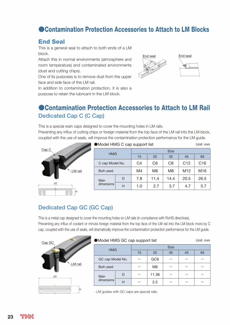
●Contamination Protection Accessories to Attach to LM Blocks
End SealThis is a general seal to attach to both ends of a LM
block.
Attach this in normal environments (atmosphere and
room temperature) and contaminated environments
(dust and cutting chips).
One of its purposes is to remove dust from the upper
face and side face of the LM rail.
In addition to contamination protection, it is also a
purpose to retain the lubricant in the LM block.
End sealEnd seal
●Contamination Protection Accessories to Attach to LM RailDedicated Cap C (C Cap)
This is a special resin caps designed to cover the mounting holes in LM rails.
Preventing any influx of cutting chips or foreign material from the top face of the LM rail into the LM block,
coupled with the use of seals, will improve the contamination protection performance for the LM guide.
Cap C
LM rail
φD
H
Dedicated Cap GC (GC Cap)
This is a metal cap designed to cover the mounting holes on LM rails (in compliance with RoHS directives).
Preventing any influx of coolant or minute foreign material from the top face of the LM rail into the LM block more by C
cap, coupled with the use of seals, will dramatically improve the contamination protection performance for the LM guide.
Cap GC
LM rail
φD
H
●Model HMG C cap support list Unit: mm
HMGSize
15 25 35 45 65
C cap Model No. C4 C6 C8 C12 C16
Bolt used M4 M6 M8 M12 M16
Main dimensions
D 7.8 11.4 14.4 20.5 26.5
H 1.0 2.7 3.7 4.7 5.7
●Model HMG GC cap support list Unit: mm
HMGSize
15 25 35 45 65
GC cap Model No. - GC6 - - -
Bolt used - M6 - - -
Main dimensions
D - 11.36 - - -
H - 2.5 - - -
- LM guides with GC caps are special rails.
23
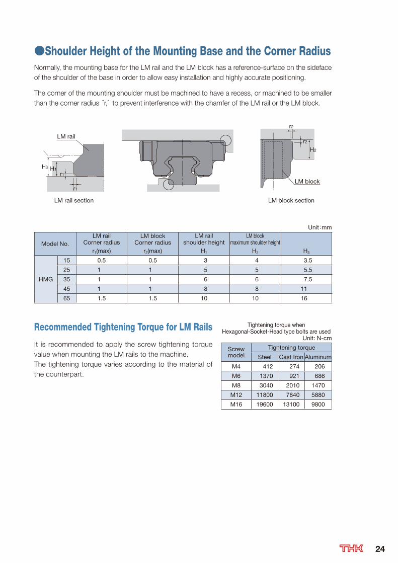
●Shoulder Height of the Mounting Base and the Corner RadiusNormally, the mounting base for the LM rail and the LM block has a reference-surface on the sideface
of the shoulder of the base in order to allow easy installation and highly accurate positioning.
The corner of the mounting shoulder must be machined to have a recess, or machined to be smaller
than the corner radius “r,” to prevent interference with the chamfer of the LM rail or the LM block.
LM rail section
LM rail
LM block
LM block section
H1r1
r2
r2
r1
H2
H3
Unit:mm
Model No.LM rail
Corner radiusLM block
Corner radiusLM rail
shoulder heightLM block
maximum shoulder heightr1(max) r2(max) H1 H2 H3
HMG
15 0.5 0.5 3 4 3.5
25 1 1 5 5 5.5
35 1 1 6 6 7.5
45 1 1 8 8 11
65 1.5 1.5 10 10 16
Recommended Tightening Torque for LM Rails
It is recommended to apply the screw tightening torque
value when mounting the LM rails to the machine.
The tightening torque varies according to the material of
the counterpart.
Tightening torque when Hexagonal-Socket-Head type bolts are used
Unit: N-cm
Screw model
Tightening torque
Steel Cast Iron Aluminum
M4 412 274 206
M6 1370 921 686
M8 3040 2010 1470
M12 11800 7840 5880
M16 19600 13100 9800
24

●Examples of Table MechanismsThe Straight-Curved Guide HMG requires a rotating mechanism or a slide mechanism for the
table to rotate the curved sections when 2 or more rails are used or when 2 or more LM blocks
are connected on a single rail. Refer to Fig.1 for examples of such mechanisms.
Fig.1 Examples of Table Mechanisms
Fig.2 shows examples of designing a table
when units are used on multiple axes. HMG
requires a rotating mechanism and a slide
mechanism since the table is decentered
when an LM block transits from a straight
section to a curved section. The amount of
decentering differs according to the radius
of the curved section and the LM block
span. Therefore, it is necessary to design the
system in accordance with the corresponding
specifications.
Fig.3 shows detail drawings of the slide and
rotating mechanisms. In the figure, LM Guides
are used in the slide mechanism and Cross-
Roller Rings in the rotating mechanism to
achieve smooth sliding and rotating motions.
For driving the Straight-Curved Guide, belt
drives and chain drives are available.
Slide
dista
nce
of the
table
Rotation Rotation
Rotation + slide
Rotation + slideRotation + slide Rotation + slide
Curved section
Straight section
Cross-roller ringLM Guide
Cross-roller ringLM GuideRotation + slide Rotation
RotationRotation + slide
Fig.2 Fig.3
Two LM blocks on single rail
: Rotating mechanism
Three or more LM blocks on single rail
: Rotating mechanism and slide mechanism
Two LM blocks on 2 rails
Four LM blocks on 2 rails(1) (2)
Six or more LM blocks on 2 rails
25

●Precautions on Using the LM Guide[Handling](1) Please use at least two people to move any product weighing 20 kg or more, or use a dolly or
another conveyance. Doing so may cause injury or damage.
(2) Do not disassemble the parts. This will result in loss of functionality.
(3) Tilting an LM block or LM rail may cause them to fall by their own weight.
(4) Take care not to drop or strike the LM Guide. Doing so may cause injury or damage. Giving an
impact to it could also cause damage to its function even if the product looks intact.
(5) Do not remove the LM block from the LM rail during setup.
(6) Do not insert hands or fingers into the mounting holes on the LM rail, as they could get caught
between the rail and the LM block, resulting in injury.
(7) To ensure personal safety, wear gloves and protective footwear when handling this product.
[Precautions on Use](1) Prevent foreign material, such as cutting chips or coolant, from entering the product. Failure to
do so may cause damage.
(2) If the product is used in an environment where cutting chips, coolant, corrosive solvents,
water, etc., may enter the product, use bellows, covers, etc., to prevent them from entering
the product.
(3) Do not use this product if the external temperature exceeds 80℃. Unless the unit is specially
designed to be heat-resistant, exposure to such temperatures may deform or damage plastic
and rubber parts.
(4) If foreign material such as cutting chips adheres to the product, replenish the lubricant after
cleaning the product.
(5) Micro-strokes tend to obstruct oil film to form on the raceway in contact with the rolling
element, and may lead to fretting corrosion. Take consideration using grease offering excellent
fretting prevention. It is also recommended that a stroke movement corresponding to the
length of the LM block be made on a regular basis to make sure oil film is formed between the
raceway and rolling element.
(6) Do not use undue force when fitting parts (pin, key, etc.) to the product. This may generate
permanent deformation on the raceway, leading to loss of functionality.
(7) If, for operational reasons, it becomes absolutely necessary to remove the LM block from the
LM rail and reattach it, a special mounting jig must be used for this purpose. (The mounting jig
is not included with standard versions of the product. To obtain one, please contact THK.)
(8) Position the mounting jig so that one end abuts the end of the LM rail. When the rail and the
jig are exactly aligned, the LM block can be loaded onto the rail.
(9) Take care to keep the LM block straight. Loading the block at an angle can introduce foreign
matter, damage internal components, or cause balls to fall out.
(10) The LM block must contain all its internal rolling elements (balls) when mounted on the LM
rail. Using a block with any balls removed may result in premature damage.
(11) Please contact THK if any balls fall out of the LM block; do not use the block if any balls are
missing.
(12) If the end plate is damaged due to an accident, etc., balls may fall out or the LM block may
become detached from the LM rail and drop. If the LM Guide will be used hanging upside
down, take preventive measures such as adding a safety mechanism to prevent falls.
(13) Insufficient rigidity or accuracy of mounting members causes the bearing load to
concentrate on one point and the bearing performance will drop significantly. Accordingly,
give sufficient consideration to the rigidity/accuracy of the housing and base and strength
of the fixing bolts. 26
(14) When removing the LM block from the LM rail and then replacing the block, an LM block
mounting/removing jig that facilitates such installation is available. Contact THK for details.
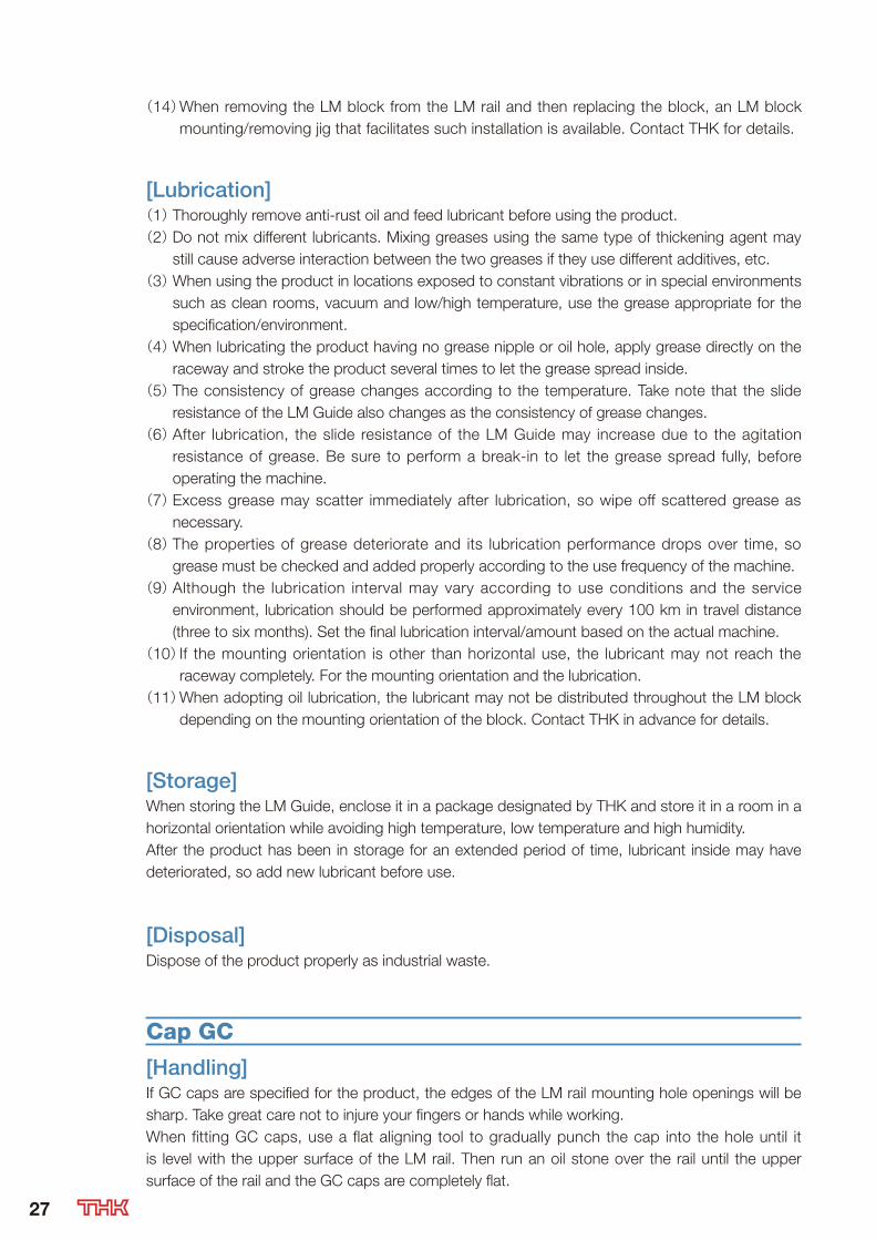
[Lubrication](1) Thoroughly remove anti-rust oil and feed lubricant before using the product.
(2) Do not mix different lubricants. Mixing greases using the same type of thickening agent may
still cause adverse interaction between the two greases if they use different additives, etc.
(3) When using the product in locations exposed to constant vibrations or in special environments
such as clean rooms, vacuum and low/high temperature, use the grease appropriate for the
specification/environment.
(4) When lubricating the product having no grease nipple or oil hole, apply grease directly on the
raceway and stroke the product several times to let the grease spread inside.
(5) The consistency of grease changes according to the temperature. Take note that the slide
resistance of the LM Guide also changes as the consistency of grease changes.
(6) After lubrication, the slide resistance of the LM Guide may increase due to the agitation
resistance of grease. Be sure to perform a break-in to let the grease spread fully, before
operating the machine.
(7) Excess grease may scatter immediately after lubrication, so wipe off scattered grease as
necessary.
(8) The properties of grease deteriorate and its lubrication performance drops over time, so
grease must be checked and added properly according to the use frequency of the machine.
(9) Although the lubrication interval may vary according to use conditions and the service
environment, lubrication should be performed approximately every 100 km in travel distance
(three to six months). Set the final lubrication interval/amount based on the actual machine.
(10) If the mounting orientation is other than horizontal use, the lubricant may not reach the
raceway completely. For the mounting orientation and the lubrication.
(11) When adopting oil lubrication, the lubricant may not be distributed throughout the LM block
depending on the mounting orientation of the block. Contact THK in advance for details.
[Storage]When storing the LM Guide, enclose it in a package designated by THK and store it in a room in a
horizontal orientation while avoiding high temperature, low temperature and high humidity.
After the product has been in storage for an extended period of time, lubricant inside may have
deteriorated, so add new lubricant before use.
[Disposal]Dispose of the product properly as industrial waste.
Cap GC
[Handling]If GC caps are specified for the product, the edges of the LM rail mounting hole openings will be
sharp. Take great care not to injure your fingers or hands while working.
When fitting GC caps, use a flat aligning tool to gradually punch the cap into the hole until it
is level with the upper surface of the LM rail. Then run an oil stone over the rail until the upper
surface of the rail and the GC caps are completely flat.
27
LIMITED WARRANTY
DISCLAIMER
LIMITED WARRANTY AND LIMITATION OF LIABILITY: THK CO. LTD., FOR ITSELF AND ITS RELATED COMPANIES AND SUBSIDIARIES (HEREINAFTER DESCRIBED COLLECTIVELY AS “THK” ) WARRANTS THAT ALL THK PRODUCTS SOLD WILL BE FREE OF DEFECTS IN MATERIALS AND WORKMANSHIP FOR A PERIOD OF TWELVE (12) MONTHS FROM DATE OF DELIVERY. THE FOREGOING TWELVE (12) MONTH WARRANTY SHALL NOT BE EXTENDED OR CHANGED BY THK FURNISHING ANY REPLACEMENTS, ADDITIONS, ATTACHMENTS, ACCESSORIES OR REPAIRS TO THE PRODUCT SUBSEQUENT TO THE DATE OF DELIVERY OR ACCEPTANCE. THE FOREGOING WARRANTY IS THE SOLE AND EXCLUSIVE WARRANTY OF THK REGARDING THE PRODUCT.DISCLAIMER OF OTHER WARRANTIES: OTHER THAN THE FOREGOING WARRANTY, THERE ARE NO EXPRESS OR IMPLIED WARRANTIES OR ANY AFFIRMATIONS OF FACT OR PROMISES BY THK WITH RESPECT TO THE PRODUCT. THK DISCLAIMS ANY WARRANTIES, EXPRESS, IMPLIED OR STATUTORY, NOT SPECIFICALLY SET FORTH ABOVE. WITHOUT LIMITING THE GENERALITY OF THE FOREGOING, THK EXPRESSLY DISCLAIMS ANY IMPLIED WARRANTIES OF MERCHANTABILITY, FITNESS FOR ANY PARTICULAR PURPOSE, INFRINGEMENT OR ANY REPRESENTATIONS OF FACT OR QUALITY NOT EXPRESSLY SET FORTH HEREIN. LIMITATION OF LIABILITY AND REMEDIES: THK'S SOLE RESPONSIBILITY AND LIABILITY INCURRED AS A RESULT OF THE SALE AND/OR USE OF THE PRODUCT, AND THE PURCHASER'S EXCLUSIVE REMEDY AGAINST THK UNDER ANY WARRANTY SHALL BE LIMITED TO THE REPAIR OR REPLACEMENT, AT THK'S OPTION, OF PRODUCT COMPONENTS NOT CONFORMING TO THE WARRANTY. THE TOTAL LIABILITY OF THK SHALL IN NO EVENT EXCEED THE AMOUNT ACTUALLY PAID TO THK BY PURCHASER WITH RESPECT TO THE PRODUCT. THIS LIMITATION OF REMEDY IS INTENDED BY THE PARTIES TO SURVIVE EVEN IF THE REMEDY IS CLAIMED TO HAVE FAILED OF ITS ESSENTIAL PURPOSE. PURCHASER'S FULL AND COMPLETE PERFORMANCE OF ALL OBLIGATIONS OF PURCHASER RECITED IN THIS AGREEMENT IS A CONDITION PRECEDENT TO THK'S WARRANTY OBLIGATIONS AND LIABILITIES HEREIN. PURCHASER'S DAMAGES AND LIMITATIONS: IN NO EVENT SHALL THK BE LIABLE TO PURCHASER, ITS ASSIGNS OR AGENTS, FOR ECONOMIC LOSS, INCIDENTAL OR CONSEQUENTIAL DAMAGES, IN CONTRACT OR IN TORT, INCLUDING BUT NOT LIMITED TO, ANY DAMAGES FOR LOST PROFITS, DOWN-TIME, LOST PRODUCTION, FAILURE TO MEET PURCHASER'S SALES CONTRACTS, OR DEFECTS IN PURCHASER'S MATERIALS OR WORKMANSHIP ARISING DIRECTLY OR INDIRECTLY FROM THE USE OF THE PRODUCT.
This Catalog provides basic information relating to THK linear motion and related products. The Catalog, including all information, charts, formulas, factors, accuracy standards, tolerances and application recommendations contained herein, is only a starting point for the customer’ s selection of appropriate products, and may not apply in all intended applications. The Catalog is not a substitute for a proper application analysis conducted by an experienced, knowledgeable design engineer. Product selection should be based upon your specific application needs and conditions, which will vary greatly depending on many factors. No specific product application should be based solely on the information contained in this Catalog. All purchases of THK Products are subject to the limited warranty offered by THK Co., Ltd, for itself and on behalf of its related companies and subsidiaries. Customers should confirm independently that a contemplated application is safe, appropriate and effective."All trademarks used in this Catalog are registered trademarks in the Country of Japan. If there is any question as to the validity of such trademarks outside of Japan, an inquiry should be made in that particular country."
28

Technical Support Site
http://www.thk.com/ or
Top page of the Global site Technical Support Site
The THK Technical Support Site lets you access product information and technical support online.You will also find a search feature for locating desired products and a calculation feature for calculating service life. 2D-CAD and 3D-CAD data are also downloadable.
Product Information
Search by model number or description.
Also contains detailed product specifications according to
model number.
Technical Information
Contains technical information, from application examples
to research papers.(* To use this service, you must log in first.)
Technical Calculation
Rated life (life time) can be calculated simply by entering
model number, application criteria, etc.(* To use this service, you must log in first.)
CAD Data
You can acquire 2D-CAD data (DXF files) on approximately
4,000 items, or 3D-CAD data according to specifications
from rail lengths to installation of option items.(* To use this service, you must log in first.)
Catalog Information
Order any of a variety of catalogs. You can also view in PDF
format.(* To use this service, you must log in first.)
FAQ
Contains frequently asked questions.
SearchTHK
http://www.thk.com/
https://tech.thk.com/
29
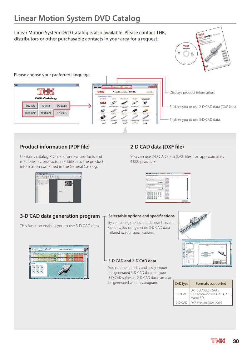
Linear Motion System DVD Catalog
Product information (PDF file)
Contains catalog PDF data for new products and
mechatronic products, in addition to the product
information contained in the General Catalog.
2-D CAD data (DXF file)
You can use 2-D CAD data (DXF files) for approximately
4,000 products.
3-D CAD data generation program
This function enables you to use 3-D CAD data.
Selectable options and specifications
By combining product model numbers and
options, you can generate 3-D CAD data
tailored to your specifications.
3-D CAD and 2-D CAD data
You can then quickly and easily import
the generated 3-D CAD data into your
3-D CAD software. 2-D CAD data can also
be generated with this program.
Linear Motion System DVD Catalog is also available. Please contact THK, distributors or other purchasable contacts in your area for a request.
Please choose your preferred language.
CAD type Formats supported
3-D CAD
2-D CAD
DXF 3D / IGES / SAT /
STEP Solidworks 2013, 2014, 2015,
Macro 3D
DXF Version 2004-2015
Displays product information.
Enables you to use 2-D CAD data (DXF files).
Enables you to use 3-D CAD data.
30

The photo may differ slightly in appearance from the actual product.The appearance and specifications of the product are subject to change without notice. Contact THK before placing an order.Although great care has been taken in the production of this catalog, THK will not take any responsibility for damage resulting from typographical errors or omissions.For the export of our products or technologies and for the sale for exports, THK in principle complies with the foreign exchange law and the Foreign Exchange and Foreign Trade Control Law as well as other relevant laws.For export of THK products as single items, contact THK in advance.
All rights reserved
“LM GUIDE” are registered trademarks of THK CO., LTD.
R Guide Model HCR / Straight-Curved Guide Model HMG
Head Office 3-11-6 Nishigotanda, Shinagawa-ku, Tokyo 141-8503 JAPANInternational Sales Department Phone:+81-3-5434-0351 Fax:+81-3-5434-0353
NORTH AMERICATHK America,Inc.
HEADQUARTERSPhone:+1-847-310-1111 Fax:+1-847-310-1271CHICAGO OFFICEPhone:+1-847-310-1111 Fax:+1-847-310-1182NORTH EAST OFFICE Phone:+1-631-244-1565 Fax:+1-631-244-1565ATLANTA OFFICEPhone:+1-770-840-7990 Fax:+1-770-840-7897LOS ANGELES OFFICEPhone:+1-949-955-3145 Fax:+1-949-955-3149SAN FRANCISCO OFFICEPhone:+1-925-455-8948 Fax:+1-925-455-8965DETROIT OFFICEPhone:+1-248-858-9330 Fax:+1-248-858-9455TORONTO OFFICEPhone:+1-905-820-7800 Fax:+1-905-820-7811
SOUTH AMERICATHK BRAZIL INDUSTRIA E COMERCIO LTDA.
Phone:+55-11-3767-0100 Fax:+55-11-3767-0101EUROPETHK GmbH
DÜSSELDORF OFFICEPhone:+49-2102-7425-0 Fax:+49-2102-7425-299
EUROPEAN HEADQUARTERSPhone:+49-2102-7425-555 Fax:+49-2102-7425-556
U.K. OFFICEPhone:+44-1384-47-1550 Fax:+44-1384-47-1551
Global site : http://www.thk.com/
©THK CO., LTD. 201512000 E27 Printed in Japan
STUTTGART OFFICEPhone:+49-7141-4988-500 Fax:+49-7141-4988-888
TURKEY OFFICEPhone:+90-216-362-4050 Fax:+90-216-569-7150
MOSCOW OFFICEPhone:+7-495-649-80-47 Fax:+7-495-649-80-44
SWEDEN OFFICEPhone:+46-8-445-7630 Fax:+46-8-445-7639 AUSTRIA OFFICEPhone:+43-7229-51400 Fax:+43-7229-51400-79SPAIN OFFICEPhone:+34-93-652-5740 Fax:+34-93-652-5746
EINDHOVEN OFFICETHK Europe B.V.
THK France S.A.S.Phone:+31-040-290-9500 Fax:+31-040-290-9599
PARIS OFFICEPhone:+33-1-7425-3800 Fax:+33-1-7425-3799
PRAGUE OFFICEPhone:+420-2-41025-100 Fax:+420-2-41025-199
SHANGHAI OFFICEPhone:+86-21-6219-3000 Fax:+86-21-6219-9890BEIJING OFFICEPhone:+86-10-8441-7277 Fax:+86-10-6590-3557CHENGDU OFFICEPhone:+86-28-8526-8025 Fax:+86-28-8525-6357GUANGZHOU OFFICEPhone:+86-20-8523-8418 Fax:+86-20-3801-0456
CHINATHK (CHINA) CO.,LTD.
HEADQUARTERSPhone:+86-411-8733-7111 Fax:+86-411-8733-7000
TAIWANTHK TAIWAN CO.,LTD.
TAIPEI HEAD OFFICEPhone:+886-2-2888-3818TAICHUNG OFFICEPhone:+886-4-2359-1505 TAINAN OFFICEPhone:+886-6-289-7668
KOREASEOUL REPRESENTATIVE OFFICE
Phone:+82-2-3468-4351SINGAPORETHK LM System Pte. Ltd.
THK (SHANGHAI) CO.,LTD.Phone:+86-21-6275-5280 Fax:+86-21-6219-9890
Fax:+886-2-2888-3819
Fax:+886-4-2359-1506
THK India Pvt. Ltd.HEADQUARTERS & Bangalore BranchPhone:+91-80-2340-9934Pune BranchPhone:+91-20-4120-8742
Fax:+91-80-2340-9937
Chennai BranchPhone:+91-44-4042-3132Ahmedabad BranchPhone:+91-79-6134-4925Delhi BranchPhone:+91-12-4676-8695
Fax:+886-6-289-7669
Fax:+82-2-3468-4353
Fax:+65-6884-5550
INDIA
Phone:+65-6884-5500THAILANDTHK RHYTHM(THAILAND) CO., LTD. LM System Division
Bangkok BranchPhone:+66-2751-3001 Fax:+66-2751-3003
XIAN OFFICEPhone:+86-29-8834-1712 Fax:+86-29-8834-1710
ITALY OFFICEPhone:+39-02-9901-1801 Fax:+39-02-9901-1881
SHENZHEN OFFICEPhone:+86-755-2642-9587 Fax:+86-755-2642-9604


