

Utility model registration No. 1909119 LM Guide SR — High ... · PDF filean LM rail and...
21
Balls roll in four rows of a precisely-ground raceway on an LM rail and an LM block. The end plate attached to the LM block causes the trains of balls to circulate. As the balls are held in place by the retainer plate, they do not fall off if the LM block is removed from the rail. The low profile of the assembly and the high rigidity of the LM block combine to provide stable linear motion with a high degree of accuracy. A-174 Japanese Patent Nos. 1425810, 1661851, and 1692316 Utility model registration No. 1909119 LM Guide SR — High-Rigidity Radial Type Fig. 1 Construction of Model SR-W LM block End plate End seal LM rail Retainer plate Ball Construction and Features Side seal (optional) Grease nipple Cross section Compact and heavy-load-bearing Due to its low-profile, compact design and the 90° ball contact angle in respect to the radial direction, LM Guide SR is best suited for horizontal guideways. Simple establishment of mounting accuracy A self-adjusting type capable of compensating for errors in parallelism between two axes and levelness, SR ensures precision and smooth, lively linear motion. Low noise The guideway on the end plate installed at each end of the LM block ensures the smooth circulation of the trains of balls at turning corners. As a result, the rolling balls generate little noise. High durability Free from differential slip even under preload or uneven load, the balls roll smoothly. This results in high wear resistance and excellent long-term precision. Stainless steel type available Upon request, we can provide stainless steel LM blocks, rails, and balls. www.thk.ru BERG AB [email protected] Тел. (495)-727-22-72, ф. (495)-223-3071
Transcript of Utility model registration No. 1909119 LM Guide SR — High ... · PDF filean LM rail and...

Balls roll in four rows of a precisely-ground raceway onan LM rail and an LM block. The end plate attached tothe LM block causes the trains of balls to circulate. Asthe balls are held in place by the retainer plate, they do
not fall off if the LM block is removed from the rail.The low profile of the assembly and the high rigidity ofthe LM block combine to provide stable linear motionwith a high degree of accuracy.
A-174
Japanese Patent Nos. 1425810, 1661851, and 1692316Utility model registration No. 1909119
LM Guide SR — High-Rigidity Radial Type
Fig. 1 Construction of Model SR-W
LM block
End plate
End seal
LM rail
Retainer plate
Ball
Construction and Features
Side seal (optional)
Grease nipple
Cross section
Compact and heavy-load-bearingDue to its low-profile, compact design and the 90°ball contact angle in respect to the radial direction, LMGuide SR is best suited for horizontal guideways.
Simple establishment of mountingaccuracyA self-adjusting type capable of compensating forerrors in parallelism between two axes and levelness,SR ensures precision and smooth, lively linear motion.
Low noiseThe guideway on the end plate installed at each end ofthe LM block ensures the smooth circulation of thetrains of balls at turning corners. As a result, therolling balls generate little noise.
High durabilityFree from differential slip even under preload oruneven load, the balls roll smoothly. This results inhigh wear resistance and excellent long-term precision.
Stainless steel type availableUpon request, we can provide stainless steel LMblocks, rails, and balls.
www.thk.ru BERG AB [email protected] Тел. (495)-727-22-72, ф. (495)-223-3071

A-175
A-IV
Types and Features
Type SR-W Type SR-V
Low-profile, compact, and strong against radial loads.One of the representative models of the LM Guide.
Type SR-W modified by shortening the LM blocks;therefore space-saving
Type SR-TB Type SR-SB
Of the same height as type SR-W. The LM blocks canbe attached to a table from below.
Type SR-TB modified by shortening the LM blocks;therefore space-saving
www.thk.ru BERG AB [email protected] Тел. (495)-727-22-72, ф. (495)-223-3071
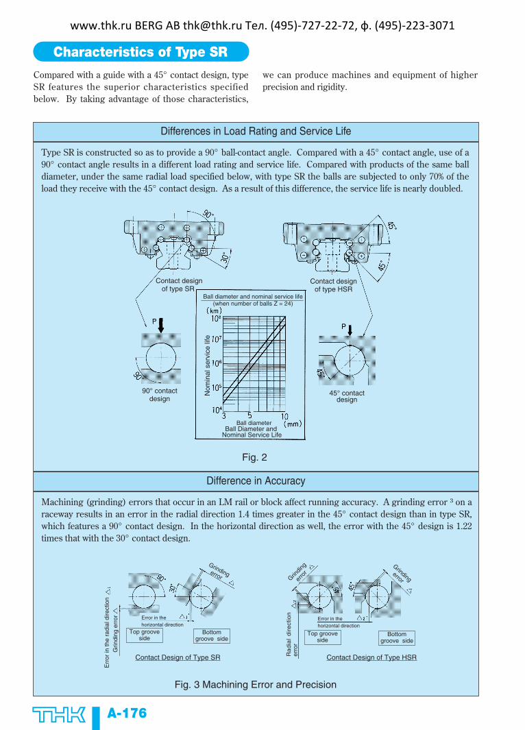
Compared with a guide with a 45° contact design, typeSR features the superior characteristics specifiedbelow. By taking advantage of those characteristics,
we can produce machines and equipment of higherprecision and rigidity.
A-176
Characteristics of Type SR
Differences in Load Rating and Service Life
Type SR is constructed so as to provide a 90° ball-contact angle. Compared with a 45° contact angle, use of a90° contact angle results in a different load rating and service life. Compared with products of the same balldiameter, under the same radial load specified below, with type SR the balls are subjected to only 70% of theload they receive with the 45° contact design. As a result of this difference, the service life is nearly doubled.
Difference in Accuracy
Machining (grinding) errors that occur in an LM rail or block affect running accuracy. A grinding error ³ on araceway results in an error in the radial direction 1.4 times greater in the 45° contact design than in type SR,which features a 90° contact design. In the horizontal direction as well, the error with the 45° design is 1.22times that with the 30° contact design.
Fig. 3 Machining Error and Precision
Fig. 2
Contact designof type SR
Contact designof type HSR
90° contactdesign
45° contactdesign
Ball diameter and nominal service life(when number of balls Z = 24)
Ball diameterBall Diameter and
Nominal Service Life
Nom
inal
ser
vice
life
Err
or in
the
radi
al d
irect
ion
Grin
ding
err
or
Top groove side
Top groove side
Bottom groove side
Bottom groove side
Error in thehorizontal direction
Grindingerror
Contact Design of Type SR Contact Design of Type HSR
Error in thehorizontal direction
Grindingerror Grin
ding
erro
r
Rad
ial
dire
ctio
ner
ror
www.thk.ru BERG AB [email protected] Тел. (495)-727-22-72, ф. (495)-223-3071

A-177
A-IV
Difference in Rigidity
The 90° contact design applied to type SR differs in rigidity from the 45° design.Under the same radial load P, the deflection in the radial direction with type SR is only 56% of that with the45° design. The diagrams below show the differences in radial load and deflection. Therefore, when it isnecessary to ensure rigidity in the radial direction, type SR has an advantage over other types.
Summary
As illustrated above, type SR is best suited for places where the radial load is the main load, radial rigidity isrequired, and it is necessary to ensure running accuracy in both the horizontal and vertical directions.
However, where a large reverse-radial or lateral load or a great moment is exerted, we recommend use of afour-way equal-load type such as HSR.
Fig. 4 Deflection under Radial Load
Fig. 5 Radial Load and Deflection
Def
lect
ion
Def
lect
ion
in th
e ra
dial
dire
ctio
n
Deflec
tion
Def
lect
ion
in th
e ra
dial
dire
ctio
n
Applied load (N)
Contact angle: 45°
Contact angle: 90°
Def
lect
ion
Load and deflection (Da = 6.35 mm) for different contact angles
(Deflection per ball)
www.thk.ru BERG AB [email protected] Тел. (495)-727-22-72, ф. (495)-223-3071

A-178
Load Rating and Permissible Moment in Various Directions
Load rating
Fig. 6
Radial direction
Lateraldirections
Reverse-radial direction
Lateraldirections
Type SR can bear loads in all four directions: radial,reverse-radial, and the two lateral directions.
The basic load ratings of type SR is in the radialdirection indicated in Fig. 6. The values are presentedin the corresponding dimension tables. Values in thereverse-radial and lateral directions can be obtainedfrom Table 1.
Equivalent loadAn equivalent load for type SR when reverse-radial andlateral loads are exerted on its LM blocksimultaneously can be obtained using the followingequation:
PE = X•P
L+ Y•P
T
whereP
E: equivalent load (N)
- In the reverse-radial direction- In the lateral directions
PL
: reverse-radial load (N)P
T: lateral load (N)
X and Y : equivalent factor (see Table 2)
SR
15 ∼ 70
SR
85 ∼ 150
C
CL=0.62C
CT=0.56C
C
CL=0.78C
CT=0.48C
CO
COL=0.50CO
COT=0.43CO
CO
COL=0.71CO
COT=0.35CO
Direction Basic dynamic-load rating
Basic static-load rating
Radial direction
Reverse-radial direction
Radial direction
Reverse-radial direction
Lateral directions
Lateral directions
Table 1 Type SR Basic Load Ratings in Various Directions
Model No.
PE X Y
1
0.866
1
0.5
SR
15 ∼ 70
SR
85 ∼ 150
1.155
1
2
1
Table 2 Type-SR Equivalent Factor
Model No.
Equivalent load in the lateral directions
Equivalent load in the reverse-radial direction
Equivalent load in the reverse-radial direction
Equivalent load in the lateral directions
www.thk.ru BERG AB [email protected] Тел. (495)-727-22-72, ф. (495)-223-3071
A-179
A-IV
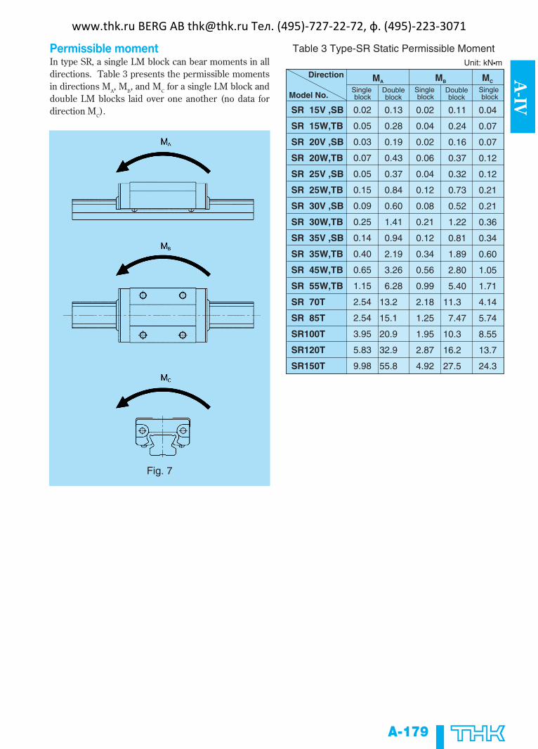
Permissible momentIn type SR, a single LM block can bear moments in alldirections. Table 3 presents the permissible momentsin directions M
A, M
B, and M
Cfor a single LM block and
double LM blocks laid over one another (no data fordirection M
C).
Fig. 7
0.02
0.05
0.03
0.07
0.05
0.15
0.09
0.25
0.14
0.40
0.65
1.15
2.54
2.54
3.95
5.83
9.98
SR 15V ,SB
SR 15W,TB
SR 20V ,SB
SR 20W,TB
SR 25V ,SB
SR 25W,TB
SR 30V ,SB
SR 30W,TB
SR 35V ,SB
SR 35W,TB
SR 45W,TB
SR 55W,TB
SR 70T
SR 85T
SR100T
SR120T
SR150T
0.13
0.28
0.19
0.43
0.37
0.84
0.60
1.41
0.94
2.19
3.26
6.28
13.2
15.1
20.9
32.9
55.8
0.02
0.04
0.02
0.06
0.04
0.12
0.08
0.21
0.12
0.34
0.56
0.99
2.18
1.25
1.95
2.87
4.92
0.11
0.24
0.16
0.37
0.32
0.73
0.52
1.22
0.81
1.89
2.80
5.40
11.3
7.47
10.3
16.2
27.5
0.04
0.07
0.07
0.12
0.12
0.21
0.21
0.36
0.34
0.60
1.05
1.71
4.14
5.74
8.55
13.7
24.3
MA MB MC
Unit: kN•m
Table 3 Type-SR Static Permissible Moment
Single block
Single block
Single block
Doubleblock
DoubleblockModel No.
Direction
www.thk.ru BERG AB [email protected] Тел. (495)-727-22-72, ф. (495)-223-3071

A-180
Model-number coding
SR30 W 2 UU C0 M + 1200L P M – II
No. of axes
LM-rail material (stainless steel in this example)
Accuracy grade
LM-rail length (in mm)
LM-block material (stainless steel in this example)
Radial clearance
No. of LM blocks combined on a single axis
Classification of the LM block
Model No.
Provision of end seals (attached to both end faces in this example; for end seal + side seal, this becomes “SS”)
Note: This coding is based on the assumption of one set of code for a one-axis unit. (A configuration of two axes installed in parallel is given at least two sets of code.)
Radial clearance
Table 4 presents the radial clearances of types SR.
SR 15
SR 20
SR 25
SR 30
SR 35
SR 45
SR 55
SR 70
SR 85
SR 100
SR 120
SR 150
Unit : µm
– 4 ∼ + 2
– 5 ∼ + 2
– 6 ∼ + 3
– 7 ∼ + 4
– 8 ∼ + 4
– 10 ∼ + 5
– 12 ∼ + 5
– 14 ∼ + 7
– 20 ∼ + 9
– 22 ∼ + 10
– 25 ∼ + 12
– 29 ∼ + 14
– 10 ∼ – 4
– 12 ∼ – 5
– 15 ∼ – 6
– 18 ∼ – 7
– 20 ∼ – 8
– 24 ∼ – 10
– 28 ∼ – 12
– 32 ∼ – 14
– 46 ∼ – 20
– 52 ∼ – 22
– 57 ∼ – 25
– 69 ∼ – 29
– 17 ∼ – 12
– 21 ∼ – 15
– 26 ∼ – 18
– 31 ∼ – 20
– 36 ∼ – 24
– 45 ∼ – 28
– 50 ∼ – 32
– 70 ∼ – 46
– 78 ∼ – 52
– 87 ∼ – 57
–104 ∼ – 69
Table 4 Type SR Radial Clearances
Model No.
Clearance symbol
C1
NormalUnder a light
preload
No symbol
C0
Medium preload
Accuracy StandardsThe accuracy of type SR is divided into five grades,normal, high, precision, super-precision, and ultra-precision, in accordance with the model numbersshown in Table 5.
Fig. 9 Relationship Between LM-Rail Length and Running Parallelism
Fig. 8
Normal grade
LM-Rail length (mm)
www.thk.ru BERG AB [email protected] Тел. (495)-727-22-72, ф. (495)-223-3071

A-181
A-IV
Tolerance for the height M difference among LM blocks
SR 15SR 20
SR 25SR 30SR 35
±0.03
0.01
±0.03
0.01
±0.1
0.02
±0.1
0.02
±0.04
0.015
±0.04
0.015
±0.1
0.02
±0.1
0.03
SR 45SR 55
±0.05
0.015
±0.05
0.02
±0.1
0.03
±0.1
0.03
SR 70SR 85SR 100SR 120SR 150
±0.07
0.02
±0.07
0.025
±0.1
0.03
±0.1
0.03
0.006
0.006
0-0.03
0-0.03
0.007
0.007
0-0.04
0-0.04
0.007
0.01
0-0.05
0-0.05
0.01
0.015
0-0.07
0-0.07
0.004
0.004
0-0.015
0
-0.015
0.005
0.005
0-0.02
0-0.02
0.005
0.007
0-0.03
0-0.03
0.007
0.010
0-0.05
0-0.05
0.003
0.003
0-0.008
0-0.008
0.003
0.003
0-0.01
0-0.01
0.003
0.005
0-0.02
0-0.02
0.005
0.007
0-0.03
0-0.03
Unit : mmTable 5 Type SR Accuracy Standard
Model No.Accuracy standard
Item
High
H
Normal
No symbol
Precision
P
SP
UP
Super-precision Ultra-precision
Tolerance for height M
Tolerance for height M
Tolerance for the height M difference among LM blocksTolerance for rail-to-block lateral distance W2
Tolerance for rail-to-block lateral distance W2
Tolerance for rail-to-block lateral distance W2 difference among LM blocks
Tolerance for rail-to-block lateral distance W2 difference among LM blocks
Running Parallelism ofsurface C with surface A
Running parallelism of surface D with surface B
Running parallelism of surface D with surface B
Running Parallelism ofsurface C with surface A
C (as per Fig. 9)
D (as per Fig. 9)
Tolerance for height M
Tolerance for height M
C (as per Fig. 9)
D (as per Fig. 9)
D (as per Fig. 9)
C (as per Fig. 9)
Tolerance for the height M difference among LM blocks
Tolerance for the height M difference among LM blocks
Tolerance for rail-to-block lateral distance W2
Tolerance for rail-to-block lateral distance W2
Tolerance for rail-to-block lateral distance W2 difference among LM blocks
Tolerance for rail-to-block lateral distance W2 difference among LM blocks
Running Parallelism ofsurface C with surface A
Running Parallelism ofsurface C with surface A
Running parallelism of surface D with surface B
Running parallelism of surface D with surface B D (as per Fig. 9)
C (as per Fig. 9)
www.thk.ru BERG AB [email protected] Тел. (495)-727-22-72, ф. (495)-223-3071
A-182
Contamination Protection
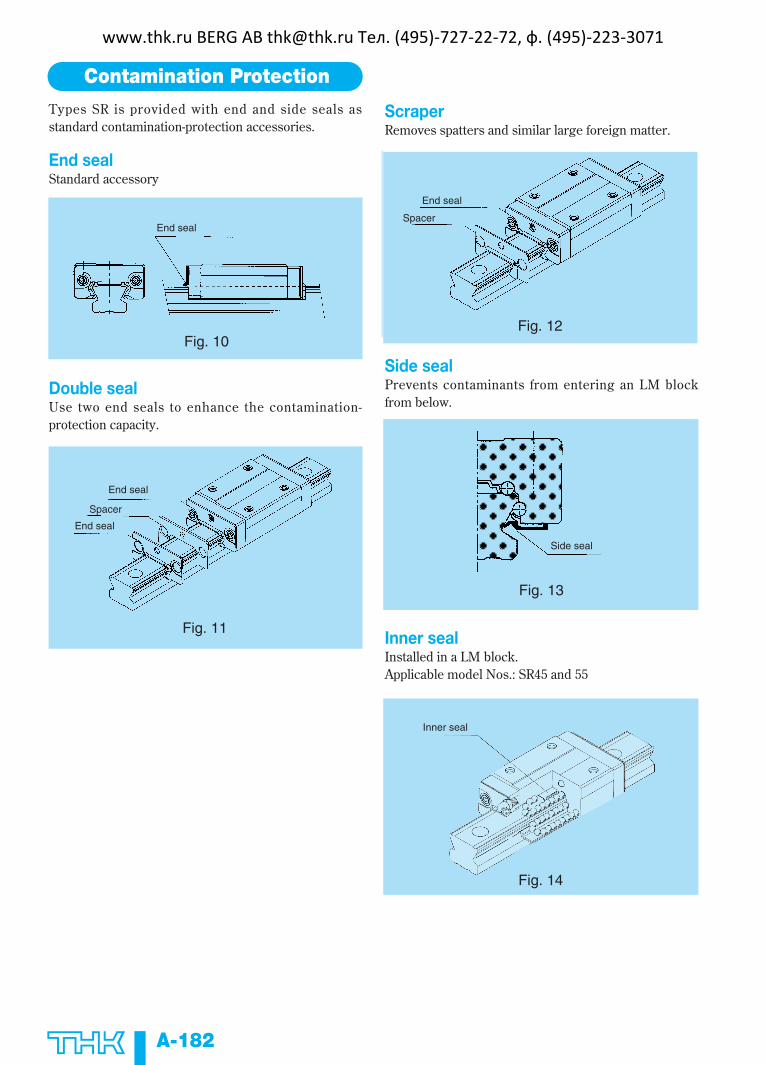
Types SR is provided with end and side seals asstandard contamination-protection accessories.
End sealStandard accessory
Double sealUse two end seals to enhance the contamination-protection capacity.
Fig. 10
End seal
Fig. 11
End seal
Spacer
End seal
ScraperRemoves spatters and similar large foreign matter.
Side sealPrevents contaminants from entering an LM blockfrom below.
Inner sealInstalled in a LM block.Applicable model Nos.: SR45 and 55
Fig. 12
End seal
Spacer
Fig. 13
Side seal
Fig. 14
Inner seal
www.thk.ru BERG AB [email protected] Тел. (495)-727-22-72, ф. (495)-223-3071

Contamination-protection-accessorysymbolWhere a contamination accessory is required, specifyso using the symbols shown below.
Some models do not accept contamination-protectionaccessories. Confirm which parts are applicable byreferring to Table 8.
Attaching a contamination-protection accessory to anLM block changes the block overall length. Add todimension L the increment specified in thecorresponding dimension table.
Seal resistance valueFor the maximum value of seal resistance of seals typeSR...UU per LM block, in which grease is applied, seeTable 7.
A-183
A-IV
UU
SS
ZZ
DD
KK
LL
RR
Table 6
Contamination-protection accessory Symbol
End seal (on both end faces)
End seal + side seal + scraper
Double seals + side seal + scraper
Double seals + side seal
End seal + side seal
End seal (low seal resistance)
LL seal + side seal
SR 15
SR 20
SR 25
SR 30
SR 35
SR 45
SR 55
SR 70
SR 85
SR 100
SR 120
SR 150
2.5
3.4
4.4
8.8
11.8
12.7
15.7
19.6
-
-
-
-
Model No. Seal resistance value
Unit : N
Table 7 Maximum Resistance Value of Seals to Type SR
SR 15
SR 20
SR 25
SR 30
SR 35
SR 45
SR 55
SR 70
SR 85
SR100
SR120
SR150
Ο
Ο
Ο
Ο
Ο
Ο
Ο
Ο
Ο
ΟΟ
-5.0
-6.3
-7.0
-7.0
-7.0
-8.0
-8.0
-7.4
-8.0
-8.0
-9.0
-9.0
Ο
Ο
Ο
Ο
Ο
Ο
Ο
Ο
Ο
Ο
ΟΟ
Ο
Ο
Ο
Ο
Ο
Ο
Ο
Ο
Ο
Ο
ΟΟ
Ο
Ο
Ο
Ο
Ο
Ο
Ο
Ο
×
×
××
5.2
6.3
7.6
7.6
7.6
8.6
8.6
6.8
∆
∆
Ο
Ο
Ο
Ο
Ο
Ο
×
×
××
1.4
4.1
4.4
2.6
2.6
3.4
3.4
3.8
∆
∆
Ο
Ο
Ο
Ο
Ο
Ο
×
×
××
6.6
10.7
12.0
10.2
10.2
12.0
12.0
11.0
Ο
Ο
Ο
×
×
×
×
×
×
×
××
Ο
Ο
Ο
×
×
×
×
×
×
×
××
UU SS DD ZZ KK LL RRModel. No.
Note: Ο = Applicable
× = Inapplicable
∆ = Applicable, but a grease nipple cannot be attached; contact us
Table 8 Applicability of Seals to Type SR, and the Increment to Be Added to the Block Overall Length
Unit : mm
No symbol
www.thk.ru BERG AB [email protected] Тел. (495)-727-22-72, ф. (495)-223-3071

A-184
Dedicated Bellows JS for LM-Guide Type SRShown below are the dimensions of dedicated bellows JS for type SR. When ordering the bellows, specify therelevant model number shown in the table below.
51
58
71
76
84
95
108
144
JS15
JS20
JS25
JS30
JS35
JS45
JS55
JS70
24
26
33
37.5
39
47.5
55.5
67
26
30
38
37.5
39
47.5
55.5
67
15
15
20
20
20
20
25
30
22
25
29
42
44
60
70
90
3.4
4.2
5
5
6.5
8
10
13
12
14
22
24
34
17
20
27
28
35
8
6
6
6
7
5
4
7
3
1.5
8.5
8
11.5
8
7
5
4
9
0.5
1
5
5
7
7
7
7
9
10
SR15
SR20
SR25
SR30
SR35
SR45
SR55
SR70
M3×0.5×16
M3×0.5×16
M3×0.5×16
M4×0.7×18
M5×0.8×10
M5×0.8×10
M6×12
M6×12
W H H1 P b1 t1 b2 t2 t3 t4 a W/Vtype
bTB/SBtype
ALmaxLmin
Unit : mm
Applicable LM-Guide
modelMounting
bolt
Model No.
Boundary dimensions
Note 1: The expansion ratios in installation directionsother than horizontal, e.g., vertical and wall-hung, differ from those specified in this table(guidelines: A – 1.5). When ordering bellows,please specify your installation direction.
Note 2: If bellows are attached to both ends of an LMblock, a grease nipple cannot be installedthere. In such a case, contact us.
Model-number coding
JS55 - 60/540
Model No. (bellows for type SR55 in this example)
Bellows dimensions
length when compressed
length when expanded( )
Lmin = S: stroke length in (mm)
Lmax = Lmin • A A: expansion ratio
S(A - 1)
Note: A bellows length can be calculated as shown below.
www.thk.ru BERG AB [email protected] Тел. (495)-727-22-72, ф. (495)-223-3071
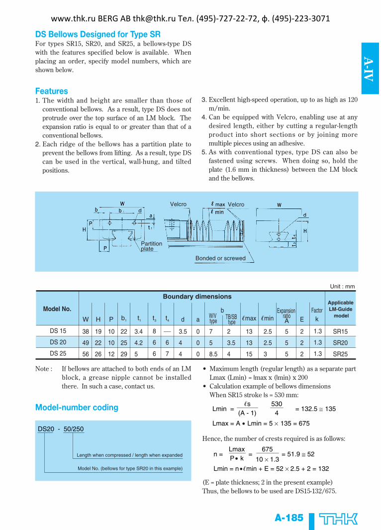
DS Bellows Designed for Type SRFor types SR15, SR20, and SR25, a bellows-type DSwith the features specified below is available. Whenplacing an order, specify model numbers, which areshown below.
Features1. The width and height are smaller than those of
conventional bellows. As a result, type DS does notprotrude over the top surface of an LM block. Theexpansion ratio is equal to or greater than that of aconventional bellows.
2. Each ridge of the bellows has a partition plate toprevent the bellows from lifting. As a result, type DScan be used in the vertical, wall-hung, and tiltedpositions.
3. Excellent high-speed operation, up to as high as 120m/min.
4. Can be equipped with Velcro, enabling use at anydesired length, either by cutting a regular-lengthproduct into short sections or by joining moremultiple pieces using an adhesive.
5. As with conventional types, type DS can also befastened using screws. When doing so, hold theplate (1.6 mm in thickness) between the LM blockand the bellows.
A-185
A-IV
DS 15
DS 20
DS 25
Unit : mm
7
5
8.5
38
49
56
19
22
26
10
10
12
22
25
29
3.4
4.2
5
8
6
6
6
7
3.5
4
4
0
0
0
2
3.5
4
13
13
15
2.5
2.5
3
5
5
5
2
2
2
1.3
1.3
1.3
SR15
SR20
SR25
W H P b1 t1 dt3 t4TB/SB
typeab
W/V type �max �min
Expansion ratioA
FactorkE
Applicable LM-Guide
modelModel No.
Boundary dimensions
• Maximum length (regular length) as a separate partLmax (Lmin) = lmax x (lmin) x 200
• Calculation example of bellows dimensionsWhen SR15 stroke ls = 530 mm:
Hence, the number of crests required is as follows:
(E = plate thickness; 2 in the present example)Thus, the bellows to be used are DS15-132/675.
Partitionplate
Velcro Velcro
Bonded or screwed
Note : If bellows are attached to both ends of an LMblock, a grease nipple cannot be installedthere. In such a case, contact us.
Model-number coding
DS20 - 50/250
Model No. (bellows for type SR20 in this example)
Length when compressed / length when expanded
Lmin = = 132.5 ≅ 135
Lmax = A • Lmin = 5 × 135 = 675
�s(A - 1)
5304
n = = = 51.9 ≅ 52
Lmin = n •�min + E = 52 × 2.5 + 2 = 132
LmaxP • k
675
10 × 1.3
www.thk.ru BERG AB [email protected] Тел. (495)-727-22-72, ф. (495)-223-3071
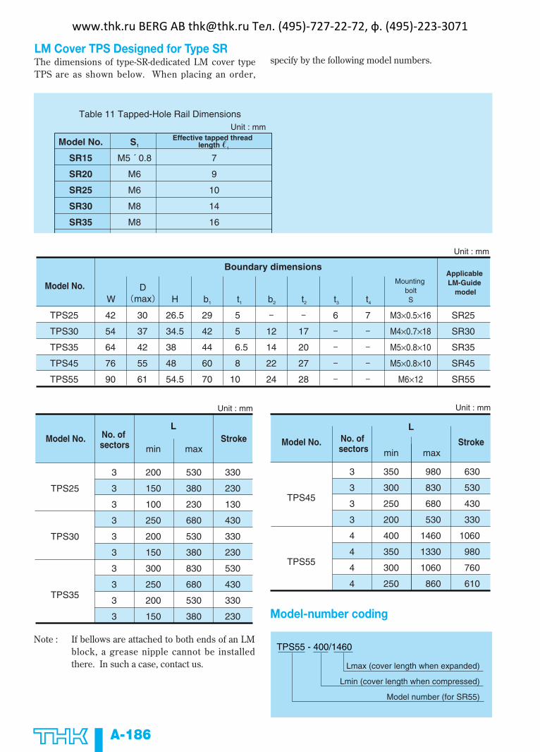
LM Cover TPS Designed for Type SRThe dimensions of type-SR-dedicated LM cover typeTPS are as shown below. When placing an order,
specify by the following model numbers.
A-186
7
9
10
14
16
Model No.
SR15
SR20
SR25
SR30
SR35
S1
M5 ´ 0.8
M6
M6
M8
M8
Unit : mm
Table 11 Tapped-Hole Rail Dimensions
Effective tapped thread length �1
Unit : mm
12
14
22
24
TPS25
TPS30
TPS35
TPS45
TPS55
42
54
64
76
90
30
37
42
55
61
26.5
34.5
38
48
54.5
29
42
44
60
70
5
5
6.5
8
10
17
20
27
28
6 7 M3×0.5×16
M4×0.7×18
M5×0.8×10
M5×0.8×10
M6×12
SR25
SR30
SR35
SR45
SR55
WD
max H b1 t1 b2 t2 t3 t4
Model No.
Boundary dimensionsMounting
boltS
Applicable LM-Guide
model
Unit : mm
3
3
3
3
3
3
3
3
3
3
200
150
100
250
200
150
300
250
200
150
530
380
230
680
530
380
830
680
530
380
330
230
130
430
330
230
530
430
330
230
TPS25
TPS30
TPS35
min
L
maxModel No. No. of
sectorsStroke
Unit : mm
TPS45
TPS55
3
3
3
3
4
4
4
4
350
300
250
200
400
350
300
250
980
830
680
530
1460
1330
1060
860
630
530
430
330
1060
980
760
610
min
L
maxModel No. StrokeNo. of
sectors
Note : If bellows are attached to both ends of an LMblock, a grease nipple cannot be installedthere. In such a case, contact us.
TPS55 - 400/1460
Lmax (cover length when expanded)
Lmin (cover length when compressed)
Model number (for SR55)
Model-number coding
www.thk.ru BERG AB [email protected] Тел. (495)-727-22-72, ф. (495)-223-3071
A-187
A-IV
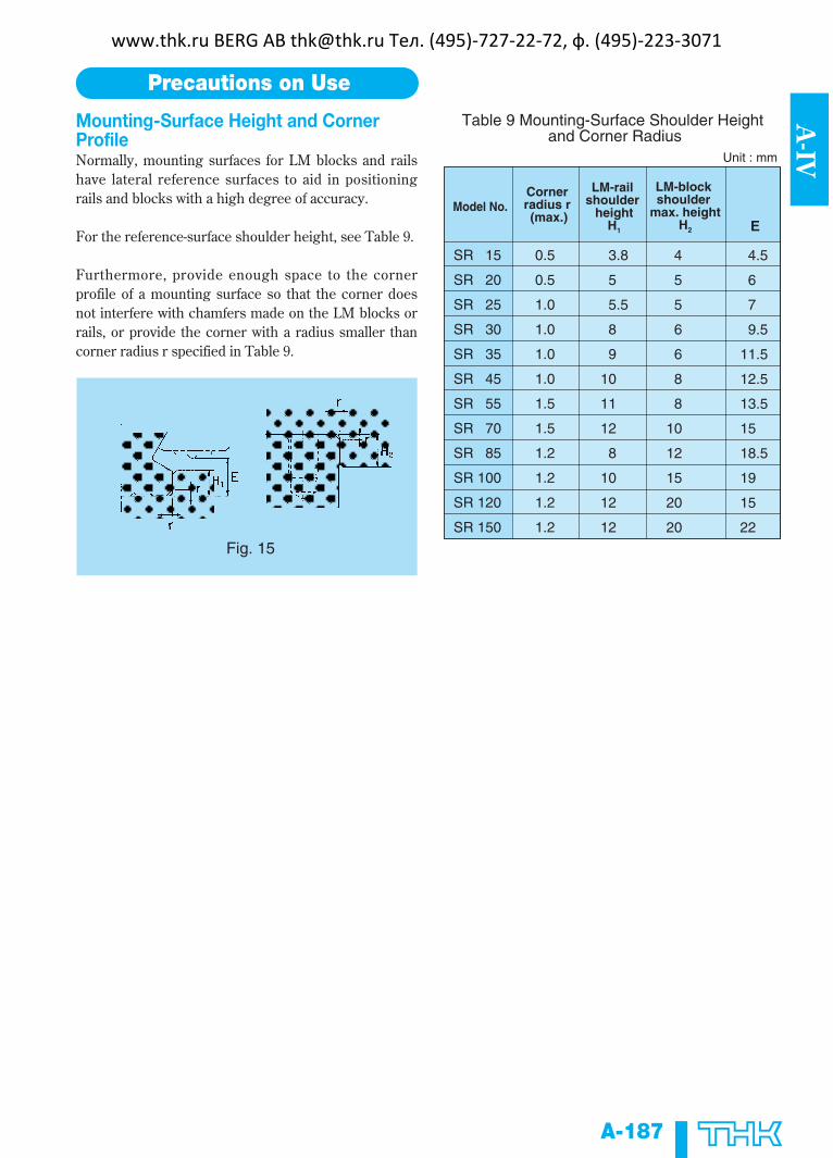
Mounting-Surface Height and CornerProfileNormally, mounting surfaces for LM blocks and railshave lateral reference surfaces to aid in positioningrails and blocks with a high degree of accuracy.
For the reference-surface shoulder height, see Table 9.
Furthermore, provide enough space to the cornerprofile of a mounting surface so that the corner doesnot interfere with chamfers made on the LM blocks orrails, or provide the corner with a radius smaller thancorner radius r specified in Table 9.
Precautions on Use
SR 15
SR 20
SR 25
SR 30
SR 35
SR 45
SR 55
SR 70
SR 85
SR 100
SR 120
SR 150
E
0.5
0.5
1.0
1.0
1.0
1.0
1.5
1.5
1.2
1.2
1.2
1.2
3.8
5
5.5
8
9
10
11
12
8
10
12
12
4
5
5
6
6
8
8
10
12
15
20
20
4.5
6
7
9.5
11.5
12.5
13.5
15
18.5
19
15
22
Unit : mm
Table 9 Mounting-Surface Shoulder Height and Corner Radius
Model No.Corner radius r (max.)
LM-rail shoulder
heightH1
LM-block shoulder
max. heightH2
Fig. 15
www.thk.ru BERG AB [email protected] Тел. (495)-727-22-72, ф. (495)-223-3071
A-188
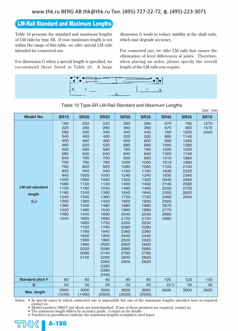
LM-Rail Standard and Maximum Lengths
Table 10 presents the standard and maximum lengthsof LM rails for type SR. If your maximum length is notwithin the range of this table, we offer special LM railsintended for connected use.
For dimension G when a special length is specified, werecommend those listed in Table 10. A large
dimension G tends to reduce stability at the shaft ends,which may degrade accuracy.
For connected use, we offer LM rails that ensure theelimination of level differences at joints. Therefore,when placing an order, please specify the overalllength of the LM rails you require.
Standard pitch F
G
Max. length
LM-rail standard
length
(L0)
SR15 SR20 SR25 SR30 SR35 SR45 SR55 SR70
160220280340400460520580640700760820940
1000106011201180124013001360142014801540
220280340400460520580640700760820940
10001060112011801240130013601420148015401600166017201780184019001960202020802140
220280340400460520580640700760820940
100010601120124013001360142014801540160016601720178018401900196020202080214022002260232023802440
280360440520600680760840920
100010801160124013201400148016401720180018801960204021202200228023602440252026002680276028402920
280360440520600680760840920
100010801160124013201400148016401720180018801960204021202200228023602440252026002680276028402920
570675780885990
109512001305141015151725183019352040214522502355246025652670277528802985
780900
1020114012601380150017401860198021002220234024602580270028202940
127015702020
Unit : mm
6020
2500(1240)
6020
3000(1480)
6020
3000(2020)
8020
3000(2520)
8020
3000(2520)
12030
3000
15035
3000
105 22.53000
Model No.
Table 10 Type-SR LM-Rail Standard and Maximum Lengths
Notes: • In special cases in which connected use is impossible but one of the maximum lengths specified here is required,contact us.
• Model numbers SR85T and above are semi-standard. If any of these products are required, contact us.• The maximum length differs by accuracy grade. Contact us for details• Numbers in parentheses indicate the maximum lengths of stainless steel types.
www.thk.ru BERG AB [email protected] Тел. (495)-727-22-72, ф. (495)-223-3071
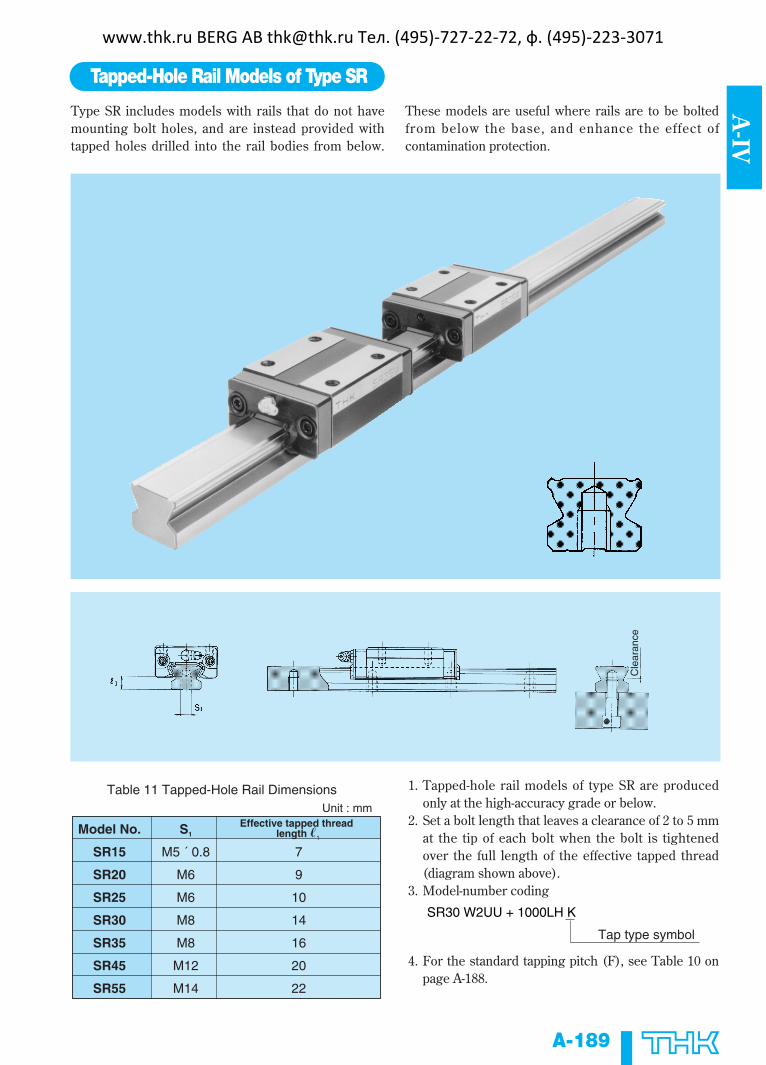
Type SR includes models with rails that do not havemounting bolt holes, and are instead provided withtapped holes drilled into the rail bodies from below.
These models are useful where rails are to be boltedfrom below the base, and enhance the effect ofcontamination protection.
A-189
A-IV
Tapped-Hole Rail Models of Type SR
1. Tapped-hole rail models of type SR are producedonly at the high-accuracy grade or below.
2. Set a bolt length that leaves a clearance of 2 to 5 mmat the tip of each bolt when the bolt is tightenedover the full length of the effective tapped thread(diagram shown above).
3. Model-number coding
4. For the standard tapping pitch (F), see Table 10 onpage A-188.
7
9
10
14
16
20
22
Model No.
SR15
SR20
SR25
SR30
SR35
SR45
SR55
S1
M5 ´ 0.8
M6
M6
M8
M8
M12
M14
Unit : mm
Table 11 Tapped-Hole Rail Dimensions
Effective tapped thread length �1
SR30 W2UU + 1000LH K
Tap type symbol
Cle
aran
ce
www.thk.ru BERG AB [email protected] Тел. (495)-727-22-72, ф. (495)-223-3071
A-190
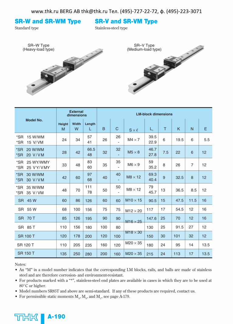
SR-W and SR-WM Type SR-V and SR-VM TypeStandard type Stainless-steel type
SR–W Type(Heavy-load type)
SR–V Type(Medium-load type)
*SR 15 W/WM*SR 15 V/ VM
*SR 20 W/WM*SR 20 V / VM
*SR 25 WY/WMY*SR 25 V Y/ VMY
*SR 30 W/WM*SR 30 V / VM
*SR 35 W/WM*SR 35 V / VM
SR 45 W
SR 55 W
SR 70 T
SR 85 T
SR 100 T
SR 120 T
SR 150 T
24
28
33
42
48
60
68
85
110
120
110
135
34
42
48
60
70
86
100
126
156
178
205
250
5741
66.548
8360
9768
11178
126
156
195
180
200
235
280
26
32
35
40
50
60
75
90
100
120
160
200
26-
32-
35-
40-
50-
60
75
90
80
100
120
160
M4 × 7
M5 × 8
M6 × 9
M8 × 12
M8 × 12
M10 × 15
M12 × 20
M16 × 25
M18 × 30
M20 × 35
M20 × 35
39.522.9
46.727.8
5935.2
69.340.4
7945.7
90.5
117
147.6
130
150
180
215
6
7.5
8
9
13
15
17
25
25
30
24
24
19.5
22
26
32.5
36.5
47.5
54.5
70
91.5
101
95
113
6
6
7
8
8.5
11.5
12
12
27
32
14
17
5.5
12
12
12
12
16
16
16
12
12
13.5
13.5
B C S × � L1 T K N E
Model No.Height
MWidth
WLength
L
External dimensions LM-block dimensions
Notes:• An “M” in a model number indicates that the corresponding LM blocks, rails, and balls are made of stainless
steel and are therefore corrosion- and environment-resistant.• For products marked with a “*”, stainless-steel end plates are available in cases in which they are to be used at
80°C or higher.• Model numbers SR85T and above are semi-standard. If any of these products are required, contact us.• For permissible static moments M
A, M
B, and M
C, see page A-179.
www.thk.ru BERG AB [email protected] Тел. (495)-727-22-72, ф. (495)-223-3071

A-191
A-IV
9.5
11
12.5
16
18
20.5
26
28
35.5
39
45.5
53
9.515.39
12.57.16
20.311.7
3017.2
41.723.8
55.3
89.1
156
120
148
279
411
19.311.1
25.214.4
39.522.5
56.832.5
77.244.1
101
157
266
224
283
377
537
0.20.12
0.30.2
0.40.3
0.80.5
1.20.8
2.2
3.6
7.0
10.1
14.1
-
-
60
60
60
80
80
105
120
150
180
210
230
250
1.2
2.1
2.7
4.3
6.4
11.3
12.8
22.8
34.9
46.4
-
-
3.5 × 6 × 4.5
6 × 9.5 × 8.5
7 × 11 × 9
7 × 11 × 9
9 × 14 × 12
11 × 17.5 × 14
14 × 20 × 17
18 × 26 × 22
18 × 26 × 22
22 × 32 × 25
26 × 39 × 30
33 × 48 × 36
15
20
23
28
34
45
48
70
85
100
114
144
12.5
15.5
18
23
27.5
35.5
38
47
65.5
70.3
65
77
W1
±0.05 W2 d1 × d2 × hCkN
C0
kN
PB1021B
B-M6F
B-M6F
B-M6F
B-M6F
B-PT1/8
B-PT1/8
B-PT1/8
A-PT1/8
A-PT1/8
B-PT1/4
B-PT1/4
Unit : mm
Grease nipple Width Height
M1
Pitch
FLM block
kg
LM rail
kg/m
LM-rail dimensions Basic load rating Mass
SR–W Type(Heavy-load type)
SR–V Type(Medium-load type)
• For standard LM-rail lengths, see page A-188.• For model-number coding, see page A-180.• SR85T and SR100T are provided with a grease nipple on the sides of their LM blocks.
(E)
www.thk.ru BERG AB [email protected] Тел. (495)-727-22-72, ф. (495)-223-3071

A-192
SR-TB and SR-TBM Type SR-SB and SR-SBM TypeStandard type Stainless-steel type
SR–TB Type(Heavy-load type)
SR–SB Type(Medium-load type)
*SR 15 TB/TBM*SR 15 SB/SBM
*SR 20 TB/TBM*SR 20 SB/SBM
*SR 25 TBY/TBMY*SR 25 SBY/SBMY
*SR 30 TB/TBM*SR 30 SB/SBM
*SR 35 TB/TBM*SR 35 SB/SBM
SR 45 TB
SR 55 TB
24
28
33
42
48
60
68
52
59
73
90
100
120
140
5741
66.548
8360
9768
11178
126
156
41
49
60
72
82
100
116
26-
32-
35-
40-
50-
60
75
4.5
5.5
7
9
9
11
14
39.522.9
46.727.8
5935.2
69.340.4
7945.7
90.5
117
7
9
10
10
13
15
17
19.5
22
26
32.5
36.5
47.5
54.5
6
6
7
8
8.5
11.5
12
5.5
12
12
12
12
16
16
B C S L1 T K N E
LM-block dimensions
Model No.Height
MWidth
WLength
L
External dimensions
Notes:• An “M” in a model number indicates that the corresponding LM blocks, rails, and balls are made of stainless
steel and are therefore corrosion- and environment-resistant.• For products marked with a “*”, stainless-steel end plates are available in cases in which they are to be used at
80°C or higher.• For permissible static moments M
A, M
B, and M
C, see page A-179.
www.thk.ru BERG AB [email protected] Тел. (495)-727-22-72, ф. (495)-223-3071

A-193
A-IV
PB1021B
B−M6F
B−M6F
B-M6F
B-M6F
B-PT1/8
B-PT1/8
18.5
19.5
25
31
33
37.5
46
9.51 5.39
12.5 7.16
20.311.7
3017.2
41.723.8
55.3
89.1
19.311.1
25.214.4
39.522.5
56.832.5
77.244.1
101
157
0.2 0.15
0.40.3
0.60.4
1.10.8
1.51.0
2.5
4.2
60
60
60
80
80
105
120
1.2
2.1
2.7
4.3
6.4
11.3
12.8
3.5 × 6 × 4.5
6 × 9.5 × 8.5
7 × 11 × 9
7 × 11 × 9
9 × 14 × 12
11 × 17.5 × 14
14 × 20 × 17
15
20
23
28
34
45
48
12.5
15.5
18
23
27.5
35.5
38
W1
±0.05 W2
HeightM1
PitchF d1 × d2 × h
CkN
C0
kN
Unit : mm
Grease nipple Width
LM block
kg
LM rail
kg/m
LM-rail dimensions Basic load rating Mass
SR–TB Type(Heavy-load type)
SR–SB Type(Medium-load type)
• For standard LM-rail lengths, see page A-188.• For model-number coding, see page A-180.
(E)
through through
www.thk.ru BERG AB [email protected] Тел. (495)-727-22-72, ф. (495)-223-3071