LIT1566 DV-HSW-21A DV-MFSW-21A COMBINED … not install near any heat sources such as radiators,...
21
DV-HSW-21A HDMI 2x1 Switcher Based on firmware 02.00 DV-MFSW-21A HDMI / VGA 2x1 Switcher Based on firmware 01.09 43098 LIT1566 User Manual
-
Upload
nguyenmien -
Category
Documents
-
view
216 -
download
1
Transcript of LIT1566 DV-HSW-21A DV-MFSW-21A COMBINED … not install near any heat sources such as radiators,...

DV-HSW-21A HDMI 2x1 Switcher
Based on firmware 02.00
DV-MFSW-21A HDMI / VGA 2x1 Switcher
Based on firmware 01.09
43098 LIT1566
User Manual

2
IMPORTANT SAFETY INSTRUCTIONS Contents are subject to change without notice
Warnings
To reduce the risk of fire, electric shock or product damage:
1. Do not expose this device to
rain, moisture, dripping or
splashing and that no objects
filled with liquids, such as vases,
shall be placed on the unit.
6. Clean this device only
with dry cloth.
2. Do not install or place this unit
in a bookcase, built-in cabinet or
in another confined space.
Ensure the unit is well ventilated.
3. To prevent risk of electric shock or fire hazard due to overheating, do not obstruct the unit’s ventilation openings with newspapers, tablecloths, curtains, and similar items.
4. Do not install near any heat
sources such as radiators, heat
registers, stoves, or other device
(including amplifiers) that
produce heat.
5. Do not place sources of open
flames, such as lighted candles,
on the unit.
7. Unplug this device
during lightning storms or
when unused for long
periods of time.
8. Protect cables and
cords from being walked
on or pinched particularly
at plugs.
9. Only use
attachments/accessories
specified by FSR.
10. Refer all servicing to
qualified service
personnel.

3
Table of Contents
Important Safety Instructions ....................................................................... 2
Overview ......................................................................................................... 4
Features .......................................................................................................... 4
Package Contents .......................................................................................... 6
Typical Application ........................................................................................ 6
Front Panel ............................................................................................... 7
Rear Panel ................................................................................................ 8
Hardware Installation................................................................................... 10
EDID Management ....................................................................................... 11
RS-232 Operation ......................................................................................... 12
RS-232 Serial Protocol ........................................................................... 12
Request/Response Format .............................................................. 12
Field Separators .............................................................................. 12
Command Request Syntax: ............................................................. 13
Acknowledging Receipt of Commands ............................................ 14
Error Response ............................................................................... 14
REQUEST LIST QUICK REFERENCE ........................................... 14
Connection Request ........................................................................ 15
Disconnect Request ........................................................................ 16
HDCP Request ................................................................................ 16
Model Request ................................................................................ 17
Reconnect Request ......................................................................... 18
Status Request ................................................................................ 18
Version Request .............................................................................. 19
Specifications .............................................................................................. 20
Limited Warranty .......................................................................................... 21

4
OVERVIEW The DV-HSW-21A is a 2x1 HDMI switcher supporting up to 4K x 2K @ 30Hz.
The DV-MFSW-21A is a unique switcher and a must have for installations
spanning new and legacy technology. This switcher has 1 HDMI input
supporting resolutions up to 4K x 2K @ 30Hz and 1 VGA (HD-15) input
supporting resolutions up to 1920 x 1200 @ 60Hz. The HD-15 input is paired
with a stereo audio input on a 3.5mm mini stereo connector. When selected,
the analog video is converted to HDMI and the audio is embedded greatly
simplifying connections and operations downstream. Both of the 2x1 switcher
models feature 4-way control via simple front panel push buttons, screw
terminal contact closures with LED feed-back, RS- 232 serial control, and auto
sense switching technology. In auto sense mode, the switcher will switch when
the current video source being displayed is turned off either via keyboard
function buttons or from signal loss. These options help in making these a
perfect solution for any system.
FEATURES DV-HSW-21A:
• 2x1 HDMI Switcher Supporting up to 4K x 2K @ 30 Hz
• HDMI 1.4 and HDCP Compliant
• Embedded Audio Support
DV-MFSW-21A:
• 2x1 Switcher with 1 HDMI and 1 VGA (HD-15) Input and HDMI Output
• HDMI Supports Resolutions up to 4K x 2K @ 30Hz
• VGA (HD-15) Supports Resolutions up to 1920 x 1200 @ 60Hz
• Analog Video converted to HDMI with Audio Embedded
BOTH MODELS:
• HDMI 1.4 and HDCP Compliant
•Control Functions (Both Models)
• Auto sense Automatic Switching Technology

5
• Front Panel Push Button Local Control
• Contact Closure Control with +12 volt Lamp/LED output (@100 mA when
active)
• Serial (RS-232) Remote Control

6
PACKAGE CONTENTS
1 x DV-MFSW-21A or DV-HSW-21A Switcher.
1 x 12VDC Power Supply
2 x Surface Mount Brackets
1 x 3.81mm Phoenix Connector (3 Pin)
1 x 3.81mm Phoenix Connector (5 Pin)
TYPICAL APPLICATION DV-MFSW-21A model shown. DV-HSW-21A has two HDMI (no VGA) input
connectors and no audio input connector
DVD
HDMIVGA Audio
TV
HDMIHDMI connector on
DV-HSW- 21A model
(DV-MFSW-21 ONLY)

7
FRONT PANEL
DV-HSW4K-21A / DV-MFSW-21A
ID Name Description
1 Power LED Lit when power is on
2 Select Button Press to select HDMI IN as input source
3 Indicator Lit when Source is selected
4 Select Button
Press to select VGA or HDMI on
DV-HSW-21A as input source
5 Indicator Lit when VGA is selected
1 2 3 4 5

8
REAR PANEL
DV-MFSW-21A model shown. DV-HSW-21A has two HDMI (no VGA) input
connectors and no audio input connector
ID Name Description
1 Power 12VDC power input
2 RS232 RS232 control.
For the API commands, please refer to
DV-MFSW-21A or DV-HSW-21A RS-232
Serial Protocol
3 CONTACT
CLOSURE
Connects to a control device such as keypad
for switching between HDMI IN 1 and PC IN 2.
Pin SW-1 and GND are used for selecting
HDMI IN as the input source. If the input
source is HDMI IN, the LED-1 indicator on the
keypad will be on.
Pin SW-2 and GND are used for selecting
VGA as the input source. If the input source is
VGA, the LED-2 indicator on the keypad will
be on.
1 2 3 4 5 6 7 8
9
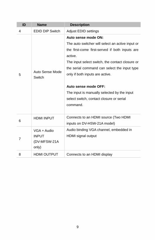
ID Name Description
4 EDID DIP Switch Adjust EDID settings
5 Auto Sense Mode
Switch
Auto sense mode ON:
The auto switcher will select an active input or
the first-come first-served if both inputs are
active.
The input select switch, the contact closure or
the serial command can select the input type
only if both inputs are active.
Auto sense mode OFF:
The input is manually selected by the input
select switch, contact closure or serial
command.
6 HDMI INPUT Connects to an HDMI source (Two HDMI
inputs on DV-HSW-21A model)
7
VGA + Audio
INPUT
(DV-MFSW-21A
only)
Audio binding VGA channel, embedded in
HDMI signal output
8 HDMI OUTPUT Connects to an HDMI display

10
HARDWARE INSTALLATION DV-MFSW-21A model shown. DV-HSW-21A has two HDMI (no VGA) input
connectors and no audio input connector
1. Connect the HDMI or VGA input source (such as DVD Player, Apple TV,
and STB) to the unit.
2. Connect the HDMI display device (such as HD-LCD) to the HDMI output
port of the switcher.
3. Connect the power supply to the HDMI switcher and power on all the
devices.
4. To operate the unit, use the front panel select button, remote or contact
closure
Note: The contact closure can be used with control device such as a keypad.
DVD
HDMIVGA Audio
TV
HDMI

11
EDID MANAGEMENT
Note: The change doesn’t take effect until you restart the Switcher.
DV-MFSW-21A EDID for VGA only, HDMI pass through.
Position Functions
0 1280x800 60Hz
1 1920x1200 60Hz
2 1920x1080 60Hz (default)
3 1280x720 60Hz
4 1024x768 60Hz
5 800x600 60Hz
6 Reserved
7 Reserved
DV-HSW-21A EDID for both inputs.
Position Functions
0 Automatically copy HDMI display's EDID to all HDMI Inputs, if
failed, the EDID of all HDMI inputs won’t change.
1 4K2K 30Hz 2CH (default)
2 1280 x 800 60Hz 2CH
3 1920 x 1080 60Hz 2CH
4 1920 x 1200 60Hz 2CH
5 1280 x 720 60Hz 2CH
6 1024 x768 60Hz 2CH
7 800x600 60Hz 2CH

12
RS-232 OPERATION The switchers may be configured or queried via the RS232 serial
connection.
Baud Rate: 38,400bps
Data bits: 8
Stop bits: 1
Parity: None
Flow control: None
Computer (DTE) DV-HSW-21A / DV-MFSW-21A Pin 2 Rx Tx Pin 3 Tx Rx
Pin 5 Ground — Ground
RS-232 SERIAL PROTOCOL
The DV‐MFSW‐21A and the DV‐HSW‐21A switcher may be configured or
queried via the RS‐232 serial connection.
Request/Response Format All requests and responses will be entirely in ASCII. The requests can be in
either upper or lower case.
All requests will have three character command field followed by the data required
for that specific request. All requests are terminated with a carriage return (0Dh), which
will be referred to in this document as <cr>. All responses are terminated with a carriage
return <cr> and a line feed (0Ah) which will be referred as <lf>.
Field Separators Fields are separated by white space, that is any number of spaces or tabs as long
13
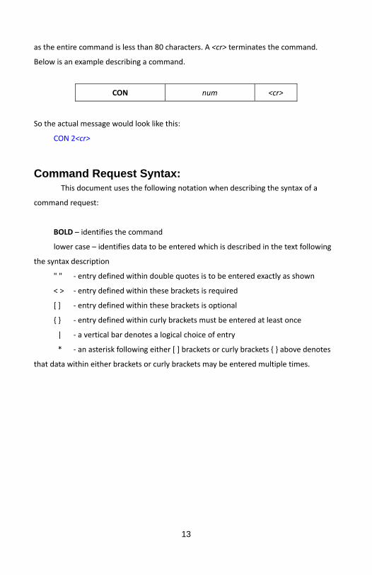
as the entire command is less than 80 characters. A <cr> terminates the command.
Below is an example describing a command.
CON num <cr>
So the actual message would look like this:
CON 2<cr>
Command Request Syntax: This document uses the following notation when describing the syntax of a
command request:
BOLD – identifies the command
lower case – identifies data to be entered which is described in the text following
the syntax description
" " ‐ entry defined within double quotes is to be entered exactly as shown
< > ‐ entry defined within these brackets is required
[ ] ‐ entry defined within these brackets is optional
{ } ‐ entry defined within curly brackets must be entered at least once
| ‐ a vertical bar denotes a logical choice of entry
* ‐ an asterisk following either [ ] brackets or curly brackets { } above denotes
that data within either brackets or curly brackets may be entered multiple times.

14
Acknowledging Receipt of Commands Each request sent to the switcher will have by default two possible responses, an
acknowledgement of a correct request or an error response. The acknowledge response
will be:
Ok<cr><lf>
Error Response It is inevitable that errors occur in the requests sent to the switcher. If an
invalid command is sent to the switcher, the switcher will respond with the message
"ERR: unknown command". If an invalid parameter is sent to the switcher, the
switcher will respond with the message "ERR:" followed by the valid syntax for the
errored entry.
Example:
A connect request with an incorrect input number:
CON 3<cr>
The error response would be:
ERR: CON 3<cr>
REQUEST LIST QUICK REFERENCE
REQUEST DESCRIPTION
CON Connection Request
DIS Disconnect Request
HDCP High Definition Contention Protection Status Request
MOD Model Request
REC Reconnect Request
STA Status Request
VER Request Version Number

15
Connection Request The connection request is used to connect one of the two available inputs to the
output.
A connection may be disconnected by using the DIS command (see later in document).
CON input | "?" <cr>
Syntax: CON <input | "?"><cr>
Where:
CON Connection request header
input Input number in the range 1‐2
"?" Request to return the currently selected input (the front
panel LEDs reflect the currently selected input).
(Note: A CON input command will override the disconnected output, ie via the DIS
command. See below for description of DIS command.)
Examples:
To connect input 2 to output, the connection request would look like this:
CON 2<cr>
To request the currently connected input, the connection request would look
like this:
CON ?<cr>
The response from the switcher would be:
CON 2<cr><lf>
If a previously connected input were subsequently disconnected via the DIS
command, then the CON ? command will return the currently selected input.
16
Disconnect Request
The disconnect request is used to disconnect (disable) the output of the
switcher.
DIS <cr>
Syntax: DIS<cr>
Where:
DIS Disconnect request header
Example:
To disconnect (disable) the output of the switcher, the user would send the
following message:
DIS<cr>
HDCP Request The High‐bandwidth Digital Content Protection status request allows identification
of the presence of HDCP on the input(s). The format for the HDCP request is as follows:
HDCP <cr>
Syntax: HDCP<cr>
Where:
HDCP High Definition Content Protection request header
Response from DV‐MFSW‐21A: HDCP x
Response from DV‐HSW‐21A: HDCP xx
Where:
x is either 0 or 1, with 0 representing that HDCP is not present and 1 representing
that HDCP is present.

17
Example:
To query the HDCP status of the unit the user would send the following message:
HDCP<cr>
The response for the DV‐MFSW‐21A switcher could be:
HDCP 1<cr><lf>
That is, HDCP is present on input 1.
The response for the DV‐HSW‐21A switcher could be:
HDCP 01<cr><lf>
That is, HDCP is not present on input 1 and HDCP is present on input 2.
Model Request The MOD Model request allows identification of the model number of the switcher.
The unit will return the current model identification, ie DV‐MFSW‐21A. The format for
the model request is as follows:
MOD <cr>
Syntax: MOD<cr>
Where:
MOD Model request header
Example:
To query the model number of the unit the user would send the following
message:
MOD<cr>
The response for the DV‐MFSW‐21A switcher would be:
MOD DV‐MFSW‐21A<cr><lf>
18
Reconnect Request The REC request allows the user to reconnect the disconnected output to the
currently selected input. Note that the input to be reconnected is as indicated by the
input LED on the front panel. The command has no effect if an input is already
connected to the output.
REC <cr>
Syntax: REC<cr>
Where:
REC Reconnect request header
Example:
To reconnect the previously connected input 2 to output, the user would send the
following message:
REC<cr>
Status Request The STA request returns the presence of signal on the respective inputs, 1 =
signal present, 0 = no signal present.
STA <cr>
Syntax: STA<cr>
Where:
STA Status request header
Example:
To query for the presence of signal on inputs 1 and 2, the user would send the
following message:
STA<cr>
If signal were present on input 1 but not on input 2, the response from the switcher

19
would be:
STA 10<cr><lf>
If signal were not present on input 1 and present on input 2, the response from the
switcher would be:
STA 01<cr><lf>
Version Request In order to be able to identify the current firmware version populated in the
unit, the user may request using the VER request. The format for the request will be as
follows:
VER <cr>
Syntax: VER<cr>
Where:
VER Version Request header
Response form DV‐MFSW‐21A: VER DV‐MFSW‐21A <XX.xx>
Response form DV‐HSW‐21A: VER DV‐HSW‐21A <XX.xx>
Where:
XX.xx XX = Major version number, xx = Minor version number
Example:
VER<cr>
To which the DV‐MFSW‐21A switcher will respond:
VER DV‐MFSW‐21A 01.09<cr>

20
SPECIFICATIONS DV-HSW-21A / DV-MFSW-21A
Video Input 2 x HDMI Type A 19-pin, female( DV-HSW-21)
1 VGA and 1 HDMI (DV-MFSW-21 only)
Audio Input 3.5mm Stereo (DV-MFSW-21 only)
Video Output 1 x HDMI Type A 19-pin, female
RS-232 3 Pin Pluggable Screw Terminal
Contact Closure 5 Pin Pluggable Screw Terminal
AC Power External 12VDC Power Supply with Locking
Connector Operational
Power Input 110-240 VAC
Power Consumption 12VDC 0.25A
Dimensions 7 1/2" (190.2mm) W x 3 1/4" (82.7mm) D x 1"
(26.2mm) H
Weight Weight
1 lbs (0.45 kg)
Supported Formats HDMI: 3840x2160 @30Hz (4K x 2K @30Hz)
VGA: 1920 x 1200 @ 60Hz

21
LIMITED WARRANTY The DV-HSW-21A / DV-MFSW-21A Switchers are warranted against failures due to defective parts or faulty workmanship for a period of three years after delivery to the original owner. During this period, FSR will make any necessary repairs or replace the Unit without charge for parts or labor. Shipping charges to the factory or repair station must be prepaid by the owner, return-shipping charges (via UPS Ground) will be paid by FSR. This warranty applies only to the original owner and is not transferable. In addition, it does not apply to repairs done by other than the FSR factory or Authorized Repair Stations. This warranty shall be cancelable by FSR at its sole discretion if the Unit has been subjected to physical abuse or has been modified in any way without written authorization from FSR. FSR’s liability under this warranty is limited to repair or replacement of the defective unit. FSR will not be responsible for incidental or consequential damages resulting from the use or misuse of its products. Some states do not allow the exclusion of incidental or consequential damages, so the above limitations may not apply to you. This warranty gives you specific legal rights, and you may also have other rights which vary from state to state. Warranty claims should be accompanied by a copy of the original purchase invoice showing the purchase date (if a Warranty Registration Card was mailed in at the time of purchase, this is not necessary). Before returning any equipment for repair, please read the important information on service below. SERVICE Before returning any equipment for repair, please be sure that it is adequately packed and cushioned against damage in shipment, and that it is insured. We suggest that you save the original packaging and use it to ship the product for servicing. Also, please enclose a note giving your name, address, phone number and a description of the problem. NOTE: all equipment being returned for repair must have a Return authorization (RMA) Number. To get a RMA Number, please call the FSR Service Department (1-800-332-FSR1). Please display your RMA Number prominently on the front of all packages.
CONTACT INFORMATION:
FSR INC.
244 Bergen Blvd.
Woodland Park, NJ 07424
Phone: (973) 785-4347
Order Desk Fax: (973) 785-4207
Web Site: http://www.fsrinc.com