Liquid-Crystal-on-Silicon for Augmented Reality Displays
17
applied sciences Review Liquid-Crystal-on-Silicon for Augmented Reality Displays Yuge Huang 1 , Engle Liao 2 , Ran Chen 1,3 and Shin-Tson Wu 1, * 1 College of Optics and Photonics, University of Central Florida, Orlando, FL 32816, USA; [email protected] (Y.H.); [email protected] (R.C.) 2 Snail Innovation Institute, San Jose, CA 95112, USA; [email protected] 3 Key Laboratory of Applied Surface and Colloid Chemistry, School of Materials Science and Engineering, Shaanxi Normal University, Xi’an 710119, China * Correspondence: [email protected]; Tel.: +1-407-823-4763 Received: 30 October 2018; Accepted: 20 November 2018; Published: 23 November 2018 Abstract: In this paper, we review liquid-crystal-on-silicon (LCoS) technology and focus on its new application in emerging augmented reality (AR) displays. In the first part, the LCoS working principles of three commonly adopted LC modes—vertical alignment and twist nematic for amplitude modulation, and homogeneous alignment for phase modulation—are introduced and their pros and cons evaluated. In the second part, the fringing field effect is analyzed, and a novel pretilt angle patterning method for suppressing the effect is presented. Moreover, we illustrate how to integrate the LCoS panel in an AR display system. Both currently available intensity modulators and under-developing holographic displays are covered, with special emphases on achieving high image quality, such as a fast response time and high-resolution. The rapidly increasing application of LCoS in AR head-mounted displays and head-up displays is foreseeable. Keywords: liquid-crystal-on-silicon; fringing field effect; augmented reality displays; head-mounted displays; head-up displays 1. Introduction Dating from the 1970s, Hughes research labs creatively combined liquid crystal (LC) with semiconductor substrates, enabling optically addressed liquid crystal light valves [1,2], which paved the way for the invention of liquid-crystal-on-silicon (LCoS) display technology [3–5]. Through decades of extensive efforts, LCoS technology has proven its success in a wide range of fields like displays [6–13], adaptive optics [14,15], metrology [16,17], telecommunications [18], quantum physics [19,20], etc. The emergence of LCoS is jointly contributed by the application of liquid crystal (LC) electro-optic response behaviors and the development of the silicon complementary metal oxide semiconductor (CMOS) backplane technique. The structure of a typical reflective LCoS panel is shown in Figure 1: an LC layer is sandwiched between an indium tin oxide (ITO)-coated glass and a CMOS backplane. Two thin polyimide (PI) alignment layers determine the LC alignment direction. The Aluminum (Al) electrodes on the Silicon CMOS backplane are pixelated to provide independent voltage control. When an incident linearly polarized light traversing through the LC layer twice, its polarization state or phase is modulated depending on the LC alignment mode. Recently, LCoS has been widely implemented in augmented reality (AR) displays because of its high luminance (>30,000 nits), compactness, high-resolution density (>4000 pixels per inch), and potential of holography generation [12,21–23]. However, the cutting edge LCoS still needs improvement to meet the stringent AR requirements. In this paper, we review the LCoS technology intended for AR displays. In Section 2, we briefly describe the basic light modulation principles of Appl. Sci. 2018, 8, 2366; doi:10.3390/app8122366 www.mdpi.com/journal/applsci
Transcript of Liquid-Crystal-on-Silicon for Augmented Reality Displays
applied sciences
Review
Liquid-Crystal-on-Silicon for AugmentedReality Displays
Yuge Huang 1, Engle Liao 2 , Ran Chen 1,3 and Shin-Tson Wu 1,*1 College of Optics and Photonics, University of Central Florida, Orlando, FL 32816, USA;
[email protected] (Y.H.); [email protected] (R.C.)2 Snail Innovation Institute, San Jose, CA 95112, USA; [email protected] Key Laboratory of Applied Surface and Colloid Chemistry, School of Materials Science and Engineering,
Shaanxi Normal University, Xi’an 710119, China* Correspondence: [email protected]; Tel.: +1-407-823-4763
Received: 30 October 2018; Accepted: 20 November 2018; Published: 23 November 2018
Abstract: In this paper, we review liquid-crystal-on-silicon (LCoS) technology and focus on itsnew application in emerging augmented reality (AR) displays. In the first part, the LCoS workingprinciples of three commonly adopted LC modes—vertical alignment and twist nematic for amplitudemodulation, and homogeneous alignment for phase modulation—are introduced and their prosand cons evaluated. In the second part, the fringing field effect is analyzed, and a novel pretiltangle patterning method for suppressing the effect is presented. Moreover, we illustrate how tointegrate the LCoS panel in an AR display system. Both currently available intensity modulators andunder-developing holographic displays are covered, with special emphases on achieving high imagequality, such as a fast response time and high-resolution. The rapidly increasing application of LCoSin AR head-mounted displays and head-up displays is foreseeable.
Keywords: liquid-crystal-on-silicon; fringing field effect; augmented reality displays; head-mounteddisplays; head-up displays
1. Introduction
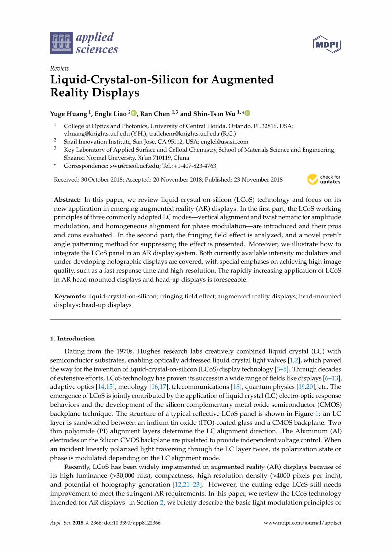
Dating from the 1970s, Hughes research labs creatively combined liquid crystal (LC) withsemiconductor substrates, enabling optically addressed liquid crystal light valves [1,2], which pavedthe way for the invention of liquid-crystal-on-silicon (LCoS) display technology [3–5]. Through decadesof extensive efforts, LCoS technology has proven its success in a wide range of fields like displays [6–13],adaptive optics [14,15], metrology [16,17], telecommunications [18], quantum physics [19,20], etc. Theemergence of LCoS is jointly contributed by the application of liquid crystal (LC) electro-optic responsebehaviors and the development of the silicon complementary metal oxide semiconductor (CMOS)backplane technique. The structure of a typical reflective LCoS panel is shown in Figure 1: an LClayer is sandwiched between an indium tin oxide (ITO)-coated glass and a CMOS backplane. Twothin polyimide (PI) alignment layers determine the LC alignment direction. The Aluminum (Al)electrodes on the Silicon CMOS backplane are pixelated to provide independent voltage control. Whenan incident linearly polarized light traversing through the LC layer twice, its polarization state orphase is modulated depending on the LC alignment mode.
Recently, LCoS has been widely implemented in augmented reality (AR) displays because ofits high luminance (>30,000 nits), compactness, high-resolution density (>4000 pixels per inch),and potential of holography generation [12,21–23]. However, the cutting edge LCoS still needsimprovement to meet the stringent AR requirements. In this paper, we review the LCoS technologyintended for AR displays. In Section 2, we briefly describe the basic light modulation principles of
Appl. Sci. 2018, 8, 2366; doi:10.3390/app8122366 www.mdpi.com/journal/applsci
Appl. Sci. 2018, 8, 2366 2 of 17
LCoS. In Section 3, we address the fringing field effect issue impairing the LCoS display performance,and propose a new device structure to mitigate this problem. High-resolution and small-pitch LCoSpanels are especially desirable for augmented reality displays, but how to suppress the fringing fieldeffect remains a technical challenge. In the last section, the LCoS-integrated AR head-mounted display(HMD) and head-up display (HUD) systems are demonstrated. The key parameters determining thedisplay performance are discussed in detail.
Appl. Sci. 2018, 8, x FOR PEER REVIEW 2 of 18
and propose a new device structure to mitigate this problem. High-resolution and small-pitch LCoS panels are especially desirable for augmented reality displays, but how to suppress the fringing field effect remains a technical challenge. In the last section, the LCoS-integrated AR head-mounted display (HMD) and head-up display (HUD) systems are demonstrated. The key parameters determining the display performance are discussed in detail.
Figure 1. The schematic of a LCoS structure.
2. LCoS Working Principles
2.1. Birefringence Effect of Liquid Crystals
Figure 2 illustrates the working mechanism of an LC phase retarder. Here, we assume the LC molecules are uniformly aligned along the x-axis with a tilt angle θ (Figure 2a). The uniaxial LC exhibits an extraordinary refractive index ne along its optical axis and an ordinary refractive index no along the two orthogonal axes. Thus, the corresponding birefringence is defined as Δn = ne − no. In Figure 2b, when an incident light passes through the LC layer along the z-axis, the x-polarized light experiences a tilt-angle-dependent refractive index nx (θ), while the y-polarized light experiences a constant index ny = no. The accumulated phase retardation between the two linear polarizations is
2[ ] .x yn n dπλ
Γ = − ⋅ ⋅ (1)
Here d is the cell gap (LC layer thickness), and nx (θ) follows
( )2 2
2 2 21 cos sin .
e oxn nn
θ θθ
= + (2)
In a reflective display, the incident light passes through the LC layer twice. As a result, the effective cell gap is 2d and Γ is doubled.
(a) (b)
Figure 2. (a) The schematic structure of an LCoS phase retarder. (b) Refractive index ellipse of a uniaxial liquid crystal.
When an external voltage is applied, the LC molecules (with Δε > 0) would reorient toward the electric field direction which, in turn, modifies the phase and polarization of the outgoing light.
Figure 1. The schematic of an LCoS structure.
2. LCoS Working Principles
2.1. Birefringence Effect of Liquid Crystals
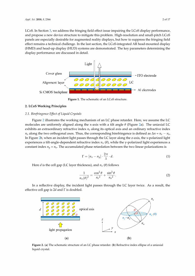
Figure 2 illustrates the working mechanism of an LC phase retarder. Here, we assume the LCmolecules are uniformly aligned along the x-axis with a tilt angle θ (Figure 2a). The uniaxial LCexhibits an extraordinary refractive index ne along its optical axis and an ordinary refractive indexno along the two orthogonal axes. Thus, the corresponding birefringence is defined as ∆n = ne − no.In Figure 2b, when an incident light passes through the LC layer along the z-axis, the x-polarized lightexperiences a tilt-angle-dependent refractive index nx (θ), while the y-polarized light experiences aconstant index ny = no. The accumulated phase retardation between the two linear polarizations is
Γ = [nx − ny] ·2π
λ· d. (1)
Here d is the cell gap (LC layer thickness), and nx (θ) follows
1
nx(θ)2 =
cos2 θ
ne2 +sin2 θ
no2 . (2)
In a reflective display, the incident light passes through the LC layer twice. As a result, theeffective cell gap is 2d and Γ is doubled.
Appl. Sci. 2018, 8, x FOR PEER REVIEW 2 of 18
and propose a new device structure to mitigate this problem. High-resolution and small-pitch LCoS panels are especially desirable for augmented reality displays, but how to suppress the fringing field effect remains a technical challenge. In the last section, the LCoS-integrated AR head-mounted display (HMD) and head-up display (HUD) systems are demonstrated. The key parameters determining the display performance are discussed in detail.
Figure 1. The schematic of a LCoS structure.
2. LCoS Working Principles
2.1. Birefringence Effect of Liquid Crystals
Figure 2 illustrates the working mechanism of an LC phase retarder. Here, we assume the LC molecules are uniformly aligned along the x-axis with a tilt angle θ (Figure 2a). The uniaxial LC exhibits an extraordinary refractive index ne along its optical axis and an ordinary refractive index no along the two orthogonal axes. Thus, the corresponding birefringence is defined as Δn = ne − no. In Figure 2b, when an incident light passes through the LC layer along the z-axis, the x-polarized light experiences a tilt-angle-dependent refractive index nx (θ), while the y-polarized light experiences a constant index ny = no. The accumulated phase retardation between the two linear polarizations is
2[ ] .x yn n dπλ
Γ = − ⋅ ⋅ (1)
Here d is the cell gap (LC layer thickness), and nx (θ) follows
( )2 2
2 2 21 cos sin .
e oxn nn
θ θθ
= + (2)
In a reflective display, the incident light passes through the LC layer twice. As a result, the effective cell gap is 2d and Γ is doubled.
(a) (b)
Figure 2. (a) The schematic structure of an LCoS phase retarder. (b) Refractive index ellipse of a uniaxial liquid crystal.
When an external voltage is applied, the LC molecules (with Δε > 0) would reorient toward the electric field direction which, in turn, modifies the phase and polarization of the outgoing light.
Figure 2. (a) The schematic structure of an LC phase retarder. (b) Refractive index ellipse of a uniaxialliquid crystal.
Appl. Sci. 2018, 8, 2366 3 of 17
When an external voltage is applied, the LC molecules (with ∆ε > 0) would reorient towardthe electric field direction which, in turn, modifies the phase and polarization of the outgoinglight. Depending on the surface alignment and the LC material properties, three LC modes arewidely adopted: vertical alignment (VA) and mixed-mode twist nematic (MTN) mainly for intensitymodulation, as well as the homogeneous alignment for phase modulation.
2.2. Vertical Alignment Mode
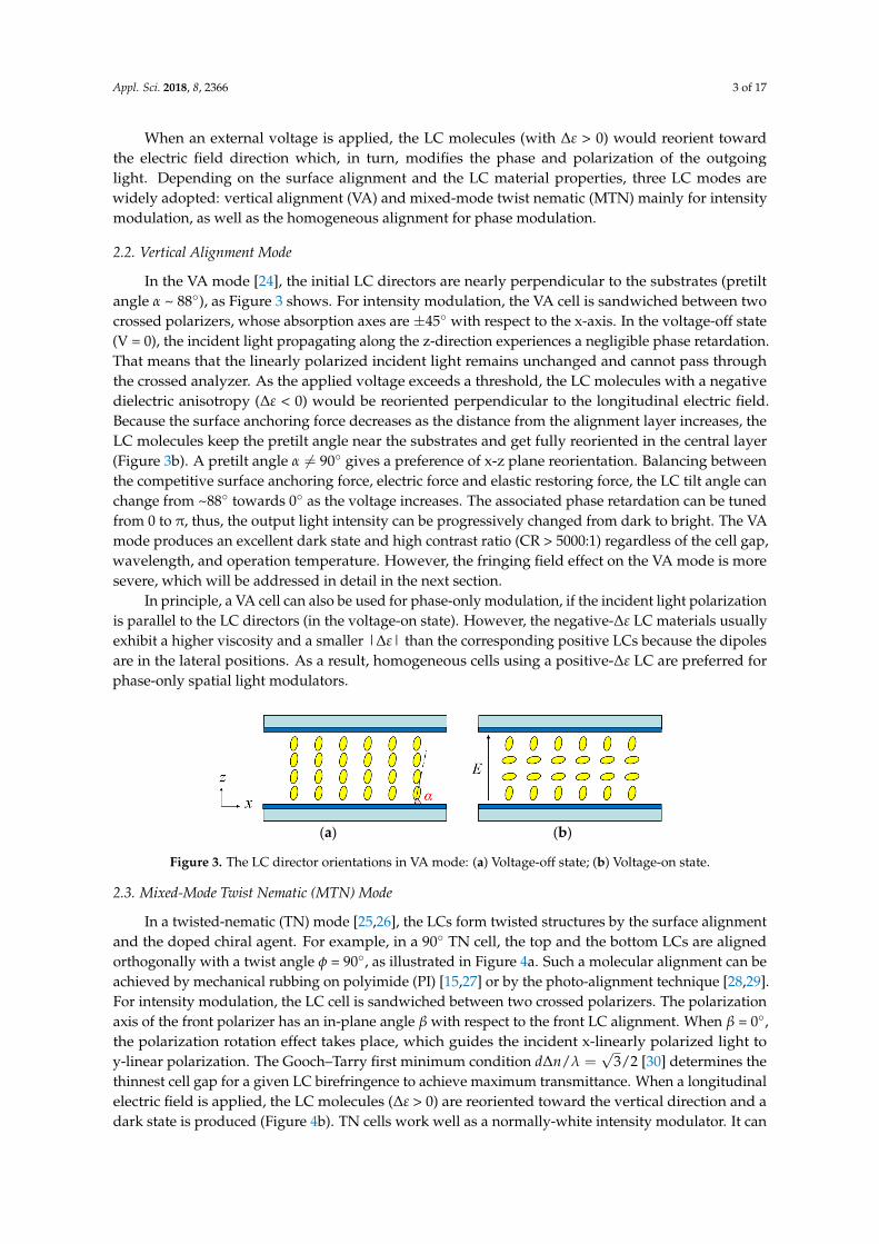
In the VA mode [24], the initial LC directors are nearly perpendicular to the substrates (pretiltangle α ~ 88), as Figure 3 shows. For intensity modulation, the VA cell is sandwiched between twocrossed polarizers, whose absorption axes are ±45 with respect to the x-axis. In the voltage-off state(V = 0), the incident light propagating along the z-direction experiences a negligible phase retardation.That means that the linearly polarized incident light remains unchanged and cannot pass throughthe crossed analyzer. As the applied voltage exceeds a threshold, the LC molecules with a negativedielectric anisotropy (∆ε < 0) would be reoriented perpendicular to the longitudinal electric field.Because the surface anchoring force decreases as the distance from the alignment layer increases, theLC molecules keep the pretilt angle near the substrates and get fully reoriented in the central layer(Figure 3b). A pretilt angle α 6= 90 gives a preference of x-z plane reorientation. Balancing betweenthe competitive surface anchoring force, electric force and elastic restoring force, the LC tilt angle canchange from ~88 towards 0 as the voltage increases. The associated phase retardation can be tunedfrom 0 to π, thus, the output light intensity can be progressively changed from dark to bright. The VAmode produces an excellent dark state and high contrast ratio (CR > 5000:1) regardless of the cell gap,wavelength, and operation temperature. However, the fringing field effect on the VA mode is moresevere, which will be addressed in detail in the next section.
In principle, a VA cell can also be used for phase-only modulation, if the incident light polarizationis parallel to the LC directors (in the voltage-on state). However, the negative-∆ε LC materials usuallyexhibit a higher viscosity and a smaller |∆ε| than the corresponding positive LCs because the dipolesare in the lateral positions. As a result, homogeneous cells using a positive-∆ε LC are preferred forphase-only spatial light modulators.
Appl. Sci. 2018, 8, x FOR PEER REVIEW 3 of 18
Depending on the surface alignment and the LC material properties, three LC modes are widely adopted: vertical alignment (VA) and mixed-mode twist nematic (MTN) mainly for intensity modulation, as well as the homogeneous alignment for phase modulation.
2.2. Vertical Alignment Mode
In the VA mode [24], the initial LC directors are nearly perpendicular to the substrates (pretilt angle α ~ 88°), as Figure 3 shows. For intensity modulation, the VA cell is sandwiched between two crossed polarizers, whose absorption axes are ±45° with respect to the x-axis. In the voltage-off state (V = 0), the incident light propagating along the z-direction experiences a negligible phase retardation. That means that the linearly polarized incident light remains unchanged and cannot pass through the crossed analyzer. As the applied voltage exceeds a threshold, the LC molecules with a negative dielectric anisotropy (Δε < 0) would be reoriented perpendicular to the longitudinal electric field. Because the surface anchoring force decreases as the distance from the alignment layer increases, the LC molecules keep the pretilt angle near the substrates and get fully reoriented in the central layer (Figure 3b). A pretilt angle α ≠ 90° gives a preference of x-z plane reorientation. Balancing between the competitive surface anchoring force, electric force and elastic restoring force, the LC tilt angle can change from ~88° towards 0° as the voltage increases. The associated phase retardation can be tuned from 0 to π, thus, the output light intensity can be progressively changed from dark to bright. The VA mode produces an excellent dark state and high contrast ratio (CR > 5000:1) regardless of the cell gap, wavelength, and operation temperature. However, the fringing field effect on the VA mode is more severe, which will be addressed in detail in the next section.
In principle, a VA cell can also be used for phase-only modulation, if the incident light polarization is parallel to the LC directors (in the voltage-on state). However, the negative-Δε LC materials usually exhibit a higher viscosity and a smaller |Δε| than the corresponding positive LCs because the dipoles are in the lateral positions. As a result, homogeneous cells using a positive-Δε LC are preferred for phase-only spatial light modulators.
(a) (b)
Figure 3. The LC director orientations in VA mode: (a) Voltage-off state; (b) Voltage-on state.
2.3. Mixed-Mode Twist Nematic (MTN) Mode
In a twisted-nematic (TN) mode [25,26], the LCs form twisted structures by the surface alignment and the doped chiral agent. For example, in a 90° TN cell, the top and the bottom LCs are aligned orthogonally with a twist angle ϕ = 90°, as illustrated in Figure 4a. Such a molecular alignment can be achieved by mechanical rubbing on polyimide (PI) [15,27] or by the photo-alignment technique [28,29]. For intensity modulation, the LC cell is sandwiched between two crossed polarizers. The polarization axis of the front polarizer has an in-plane angle β with respect to the front LC alignment. When β = 0°, the polarization rotation effect takes place, which guides the incident x-linearly polarized light to y-linear polarization. The Gooch–Tarry first minimum condition 𝑑Δ𝑛/𝜆 √3/2 [30] determines the thinnest cell gap for a given LC birefringence to achieve maximum transmittance. When a longitudinal electric field is applied, the LC molecules (Δε > 0) are reoriented toward the vertical direction and a dark state is produced (Figure 4b). TN cells work well as a normally-white intensity modulator. It can also be used for phase-only modulation [31], but the voltage should be controlled below the optical threshold [32], leading to a slow response time [33]. For intensity modulation, the response time of the TN mode and VA mode could be comparable, depending on
Figure 3. The LC director orientations in VA mode: (a) Voltage-off state; (b) Voltage-on state.
2.3. Mixed-Mode Twist Nematic (MTN) Mode
In a twisted-nematic (TN) mode [25,26], the LCs form twisted structures by the surface alignmentand the doped chiral agent. For example, in a 90 TN cell, the top and the bottom LCs are alignedorthogonally with a twist angle φ = 90, as illustrated in Figure 4a. Such a molecular alignment can beachieved by mechanical rubbing on polyimide (PI) [15,27] or by the photo-alignment technique [28,29].For intensity modulation, the LC cell is sandwiched between two crossed polarizers. The polarizationaxis of the front polarizer has an in-plane angle β with respect to the front LC alignment. When β = 0,the polarization rotation effect takes place, which guides the incident x-linearly polarized light toy-linear polarization. The Gooch–Tarry first minimum condition d∆n/λ =
√3/2 [30] determines the
thinnest cell gap for a given LC birefringence to achieve maximum transmittance. When a longitudinalelectric field is applied, the LC molecules (∆ε > 0) are reoriented toward the vertical direction and adark state is produced (Figure 4b). TN cells work well as a normally-white intensity modulator. It can
Appl. Sci. 2018, 8, 2366 4 of 17
also be used for phase-only modulation [31], but the voltage should be controlled below the opticalthreshold [32], leading to a slow response time [33]. For intensity modulation, the response time of theTN mode and VA mode could be comparable, depending on the employed LC material and the cellgap. A major drawback of TN mode is the compromised contrast ratio (CR ~1000:1).
In a reflective LCoS, the doubled optical path leads to a smaller d∆n requirement. However,when β = 0 the normalized optical efficiency is only 70% [6]. Two methods can be used to boost theoptical efficiency: (1) to increase β to about 20, and (2) to decrease the twist angle to 80 or 70 [34].At β ≈ 20, both the polarization rotation effect and birefringence effect coexist. This is called themixed-mode twisted nematic (MTN) mode [6]. The optical efficiency increases to ~88%. Decreasingthe twist angle can enhance the optical efficiency to nearly 100%, but the contrast ratio is decreaseddramatically. Therefore, 90 MTN a favored choice, especially for field sequential color (FSC) displays,because of its merits in high contrast ratio, low operation voltage and fast response time. By removingthe spatial color filters, FSC operation could triple the optical efficiency and resolution density.
Appl. Sci. 2018, 8, x FOR PEER REVIEW 4 of 18
the employed LC material and the cell gap. A major drawback of TN mode is the compromised contrast ratio (CR ~ 1000:1).
In a reflective LCoS, the doubled optical path leads to a smaller dΔn requirement. However, when β = 0° the normalized optical efficiency is only 70% [6]. Two methods can be used to boost the optical efficiency: (1) to increase β to about 20o, and (2) to decrease the twist angle to 80° or 70° [34]. At β ≈ 20°, both the polarization rotation effect and birefringence effect coexist. This is called the mixed-mode twisted nematic (MTN) mode [6]. The optical efficiency increases to ~88%. Decreasing the twist angle can enhance the optical efficiency to nearly 100%, but the contrast ratio is decreased dramatically. Therefore, 90° MTN a favored choice, especially for field sequential color (FSC) displays, because of its merits in high contrast ratio, low operation voltage and fast response time. By removing the spatial color filters, FSC operation could triple the optical efficiency and resolution density.
(a) (b)
Figure 4. The LC director orientations in the 90° TN mode: (a) Voltage-off state; (b) Voltage-on state.
2.4. Homogeneous Alignment
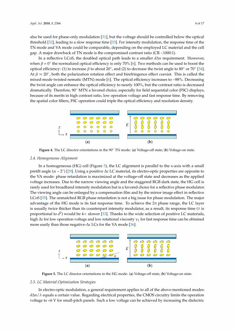
In a homogeneous (HG) cell (Figure 5), the LC alignment is parallel to the x-axis with a small pretilt angle (α ~ 2°) [29]. Using a positive Δε LC material, its electro-optic properties are opposite to the VA mode: phase retardation is maximized at the voltage-off state and decreases as the applied voltage increases. Due to the narrow viewing angle and the staggered RGB dark state, the HG cell is rarely used for broadband intensity modulation but is a favored choice for a reflective phase modulator. The viewing angle can be enlarged by a compensation film and by the mirror image effect in reflective LCoS [35]. The unmatched RGB phase retardation is not a big issue for phase modulation. The major advantage of the HG mode is its fast response time. To achieve the 2π phase range, the LC layer is usually twice thicker than its counterpart intensity modulator, as a result, its response time (τ is proportional to d2) would be 4x slower [33]. Thanks to the wide selection of positive LC materials, high Δε for low operation voltage and low rotational viscosity γ1 for fast response time can be obtained more easily than those negative-Δε LCs for the VA mode [36].
(a) (b)
Figure 5. The LC director orientations in the HG mode: (a) Voltage-off state; (b) Voltage-on state.
2.5. LC Material Optimization Strategies
In electro-optic modulation, a general requirement applies to all of the above-mentioned modes: dΔn/λ equals a certain value. Regarding electrical properties, the CMOS circuitry limits the operation voltage to <6 V for small-pitch panels. Such a low voltage can be achieved by increasing the dielectric anisotropy of LC materials, which could be obtained by applying lateral and terminal polar groups (such as F, CN, NCS, CF3 or OCF3) [37–39], polar CF2O bridges [40], and polar heterocycles [41,42]. However, these components often lead to a compromised nematic temperature range, lower solubility and higher viscosity γ1 [38]. Breaking this trade-off, the difluoromethoxy bridge (-CF2O)
Figure 4. The LC director orientations in the 90 TN mode: (a) Voltage-off state; (b) Voltage-on state.
2.4. Homogeneous Alignment
In a homogeneous (HG) cell (Figure 5), the LC alignment is parallel to the x-axis with a smallpretilt angle (α ~ 2) [29]. Using a positive ∆ε LC material, its electro-optic properties are opposite tothe VA mode: phase retardation is maximized at the voltage-off state and decreases as the appliedvoltage increases. Due to the narrow viewing angle and the staggered RGB dark state, the HG cell israrely used for broadband intensity modulation but is a favored choice for a reflective phase modulator.The viewing angle can be enlarged by a compensation film and by the mirror image effect in reflectiveLCoS [35]. The unmatched RGB phase retardation is not a big issue for phase modulation. The majoradvantage of the HG mode is its fast response time. To achieve the 2π phase range, the LC layeris usually twice thicker than its counterpart intensity modulator, as a result, its response time (τ isproportional to d2) would be 4× slower [33]. Thanks to the wide selection of positive LC materials,high ∆ε for low operation voltage and low rotational viscosity γ1 for fast response time can be obtainedmore easily than those negative-∆ε LCs for the VA mode [36].
Appl. Sci. 2018, 8, x FOR PEER REVIEW 4 of 18
the employed LC material and the cell gap. A major drawback of TN mode is the compromised contrast ratio (CR ~ 1000:1).
In a reflective LCoS, the doubled optical path leads to a smaller dΔn requirement. However, when β = 0° the normalized optical efficiency is only 70% [6]. Two methods can be used to boost the optical efficiency: (1) to increase β to about 20o, and (2) to decrease the twist angle to 80° or 70° [34]. At β ≈ 20°, both the polarization rotation effect and birefringence effect coexist. This is called the mixed-mode twisted nematic (MTN) mode [6]. The optical efficiency increases to ~88%. Decreasing the twist angle can enhance the optical efficiency to nearly 100%, but the contrast ratio is decreased dramatically. Therefore, 90° MTN a favored choice, especially for field sequential color (FSC) displays, because of its merits in high contrast ratio, low operation voltage and fast response time. By removing the spatial color filters, FSC operation could triple the optical efficiency and resolution density.
(a) (b)
Figure 4. The LC director orientations in the 90° TN mode: (a) Voltage-off state; (b) Voltage-on state.
2.4. Homogeneous Alignment
In a homogeneous (HG) cell (Figure 5), the LC alignment is parallel to the x-axis with a small pretilt angle (α ~ 2°) [29]. Using a positive Δε LC material, its electro-optic properties are opposite to the VA mode: phase retardation is maximized at the voltage-off state and decreases as the applied voltage increases. Due to the narrow viewing angle and the staggered RGB dark state, the HG cell is rarely used for broadband intensity modulation but is a favored choice for a reflective phase modulator. The viewing angle can be enlarged by a compensation film and by the mirror image effect in reflective LCoS [35]. The unmatched RGB phase retardation is not a big issue for phase modulation. The major advantage of the HG mode is its fast response time. To achieve the 2π phase range, the LC layer is usually twice thicker than its counterpart intensity modulator, as a result, its response time (τ is proportional to d2) would be 4x slower [33]. Thanks to the wide selection of positive LC materials, high Δε for low operation voltage and low rotational viscosity γ1 for fast response time can be obtained more easily than those negative-Δε LCs for the VA mode [36].
(a) (b)
Figure 5. The LC director orientations in the HG mode: (a) Voltage-off state; (b) Voltage-on state.
2.5. LC Material Optimization Strategies
In electro-optic modulation, a general requirement applies to all of the above-mentioned modes: dΔn/λ equals a certain value. Regarding electrical properties, the CMOS circuitry limits the operation voltage to <6 V for small-pitch panels. Such a low voltage can be achieved by increasing the dielectric anisotropy of LC materials, which could be obtained by applying lateral and terminal polar groups (such as F, CN, NCS, CF3 or OCF3) [37–39], polar CF2O bridges [40], and polar heterocycles [41,42]. However, these components often lead to a compromised nematic temperature range, lower solubility and higher viscosity γ1 [38]. Breaking this trade-off, the difluoromethoxy bridge (-CF2O)
Figure 5. The LC director orientations in the HG mode: (a) Voltage-off state; (b) Voltage-on state.
2.5. LC Material Optimization Strategies
In electro-optic modulation, a general requirement applies to all of the above-mentioned modes:d∆n/λ equals a certain value. Regarding electrical properties, the CMOS circuitry limits the operationvoltage to <6 V for small-pitch panels. Such a low voltage can be achieved by increasing the dielectric

Appl. Sci. 2018, 8, 2366 5 of 17
anisotropy of LC materials, which could be obtained by applying lateral and terminal polar groups(such as F, CN, NCS, CF3 or OCF3) [37–39], polar CF2O bridges [40], and polar heterocycles [41,42].However, these components often lead to a compromised nematic temperature range, lower solubilityand higher viscosity γ1 [38]. Breaking this trade-off, the difluoromethoxy bridge (-CF2O) [43] andisothiocyanato group (-NCS) [44,45] could improve ∆ε while retaining a reasonably low γ1. Whereasthe former breaks the molecular π-π conjugation resulting in a low ∆n, and the latter gives rise tothe annoying charge accumulation effect, which degrades the voltage holding ratio. Here comes thesecond consideration on electrical properties—the resistivity which determines the voltage holdingratio. Although LCoS devices demand a lower LC resistivity (>1012 Ω·cm) than the active matrixdisplays (>1013 Ω·cm) [46,47], it still limits the LC component selection. Compounds with a large ∆ε
would require multiple dipoles, which may lead to a compromised γ1.From the aspect of device configuration, a thinner cell gap helps gain fast response time with
the adoption of a slightly higher ∆n LC. To be noticed, the toughest color to achieve the 2π phasemodulation is red because of the longest wavelength and the lowest birefringence. Various terphenylsand tolanes have been developed for high ∆n LCs [48,49]. Although many precise modificationsof the molecular chemical structures have been mentioned [50–52], such as shifting the location ofthe mesomorphic core, introducing the lateral substituents into different positions and the variousterminals, the high γ1 of terphenyls and the poor UV stability of tolanes remains unsolved [53]. Thoseare the properties not intended to be compromised. Additionally, the voltage shielding effect byalignment layer reduces the effective voltage applied to the LC layer in thin cells [54,55]. In summary,a delicate balance should be reached between high birefringence, high dielectric anisotropy, low meltingpoint, low viscosity, high resistivity, and good UV stability according to the device configuration. Thestate-of-the-art LC material development reaches a submillisecond response time for VA [56–58] andMTN [46,59] LCoS at 40 C, and a ~2 ms response time for 2π phase modulation [46,47]. More thanthat, these optimization strategies and the developed materials could be applied to other LC phasemodulation-based devices such as tunable lenses, scanners, tunable filters, and optically addressedspatial light modulators [60–64], which may be incorporated in AR systems in other ways.
3. Fringing Field Effect and Novel Solution
To optimize the optical performance of LCoS systematically, several research groups have devotedefforts in device modeling [65–67]. However, until recently, the fringing field effect (FFE) still remainsthe major issue to be tackled with [68–73]. In order to display greyscale images, different pixels couldhave different voltages. The unequal voltages on adjacent pixels give rises to FFE. As Figure 6 depicts,when a bright pixel is adjacent to two dark pixels, a dark split region may appear in the bright pixelarea, and light leakage arises at the edge of the dark pixel, leading to display luminance loss andreduced contrast ratio. The severity of FFE depends on the display mode and the device configuration.Generally speaking, VA has the strongest FFE, resulting in a ~30% luminance loss; 90 MTN is theleast sensitive to FFE; while the HG mode is a favored choice for phase modulation. Figure 6 showsthe FFE of VA mode with different pixel sizes and cell gap. Because of the small inter-pixel gap, LCson the pixel edge experience strong horizontal electric field, giving rise to phase distortion. Thisphenomenon is not obvious in direct-view transmissive LCDs because the inter-pixel region is coveredby a large-area black matrix (>5 µm). The asymmetry of phase retardation/reflection is determinedby the alignment direction of the pretilt angle. In Figure 6a, the same resolution density is compared,which is determined by pixel pitch p. With a thinner cell gap d, the FFE-affected region is compressedto a narrower edge. Applying this thin cell strategy [69,70], the cell gap in VA LCoS is optimized tod < 2 µm [73].
FFE is especially pronounced in small-pitch LCoS devices [69], which is highly desirable inaugmented reality applications. Because of the reduced pixel pitch and cell gap (p/d) ratio, theunwanted horizontal electric field is strengthened [70]. This can be seen from Figure 6b: whenthe resolution density is doubled (p changes from 16 µm to 8 µm), the absolute FFE width w is

Appl. Sci. 2018, 8, 2366 6 of 17
relatively stable, while the ratio of the FFE-affected region increases dramatically. Several methodshave been proposed to reduce FFE. In 2002, Fan-Chiang et al. explored how sloped electrodes helpreduce FFE with quantitative exploration [68]. An optimal electrode slope of 1 was demonstratedfor 80 MTN cell and 45 TN cell, while the VA and HG modes call for further improvement. In thesame year, a finger-on-plane type common electrode was designed to eliminate the pixel-splittingphenomenon [74]. Whereas the diffraction effect and relatively low optical efficiency hinder itswidespread applications [69]. In 2005, Gu et al. minimized FFE by a double-sided electrode design,where the requirements of dual TFTs and pixel registration brings manufacturing challenges [75]. Later,Fan-Chiang et al. proposed to adopt circularly polarized light in the VA mode for FFE suppression [69].Though an impressively high optical efficiency and fast dynamic response were demonstrated, hardlycan this method be integrated into the preferred normally black reflective VA mode. In other words,the contrast ratio is compromised. In 2015, Li et al. adopted non-rectangular pixel electrodes forpixel edge FFE compensation [76]. This design works well on large pixels while the degree ofstructural modification is constrained on small-pitch configurations. To satisfy the urgent needof FFE reduction on small-pitch LCoS devices, here, we propose a novel design of patterned pretiltangle control [77–79]. The formed inhomogeneous LC director distribution could oppose the FFEinduced by neighboring pixels.
Appl. Sci. 2018, 8, x FOR PEER REVIEW 6 of 18
[74]. Whereas the diffraction effect and relatively low optical efficiency hinder its widespread applications [69]. In 2005, Gu et al. minimized FFE by a double-sided electrode design, where the requirements of dual TFTs and pixel registration brings manufacturing challenges [75]. Later, Fan-Chiang et al. proposed to adopt circularly polarized light in the VA mode for FFE suppression [69]. Though an impressively high optical efficiency and fast dynamic response were demonstrated, hardly can this method be integrated into the preferred normally black reflective VA mode. In other words, the contrast ratio is compromised. In 2015, Li et al. adopted non-rectangular pixel electrodes for pixel edge FFE compensation [76]. This design works well on large pixels while the degree of structural modification is constrained on small-pitch configurations. To satisfy the urgent need of FFE reduction on small-pitch LCoS devices, here, we propose a novel design of patterned pretilt angle control [77–79]. The formed inhomogeneous LC director distribution could oppose the FFE induced by neighboring pixels.
(a) (b) Figure 6. The fringing field effect (FFE) of a VA cell: (a) cell gap effect; (b) pixel pitch effect. p, d, and w stand for pixel pitch, cell gap, and FFE border width, respectively (unit: μm).
3.1. Pretilt Angle Pattern Determining Method
The basic concept of our design is to find an optimized pretilt angle pattern for minimizing FFE. The initial step is to identify the phase retardation profile as a function of location in the pixel region. Since FFE is most pronounced when the largest voltage difference occurs between adjacent pixel electrodes, two worst scenarios are used in our evaluation and optimization. These are (1) maximum operation voltage applied to the central pixel electrode while minimum operation voltage applied to the adjacent pixel electrodes; and (2) minimum operation voltage for the central pixel while the maximum voltage for the neighboring ones.
Figure 6. The fringing field effect (FFE) of a VA cell: (a) cell gap effect; (b) pixel pitch effect. p, d, and wstand for pixel pitch, cell gap, and FFE border width, respectively (unit: µm).
3.1. Pretilt Angle Pattern Determining Method
The basic concept of our design is to find an optimized pretilt angle pattern for minimizing FFE.The initial step is to identify the phase retardation profile as a function of location in the pixel region.Since FFE is most pronounced when the largest voltage difference occurs between adjacent pixelelectrodes, two worst scenarios are used in our evaluation and optimization. These are (1) maximumoperation voltage applied to the central pixel electrode while minimum operation voltage appliedto the adjacent pixel electrodes; and (2) minimum operation voltage for the central pixel while themaximum voltage for the neighboring ones.
After basic evaluation, there are two determining methods to optimize the pretilt angle pattern.The first is to control the phase retardation error over the whole pixel region within a predeterminedpercentage level. As a general determining approach, the lack of a convergent solution makes theoptimization complicated, and the iterative algorism results in heavy computation loads. Therefore,here we introduce the second determining method. As shown in Figure 6b, based on the initiallyidentified phase retardation profile, we divide the pixel region into two zones with an FFE borderwidth w. From Figure 7, we can see that the pretilt angle of the inner zone and outer zone is optimized
Appl. Sci. 2018, 8, 2366 7 of 17
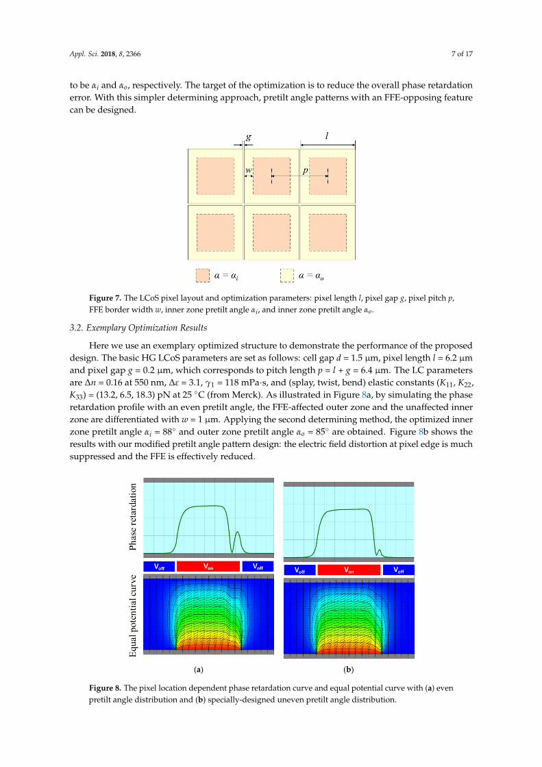
to be αi and αo, respectively. The target of the optimization is to reduce the overall phase retardationerror. With this simpler determining approach, pretilt angle patterns with an FFE-opposing featurecan be designed.Appl. Sci. 2018, 8, x FOR PEER REVIEW 7 of 18
Figure 7. The LCoS pixel layout and optimization parameters: pixel length l, pixel gap g, pixel pitch p, FFE border width w, inner zone pretilt angle αi, and inner zone pretilt angle αo.
After basic evaluation, there are two determining methods to optimize the pretilt angle pattern. The first is to control the phase retardation error over the whole pixel region within a predetermined percentage level. As a general determining approach, the lack of a convergent solution makes the optimization complicated, and the iterative algorism results in heavy computation loads. Therefore, here we introduce the second determining method. As shown in Figure 6b, based on the initially identified phase retardation profile, we divide the pixel region into two zones with an FFE border width w. From Figure 7, we can see that the pretilt angle of the inner zone and outer zone is optimized to be αi and αo, respectively. The target of the optimization is to reduce the overall phase retardation error. With this simpler determining approach, pretilt angle patterns with an FFE-opposing feature can be designed.
3.2. Exemplary Optimization Results
Here we use an exemplary optimized structure to demonstrate the performance of the proposed design. The basic HG LCoS parameters are set as follows: cell gap d = 1.5 μm, pixel length l = 6.2 μm and pixel gap g = 0.2 μm, which corresponds to pitch length p = l + g = 6.4 μm. The LC parameters are Δn = 0.16 at 550 nm, Δε = 3.1, γ1 = 118 mPa·s, and (splay, twist, bend) elastic constants (K11, K22, K33) = (13.2, 6.5, 18.3) pN at 25 °C (from Merck). As illustrated in Figure 8a, by simulating the phase retardation profile with an even pretilt angle, the FFE-affected outer zone and the unaffected inner zone are differentiated with w = 1 μm. Applying the second determining method, the optimized inner zone pretilt angle αi = 88° and outer zone pretilt angle αo = 85° are obtained. Figure 8b shows the results with our modified pretilt angle pattern design: the electric field distortion at pixel edge is much suppressed and the FFE is effectively reduced.
Figure 7. The LCoS pixel layout and optimization parameters: pixel length l, pixel gap g, pixel pitch p,FFE border width w, inner zone pretilt angle αi, and inner zone pretilt angle αo.
3.2. Exemplary Optimization Results
Here we use an exemplary optimized structure to demonstrate the performance of the proposeddesign. The basic HG LCoS parameters are set as follows: cell gap d = 1.5 µm, pixel length l = 6.2 µmand pixel gap g = 0.2 µm, which corresponds to pitch length p = l + g = 6.4 µm. The LC parametersare ∆n = 0.16 at 550 nm, ∆ε = 3.1, γ1 = 118 mPa·s, and (splay, twist, bend) elastic constants (K11, K22,K33) = (13.2, 6.5, 18.3) pN at 25 C (from Merck). As illustrated in Figure 8a, by simulating the phaseretardation profile with an even pretilt angle, the FFE-affected outer zone and the unaffected innerzone are differentiated with w = 1 µm. Applying the second determining method, the optimized innerzone pretilt angle αi = 88 and outer zone pretilt angle αo = 85 are obtained. Figure 8b shows theresults with our modified pretilt angle pattern design: the electric field distortion at pixel edge is muchsuppressed and the FFE is effectively reduced.
Appl. Sci. 2018, 8, x FOR PEER REVIEW 8 of 18
(a) (b)
Figure 8. The pixel location dependent phase retardation curve and equal potential curve with (a) even pretilt angle distribution and (b) specially-designed uneven pretilt angle distribution.
One potential concern of our design is the phase retardation uniformity when an equal voltage is applied to adjacent pixel electrodes. Therefore, we plot the phase retardation curves with our special pretilt angle design. From Figure 9a we can see, in the large pretilt angle region (α > 80°), that neither phase retardation nor reflectance is sensitive to the pretilt angle. In Figure 9b, generally flat spatial profiles are obtained in our design. The spatial fluctuation at all-pixels-dark state is only ΔΓ = Γ (α = 85°) − Γ (α = 88°) = 0.01π for phase retardation and R (α = 85°) − R (α = 88°) = 0.03% for reflectance, suggesting that a high contrast ratio could be maintained. At all-pixels-bright state, the reflectance fluctuation is within 0.002%. In other words, the side effect of our proposed design is negligible compared to the gain in FFE reduction.
(a) (b)
Figure 9. (a) The pretilt angle dependent phase retardations. (b) Spatial phase retardation uniformity at voltage-off state.
3.3. Fabrication Method
The pretilt angle pattern can be realized by a photoalignment layer, which provides inhomogeneous anchoring energy distribution. Two methods have been proposed to realize the spatial variant pretilt angle control by Kwok’s group. In 2011, the stack of a horizontal alignment polymer on a vertical alignment layer was reported [80]. By controlling the dosage of UV light exposure, the degree of polymerization can be adjusted spatially. After rinsing away the unexposed
Figure 8. The pixel location dependent phase retardation curve and equal potential curve with (a) evenpretilt angle distribution and (b) specially-designed uneven pretilt angle distribution.

Appl. Sci. 2018, 8, 2366 8 of 17
One potential concern of our design is the phase retardation uniformity when an equal voltageis applied to adjacent pixel electrodes. Therefore, we plot the phase retardation curves with ourspecial pretilt angle design. From Figure 9a we can see, in the large pretilt angle region (α > 80),that neither phase retardation nor reflectance is sensitive to the pretilt angle. In Figure 9b, generallyflat spatial profiles are obtained in our design. The spatial fluctuation at all-pixels-dark state is only∆Γ = Γ (α = 85) − Γ (α = 88) = 0.01π for phase retardation and R (α = 85) − R (α = 88) = 0.03%for reflectance, suggesting that a high contrast ratio could be maintained. At all-pixels-bright state,the reflectance fluctuation is within 0.002%. In other words, the side effect of our proposed design isnegligible compared to the gain in FFE reduction.
Appl. Sci. 2018, 8, x FOR PEER REVIEW 8 of 18
(a) (b)
Figure 8. The pixel location dependent phase retardation curve and equal potential curve with (a) even pretilt angle distribution and (b) specially-designed uneven pretilt angle distribution.
One potential concern of our design is the phase retardation uniformity when an equal voltage is applied to adjacent pixel electrodes. Therefore, we plot the phase retardation curves with our special pretilt angle design. From Figure 9a we can see, in the large pretilt angle region (α > 80°), that neither phase retardation nor reflectance is sensitive to the pretilt angle. In Figure 9b, generally flat spatial profiles are obtained in our design. The spatial fluctuation at all-pixels-dark state is only ΔΓ = Γ (α = 85°) − Γ (α = 88°) = 0.01π for phase retardation and R (α = 85°) − R (α = 88°) = 0.03% for reflectance, suggesting that a high contrast ratio could be maintained. At all-pixels-bright state, the reflectance fluctuation is within 0.002%. In other words, the side effect of our proposed design is negligible compared to the gain in FFE reduction.
(a) (b)
Figure 9. (a) The pretilt angle dependent phase retardations. (b) Spatial phase retardation uniformity at voltage-off state.
3.3. Fabrication Method
The pretilt angle pattern can be realized by a photoalignment layer, which provides inhomogeneous anchoring energy distribution. Two methods have been proposed to realize the spatial variant pretilt angle control by Kwok’s group. In 2011, the stack of a horizontal alignment polymer on a vertical alignment layer was reported [80]. By controlling the dosage of UV light exposure, the degree of polymerization can be adjusted spatially. After rinsing away the unexposed
Figure 9. (a) The pretilt angle dependent phase retardations. (b) Spatial phase retardation uniformityat voltage-off state.
3.3. Fabrication Method
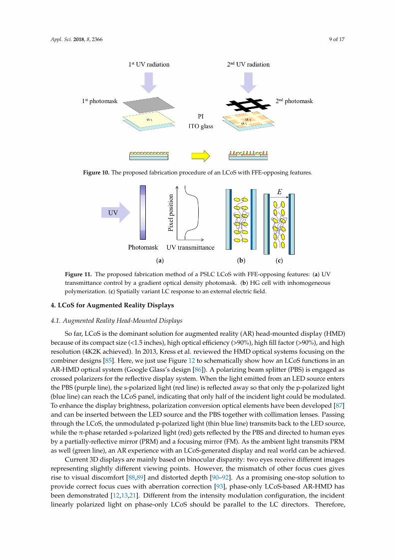
The pretilt angle pattern can be realized by a photoalignment layer, which providesinhomogeneous anchoring energy distribution. Two methods have been proposed to realize thespatial variant pretilt angle control by Kwok’s group. In 2011, the stack of a horizontal alignmentpolymer on a vertical alignment layer was reported [80]. By controlling the dosage of UV lightexposure, the degree of polymerization can be adjusted spatially. After rinsing away the unexposedarea, the ratio of polymerized homogeneous alignment domain and exposed vertical alignment domaincoordinately determine the local LC pretilt angle. In 2013, Fan et al. reported a new alignment materialwhich enables direct UV patterning on a pretilt angle [81]. Based on the above-mentioned methods,a two-step manufacturing process can generate FFE-opposing features (Figure 10): (1) A uniform pretiltangle α1 is produced on the polyimide (PI) alignment layer on ITO glass by uniform UV irradiation;(2) A second photomask for selective UV exposure is added to differentiate the pretilt angle αi in innerzone and αo in outer zone. If the alignment layer is replaced by silicon oxide [82], an e-beam treatmentcan be adopted for the patterning.
For infrared spatial light modulators, the patterned pretilt angle and anchoring energy can alsobe achieved on the polymer-stabilized liquid crystal (PSLC) [83,84]. First, an LC-monomer mixedprecursor is prepared and filled in the LCoS panel. Second, a photomask with gradient optical densityis required to generate spatially variant UV light intensity. The UV light irradiated on the LC layer ismore intense in the center region than at the pixel edge, therefore, in the center, it generates a higherdegree of polymerization. Through this spatially variant polymerization process, an inhomogeneouspretilt angle and anchoring energy distribution can be formed, as Figure 11 illustrates.
Appl. Sci. 2018, 8, 2366 9 of 17
Appl. Sci. 2018, 8, x FOR PEER REVIEW 9 of 18
area, the ratio of polymerized homogeneous alignment domain and exposed vertical alignment domain coordinately determine the local LC pretilt angle. In 2013, Fan et al. reported a new alignment material which enables direct UV patterning on a pretilt angle [81]. Based on the above-mentioned methods, a two-step manufacturing process can generate FFE-opposing features (Figure 10): (1) A uniform pretilt angle α1 is produced on the polyimide (PI) alignment layer on ITO glass by uniform UV irradiation; (2) A second photomask for selective UV exposure is added to differentiate the pretilt angle αi in inner zone and αo in outer zone. If the alignment layer is replaced by silicon oxide [82], an e-beam treatment can be adopted for the patterning.
Figure 10. The proposed fabrication procedure of an LCoS with FFE-opposing features.
For infrared spatial light modulators, the patterned pretilt angle and anchoring energy can also be achieved on the polymer-stabilized liquid crystal (PSLC) [83,84]. First, an LC-monomer mixed precursor is prepared and filled in the LCoS panel. Second, a photomask with gradient optical density is required to generate spatially variant UV light intensity. The UV light irradiated on the LC layer is more intense in the center region than at the pixel edge, therefore, in the center, it generates a higher degree of polymerization. Through this spatially variant polymerization process, an inhomogeneous pretilt angle and anchoring energy distribution can be formed, as Figure 11 illustrates.
(a) (b) (c)
Figure 11. The proposed fabrication method of a PSLC LCoS with FFE-opposing features: (a) UV transmittance control by a gradient optical density photomask. (b) HG cell with inhomogeneous polymerization. (c) Spatially variant LC response to an external electric field.
4. LCoS for Augmented Reality Displays
4.1. Augmented Reality Head-Mounted Displays
So far, LCoS is the dominant solution for augmented reality (AR) head-mounted display (HMD) because of its compact size (<1.5 inches), high optical efficiency (>90%), high fill factor (>90%), and high resolution (4K2K achieved). In 2013, Kress et al. reviewed the HMD optical systems focusing on the combiner designs [85]. Here, we just use Figure 12 to schematically show how an LCoS functions in an AR-HMD optical system (Google Glass’s design [86]). A polarizing beam splitter (PBS) is
Figure 10. The proposed fabrication procedure of an LCoS with FFE-opposing features.
Appl. Sci. 2018, 8, x FOR PEER REVIEW 9 of 18
area, the ratio of polymerized homogeneous alignment domain and exposed vertical alignment domain coordinately determine the local LC pretilt angle. In 2013, Fan et al. reported a new alignment material which enables direct UV patterning on a pretilt angle [81]. Based on the above-mentioned methods, a two-step manufacturing process can generate FFE-opposing features (Figure 10): (1) A uniform pretilt angle α1 is produced on the polyimide (PI) alignment layer on ITO glass by uniform UV irradiation; (2) A second photomask for selective UV exposure is added to differentiate the pretilt angle αi in inner zone and αo in outer zone. If the alignment layer is replaced by silicon oxide [82], an e-beam treatment can be adopted for the patterning.
Figure 10. The proposed fabrication procedure of an LCoS with FFE-opposing features.
For infrared spatial light modulators, the patterned pretilt angle and anchoring energy can also be achieved on the polymer-stabilized liquid crystal (PSLC) [83,84]. First, an LC-monomer mixed precursor is prepared and filled in the LCoS panel. Second, a photomask with gradient optical density is required to generate spatially variant UV light intensity. The UV light irradiated on the LC layer is more intense in the center region than at the pixel edge, therefore, in the center, it generates a higher degree of polymerization. Through this spatially variant polymerization process, an inhomogeneous pretilt angle and anchoring energy distribution can be formed, as Figure 11 illustrates.
(a) (b) (c)
Figure 11. The proposed fabrication method of a PSLC LCoS with FFE-opposing features: (a) UV transmittance control by a gradient optical density photomask. (b) HG cell with inhomogeneous polymerization. (c) Spatially variant LC response to an external electric field.
4. LCoS for Augmented Reality Displays
4.1. Augmented Reality Head-Mounted Displays
So far, LCoS is the dominant solution for augmented reality (AR) head-mounted display (HMD) because of its compact size (<1.5 inches), high optical efficiency (>90%), high fill factor (>90%), and high resolution (4K2K achieved). In 2013, Kress et al. reviewed the HMD optical systems focusing on the combiner designs [85]. Here, we just use Figure 12 to schematically show how an LCoS functions in an AR-HMD optical system (Google Glass’s design [86]). A polarizing beam splitter (PBS) is
Figure 11. The proposed fabrication method of a PSLC LCoS with FFE-opposing features: (a) UVtransmittance control by a gradient optical density photomask. (b) HG cell with inhomogeneouspolymerization. (c) Spatially variant LC response to an external electric field.
4. LCoS for Augmented Reality Displays
4.1. Augmented Reality Head-Mounted Displays
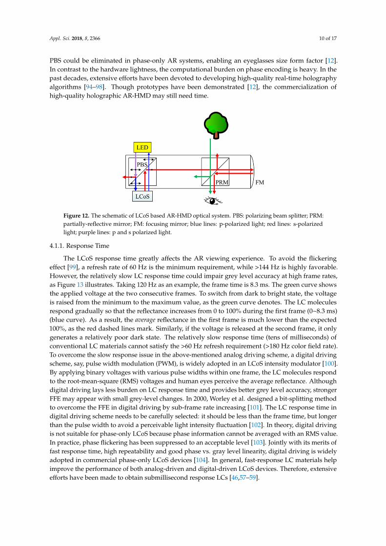
So far, LCoS is the dominant solution for augmented reality (AR) head-mounted display (HMD)because of its compact size (<1.5 inches), high optical efficiency (>90%), high fill factor (>90%), and highresolution (4K2K achieved). In 2013, Kress et al. reviewed the HMD optical systems focusing on thecombiner designs [85]. Here, we just use Figure 12 to schematically show how an LCoS functions in anAR-HMD optical system (Google Glass’s design [86]). A polarizing beam splitter (PBS) is engaged ascrossed polarizers for the reflective display system. When the light emitted from an LED source entersthe PBS (purple line), the s-polarized light (red line) is reflected away so that only the p-polarized light(blue line) can reach the LCoS panel, indicating that only half of the incident light could be modulated.To enhance the display brightness, polarization conversion optical elements have been developed [87]and can be inserted between the LED source and the PBS together with collimation lenses. Passingthrough the LCoS, the unmodulated p-polarized light (thin blue line) transmits back to the LED source,while the π-phase retarded s-polarized light (red) gets reflected by the PBS and directed to human eyesby a partially-reflective mirror (PRM) and a focusing mirror (FM). As the ambient light transmits PRMas well (green line), an AR experience with an LCoS-generated display and real world can be achieved.
Current 3D displays are mainly based on binocular disparity: two eyes receive different imagesrepresenting slightly different viewing points. However, the mismatch of other focus cues givesrise to visual discomfort [88,89] and distorted depth [90–92]. As a promising one-stop solution toprovide correct focus cues with aberration correction [93], phase-only LCoS-based AR-HMD hasbeen demonstrated [12,13,21]. Different from the intensity modulation configuration, the incidentlinearly polarized light on phase-only LCoS should be parallel to the LC directors. Therefore,
Appl. Sci. 2018, 8, 2366 10 of 17
PBS could be eliminated in phase-only AR systems, enabling an eyeglasses size form factor [12].In contrast to the hardware lightness, the computational burden on phase encoding is heavy. In thepast decades, extensive efforts have been devoted to developing high-quality real-time holographyalgorithms [94–98]. Though prototypes have been demonstrated [12], the commercialization ofhigh-quality holographic AR-HMD may still need time.
Appl. Sci. 2018, 8, x FOR PEER REVIEW 10 of 18
engaged as crossed polarizers for the reflective display system. When the light emitted from an LED source enters the PBS (purple line), the s-polarized light (red line) is reflected away so that only the p-polarized light (blue line) can reach the LCoS panel, indicating that only half of the incident light could be modulated. To enhance the display brightness, polarization conversion optical elements have been developed [87] and can be inserted between the LED source and the PBS together with collimation lenses. Passing through the LCoS, the unmodulated p-polarized light (thin blue line) transmits back to the LED source, while the π-phase retarded s-polarized light (red) gets reflected by the PBS and directed to human eyes by a partially-reflective mirror (PRM) and a focusing mirror (FM). As the ambient light transmits PRM as well (green line), an AR experience with an LCoS-generated display and real world can be achieved.
Figure 12. The schematic of LCoS based AR-HUD optical system. BLU: backlight unit; PBS: polarizing beam splitter; PRM: partially-reflective mirror; FM: focusing mirror; blue lines: p-polarized light; red lines: s-polarized light; purple lines: p and s polarized light.
Current 3D displays are mainly based on binocular disparity: two eyes receive different images representing slightly different viewing points. However, the mismatch of other focus cues gives rise to visual discomfort [88,89] and distorted depth [90–92]. As a promising one-stop solution to provide correct focus cues with aberration correction [93], phase-only LCoS-based AR-HMD has been demonstrated [12,13,21]. Different from the intensity modulation configuration, the incident linearly polarized light on phase-only LCoS should be parallel to the LC directors. Therefore, PBS could be eliminated in phase-only AR systems, enabling an eyeglasses size form factor [12]. In contrast to the hardware lightness, the computational burden on phase encoding is heavy. In the past decades, extensive efforts have been devoted to developing high-quality real-time holography algorithms [94–98]. Though prototypes have been demonstrated [12], the commercialization of high-quality holographic AR-HMD may still need time.
4.1.1. Response Time
The LCoS response time greatly affects the AR viewing experience. To avoid the flickering effect [99], a refresh rate of 60 Hz is the minimum requirement, while >144 Hz is highly favorable. However, the relatively slow LC response time could impair grey level accuracy at high frame rates, as Figure 13 illustrates. Taking 120 Hz as an example, the frame time is 8.3 ms. The green curve shows the applied voltage at the two consecutive frames. To switch from dark to bright state, the voltage is raised from the minimum to the maximum value, as the green curve denotes. The LC molecules respond gradually so that the reflectance increases from 0 to 100% during the first frame (0~8.3 ms) (blue curve). As a result, the average reflectance in the first frame is much lower than the expected 100%, as the red dashed lines mark. Similarly, if the voltage is released at the second frame, it only generates a relatively poor dark state. The relatively slow response time (tens of milliseconds) of conventional LC materials cannot satisfy the >60 Hz refresh requirement (>180 Hz color field rate). To overcome the slow response issue in the above-mentioned analog driving scheme, a digital driving scheme, say, pulse width modulation (PWM), is widely adopted in an LCoS intensity
Figure 12. The schematic of LCoS based AR-HMD optical system. PBS: polarizing beam splitter; PRM:partially-reflective mirror; FM: focusing mirror; blue lines: p-polarized light; red lines: s-polarizedlight; purple lines: p and s polarized light.
4.1.1. Response Time
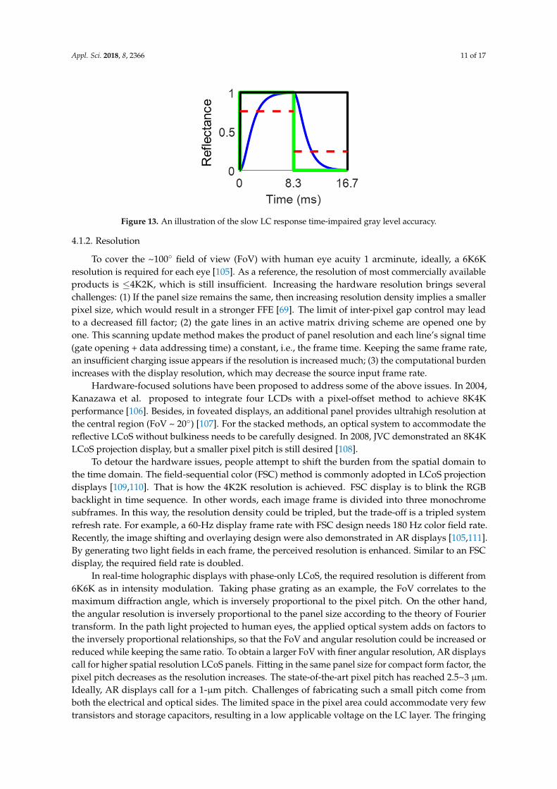
The LCoS response time greatly affects the AR viewing experience. To avoid the flickeringeffect [99], a refresh rate of 60 Hz is the minimum requirement, while >144 Hz is highly favorable.However, the relatively slow LC response time could impair grey level accuracy at high frame rates,as Figure 13 illustrates. Taking 120 Hz as an example, the frame time is 8.3 ms. The green curve showsthe applied voltage at the two consecutive frames. To switch from dark to bright state, the voltageis raised from the minimum to the maximum value, as the green curve denotes. The LC moleculesrespond gradually so that the reflectance increases from 0 to 100% during the first frame (0~8.3 ms)(blue curve). As a result, the average reflectance in the first frame is much lower than the expected100%, as the red dashed lines mark. Similarly, if the voltage is released at the second frame, it onlygenerates a relatively poor dark state. The relatively slow response time (tens of milliseconds) ofconventional LC materials cannot satisfy the >60 Hz refresh requirement (>180 Hz color field rate).To overcome the slow response issue in the above-mentioned analog driving scheme, a digital drivingscheme, say, pulse width modulation (PWM), is widely adopted in an LCoS intensity modulator [100].By applying binary voltages with various pulse widths within one frame, the LC molecules respondto the root-mean-square (RMS) voltages and human eyes perceive the average reflectance. Althoughdigital driving lays less burden on LC response time and provides better grey level accuracy, strongerFFE may appear with small grey-level changes. In 2000, Worley et al. designed a bit-splitting methodto overcome the FFE in digital driving by sub-frame rate increasing [101]. The LC response time indigital driving scheme needs to be carefully selected: it should be less than the frame time, but longerthan the pulse width to avoid a perceivable light intensity fluctuation [102]. In theory, digital drivingis not suitable for phase-only LCoS because phase information cannot be averaged with an RMS value.In practice, phase flickering has been suppressed to an acceptable level [103]. Jointly with its merits offast response time, high repeatability and good phase vs. gray level linearity, digital driving is widelyadopted in commercial phase-only LCoS devices [104]. In general, fast-response LC materials helpimprove the performance of both analog-driven and digital-driven LCoS devices. Therefore, extensiveefforts have been made to obtain submillisecond response LCs [46,57–59].
Appl. Sci. 2018, 8, 2366 11 of 17
Appl. Sci. 2018, 8, x FOR PEER REVIEW 11 of 18
modulator [100]. By applying binary voltages with various pulse widths within one frame, the LC molecules respond to the root-mean-square (RMS) voltages and human eyes perceive the average reflectance. Although digital driving lays less burden on LC response time and provides better grey level accuracy, stronger FFE may appear with small grey-level changes. In 2000, Worley et al. designed a bit-splitting method to overcome the FFE in digital driving by sub-frame rate increasing [101]. The LC response time in digital driving scheme needs to be carefully selected: it should be less than the frame time, but longer than the pulse width to avoid a perceivable light intensity fluctuation [102]. In theory, digital driving is not suitable for phase-only LCoS because phase information cannot be averaged with an RMS value. In practice, phase flickering has been suppressed to an acceptable level [103]. Jointly with its merits of fast response time, high repeatability and good phase vs. gray level linearity, digital driving is widely adopted in commercial phase-only LCoS devices [104]. In general, fast-response LC materials help improve the performance of both analog-driven and digital-driven LCoS devices. Therefore, extensive efforts have been made to obtain submillisecond response LCs [46,57–59].
Figure 13. An illustration of the slow LC response time-impaired gray level accuracy.
4.1.2. Resolution
To cover the ~100° field of view (FoV) with human eye acuity 1 arcminute, ideally, a 6K6K resolution is required for each eye [105]. As a reference, the resolution of most commercially available products is ≤4K2K, which is still insufficient. Increasing the hardware resolution brings several challenges: (1) If the panel size remains the same, then increasing resolution density implies a smaller pixel size, which would result in a stronger FFE [69]. The limit of inter-pixel gap control may lead to a decreased fill factor; (2) the gate lines in an active matrix driving scheme are opened one by one. This scanning update method makes the product of panel resolution and each line’s signal time (gate opening + data addressing time) a constant, i.e., the frame time. Keeping the same frame rate, an insufficient charging issue appears if the resolution is increased much; (3) the computational burden increases with the display resolution, which may decrease the source input frame rate.
Hardware-focused solutions have been proposed to address some of the above issues. In 2004, Kanazawa et al. proposed to integrate four LCDs with a pixel-offset method to achieve 8K4K performance [106]. Besides, in foveated displays, an additional panel provides ultrahigh resolution at the central region (FoV ~ 20°) [107]. For the stacked methods, an optical system to accommodate the reflective LCoS without bulkiness needs to be carefully designed. In 2008, JVC demonstrated an 8K4K LCoS projection display, but a smaller pixel pitch is still desired [108].
To detour the hardware issues, people attempt to shift the burden from the spatial domain to the time domain. The field-sequential color (FSC) method is commonly adopted in LCoS projection displays [109,110]. That is how the 4K2K resolution is achieved. FSC display is to blink the RGB backlight in time sequence. In other words, each image frame is divided into three monochrome subframes. In this way, the resolution density could be tripled, but the trade-off is a tripled system refresh rate. For example, a 60-Hz display frame rate with FSC design needs 180 Hz color field rate. Recently, the image shifting and overlaying design were also demonstrated in AR displays [105,111].
Figure 13. An illustration of the slow LC response time-impaired gray level accuracy.
4.1.2. Resolution
To cover the ~100 field of view (FoV) with human eye acuity 1 arcminute, ideally, a 6K6Kresolution is required for each eye [105]. As a reference, the resolution of most commercially availableproducts is ≤4K2K, which is still insufficient. Increasing the hardware resolution brings severalchallenges: (1) If the panel size remains the same, then increasing resolution density implies a smallerpixel size, which would result in a stronger FFE [69]. The limit of inter-pixel gap control may leadto a decreased fill factor; (2) the gate lines in an active matrix driving scheme are opened one byone. This scanning update method makes the product of panel resolution and each line’s signal time(gate opening + data addressing time) a constant, i.e., the frame time. Keeping the same frame rate,an insufficient charging issue appears if the resolution is increased much; (3) the computational burdenincreases with the display resolution, which may decrease the source input frame rate.
Hardware-focused solutions have been proposed to address some of the above issues. In 2004,Kanazawa et al. proposed to integrate four LCDs with a pixel-offset method to achieve 8K4Kperformance [106]. Besides, in foveated displays, an additional panel provides ultrahigh resolution atthe central region (FoV ~ 20) [107]. For the stacked methods, an optical system to accommodate thereflective LCoS without bulkiness needs to be carefully designed. In 2008, JVC demonstrated an 8K4KLCoS projection display, but a smaller pixel pitch is still desired [108].
To detour the hardware issues, people attempt to shift the burden from the spatial domain tothe time domain. The field-sequential color (FSC) method is commonly adopted in LCoS projectiondisplays [109,110]. That is how the 4K2K resolution is achieved. FSC display is to blink the RGBbacklight in time sequence. In other words, each image frame is divided into three monochromesubframes. In this way, the resolution density could be tripled, but the trade-off is a tripled systemrefresh rate. For example, a 60-Hz display frame rate with FSC design needs 180 Hz color field rate.Recently, the image shifting and overlaying design were also demonstrated in AR displays [105,111].By generating two light fields in each frame, the perceived resolution is enhanced. Similar to an FSCdisplay, the required field rate is doubled.
In real-time holographic displays with phase-only LCoS, the required resolution is different from6K6K as in intensity modulation. Taking phase grating as an example, the FoV correlates to themaximum diffraction angle, which is inversely proportional to the pixel pitch. On the other hand,the angular resolution is inversely proportional to the panel size according to the theory of Fouriertransform. In the path light projected to human eyes, the applied optical system adds on factors tothe inversely proportional relationships, so that the FoV and angular resolution could be increased orreduced while keeping the same ratio. To obtain a larger FoV with finer angular resolution, AR displayscall for higher spatial resolution LCoS panels. Fitting in the same panel size for compact form factor, thepixel pitch decreases as the resolution increases. The state-of-the-art pixel pitch has reached 2.5~3 µm.Ideally, AR displays call for a 1-µm pitch. Challenges of fabricating such a small pitch come fromboth the electrical and optical sides. The limited space in the pixel area could accommodate very fewtransistors and storage capacitors, resulting in a low applicable voltage on the LC layer. The fringing

Appl. Sci. 2018, 8, 2366 12 of 17
field effect and low fill factor impair the throughput optical power. Presently, the relatively large pixelsize and limited resolution provided by commercial LCoS panels cannot provide a satisfactory 3Dimage quality. An upgrade in hardware or new optical system design is highly desirable.
4.2. Augmented Reality Head-Up Displays
Head-up display (HUD) was first developed for military aircraft. Nowadays, it is extended toautomobile driving assistance. By projecting a virtual image onto the windshield, the driver doesnot need to head down to watch for the information displayed on the cockpit cluster. In so doing,the distraction could be minimized. A schematic of today’s HUD is shown in Figure 14. By using adouble mirror (M1 and M2) reflection and the windshield as the combiner, the displayed informationcan be integrated with the front scenery. In some cost-effective designs, an additional combiner isemployed so that the HUD box works with multiple vehicle models. Current HUD systems areemploying transmissive TFT-LCD panels, providing a limited FoV and a relatively short virtual imagedistance (VID). The typical FoV = 5 × 3 and VID = 2 m still need to be improved keeping thecompact package size [112]. Multiple studies suggest a preferred HUD information placement at5 eccentric to the right and a FoV no larger than 20 × 10 for fast recognition [113,114]. Displayregistration with the real-world objects is also highly recommended, requiring a variable VID with awide range [112,113,115,116]. The LCoS-integrated system could realize holographic AR-HUD with alarger FoV (>10 × 5) and a variable VID (>10 m) [93]. From the LCoS device aspect, the requirementsin AR-HUD are somewhat different from that in AR-HMD: (1) the longer VID (>2 m) and the smallerFoV help relieve the burden on resolution; (2) the driving conditions with an intense daylight demanda much higher display luminance for keeping the high ambient contrast ratio [117]; (3) the LCoS deviceis expected to work in extreme environments with a wide temperature range [59,118]. Among them,the thermal management challenge related to high luminance is a major concern.
Appl. Sci. 2018, 8, x FOR PEER REVIEW 12 of 18
By generating two light fields in each frame, the perceived resolution is enhanced. Similar to an FSC display, the required field rate is doubled.
In real-time holographic displays with phase-only LCoS, the required resolution is different from 6K6K as in intensity modulation. Taking phase grating as an example, the FoV correlates to the maximum diffraction angle, which is inversely proportional to the pixel pitch. On the other hand, the angular resolution is inversely proportional to the panel size according to the theory of Fourier transform. In the path light projected to human eyes, the applied optical system adds on factors to the inversely proportional relationships, so that the FoV and angular resolution could be increased or reduced while keeping the same ratio. To obtain a larger FoV with finer angular resolution, AR displays call for higher spatial resolution LCoS panels. Fitting in the same panel size for compact form factor, the pixel pitch decreases as the resolution increases. The state-of-the-art pixel pitch has reached 2.5~3 μm. Ideally, AR displays call for a 1-μm pitch. Challenges of fabricating such a small pitch come from both the electrical and optical sides. The limited space in the pixel area could accommodate very few transistors and storage capacitors, resulting in a low applicable voltage on the LC layer. The fringing field effect and low fill factor impair the throughput optical power. Presently, the relatively large pixel size and limited resolution provided by commercial LCoS panels cannot provide a satisfactory 3D image quality. An upgrade in hardware or new optical system design is highly desirable.
4.2. Augmented Reality Head-Up Displays
Head-up display (HUD) was first developed for military aircraft. Nowadays, it is extended to automobile driving assistance. By projecting a virtual image onto the windshield, the driver does not need to head down to watch for the information displayed on the cockpit cluster. In so doing, the distraction could be minimized. A schematic of today’s HUD is shown in Figure 14. By using a double mirror (M1 and M2) reflection and the windshield as the combiner, the displayed information can be integrated with the front scenery. In some cost-effective designs, an additional combiner is employed so that the HUD box works with multiple vehicle models. Current HUD systems are employing transmissive TFT-LCD panels, providing a limited FoV and a relatively short virtual image distance (VID). The typical FoV = 5° × 3° and VID = 2 m still need to be improved keeping the compact package size [112]. Multiple studies suggest a preferred HUD information placement at 5° eccentric to the right and a FoV no larger than 20° × 10° for fast recognition [113,114]. Display registration with the real-world objects is also highly recommended, requiring a variable VID with a wide range [112,113,115,116]. The LCoS-integrated system could realize holographic AR-HUD with a larger FoV (>10° × 5°) and a variable VID (>10 m) [93]. From the LCoS device aspect, the requirements in AR-HUD are somewhat different from that in AR-HMD: (1) the longer VID (>2 m) and the smaller FoV help relieve the burden on resolution; (2) the driving conditions with an intense daylight demand a much higher display luminance for keeping the high ambient contrast ratio [117]; (3) the LCoS device is expected to work in extreme environments with a wide temperature range [59,118]. Among them, the thermal management challenge related to high luminance is a major concern.
Figure 14. A schematic of a HUD system. Figure 14. A schematic of a HUD system.
5. Conclusions
After several decades of intensive efforts, LCoS has finally reached several key milestones:(1) 4K2K resolution panels are commercially available and 8K4K prototypes have beendemonstrated [108]; (2) presently, a pixel pitch as small as 2.5~3 µm has been developed, while1 µm is desirable for AR displays; (3) new LC materials with a submillisecond response time forintensity modulation [46,58,59] and ~2 ms response time for phase modulation at 40 C [46,47] areavailable, enabling high-frame-rate LCoS with both analog and digital driving; (4) new methods areproposed to suppress the fringing field effect from a large-pixel design to the accommodation of smallpixels [78]. Because of the abovementioned achievements and the merits of high fill factor, compactsize and light weight, LCoS microdisplay has been integrated into several commercial AR headsets asan intensity modulator [86]. Multi-focal plane [13] and holographic [12] AR-HMDs, and AR-HUDs [93]
Appl. Sci. 2018, 8, 2366 13 of 17
with phase-only LCoS are under intensive development. More AR displays incorporating upgradedLCoS panels are expected to emerge in the near distant future.
Author Contributions: General, Y.H. and S.-T.W.; FFE reduction design, E.L.; LC material introduction, R.C.
Funding: This research is funded by Air Force Office for Scientific Research, grant number FA9550-14-1-0279.
Acknowledgments: The authors would like to thank Guanjun Tan, Yun-Han Lee and Tao Zhan forhelp discussions.
Conflicts of Interest: The authors declare no conflict of interest.
References
1. Margerum, J.D.; Nimoy, J.; Wong, S.Y. Reversible ultraviolet imaging with liquid crystals. Appl. Phys. Lett.1970, 17, 51–53. [CrossRef]
2. Beard, T.D.; Bleha, W.P.; Wong, S.Y. Ac Liquid-Crystal Light Valve. Appl. Phys. Lett. 1973, 22, 90–92.[CrossRef]
3. Ernstoff, M.N.; Leupp, A.M.; Little, M.J.; Peterson, H.T. Liquid crystal pictorial display. Int. ElectronDevices Meet. 1973, 548–551. [CrossRef]
4. Efron, U.; Braatz, P.O.; Little, M.J.; Schwartz, R.N.; Grinberg, J. Silicon liquid crystal light valves: Status andissues. Opt. Eng. 1983, 22, 682–686. [CrossRef]
5. Johnson, K.M.; McKnight, D.J.; Underwood, I. Smart Spatial Light Modulators Using Liquid Crystals onSilicon. IEEE J. Quantum Electron. 1993, 29, 699–714. [CrossRef]
6. Wu, S.-T.; Wu, C.-S. Mixed-mode twisted nematic liquid crystal cells for reflective displays. Appl. Phys. Lett.1996, 68, 1455–1457. [CrossRef]
7. Kuo, C.-L.; Wei, C.-K.; Wu, S.-T.; Wy, C.-S. Reflective direct-view display using a mixed-mode twistednematic cell. Jpn. J. Appl. Phys. 1997, 36, 1077–1080. [CrossRef]
8. Alt, P.M. Single crystal silicon for high resolution displays. In Proceedings of the 17th International DisplayResearch Conference, Toronto, ON, Canada, 15–19 September 1997. M19–M28.
9. Sterling, R.D.; Bleha, W.P. D-ILA technology for electronic cinema. SID Int. Symp. Dig. Tech. Pap. 2000, 31,310–313. [CrossRef]
10. Melcher, R.L. LCoS-microdisplay technology and applications. Inf. Disp. 2000, 16, 20–23.11. Cuypers, D.; de Smet, H.; van Calster, A. VAN LCOS microdisplays: A decade of technological evolution.
J. Disp. Technol. 2011, 7, 127–134. [CrossRef]12. Maimone, A.; Georgiou, A.; Kollin, J.S. Holographic near-eye displays for virtual and augmented reality.
ACM Trans. Graph. 2017, 36, 85. [CrossRef]13. Matsuda, N.; Fix, A.; Lanman, D. Focal surface displays. ACM Trans. Graph. 2017, 36, 86. [CrossRef]14. Wang, C.; Fu, Q.; Dun, X.; Heidrich, W. Megapixel adaptive optics: Towards Correcting Large-scale
Distortions in Computational Cameras. ACM Trans. Graph. 2018, 37, 115. [CrossRef]15. Stöhr, J.; Samant, M.G.; Cossy-Favre, A.; Díaz, J.; Momoi, Y.; Odahara, S.; Nagata, T. Microscopic origin of
liquid crystal alignment on rubbed polymer surfaces. Macromolecules 1998, 31, 1942–1946. [CrossRef]16. Hong, Z.; Zhu, L.; Fu, S.; Tang, M.; Shum, P.; Liu, D. A robust and fast polarimeter based on spatial phase
modulation of liquid crystal on silicon (LCoS). In Proceedings of the Asia Communications and PhotonicsConference, Hong Kong, China, 19–23 November 2015.
17. Osten, W.; Kohler, C.; Liesener, J. Evaluation and application of spatial light modulators for optical metrology.Óptica Pura y Aplicada 2005, 38, 71–81.
18. Crossland, W.A.; Wilkinson, T.D.; Manolis, I.G.; Redmond, M.M.; Davey, A.B. Telecommunicationsapplications of LCOS devices. Mol. Cryst. Liq. Cryst. 2002, 375, 1–13. [CrossRef]
19. Jack, B.; Leach, J.; Ritsch, H.; Barnett, S.M.; Padgett, M.J.; Franke-Arnold, S. Precise quantum tomography ofphoton pairs with entangled orbital angular momentum. New J. Phys. 2009, 11, 103024. [CrossRef]
20. Solís-Prosser, M.A.; Arias, A.; Varga, J.J.M.; Rebón, L.; Ledesma, S.; Iemmi, C.; Neves, L. Preparing arbitrarypure states of spatial qudits with a single phase-only spatial light modulator. Opt. Lett. 2013, 38, 4762–4765.[CrossRef] [PubMed]
Appl. Sci. 2018, 8, 2366 14 of 17
21. Sun, P.; Chang, S.; Zhang, S.; Xie, T.; Li, H.; Liu, S.; Wang, C.; Tao, X.; Zheng, Z. Computer-generatedholographic near-eye display system based on LCoS phase only modulator. Proc. SPIE 2017, 10396, 103961J.[CrossRef]
22. Li, Y.-W.; Lin, C.-W.; Chen, K.-Y.; Fan-Chiang, K.-H.; Kuo, H.-C.; Tsai, H.-C. Front-lit LCOS for wearableapplications. SID Int. Symp. Dig. Tech. Pap. 2014, 45, 234–236. [CrossRef]
23. Moon, E.; Kim, M.; Roh, J.; Kim, H.; Hahn, J. Holographic head-mounted display with RGB light emittingdiode light source. Opt. Express 2014, 22, 6526–6534. [CrossRef] [PubMed]
24. Schiekel, M.F.; Fahrenschon, K. Deformation of nematic liquid crystals with vertical orientation in electricalfields. Appl. Phys. Lett. 1971, 19, 391–393. [CrossRef]
25. Schadt, M.; Helfrich, W. Voltage-dependent optical activity of a twisted nematic liquid crystal. Appl. Phys.Lett. 1971, 18, 127–128. [CrossRef]
26. Schadt, M. Milestone in the history of field-effect liquid crystal displays and materials. Jpn. J. Appl. Phys.2009, 48, 03B001. [CrossRef]
27. Stöhr, J.; Samant, M.G.; Lüning, J.; Callegari, A.C.; Chaudhari, P.; Doyle, J.P.; Lacey, J.A.; Lien, S.A.;Purushothaman, S.; Speidell, J.L. Liquid crystal alignment on carbonaceous surfaces with orientational order.Science 2001, 292, 2299–2302. [CrossRef] [PubMed]
28. Schadt, M.; Schmitt, K.; Kozinkov, V.; Chigrinov, V. Surface-induced parallel alignment of liquid crystals bylinearly polymerized photopolymers. Jpn. J. Appl. Phys. 1992, 31, 2155–2164. [CrossRef]
29. Schadt, M.; Seiberle, H.; Schuster, A. Optical patterning of multidomain liquid-crystal displays with wideviewing angles. Lett. Nat. 1996, 381, 212–215. [CrossRef]
30. Gooch, C.H.; Tarry, H.A. The optical properties of twisted nematic liquid crystal structures with twist angles≤90 degrees. J. Phys. D Appl. Phys. 1975, 8, 1575–1584. [CrossRef]
31. Collings, N.; Davey, T.; Christmas, J.; Chu, D.; Crossland, B. The applications and technology of phase-onlyliquid crystal on silicon devices. J. Disp. Technol. 2011, 7, 112–119. [CrossRef]
32. Konforti, N.; Marom, E.; Wu, S.-T. Phase-only modulation with twisted nematic liquid-crystal spatial lightmodulators. Opt. Lett. 1988, 13, 251–253. [CrossRef] [PubMed]
33. Wu, S.-T. Design of a liquid crystal based tunable electrooptic filter. Appl. Opt. 1989, 28, 48–52. [CrossRef][PubMed]
34. Wu, S.-T.; Wu, C.-S.; Kuo, C.-L. Reflective direct-view and projection displays using twisted-nematic liquidcrystal cells. Jpn. J. Appl. Phys. 1997, 36, 2721–2727. [CrossRef]
35. Wu, S.-T.; Wu, C.-S. A biaxial film-compensated thin homogeneous cell for reflective liquid crystal display.J. Appl. Phys. 1998, 83, 4096–4100. [CrossRef]
36. Chen, H.; Hu, M.; Peng, F.; Li, J.; An, Z.; Wu, S.-T. Ultra-low viscosity liquid crystal materials. Opt. Mater.Express 2015, 5, 655–660. [CrossRef]
37. Kirsch, P.; Hahn, A. Liquid crystals based on hypervalent sulfur fluorides: Exploring the steric effects ofortho-fluorine substituents. Eur. J. Org. Chem. 2005, 2005, 3095–3100. [CrossRef]
38. Chen, R.; Jiang, Y.; Li, J.; An, Z.; Chen, X.; Chen, P. Dielectric and optical anisotropy enhanced by 1,3-dioxolaneterminal substitution on tolane-liquid crystals. J. Mater. Chem. C 2015, 3, 8706–8711. [CrossRef]
39. Chen, R.; Zhao, L.; An, Z.; Chen, X.; Chen, P. Synthesis and properties of allyloxy-based tolane liquid crystalswith high negative dielectric anisotropy. Liq. Cryst. 2017, 44, 2184–2191. [CrossRef]
40. Kirsch, P.; Bremer, M.; Taugerbeck, A.; Wallmichrath, T. Difluorooxymethylene-bridged liquid crystals: Anovel synthesis based on the oxidative alkoxydifluorodesulfuration of dithianylium salts. Angew. Chem.Int. Ed. 2001, 40, 1480–1484. [CrossRef]
41. Yang, X.; Mo, L.; Hu, M.; Li, J.; Li, J.; Chen, R.; An, Z. New isothiocyanato liquid crystals containingthieno[3,2-b]thiophene central core. Liq. Cryst. 2017, 45, 1294–1302. [CrossRef]
42. Chen, R.; An, Z.; Li, F.; Chen, X.; Chen, P. Synthesis and physical properties of tolane liquid crystalscontaining 2,3-difluorophenylene and terminated by a tetrahydropyran moiety. Liq. Cryst. 2016, 43, 564–572.[CrossRef]
43. Lee, S.H.; Bhattacharyya, S.S.; Jin, H.S.; Jeong, K.U. Devices and materials for high-performance mobileliquid crystal displays. J. Mater. Chem. 2012, 22, 11893–11903. [CrossRef]
44. Li, J.; Peng, Z.; Chen, R.; Li, J.; Hu, M.; Zhang, L.; An, Z. Investigation of terminal olefine in theisothiocyanatotolane liquid crystals with alkoxy end group. Liq. Cryst. 2018, 45, 1498–1507. [CrossRef]
Appl. Sci. 2018, 8, 2366 15 of 17
45. Gauza, S.; Wang, H.; Wen, C.-H.; Wu, S.-T.; Seed, A.J.; Dabrowski, R. High birefringence isothiocyanatotolane liquid crystals. Jpn. J. Appl. Phys. 2003, 42, 3463–3466. [CrossRef]
46. Huang, Y.; He, Z.; Wu, S.-T. Fast-response liquid crystal phase modulators for augmented reality displays.Opt. Express 2017, 25, 32757–32766. [CrossRef]
47. Chen, R.; Huang, Y.; Li, J.; Hu, M.; Li, J.; Chen, X.; Chen, P.; Wu, S. High-frame-rate liquid crystal phasemodulator for augmented reality displays. Liq. Cryst. 2018. [CrossRef]
48. Chen, Y.; Sun, J.; Xianyu, H.; Wu, S.-T.; Liang, X.; Tang, H. High birefringence fluoro-terphenyls forthin-cell-gap TFT-LCDs. J. Disp. Technol. 2011, 7, 478–481. [CrossRef]
49. Parri, O.; Wittek, M.; Schroth, D.; Canisius, J. New liquid crystals for light guiding application: Fromautomotive headlights to adaptive indoor lighting. SID Intl. Symp. Dig. Tech. Pap. 2017, 48, 1157–1159.[CrossRef]
50. Arakawa, Y.; Inui, S.; Tsuji, H. Novel diphenylacetylene-based room-temperature liquid crystalline moleculeswith alkylthio groups, and investigation of the role for terminal alkyl chains in mesogenic incidence andtendency. Liq. Cryst. 2018, 45, 811–820. [CrossRef]
51. Chen, R.; An, Z.; Wang, W.; Chen, X.; Chen, P. Improving UV stability of tolane-liquid crystals in photonicapplications by the ortho fluorine substitution. Opt. Mater. Express 2016, 6, 97–105. [CrossRef]
52. Li, J.; Li, J.; Hu, M.; Che, Z.; Mo, L.; Yang, X.; An, Z.; Zhang, L. The effect of locations of triple bondat terphenyl skeleton on the properties of isothiocyanate liquid crystals. Liq. Cryst. 2017, 44, 1374–1383.[CrossRef]
53. Wen, C.-H.; Gauza, S.; Wu, S.-T. Photostability of liquid crystals and alignment layers. J. Soc. Inf. Disp. 2005,13, 805–811. [CrossRef]
54. Jiao, M.; Ge, Z.; Song, Q.; Wu, S.-T. Alignment layer effects on thin liquid crystal cells. Appl. Phys. Lett. 2008,92, 061102. [CrossRef]
55. Wu, S.-T.; Efron, U. Optical properties of thin nematic liquid crystal cells. Appl. Phys. Lett. 1986, 48, 624–626.[CrossRef]
56. Chen, Y.; Peng, F.; Wu, S.-T. Submillisecond-response vertical-aligned liquid crystal for color sequentialprojection displays. J. Soc. Inf. Disp. 2013, 9, 78–81. [CrossRef]
57. Chen, Y.; Peng, F.; Yamaguchi, T.; Song, X.; Wu, S.-T. High performance negative dielectric anisotropy liquidcrystals for display applications. Crystals 2013, 3, 483–503. [CrossRef]
58. Chen, H.; Gou, F.; Wu, S.-T. Submillisecond-response nematic liquid crystals for augmented reality displays.Opt. Mater. Express 2017, 7, 195–201. [CrossRef]
59. Peng, F.; Huang, Y.; Gou, F.; Hu, M.; Li, J.; An, Z.; Wu, S.-T. High performance liquid crystals for vehicledisplays. Opt. Mater. Express 2016, 6, 717–726. [CrossRef]
60. Efron, U. Spatial Light Modulator Technology: Materials, Devices, and Applications; Marcel Dekker: New York,NY, USA, 1995.
61. Collings, N.; Pourzand, A.R.; Vladimirov, F.L.; Pletneva, N.I.; Chaika, A.N. Pixelated liquid-crystal lightvalve for neural network application. Appl. Opt. 1999, 38, 6184–6189. [CrossRef] [PubMed]
62. Kirzhner, M.G.; Klebanov, M.; Lyubin, V.; Collings, N.; Abdulhalim, I. Liquid crystal high-resolution opticallyaddressed spatial light modulator using a nanodimensional chalcogenide photosensor. Opt. Lett. 2014, 39,2048–2051. [CrossRef] [PubMed]
63. Solodar, A.; Kumar, T.A.; Sarusi, G.; Abdulhalim, I. Infrared to visible image up-conversion using opticallyaddressed spatial light modulator utilizing liquid crystal and InGaAs photodiodes. Appl. Phys. Lett. 2016,108, 021103. [CrossRef]
64. Shcherbin, K.; Gvozdovskyy, I.; Evans, D.R. Optimization of the liquid crystal light valve for signal beamamplification. Opt. Mater. Express 2016, 6, 3670–3675. [CrossRef]
65. James, R.; Ferná, F.; Day, S.; Komarcevic, M.; William, A. Modelling of high resolution phase spatial lightmodulators. Mol. Cryst. Liq. Cryst. 2004, 422, 209–217. [CrossRef]
66. Vanbrabant, P.J.M.; Beeckman, J.; Neyts, K.; James, R.; Fernandez, F.A. Optical analysis of small pixel liquidcrystal microdisplays. J. Disp. Technol. 2011, 7, 156–161. [CrossRef]
67. Cerrolaza, B.; Geday, M.A.; Quintana, X.; Otón, J.M. An optical method for pretilt and profile determinationin LCOS VAN displays. J. Disp. Technol. 2011, 7, 141–150. [CrossRef]
68. Fan-Chiang, K.-H.; Wu, S.-T.; Chen, S.-H. Fringing field effect of the liquid-crystal-on-silicon devices. Jpn. J.Appl. Phys. 2002, 41, 4577–4585. [CrossRef]
Appl. Sci. 2018, 8, 2366 16 of 17
69. Fan-Chiang, K.-H.; Wu, S.-T.; Chen, S.-H. Fringing-field effects on high-resolution liquid crystalmicrodisplays. J. Disp. Technol. 2005, 1, 304–313. [CrossRef]
70. Vanbrabant, P.J.M.; Beeckman, J.; Neyts, K.; Willman, E.; Fernandez, F.A. Diffraction and fringing field effectsin small pixel liquid crystal devices with homeotropic alignment. J. Appl. Phys. 2010, 108, 083104. [CrossRef]
71. Ji, Y.; Gandhi, J.; Stefanov, M.E. Stefanov Fringe-field effects in reflective CMOS LCD design optimization.SID Intl. Symp. Dig. Tech. Pap. 1999, 30, 750–753. [CrossRef]
72. Apter, B.; Efron, U.; Bahat-treidel, E. On the fringing-field effect in liquid-crystal beam-steering devices.Appl. Opt. 2004, 43, 11–19. [CrossRef] [PubMed]
73. Armitage, D.; Underwood, I.; Wu, S.-T. Introduction to Microdisplays; John Wiley & Sons: Chichester, UK, 2006.74. Chou, W.Y.; Hsu, C.H.; Chang, S.W.; Chiang, H.C.; Ho, T.Y. A novel design to eliminate fringe field effects
for liquid crystal on silicon. Jpn. J. Appl. Phys. 2002, 41, 7386–7390. [CrossRef]75. Gu, L.; Chen, X.; Jiang, W.; Howley, B.; Chen, R.T. Fringing-field minimization in liquid-crystal-based
high-resolution switchable gratings. Appl. Phys. Lett. 2005, 87, 201106. [CrossRef]76. Li, Y.-W.; Fan-Chiang, K.-H. Active Matrix Structure and Liquid Crystal Display Panel. U.S. Patent
2015/0002795 A1, 1 January 2015.77. Liao, C.-H. Spatial Light Modulator Reducing Fringing Field Effect. CN Patent 106716238 A, 24 May 2017.78. Liao, C.-H. Reducing Fringe Field Effect for Spatial Light Modulator. U.S. Patent 2018/0164643 A1,
14 January 2018.79. Liao, C.-H. Reducing Fringe Field Effect for Spatial Light Modulator. WO Patent 2018/107517 A1,
21 June 2018.80. Tseng, M.C.; Fan, F.; Lee, C.Y.; Murauski, A.; Chigrinov, V.; Kwok, H.S. Tunable lens by spatially varying
liquid crystal pretilt angles. J. Appl. Phys. 2011, 109, 083109. [CrossRef]81. Fan, F.; Srivastava, A.K.; Du, T.; Tseng, M.C.; Chigrinov, V.; Kwok, H.S. Low voltage tunable liquid crystal
lens. Opt. Lett. 2013, 38, 4116–4119. [CrossRef] [PubMed]82. Otón, E.; Escolano, J.M.; Quintana, X.; Otón, J.M.; Geday, M.A. Aligning lyotropic liquid crystals with silicon
oxides. Liq. Cryst. 2015, 42, 1069–1075. [CrossRef]83. Sun, J.; Wu, S.-T. Recent advances in polymer network liquid crystal spatial light modulators. J. Polym. Sci.
Part B Polym. Phys. 2013, 52, 183–192. [CrossRef]84. Sun, J.; Chen, Y.; Wu, S.-T. Submillisecond-response and scattering-free infrared liquid crystal phase
modulators. Opt. Express 2012, 20, 20124–20129. [CrossRef] [PubMed]85. Kress, B.; Starner, T. A review of head-mounted displays (HMD) technologies and applications for consumer
electronics. Proc. SPIE 2013, 8720, 87200A. [CrossRef]86. Raffle, H.S.; Wang, C.-J. Heads-Up Display. U.S. Patent 009285877 B2, 15 March 2016.87. Zhang, Q.; Liu, Z.; Zhang, W.; Yu, F. Polarization recycling method for light-pipe-based optical engine.
Appl. Opt. 2013, 52, 8827–8833. [CrossRef] [PubMed]88. Howarth, P.A. Potential hazards of viewing 3-D stereoscopic television, cinema and computer games: A
review. Ophthalmic Physiol. Opt. 2011, 31, 111–122. [CrossRef] [PubMed]89. Hoffman, D.M.; Girshick, A.R.; Akeley, K.; Banks, M.S. Vergence—Accommodation conflicts hinder visual
performance and cause visual fatigue. J. Vis. 2008, 8, 33. [CrossRef] [PubMed]90. Wann, J.P.; Rushton, S.; Mon-Williams, M. Natural problems for stereoscopic depth perception in virtual
environments. Vision Res. 1995, 35, 2731–2736. [CrossRef]91. Watt, S.J.; Akeley, K.; Ernst, M.O.; Banks, M.S. Focus cues affect perceived depth. J. Vis. 2005, 5, 834–862.
[CrossRef] [PubMed]92. Hua, H. Enabling focus cues in head-mounted displays. Proc. IEEE 2017, 105, 805–824. [CrossRef]93. Mullins, B.; Greenhalgh, P.; Christmas, J. The holographic future of head up displays. SID Int. Symp. Dig.
Tech. Pap. 2017, 48, 886–889. [CrossRef]94. Zhang, Z.; You, Z.; Chu, D. Fundamentals of phase-only liquid crystal on silicon (LCOS) devices. Light Sci.
Appl. 2014, 3, e213. [CrossRef]95. Fienup, J.R. Iterative method applied to image reconstruction and to computer-generated holograms.
Opt. Eng. 1980, 19, 297–305. [CrossRef]96. Fienup, J.R. Phase retrieval algorithms: A comparison. Appl. Opt. 1982, 21, 2758–2769. [CrossRef] [PubMed]97. Georgiou, A.; Christmas, J.; Collings, N.; Moore, J.; Crossland, W.A. Aspects of hologram calculation for
video frames. J. Opt. A Pure Appl. Opt. 2008, 10, 035302. [CrossRef]
Appl. Sci. 2018, 8, 2366 17 of 17
98. Matusik, W.; Pfister, H. 3D TV: A scalable system for real-time acquisition, transmission, and autostereoscopicdisplay of dynamic scenes. ACM Trans. Graph. 2004, 23, 814–824. [CrossRef]
99. Chen, H.; Peng, F.; Hu, M.; Wu, S.T. Flexoelectric effect and human eye perception on the image flickering ofa liquid crystal display. Liq. Cryst. 2015, 42, 1730–1737. [CrossRef]
100. Wang, C.; Hsu, R. Digital modulation on micro display and spatial light modulator. SID Int. Symp. Dig.Tech. Pap. 2017, 48, 238–241. [CrossRef]
101. Worley, W.S., III; Hudson, E.L.; Weatherford, W.T.; Chow, W.H. System and Method for Using CompoundData Words to Reduce the Data Phase Difference between Adjacent Pixel Electrodes. US Patent 006151011 A,21 November 2000.
102. García-Márquez, J.; López, V.; González-Vega, A.; Noé, E. Flicker minimization in an LCoS spatial lightmodulator. Opt. Express 2012, 20, 8431–8441. [CrossRef] [PubMed]
103. Lazarev, G.; Hermerschmidt, A.; Rozhkov, O.V. LC-based phase-modulating spatial light modulators.In Proceedings of the Imaging and Applied Optics, Seattle, WA, USA, 13–17 July 2014.
104. Martínez, F.J.; Márquez, A.; Gallego, S.; Ortuño, M.; Francés, J.; Beléndez, A.; Pascual, I. Electricaldependencies of optical modulation capabilities in digitally addressed parallel aligned liquid crystal onsilicon devices. Opt. Eng. 2014, 53, 067104. [CrossRef]
105. Lee, Y.-H.; Zhan, T.; Wu, S.-T. Enhancing the resolution of a near-eye display with a Pancharatnam–Berryphase deflector. Opt. Lett. 2017, 42, 4732–4735. [CrossRef] [PubMed]
106. Kanazawa, M.; Hamada, K.; Kondoh, I.; Okano, F.; Haino, Y.; Sato, M.; Doi, K. An ultrahigh-definitiondisplay using the pixel-offset method. J. Soc. Inf. Disp. 2004, 12, 93–103. [CrossRef]
107. Tan, G.; Lee, Y.-H.; Zhan, T.; Yang, J.; Liu, S.; Zhao, D.; Wu, S.-T. Foveated imaging for near-eye displays.Opt. Express 2018, 26, 25076–25085. [CrossRef]
108. Sterling, R. JVC D-ILA high resolution, high contrast projectors and applications. In Proceedings of theIPT/EDT ‘08, Los Angeles, CA, USA, 9–10 August 2008; ACM: New York, NY, USA, 2008.
109. Hasebe, H.; Kobayashi, S. A full-color field sequential LCD using modulated backlight. SID Int. Symp. Dig.Tech. Pap. 1985, 16, 81–83.
110. Huang, Y.P.; Lin, F.C.; Shieh, H.P.D. Eco-displays: The color LCD’s without color filters and polarizers.J. Disp. Technol. 2011, 7, 630–632. [CrossRef]
111. Zhan, T.; Lee, Y.-H.; Wu, S.-T. High-resolution additive light field near-eye display by switchablePancharatnam–Berry phase lenses. Opt. Express 2018, 26, 4863–4872. [CrossRef] [PubMed]
112. Gabbard, J.L.; Fitch, G.M.; Kim, H. Behind the glass: Driver challenges and opportunities for AR automotiveapplications. Proc. IEEE 2014, 102, 124–136. [CrossRef]
113. Haeuslschmid, R.; Shou, Y.; O’Donovan, J.; Burnett, G.; Butz, A. First steps towards a view managementconcept for large-sized head-up displays with continuous depth. In Proceedings of the Automotice’UI 16,Ann Arbor, MI, USA, 24–26 October 2016; ACM: New York, NY, USA, 2016; pp. 1–8.
114. Yoo, H.; Tsimhoni, O.; Watanabe, H.; Green, P.; Shah, R. Display of HUD Warnings to Drivers: Determining anOptimal Location; Technical Reports; UMTRI-99-9; University of Michiagan Transporation Research Institute:Ann Arbor, MI, USA, 1999.
115. Plavšic, M.; Duschl, M.; Tönnis, M.; Bubb, H.; Klinker, G. Ergonomic design and evaluation of augmentedreality based cautionary warnings for driving assistance in urban environments. In Proceedings of the 17thWorld Congress on Ergonomics, Beijing, China, 9–14 August 2009; Chinese Ergonomics Society: Beijing,China, 2009.
116. Sato, A.; Kitahara, I.; Kameda, Y.; Ohta, Y. Visual navigation system on windshield head-up display.In Proceedings of the 13th ITS World Congress, London, UK, 8–12 October 2006.
117. Chen, H.; Tan, G.; Wu, S.-T. Ambient contrast ratio of LCDs and OLED displays. Opt. Express 2017, 25,33643–33656. [CrossRef]
118. Peng, F.; Gou, F.; Chen, H.; Huang, Y.; Wu, S.-T. A submillisecond-response liquid crystal for color sequentialprojection displays. J. Soc. Inf. Disp. 2016, 24, 241–245. [CrossRef]
© 2018 by the authors. Licensee MDPI, Basel, Switzerland. This article is an open accessarticle distributed under the terms and conditions of the Creative Commons Attribution(CC BY) license (http://creativecommons.org/licenses/by/4.0/).

![Interactive Public Ambient Displays: Transitioning from ...ravin/papers/uist2004_ambient.pdf · emphasis on evaluating non-pixel ambient displays. Kimura [15] is an augmented office](https://static.fdocuments.net/doc/165x107/5fb6eb298b876d489c389069/interactive-public-ambient-displays-transitioning-from-ravinpapersuist2004ambientpdf.jpg)


![High performance liquid crystals for vehicle displaysfor liquid-crystal-on-silicon (LCOS) reflective projection displays (e.g. HUD and wearable displays) [9], since it exhibits high](https://static.fdocuments.net/doc/165x107/6119fbf42279e26e9c7f3d70/high-performance-liquid-crystals-for-vehicle-displays-for-liquid-crystal-on-silicon.jpg)