
Linear Actuator Danaher Motion
224
Linear Units
-
Upload
ketsakshat -
Category
Documents
-
view
226 -
download
0
Transcript of Linear Actuator Danaher Motion

7/23/2019 Linear Actuator Danaher Motion
http://slidepdf.com/reader/full/linear-actuator-danaher-motion 1/224
Linear Units

7/23/2019 Linear Actuator Danaher Motion
http://slidepdf.com/reader/full/linear-actuator-danaher-motion 2/224
Danaher Motion -Helping you build a better machine, faster
Danaher Corporation combined over 30 industry-leading brands such as Kollmorgen, Thomson, Dover, Pacific Scientific,Portescap, Neff, Seidel and Bautz to establish a customer-focused motion control manufacturing company called DanaherMotion. We offer this powerful set of integrated motion control technologies under the Danaher Motion and Thomsonbrand names. We are a $1B+ global motion control leader, unique in our ability to marshal decades of application experi-ence and technical innovation to help you build better machines, faster.
Danaher Motion defines high standards of quality, innovation and technology. We enable improved machine performanceand reliability while controlling costs. Our global manufacturing footprint, rapid customization and prototyping capa-bilities drive quick lead times. Unmatched application experience and design expertise empowers you to commissionmachines faster.
Consider your options in today’s market for a motion control partner. Select Danaher Motion and join a team with over6000 employees, over 60 years of application experience and 2000+ distributor locations around the globe. DanaherMotion serves industries as diverse as semiconductor, aerospace and defense, electric vehicle systems, packaging,printing, medical and robotics. We offer an unparalleled depth and breadth of motion control product solutions througha worldwide service and support infrastructure, field service engineers and support teams available when and whereyou need them.
The Danaher Business System -Building sustainable competitive advantage into your business
The Danaher Business System (DBS) was established to increase the value we bring to customers. It is a mature andsuccessful set of tools we use daily to continually improve manufacturing operations and product development proc-esses. DBS is based on the principles of Kaizen which continuously and aggressively eliminate waste in every aspectof our business. DBS focuses the entire organization on achieving breakthrough results that create competitive advan-
tages in quality, delivery and performance – advantages that are passed on to you. Through these advantages DanaherMotion is able to provide you faster times to market as well as unsurpassed product selection, service, reliability andproductivity.
Local Support Around the Globe
Application Centers Global Design & Engineering CentersGlobal Manufacturing Operations

7/23/2019 Linear Actuator Danaher Motion
http://slidepdf.com/reader/full/linear-actuator-danaher-motion 3/2243
Linear Units
www.danahermotion.com
Introduction .......................................... ............................................ ............... 5
Introduction........................................... ............................................ ....... 5
How to Choose a Unit .........................................................................6 - 7Technical Introduction .....................................................................8 - 11
Linear Units with Ball Screw Drive and Ball Guide .............................. 13
Introduction .......................................... ............................................ ...... 13
Overview ..........................................................................................14 - 15
WM40S .............................................................................................16 - 17
WM40D .............................................................................................18 - 19
WM60D .............................................................................................20 - 21
WM60S .............................................................................................22 - 23
WM60X .............................................................................................24 - 25
WM80D .............................................................................................26 - 27
WM80S .............................................................................................28 - 29
WM120D ...........................................................................................30 - 31
WV60 .................................................................................................32 - 33
WV80 .................................................................................................34 - 35
WV120 ...............................................................................................36 - 37
MLSM60D .........................................................................................38 - 39
MLSM80D .........................................................................................40 - 41
2HBE10 ..............................................................................................42 - 43
2HBE20 ..............................................................................................44 - 45
Linear Units with Ball Screw Drive and Slide Guide ............................ 47
Introduction .......................................... ............................................ ...... 47
Overview ..........................................................................................48 - 49
WB40 .................................................................................................50 - 51WB60 .................................................................................................52 - 53
M55 ....................................................................................................54 - 55
M75 ....................................................................................................56 - 57
M100 ..................................................................................................58 - 59
M75D .................................................................................................60 - 61
M100D ...............................................................................................62 - 63
Linear Units with Belt Drive and Ball Guide ..................................... ...... 65
Introduction .......................................... ............................................ ...... 65
Overview ..........................................................................................66 - 67
WH40 .................................................................................................68 - 69
WM60Z .............................................................................................70 - 71WM80Z, standard carriage ...........................................................72 - 73
WM80Z, short carriage ..................................................................74 - 75
M55 ....................................................................................................76 - 77
M75 ....................................................................................................78 - 79
M100 ..................................................................................................80 - 81
MLSM80Z .........................................................................................82 - 83
Linear Units with Belt Drive and Slide Guide ......................................... 85
Introduction .......................................... ............................................ ...... 85
Overview ..........................................................................................86 - 87
M50 ....................................................................................................88 - 89
M55 ....................................................................................................90 - 91
M75 ...................................................................................................92 - 93
M100 ..................................................................................................94 - 95
Linear Units with Belt Drive and Wheel Guide ...................................... 97
Introduction ....................................... ........................................... .......... 97
Overview ..........................................................................................98 - 99WH50 .............................................................................................100 - 101
WH80 .............................................................................................102 - 103
WH120 ...........................................................................................104 - 105
MLSH60Z ......................................................................................106 - 107
MLSH80Z ......................................................................................108 - 109
Linear Lifting Units ......................................... ........................................... . 111
Introduction ....................................... ........................................... ........ 111
Overview ..................................................................................... 112 - 113
WHZ50 ..........................................................................................114 - 115
WHZ80 ..........................................................................................116 - 117
Z2 ...................................................................................................118 - 119
Z3 ...................................................................................................120 - 121
ZB ..................................................................................................122 - 123
Linear Rod Units..................................................... ..................................... 125
Introduction ....................................... ........................................... ........ 125
Overview ......................................................................................126 - 127
WZ60 .............................................................................................128 - 129
WZ80 .............................................................................................130 - 131
T90 .................................................................................................132 - 133
T130 ...............................................................................................134 - 135
Accessories ...................................... ............................................ ............... 137
Accessory index ...................................... ............................................ 137Mounting Kits ..............................................................................138 - 143
Cover and Protection Kits ..........................................................144 - 146
Motors, Gears and Transmission Kits......................................147 - 171
Electrical Feedback Devices ....................................................172 - 181
Non Driven Units .........................................................................182 - 187
Dynamic Servo Actuators ............................................ ...................... 188
Multi Axis System Kits .......................................... .............................. 189
Additional Technical Data ........................................... ............................. 191
Additional Technical Data Tables ....................................... ......191 - 195
Drive Calculations .......................................................................196 - 197
Deflection Calculations ..............................................................198 - 199
Ordering............................................. ............................................ ............... 201
How to Order ............................................ ............................................ 201
Keys for Units with Ball Screw and Ball Guides ....................202 - 205
Keys for Units with Ball Screw and Slide Guides ..................206 - 208
Keys for Units with Belt Drive and Ball Guides ......................209 - 212
Keys for Units with Belt Drive and Slide Guides ............................. 213
Keys for Units with Belt Drive and Wheel Guides .................214 - 215
Keys for Linear Lifting Units ......................................................216 - 217
Keys for Linear Rod Units ..................................... .............................. 218
Keys for Non Driven Units .........................................................219 - 220
Table of Contents

7/23/2019 Linear Actuator Danaher Motion
http://slidepdf.com/reader/full/linear-actuator-danaher-motion 4/2244 www.danahermotion.com

7/23/2019 Linear Actuator Danaher Motion
http://slidepdf.com/reader/full/linear-actuator-danaher-motion 5/2245
Linear Units
www.danahermotion.com
Introduction
Danaher Motions linear units range consists of products from world known brands
such as Thomson, Neff and Tollo. These three companies have been a part of the
linear unit development elite for decades and are now forming one group of products
offered to the market under the brand name Danaher Motion. Regardless of your
application you can be sure that Danaher Motion can offer you a product to match
your linear motion needs.
Neff
Thomson
Tollo
Danaher Motion
Neff was founded in 1905 offering products for the linear motionmarket and over the decades Neff has become a market leader
the ball screw technology. The first linear unit from Neff waspresented in 1981 at the FAMETA show in Stuttgart.
Thomson dates back to the 1940s when the first ball bushingbearing in the world was presented to the market. The productporfolio expanded and in the 1980s Thomson built their firstcomplete linear unit.
Tollo was founded in 1981 and started as a lifting equipmentmanufacturer. The product potfolio grew rapidly and in 1982Tollo presented their first linear unit at the Technical Fair inStockholm.
Danaher Motion has now selected the most competitiveproducts from each brand resulting in a state of the art productrange. The range covers the smallest and most compact linearunits to the biggest and most robust. Danaher Motion can
match your linear motion needs with a wide range of ball screwand belt driven units using a variety of guide technologies,designed to work in harsh environments, at high speeds or inhigh precision systems.

7/23/2019 Linear Actuator Danaher Motion
http://slidepdf.com/reader/full/linear-actuator-danaher-motion 6/2246 www.danahermotion.com
How to Choose a Unit
Danaher Motion offer a wide range of linear units, each designed
for a specific purpose and with its own unique features. On
www.danahermotion.com/PosSlides_LinUnits_advisor you can
find a product advisor that will help you specify the unit you need,
and our application engineers will be happy to help you with
further technical advice.
The diagrams shown here give you a brief overview of the key
strengths of each group.
Ball Screw Driven, Slide Guided Units
Ball Screw Driven, Ball Guided Units
Belt Driven, Ball Guided Units
Units designed for high thrust, payload, high precision and
stiffness.
• Force up to 12000 N
• Repeatability down to 0,005mm
Smooth running units for dynamic applications with high speed,
high acceleration and high loads requiring a long lifetime.• Speed up to 5 m/s
• Acceleration up to 40 m/s2
Designed for low cost, high thrust operations in demanding
environments.• Cost efficient units • Washdown protected versions
• Durable guide system
Velocity
Acceleration
Repeatability
Force
Stiffness
Cost
Maintenance
Noise
Guide Robustness Load Torque
VelocityVelocity
Acceleration
Repeatability
Force
Stiffness
Cost
Maintenance
Noise
Guide Robustness Load Torque
Acceleration
Repeatability
Force
Stiffness
Cost
Maintenance
Noise
Guide Robustness Load Torque

7/23/2019 Linear Actuator Danaher Motion
http://slidepdf.com/reader/full/linear-actuator-danaher-motion 7/2247
Linear Units
www.danahermotion.com
Belt Driven, Slide Guided Units
Linear Lifting Units
Belt Driven, Wheel Guided Units
Linear Rod Units
Units designed for lifting applications or for the replacement of
hydraulic and pneumatic cylinders.
Units for lifting applications. Often used in X-Y configurations in
combination with other linear units.
Units for dynamic applications requiring high speed, high ac-
celeration, low maintenance and smooth travel.
• Cost efficient guide system
• Chemically protected versions
Units for dynamic applications with high speed, high accelera-
tion, smooth motion and medium to high loads.
• Speed up to 10 m/s
• Acceleration up to 40 m/s2
Linear units with rod
High accuracyball screw drive
Highrepeatability
Stroke up to2000 mm
Speed up to 2 m/s
Load up to40 000 N
Perfect for hydraulicsreplacement
Large rangeof accessories
Models withIP65 sealing
Ball or slide guided models
Developed for lifting applications
Models with ball
screw or belt drive
Highrepeatability
Stroke up to3000 mm
Speed up to10 m/s
Load up to750 kg
Telescopic models
available
Large rangeof accessories
Load torqueup to 2000 Nm
Ball, slide orwheel guided models
Velocity Velocity
Acceleration
Repeatability
Force
Stiffness
Cost
Maintenance
Noise
Guide Robustness Load Torque
Acceleration
Repeatability
Force
Stiffness
Cost
Maintenance
Noise
Guide Robustness Load Torque

7/23/2019 Linear Actuator Danaher Motion
http://slidepdf.com/reader/full/linear-actuator-danaher-motion 8/2248 www.danahermotion.com
Technical Introduction
Basic Linear Unit Terminology
Ball Screw DriveA ball screw is made up of a rotating screw and a moving ball nut.
The ball nut is attached to the carriage of the unit. It does not have a
normal thread, instead balls circulate inside the nut making it work as an
efficient ball bearing that travels along the screw. Ball screws come in
a large variety of leads, diameters and tolerance classes. The tolerance
class (T3, T5, T7 or T9) indicates the lead tolerance of the screw. The
lower the number, the higher the tolerance. High load capability and
high accuracy are typical of ball screw driven units.
Belt DriveA belt drive consists of a toothed belt which is attached to the carriage
of the unit. The belt runs between two pulleys positioned at either end
of the profile. One pulley is attached to the motor while the other is
mounted in a tensioning station. The belts are made of plastic reinforced
with steel cords. High speeds, long stroke, low noise and low overall
weight are typical features of belt driven units.
Screw Driven Unit Belt Driven Unit
Double Carriages
Single Carriage
T-slot/mounting groove
Cover Band
Drive shaft
Drive Station
Tension Station
Front Bearing Housing
Profile
Drive shaft
Rear Bearing Housing
7/23/2019 Linear Actuator Danaher Motion
http://slidepdf.com/reader/full/linear-actuator-danaher-motion 9/2249
Linear Units
www.danahermotion.com
Technical Introduction
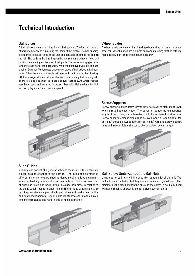
Ball GuidesA ball guide consists of a ball rail and a ball bushing. The ball rail is made
of hardened steel and runs along the inside of the profile. The ball bushing
is attached to the carriage of the unit and contains balls that roll against
the rail. The balls in the bushing can be recirculating or have fixed ball
positions depending on the type of ball guide. The recirculating type has a
longer life and better load capability while the fixed type typically is much
smaller. Danaher Motion uses three major types of ball guides in its linear
units. Either the compact single rail type with recirculating ball bushing
(A), the stronger double rail type also with recirculating ball bushings (B)
or the fixed ball position ball bushings type (not shown) which require
very little space and are used in the smallest units. Ball guides offer high
accuracy, high loads and medium speed.
Slide GuidesA slide guide consist of a guide attached to the inside of the profile and
a slide bushing attached to the carriage. The guide can be made of
different materials (e.g. polished hardened steel, anodized aluminium)
while the bushing is made of a polymer material. There are two types
of bushings, fixed and prism. Prism bushings can move in relation to the guide which results in longer life and higher load capabilities. Slide
bushings are silent, simple, reliable and robust and can be used in dirty
and dusty environments. They are also resistant to shock loads, have a
long life expectancy and require little or no maintenance.
Wheel GuidesA wheel guide consists of ball bearing wheels that run on a hardened
steel rail. Wheel guides are a simple and robust guiding method offering
high speeds, high loads and medium accuarcy.
Screw SupportsScrew supports allow screw driven units to travel at high speed even
when stroke becomes longer. The supports reduce the unsupported
length of the screw, that otherwise would be subjected to vibrations.
Screw supports come in single (one screw support on each side of the
carriage) or double (two supports on each side) versions. Screw support
units will have a slightly shorter stroke for a given overall length.
Ball Screw Units with Double Ball NutsUsing double ball nuts will increase the repeatability of the unit. The
ball nuts are installed so that they are pre-tensioned against each other
eleminating the play between the nuts and the screw. A double nut unitwill have a slightly shorter stroke for a given overall length.
A
B

7/23/2019 Linear Actuator Danaher Motion
http://slidepdf.com/reader/full/linear-actuator-danaher-motion 10/22410 www.danahermotion.com
Technical Introduction
Single CarriageSingle carriage units have one carriage. Some linear unit models also
have the option of long or short single carriage. The long carriage handle
higher loads but will have a longer overall length for a given stroke.
Cover BandCover bands are used on some units to protect then from the ingress of
foreign objects through the opening in the profile where the carriage
runs. They are made of plastic (A) or stainless steel (B). In the case of
plastic the cover band seals the profile by snapping into small grooves
running along the carriage opening. In the case of stainless steel the
cover band seal the profile magnetically using magnet strips mounted
on each side of the carriage opening. Some units equipped with cover
bands also have a self-adjusting cover band tensioning mechanism. This
eleminates any slack in the cover band that can occur from temperaure
changes, thus improving the sealing degree and the expected life of the
cover band.
Double CarriagesDouble carriage units have two carriages which gives them higher load
capabilites than single carriage units. When ordering a double carriage
unit the distance between the two carriages needs to be defined. This
distance is called LA or Lc depending on the model.
Theoretical Stroke and Practical StrokeThe theoretical maximum stroke (S max) is the length that the carriage
can travel from one end of the unit to the other. However, using the
maximum stroke means that the carriage will collide with the ends of
the profile. The practical stroke is therefore shorter. We recommend
that you specify a unit that have at least 100 mm longer stroke than the
maximum stroke you need so that the unit can stop before colliding with
the ends and also allow for some adjustment of the unit postition at the
mounting.
Units with Left/right Moving CarriagesUnits with left/right moving carriages have two carriages moving in
opposite directions when the drive shaft is rotated. This type of unit has
a ball screw where half of the screw has a left hand thread and the other
half a right hand thread.
A
B
7/23/2019 Linear Actuator Danaher Motion
http://slidepdf.com/reader/full/linear-actuator-danaher-motion 11/22411
Linear Units
www.danahermotion.com
Technical Introduction
MaintenanceMost units require lubrication. General lubrication requirements can be
found in the general specifications table on the product data pages. The
lubrication intervals, grease qualities and specific lubrication instructions
can be found in the installation and service manual of each unit. No
other regular maintenance is needed except for normal cleaning and
inspection. Units with a cover band may also require irregular cover band
replacement due to wear. The belt in belt driven units should not require
re-tensioning under normal operating conditions.
Mounting PositionMost units can be mounted in any direction. Any restrictions on mounting
positions are shown on the product presentation pages at the beginning
of each product category chapter. Even where units may be mounted inany direction there are some considerations. None of the units are self-
locking which means that a vertical unit will drop the carriage/load if no
external brake (such as a brake in the motor, etc.) is applied to the drive
shaft of the unit. In the case of belt driven units care must be taken as the
carriage/load will drop immediately in the case of a belt breakage. This is
particularly important in vertical applications. All ball screw driven units
are equipped with a safety nut to prevent the carriage/load being released
in case of ball breakage.
Working EnvironmentAll units are designed for use in normal industrial environments. Units
which have an open profile (i.e. have no cover band) are more sensitive to
dust, dirt and fluids. These units require some kind of cover if they are used
in environments where dust, dirt or fluids are present. Optional bellows/
shrouds are available for some of our open profile units. Enhanced wash-
down or chemical protection can be ordered for our closed profile units.
Please refer to the accessory pages. In all cases where a unit will be
exposed to aggressive chemicals, heavy vibrations or other potentially
harmful processes we recommend that you contact us for further advice.
Duty CycleAll units are designed for a 100% duty cycle. However, where the unit
runs at extreme load, speed, acceleration and temperature or for long
operating periods the expected life time may be reduced.
Operation and Storage TemperatureOperational temperature limits can be found in the performance tables
on the product data pages. Units can be stored or transported within the
same temperature range. Please contact us if the unit will be exposed
to higher/lower temperatures than recommended during storage or
transportation
Load and Load Torque ValuesFor some units the load and load torque values are given for both the com-
plete unit and the guiding system. The values for the complete unit are
the values under which the unit can operate. The values for the guiding
system should only be used when comparing different units and do not
describe the actual performance of the complete unit.
Deflection of the ProfileSome units require support along the whole profile whilst some are
self supporting over a specified span. Further details can be found on
the product data pages. The recommended support intervals should
be followed to minimise deflection of the unit. The maximum distance
between the support points is shown on the product data pages. The
deflection of the unit can also be calculated using the information in theAdditional data and calculations chapter.
Lifetime ExpectancyWhen determining the lifetime for a linear unit it is necessary to evaluate
all forces and moments that are acting on the unit. The data and formulas
given in this catalogue serve as a basis for this. For a more detailed lifetime
calculation please use our sizing and selection software. Please contact
us for further guidance.
End of Stroke Limit SwitchesIf a unit runs at speed to the ends of its stroke there is a risk of damage.
Damage can be prevented by using end of stroke limit switches to detect
and engage a brake and/or cut power to the motor when the unit nears the
end of the unit. You must ensure that there is sufficient distance between
the end of stroke limit switch and the end of the unit, to allow the carriage
to come to a complete stop before colliding with the end. The required
stopping distance depends on the speed and the load and will have to be
calculated for each application. The stopping distance must be taken into
account when defining the necessary stroke.
Position FeedbackThe position of the carriage/rod/lifting profile can be obtained in many
ways. The most common way is to equip the unit with an encoder or to
use a motor which has a built in feed back device (encoder, resolver, etc.).
To many units there are encoders or/and encoder mounting kits available.See the accessory chapter.
Packages and Multi Axis KitsDanaher Motion can offer complete pre-defined packages (linear unit,
gear and servo motor assembled and shipped with servo drive and ca-
bles) as well as mounting kits for the creation of two and three axis sys-
tems Please contact us for further information.
7/23/2019 Linear Actuator Danaher Motion
http://slidepdf.com/reader/full/linear-actuator-danaher-motion 12/22412 www.danahermotion.com

7/23/2019 Linear Actuator Danaher Motion
http://slidepdf.com/reader/full/linear-actuator-danaher-motion 13/22413
Linear Units
www.danahermotion.com
Linear Units with Ball Screw Drive and Ball Guide
PowerLine, ForceLine, Microstage, AccuSlide
Velocity
Acceleration
Repeatability
Force
Stiffness
Cost
Maintenance
Noise
Typical Applications
Typical applications are where high accuracy and load capability is required but
where speed is less important. Typical examples are machining operations and in
the handling of heavy goods that need accurate positioning.
Guide Robustness Load Torque

7/23/2019 Linear Actuator Danaher Motion
http://slidepdf.com/reader/full/linear-actuator-danaher-motion 14/22414 www.danahermotion.com
Parameter WM40S WM40D WM60D WM60S WM60X WM80D WM80S WM120D
Profile size (width × height) [mm] 40 × 40 40 × 40 60 × 60 60 × 60 60 × 60 80 × 80 80 × 80 120 × 120
Stroke length (S max), maximum [mm] 2000 2000 11000 5000 10340 11000 5000 11000
Linear speed, maximum [m/s] 0,25 0,25 2,5 2,5 0,25 2,5 2,5 2,0
Dynamic carriage load (Fz), maximum [N] 600 600 2000 1400 2000 3000 2100 6000
Remarks single ballnut
double ballnuts
double ballnuts
single ballnut
left/rightscrew
double ballnuts
single ballnut
double ballnuts
Page 16 18 20 22 24 26 28 30
Parameter WV60 WV80 WV120
Profile size (width × height) [mm] 60 × 60 80 × 80 120 × 120
Stroke length (S max), maximum [mm] 11000 11000 11000
Linear speed, maximum [m/s] 2,5 2,5 2,0
Dynamic carriage load (Fz), maximum [N] - - -
Remarks double ball nuts
the units has no guides
double ball nuts
the units has no guides
double ball nuts
the units has no guides
Page 32 34 36
Parameter MLSM60D MLSM80D
Profile size (width × height) [mm] 160 × 65 240 × 85
Stroke length (S max), maximum [mm] 5500 5200
Linear speed, maximum [m/s] 2,5 2,0
Dynamic carriage load (Fz), maximum [N] 6000 8000
Remarks double ball nuts double ball nuts
Page 38 40
Features
• Can be installed in all directions
• Patented guide system• Patented plastic cover band
• Patented screw support system
Features
• Can be installed in all directions
• Patented guide system
• Patented self-adjusting plastic cover band
• Patented screw support system
Features
• Can be installed in all directions
• Patented self-adjusting plastic cover band
• Patented screw support system
• The units require external guides
ForceLine MLSM
PowerLine WM
PowerLine WV
WM40
WV80
MLSM80D

7/23/2019 Linear Actuator Danaher Motion
http://slidepdf.com/reader/full/linear-actuator-danaher-motion 15/22415
Linear Units
www.danahermotion.com
Parameter 2HBE10 2HBE20
Profile size (width × height) [mm] 100 × 33,5 200 × 44
Stroke length (S max), maximum [mm] 850 2800
Linear speed, maximum [m/s] 0,5 1,3
Dynamic carriage load (Fz), maximum [N] 8250 38000
Remarks no cover band, bellows or shrouds option
available
no cover band, bellows or shrouds option
available
Page 42 44
Features
• Can be installed in all directions
• High load capablities
• Low profile height
• Play free ball screw offer high repeatability
AccuSlide 2HBE
2HBE20
WM-Series Technical Presentation
Screw supportPatented screw support system
permits high speed at long stroke
lengths while reducing the stroke
with a minimum.
Double ball nutsDouble pre-tensioned ball nuts
improve the accuracy and allows
re-tensioning increasing the
lifetime of the unit.
Central lubricationOne central lubrication point on
the carriage services the entire
unit resulting in a minimum
maintenace required.
Ball guidesIntegrated patented ball guides
with hardened steel tracks for
optimum performance.
Cover bandThe patented self-adjusting
cover band protect the unit from
the penetration of dirt, dust and
liquids.
Ball cagesThe balls in the ball guides are
protected by a ball cage which
ensures a long life.

7/23/2019 Linear Actuator Danaher Motion
http://slidepdf.com/reader/full/linear-actuator-danaher-motion 16/22416 www.danahermotion.com
WM40S
Ball Screw Drive, Ball Guide, Single Ball Nut
Performance Specifications
Parameter WM40S
Stroke length (S max), maximum [mm] 2000
Linear speed, maximum [m/s] 0,25
Acceleration, maximum [m/s2] 20
Repeatability [± mm] 0,02
Input speed, maximum [rpm] 3000
Operation temperature limits [°C] 0 – 80
Dynamic load (Fx), maximum [N] 1000
Dynamic load (Fy), maximum [N] 4501 / 53002
Dynamic load (Fz), maximum [N] 6001 / 67902
Dynamic load torque (Mx), maximum [Nm] 101 / 302
Dynamic load torque (My), maximum [Nm] 301 / 2302
Dynamic load torque (Mz), maximum [Nm] 301 / 2302
Drive shaft force (Frd), maximum [N] 100
Drive shaft torque (Mta), maximum [Nm] 3
Ball screw diameter (d0) [mm] 12
Ball screw lead (p) [mm] 5
Weight
of unit with zero stroke
of every 100 mm of stroke
of each carriage
[kg]
1,50
0,30
0,36
General Specifications
Parameter WM40S
Profile size (w × h) [mm] 40 × 40
Type of screw ball screw with single nut
Carriage sealing system self-adjusting plastic cover band
Screw supports included in all units that require
screw supports
Lubrication central lubrication of all parts that
require lubrication
Included accessories 4 × mounting clamps
Carriage Idle Torque (M idle) [Nm]
Input speed [rpm]Screw lead [mm]
p = 5
150 0,3
1500 0,5
3000 0,8
M idle = the input torque needed to move the carriage with no load on it.
» Ordering key - see page 202
» Accessories - see page 137
» Additional data - see page 191
1
Value for the complete unit2 Value for the ball guide only
Definition of Forces
Deflection of the Profile
A mounting clamp must be installed at least at every 750 mm to be able to operate the
maximum load. Less clamps may be required if less load is being operated, see the additional
technical data for more information.
Critical Speed

7/23/2019 Linear Actuator Danaher Motion
http://slidepdf.com/reader/full/linear-actuator-danaher-motion 17/22417
Linear Units
www.danahermotion.com
WM40S
Ball Screw Drive, Ball Guide, Single Ball Nut
Double Carriages
Parameter WM40S
Minimum distance between carriages (L A) [mm] 175
Dynamic load (Fy), maximum [N] 900
Dynamic load (Fz), maximum [N] 1200
Dynamic load torque (My), maximum [Nm] L A1 × 0,45
Dynamic load torque (Mz), maximum [Nm] L A 1 × 0,6
Force required to move second carriage [N] 40
Total length (L tot) [mm] S max + C + L A
A1: depth 7
A2: lubricating nipple on both sides DIN3405 D 1/A
Stroke length (S max) [mm] A [mm] B [mm] C [mm]
0 – 500 (0 – 450) 65 35 270 (320)
501 – 1100 (451 – 1050) 65 45 280 (330)
1101 – 2000 (1051 – 1950) 70 60 300 (350)
A3: socket cap screw ISO4762-M5×12 8.8
A4: ENF inductive sensor rail option kit (optional)
Values between brackets = for units with long carriage
1 Value in mm

7/23/2019 Linear Actuator Danaher Motion
http://slidepdf.com/reader/full/linear-actuator-danaher-motion 18/22418 www.danahermotion.com
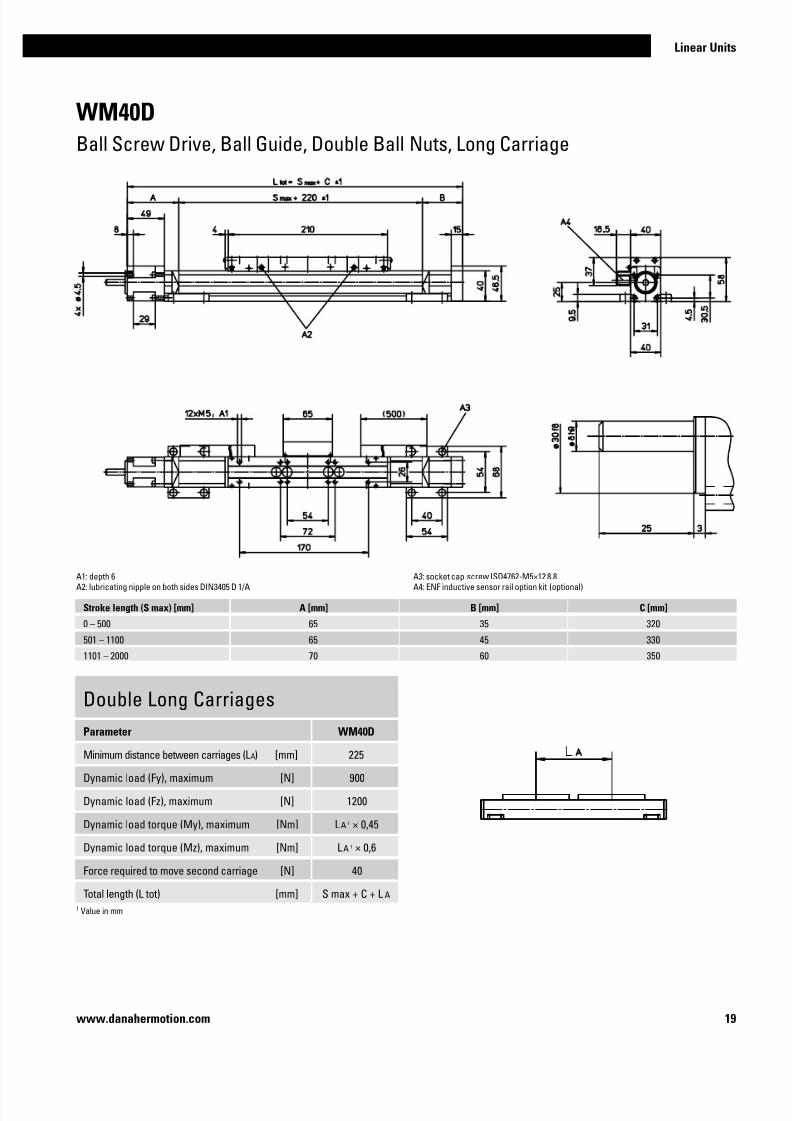
WM40D
Ball Screw Drive, Ball Guide, Double Ball Nuts, Long Carriage
Performance Specifications
Parameter WM40D
Stroke length (S max), maximum [mm] 1950
Linear speed, maximum [m/s] 0,25
Acceleration, maximum [m/s2] 20
Repeatability [± mm] 0,01
Input speed, maximum [rpm] 3000
Operation temperature limits [°C] 0 – 80
Dynamic load (Fx), maximum [N] 1000
Dynamic load (Fy), maximum [N] 4501 / 53002
Dynamic load (Fz), maximum [N] 6001 / 67902
Dynamic load torque (Mx), maximum [Nm] 101 / 302
Dynamic load torque (My), maximum [Nm] 301 / 2302
Dynamic load torque (Mz), maximum [Nm] 301 / 2302
Drive shaft force (Frd), maximum [N] 100
Drive shaft torque (Mta), maximum [Nm] 3
Ball screw diameter (d0) [mm] 12
Ball screw lead (p) [mm] 5
Weight
of unit with zero stroke
of every 100 mm of stroke of each carriage
[kg]
1,90
0,300,60
General Specifications
Parameter WM40D
Profile size (w × h) [mm] 40 × 40
Type of screw ball screw with double nuts
Carriage sealing system self-adjusting plastic cover band
Screw supports included in all units that require
screw supports
Lubrication central lubrication of all parts that
require lubrication
Included accessories 4 × mounting clamps
Carriage Idle Torque (M idle) [Nm]
Input speed [rpm]Screw lead [mm]
p = 5
150 0,4
1500 0,6
3000 0,9
M idle = the input torque needed to move the carriage with no load on it.
1
Value for the complete unit2 Value for the ball guide only
Definition of Forces
Deflection of the Profile
A mounting clamp must be installed at least at every 750 mm to be able to operate the
maximum load. Less clamps may be required if less load is being operated, see the additional
technical data for more information.
Critical Speed
» Ordering key - see page 202
» Accessories - see page 137
» Additional data - see page 191
7/23/2019 Linear Actuator Danaher Motion
http://slidepdf.com/reader/full/linear-actuator-danaher-motion 19/22419
Linear Units
www.danahermotion.com
WM40D
Ball Screw Drive, Ball Guide, Double Ball Nuts, Long Carriage
Double Long Carriages
Parameter WM40D
Minimum distance between carriages (L A) [mm] 225
Dynamic load (Fy), maximum [N] 900
Dynamic load (Fz), maximum [N] 1200
Dynamic load torque (My), maximum [Nm] L A 1 × 0,45
Dynamic load torque (Mz), maximum [Nm] L A 1 × 0,6
Force required to move second carriage [N] 40
Total length (L tot) [mm] S max + C + L A
A1: depth 6A2: lubricating nipple on both sides DIN3405 D 1/A
A3: socket cap screw ISO4762-M5×12 8.8A4: ENF inductive sensor rail option kit (optional)
Stroke length (S max) [mm] A [mm] B [mm] C [mm]
0 – 500 65 35 320
501 – 1100 65 45 330
1101 – 2000 70 60 350
1 Value in mm

7/23/2019 Linear Actuator Danaher Motion
http://slidepdf.com/reader/full/linear-actuator-danaher-motion 20/22420 www.danahermotion.com
WM60D
Ball Screw Drive, Ball Guide, Double Ball Nuts
Performance Specifications
Parameter WM60D
Stroke length (S max), maximum
screw lead 5, 20 mm
screw lead 50 mm
[mm]
11000
5000
Linear speed, maximum [m/s] 2,5
Acceleration, maximum [m/s2] 20
Repeatability [± mm] 0,01
Input speed, maximum [rpm] 3000
Operation temperature limits [°C] 0 – 80
Dynamic load (Fx), maximum [N] 4000
Dynamic load (Fy), maximum [N] 20001 / 459802
Dynamic load (Fz), maximum [N] 20001 / 423202
Dynamic load torque (Mx), maximum [Nm] 1001 / 7402
Dynamic load torque (My), maximum [Nm] 2001 / 29902
Dynamic load torque (Mz), maximum [Nm] 2001 / 32502
Drive shaft force (Frd), maximum [N] 500
Drive shaft torque (Mta), maximum [Nm] 35
Ball screw diameter (d0) [mm] 20
Ball screw lead (p) [mm] 5, 20, 50
Weight
of unit with zero stroke
of every 100 mm of stroke
of each carriage
[kg]
6,16
0,65
1,99
General Specifications
Parameter WM60D
Profile size (w × h) [mm] 60 × 60
Type of screw ball screw with double nut
Carriage sealing system self-adjusting plastic cover band
Screw supports included in all units that require
screw supports
Lubrication central lubrication of all parts that
require lubrication
Included accessories 4 × mounting clamps
Carriage Idle Torque (M idle) [Nm]
Input speed [rpm]Screw lead [mm]
p = 5 p = 20 p = 50
150 0,8 1,3 1,6
1500 1,4 2,0 2,4
3000 1,8 2,3 2,6
M idle = the input torque needed to move the carriage with no load on it.
1 Value for the complete unit2 Value for the ball guide only
Definition of Forces
Deflection of the Profile
A mounting clamp must be installed at least at every 750 mm to be able to operate the
maximum load. Less clamps may be required if less load is being operated, see the additional
technical data for more information. Units with a profile length over 6300 mm consists of twoprofiles where the joint between the two profiles must be addequately supported on both
sides.
» Ordering key - see page 202
» Accessories - see page 137
» Additional data - see page 191

7/23/2019 Linear Actuator Danaher Motion
http://slidepdf.com/reader/full/linear-actuator-danaher-motion 21/22421
Linear Units
www.danahermotion.com
WM60D
Ball Screw Drive, Ball Guide, Double Ball Nuts
Long Carriage
Parameter WM60D
Carriage length [mm] 450
Dynamic load torque (My), maximum [Nm] 500
Dynamic load torque (Mz), maximum [Nm] 500
Weight [kg] 3,1
Double Carriages
Parameter WM60D
Minimum distance between carriages (L A) [mm] 335
Dynamic load (Fy), maximum [N] 4000
Dynamic load (Fz), maximum [N] 4000
Dynamic load torque (My), maximum [Nm] L A 1 × 2
Dynamic load torque (Mz), maximum [Nm] L A 1 × 2
Force required to move second carriage [N] 200
Total length (L tot) [mm] S max + C + L A
A1: depth 11
A2: socket cap screw ISO4762-M6×20 8.8
A3: ENF inductive sensor rail option kit (optional)
A1: depth 11
A4: tapered lubricating nipple to DIN71412 AM6 on fixed-bearing side as standard feature
A5: can be changed over to one of the three alternative lubricating points by the customer
Stroke length (S max) [mm] A [mm] B [mm] C [mm]
0 - 695 (0 - 505) 115 65 460 (650)
696 - 1335 (506 - 1145) 165 115 560 (750)
1336 - 2075 (1146 - 1885) 185 135 600 (790)
2076 - 2780 (1886 - 2590) 210 160 650 (840)
Values between brackets = for units with long carriage
Stroke length (S max) [mm] A [mm] B [mm] C [mm]
2781 - 3545 (2591 - 3355) 230 180 690 (880)
3546 - 4285 (3366 - 4095) 250 200 730 (920)
4286 - 5015 (4096 - 4825) 275 225 780 (970)
5016 - 11000 (4826 - 10810) contact customer service
1 Value in mm

7/23/2019 Linear Actuator Danaher Motion
http://slidepdf.com/reader/full/linear-actuator-danaher-motion 22/22422 www.danahermotion.com
WM60S
Ball Screw Drive, Ball Guide, Single Ball Nut, Short Carriage
Performance Specifications
Parameter WM60S
Stroke length (S max), maximum [mm] 5000
Linear speed, maximum [m/s] 2,5
Acceleration, maximum [m/s2] 10
Repeatability [± mm] 0,02
Input speed, maximum [rpm] 3000
Operation temperature limits [°C] 0 – 80
Dynamic load (Fx), maximum [N] 2800
Dynamic load (Fy), maximum [N] 14001 / 259202
Dynamic load (Fz), maximum [N] 14001 / 238602
Dynamic load torque (Mx), maximum [Nm] 501 / 4102
Dynamic load torque (My), maximum [Nm] 1001 / 3202
Dynamic load torque (Mz), maximum [Nm] 1001 / 3202
Drive shaft force (Frd), maximum [N] 500
Drive shaft torque (Mta), maximum [Nm] 35
Ball screw diameter (d0) [mm] 20
Ball screw lead (p) [mm] 5, 20, 50
Weight
of unit with zero stroke of every 100 mm of stroke
of each carriage
[kg]
3,800,65
1,00
General Specifications
Parameter WM60S
Profile size (w × h) [mm] 60 × 60
Type of screw ball screw with single nut
Carriage sealing system self-adjusting plastic cover band
Screw supports included in all units that require
screw supports
Lubrication central lubrication of all parts that
require lubrication
Included accessories 4 × mounting clamps
Carriage Idle Torque (M idle) [Nm]
Input speed [rpm]Screw lead [mm]
p = 5 p = 20 p = 50
150 0,7 1,0 1,4
1500 1,1 1,6 2,0
3000 1,5 1,8 2,2
M idle = the input torque needed to move the carriage with no load on it.
1 Value for the complete unit2 Value for the ball guide only
Definition of Forces
Deflection of the Profile
A mounting clamp must be installed at least at every 750 mm to be able to operate the
maximum load. Less clamps may be required if less load is being operated, see the additional technical data for more information.
» Ordering key - see page 202
» Accessories - see page 137
» Additional data - see page 191

7/23/2019 Linear Actuator Danaher Motion
http://slidepdf.com/reader/full/linear-actuator-danaher-motion 23/22423
Linear Units
www.danahermotion.com
WM60S
Ball Screw Drive, Ball Guide, Single Ball Nut, Short Carriage
Stroke length (S max) [mm] A [mm] B [mm] C [mm]
0 - 580 95 20 335
581 - 1140 110 60 390
1141 - 1805 130 80 430
1806 - 2460 155 105 480
Stroke length (S max) [mm] A [mm] B [mm] C [mm]
2461 - 3125 175 125 520
3126 - 3780 200 150 570
3781 - 4445 220 170 610
4446 - 5000 240 190 650
Double Short Carriages
Parameter WM60SMinimum distance between carriages (L A) [mm] 255
Dynamic load (Fy), maximum [N] 2800
Dynamic load (Fz), maximum [N] 2800
Dynamic load torque (My), maximum [Nm] L A 1 × 1,4
Dynamic load torque (Mz), maximum [Nm] L A 1 × 1,4
Force required to move second carriage [N] 180
Total length (L tot) [mm] S max + C + L A
A1: depth 11A2: socket cap screw ISO4762-M6×20 8.8A3: ENF inductive sensor rail option kit (optional)
A4: tapered lubricating nipple to DIN71412 AM6 on fixed-bearing side as standard featureA5: can be changed over to one of the three alternative lubricating points by the customer
1 Value in mm

7/23/2019 Linear Actuator Danaher Motion
http://slidepdf.com/reader/full/linear-actuator-danaher-motion 24/22424 www.danahermotion.com
WM60X
Ball Screw Drive, Ball Guide, Left/right Moving Carriages
Performance Specifications
Parameter WM60X
Stroke length (S max), maximum [mm] 10340
Linear speed, maximum [m/s] 0,25
Acceleration, maximum [m/s2] 20
Repeatability [± mm] 0,01
Input speed, maximum [rpm] 3000
Operation temperature limits [°C] 0 – 80
Dynamic load (Fx), maximum [N] 4000
Dynamic load (Fy), maximum [N] 20001 / 459802
Dynamic load (Fz), maximum [N] 20001 / 423202
Dynamic load torque (Mx), maximum [Nm] 1001 / 7402
Dynamic load torque (My), maximum [Nm] 2001 / 29902
Dynamic load torque (Mz), maximum [Nm] 2001 / 32502
Drive shaft force (Frd), maximum [N] 500
Drive shaft torque (Mta), maximum [Nm] 35
Ball screw diameter (d0) [mm] 20
Ball screw lead (p) [mm] 5
Weight
of unit with zero stroke of every 100 mm of stroke
of each carriage
[kg]
10,33 0,65
1,99
General Specifications
Parameter WM60X
Profile size (w × h) [mm] 60 × 60
Type of screw ball screw with double nut
Carriage sealing system self-adjusting plastic cover band
Screw supports included in all units that require
screw supports
Lubrication central lubrication of all parts that
require lubrication
Included accessories 4 × mounting clamps
Carriage Idle Torque (M idle) [Nm]
Input speed [rpm]Screw lead [mm]
p = 5
150 1,6
1500 2,8
3000 3,6
M idle = the input torque needed to move the carriage with no load on it.
Definition of Forces
1 Value for the complete unit2 Value for the ball guide only
Deflection of the Profile
A mounting clamp must be installed at least at every 750 mm to be able to operate the
maximum load. Less clamps may be required if less load is being operated, see the additional
technical data for more information. Units with a profile length over 5400 mm consists of twoprofiles where the joint between the two profiles must be addequately supported on both
sides.
» Ordering key - see page 202
» Accessories - see page 137
» Additional data - see page 191

7/23/2019 Linear Actuator Danaher Motion
http://slidepdf.com/reader/full/linear-actuator-danaher-motion 25/22425
Linear Units
www.danahermotion.com
WM60X
Ball Screw Drive, Ball Guide, Left/right Moving Carriages
Stroke length (S max) [mm] A [mm] B [mm] C [mm] X [mm] Y [mm] Z [mm]
0 - 1390 (0 - 1200) 115 65 60 80 620 800
1391 - 2670 (1201 - 2480) 165 115 210 230 770 1050
2671 - 4150 (2481 - 3960) 185 135 250 270 810 1130
4151 - 5560 (3961 - 5370) 210 160 300 320 860 1230
5561 - 10340 (5371 - 10150) contact customer sevice
Long Carriage
Parameter WM60X
Carriage length [mm] 450
Dynamic load torque (My), maximum [Nm] 500
Dynamic load torque (Mz), maximum [Nm] 500
Weight [kg] 3,1
Values between brackets = for units with long carriage
A1: depth 11
A1: depth 11
A2: socket cap screw ISO4762-M6×20 8.8A3: ENF inductive sensor rail option kit (optional)
A4: tapered lubricating nipple to DIN71412 AM6 on fixed-bearing side as standard feature
A5: can be changed over to one of the three alternative lubricating points by the customer

7/23/2019 Linear Actuator Danaher Motion
http://slidepdf.com/reader/full/linear-actuator-danaher-motion 26/22426 www.danahermotion.com
WM80D
Ball Screw Drive, Ball Guide, Double Ball Nuts
Performance Specifications
Parameter WM80D
Stroke length (S max), maximum
screw lead 5, 10, 20 mm screw lead 50 mm
[mm]
11000 5000
Linear speed, maximum [m/s] 2,5
Acceleration, maximum [m/s2] 20
Repeatability [± mm] 0,01
Input speed, maximum [rpm] 3000
Operation temperature limits [°C] 0 – 80
Dynamic load (Fx), maximum [N] 5000
Dynamic load (Fy), maximum [N] 30001 / 574202
Dynamic load (Fz), maximum [N] 30001 / 549502
Dynamic load torque (Mx), maximum [Nm] 3501 / 13602
Dynamic load torque (My), maximum [Nm] 3001 / 42302
Dynamic load torque (Mz), maximum [Nm] 3001 / 42202
Drive shaft force (Frd), maximum [N] 700
Drive shaft torque (Mta), maximum [Nm] 55
Ball screw diameter (d0) [mm] 25
Ball screw lead (p) [mm] 5, 10, 20, 50
Weight
of unit with zero stroke of every 100 mm of stroke
of each carriage
[kg]
11,571,08
4,26
General Specifications
Parameter WM80D
Profile size (w × h) [mm] 80 × 80
Type of screw ball screw with double nuts
Carriage sealing system self-adjusting plastic cover band
Screw supports included in all units that require
screw supports
Lubrication central lubrication of all parts that
require lubrication
Included accessories 4 × mounting clamps
Carriage Idle Torque (M idle) [Nm]
Input speed [rpm]Screw lead [mm]
p = 5 p = 10 p = 20 p = 50
150 1,1 1,5 1,8 2,3
1500 1,7 2.1 2,3 3,0
3000 2,1 2,5 2,6 3,6
M idle = the input torque needed to move the carriage with no load on it.
1 Value for the complete unit2 Value for the ball guide only
Definition of Forces
Deflection of the Profile
A mounting clamp must be installed at least at every 750 mm to be able to operate the
maximum load. Less clamps may be required if less load is being operated, see the additional
technical data for more information. Units with a profile length over 6300 mm consists of twoprofiles where the joint between the two profiles must be addequately supported on both
sides.
» Ordering key - see page 202
» Accessories - see page 137
» Additional data - see page 191

7/23/2019 Linear Actuator Danaher Motion
http://slidepdf.com/reader/full/linear-actuator-danaher-motion 27/22427
Linear Units
www.danahermotion.com
WM80D
Ball Screw Drive, Ball Guide, Double Ball Nuts
Long Carriage
Parameter WM80D
Carriage length [mm] 450
Dynamic load torque (My), maximum [Nm] 750
Dynamic load torque (Mz), maximum [Nm] 750
Weight [kg] 6,4
Double Carriages
Parameter WM80D
Minimum distance between carriages (L A) [mm] 360
Dynamic load (Fy), maximum [N] 6000
Dynamic load (Fz), maximum [N] 6000
Dynamic load torque (My), maximum [Nm] L A 1 × 3
Dynamic load torque (Mz), maximum [Nm] L A 1 × 3
Force required to move second carriage [N] 250
Total length (L tot) [mm] S max + C + L A
A1: depth 12 mm
A2: socket cap screw ISO4762-M6×20 8.8A3: ENF inductive sensor rail option kit (optional)
A1: depth 12 mm
Stroke length (S max) [mm] A [mm] B [mm] C [mm]
0 - 780 (0 - 610) 120 80 500 (670)
781 - 1535 (611 - 1365) 170 125 595 (765)
1536 - 2375 (1366 - 2205) 190 145 635 (805)
2376 - 3205 (2206 - 3035) 215 170 685 (855)
A4: tapered lubricating nipple to DIN71412 AM6 on fixed-bearing side as standard feature
A5: can be changed over to one of three alternative lubrication points by customer
Values between brackets = for units with long carriage
Stroke length (S max) [mm] A [mm] B [mm] C [mm]
3206 - 4045 (3036 - 3875) 235 190 725 (895)
4046 - 4885 (3876 - 4715) 255 210 765 (935)
4886 - 5000 (4716 - 4830) 280 235 815 (985)
5001 - 11000 (4717 - 10830) contact customer service
1 Value in mm

7/23/2019 Linear Actuator Danaher Motion
http://slidepdf.com/reader/full/linear-actuator-danaher-motion 28/22428 www.danahermotion.com
WM80S
Ball Screw Drive, Ball Guide, Singel Ball Nut, Short Carriage
Performance Specifications
Parameter WM80S
Stroke length (S max), maximum [mm] 5000
Linear speed, maximum [m/s] 2,5
Acceleration, maximum [m/s2] 20
Repeatability [± mm] 0,02
Input speed, maximum [rpm] 3000
Operation temperature limits [°C] 0 – 80
Dynamic load (Fx), maximum [N] 3500
Dynamic load (Fy), maximum [N] 21001 / 374402
Dynamic load (Fz), maximum [N] 21001 / 358302
Dynamic load torque (Mx), maximum [Nm] 1501 / 8902
Dynamic load torque (My), maximum [Nm] 1801 / 5802
Dynamic load torque (Mz), maximum [Nm] 1801 / 6002
Drive shaft force (Frd), maximum [N] 700
Drive shaft torque (Mta), maximum [Nm] 55
Ball screw diameter (d0) [mm] 25
Ball screw lead (p) [mm] 5, 10, 20, 50
Weight
of unit with zero stroke of every 100 mm of stroke
of each carriage
[kg]
7,01,1
1,6
General Specifications
Parameter WM80S
Profile size (w × h) [mm] 80 × 80
Type of screw ball screw with single nut
Carriage sealing system self-adjusting plastic cover band
Screw supports included in all units that require
screw supports
Lubrication central lubrication of all parts that
require lubrication
Included accessories 4 × mounting clamps
Carriage Idle Torque (M idle) [Nm]
Input speed [rpm]Screw lead [mm]
p = 5 p = 10 p = 20 p = 50
150 0,9 1,1 1,3 2,0
1500 1,3 1,5 1,8 2,4
3000 1,7 1,8 2,0 2,9
M idle = the input torque needed to move the carriage with no load on it.
1 Value for the complete unit2 Value for the ball guide only
Definition of Forces
Deflection of the Profile
A mounting clamp must be installed at least at every 750 mm to be able to operate the
maximum load. Less clamps may be required if less load is being operated, see the additional technical data for more information.
» Ordering key - see page 202
» Accessories - see page 137
» Additional data - see page 191

7/23/2019 Linear Actuator Danaher Motion
http://slidepdf.com/reader/full/linear-actuator-danaher-motion 29/22429
Linear Units
www.danahermotion.com
WM80S
Ball Screw Drive, Ball Guide, Singel Ball Nut, Short Carriage
Stroke length (S max) [mm] A [mm] B [mm] C [mm]
0 - 680 95 35 350
681 - 1310 125 80 425
1311 - 2065 150 105 475
2066 - 2830 170 125 515
Stroke length (S max) [mm] A [mm] B [mm] C [mm]
2831 - 3590 195 150 565
3591 - 4355 215 170 605
4356 - 5000 235 190 645
Double Carriages
Parameter WM80S
Minimum distance between carriages (L A) [mm] 280
Dynamic load (Fy), maximum [N] 4200
Dynamic load (Fz), maximum [N] 4200
Dynamic load torque (My), maximum [Nm] L A 1 × 2,1
Dynamic load torque (Mz), maximum [Nm] L A 1 × 2,1
Force required to move second carriage [N] 225
Total length (L tot) [mm] S max + C + L A
A1: depth 12 mm
A2: socket cap screw ISO4762-M6×20 8.8A3: ENF inductive sensor rail option kit (optional)
A4: tapered lubricating nipple to DIN71412 AM6 on fixed-bearing side as standard feature
A5: can be changed over to one of three alternative lubrication points by customer
1 Value in mm

7/23/2019 Linear Actuator Danaher Motion
http://slidepdf.com/reader/full/linear-actuator-danaher-motion 30/22430 www.danahermotion.com
WM120D
Ball Screw Drive, Ball Guide, Double Ball Nuts
Performance Specifications
Parameter WM120D
Stroke length (S max), maximum
screw lead 5, 10, 20 mm
screw lead 40 mm
[mm]
11000
5000
Linear speed, maximum [m/s] 2,0
Acceleration, maximum [m/s2] 20
Repeatability [± mm] 0,01
Input speed, maximum [rpm] 3000
Operation temperature limits [°C] 0 – 80
Dynamic load (Fx), maximum
screw lead 5, 10, 20 mm screw lead 40 mm
[N]
12000 8000
Dynamic load (Fy), maximum [N] 60001 / 748902
Dynamic load (Fz), maximum [N] 60001 / 716702
Dynamic load torque (Mx), maximum [Nm] 5001 / 28902
Dynamic load torque (My), maximum [Nm] 6001 / 66602
Dynamic load torque (Mz), maximum [Nm] 6001 / 69602
Drive shaft force (Frd), maximum [N] 1000
Drive shaft torque (Mta), maximum [Nm] 80
Ball screw diameter (d0) [mm] 32
Ball screw lead (p) [mm] 5, 10, 20, 40
Weight
of unit with zero stroke of every 100 mm of stroke
of each carriage
[kg]
25,91 1,93
9,25
General Specifications
Parameter WM120D
Profile size (w × h) [mm] 120 × 120
Type of screw ball screw with double nuts
Carriage sealing system self-adjusting plastic cover band
Screw supports included in all units that require
screw supports
Lubrication central lubrication of all parts that
require lubrication
Included accessories 4 × mounting clamps
Carriage Idle Torque (M idle) [Nm]
Input speed [rpm]Screw lead [mm]
p = 5 p = 10 p = 20 p = 40
150 1,4 2,0 2,3 2,4
1500 2,5 3,0 3,3 3,8
3000 3,0 3,7 4,0 4,3
M idle = the input torque needed to move the carriage with no load on it.
1 Value for the complete unit2 Value for the ball guide only
Definition of Forces
Deflection of the Profile
A mounting clamp must be installed at least at every 750 mm to be able to operate the
maximum load. Less clamps may be required if less load is being operated, see the additional
technical data for more information. Units with a profile length over 5400 mm consists of twoprofiles where the joint between the two profiles must be addequately supported on both
sides.
» Ordering key - see page 202
» Accessories - see page 137
» Additional data - see page 191

7/23/2019 Linear Actuator Danaher Motion
http://slidepdf.com/reader/full/linear-actuator-danaher-motion 31/22431
Linear Units
www.danahermotion.com
WM120D
Ball Screw Drive, Ball Guide, Double Ball Nuts
Long Carriage
Parameter WM120D
Carriage length [mm] 500
Dynamic load torque (My), maximum [Nm] 1500
Dynamic load torque (Mz), maximum [Nm] 1500
Weight [kg] 14,2
Double Carriages
Parameter WM120D
Minimum distance between carriages (L A) [mm] 450
Dynamic load (Fy), maximum [N] 12000
Dynamic load (Fz), maximum [N] 12000
Dynamic load torque (My), maximum [Nm] L A 1 × 6
Dynamic load torque (Mz), maximum [Nm] L A 1 × 6
Force required to move second carriage [N] 300
Total length (L tot) [mm] S max + C + L A
A1: depth 22
A2: socket cap screw ISO4762-M8×20 8.8
A1: depth 22
Stroke length (S max) [mm] A [mm] B [mm] C [mm]
0 - 890 (0 - 710) 155 100 595 (775)
891 - 1695 (711 - 1515) 225 170 735 (815)
1696 - 2625 (1516 - 2445) 260 205 805 (985)
2626 - 3555 (2446 - 3375) 295 240 875 (1055)
A3: tapered lubricating nipple to DIN71412 M8×1 on fixed-bearing side as standard feature
A4: can be changed over to one of the three alternative lubricating points by the customer
Values between brackets = for units with long carriage
Stroke length (S max) [mm] A [mm] B [mm] C [mm]
3556 - 4485 (3376 - 4305) 330 275 945 (1125)
4486 - 5000 (4306 - 4820) 365 310 1015 (1195)
5001 - 11000 (4307 - 10820) contact customer service
1 Value in mm

7/23/2019 Linear Actuator Danaher Motion
http://slidepdf.com/reader/full/linear-actuator-danaher-motion 32/22432 www.danahermotion.com
WV60
Ball Screw Drive, No Guides
Performance Specifications
Parameter WV60
Stroke length (S max), maximum
screw lead 5, 20 mm
screw lead 50 mm
[mm]
11000
5000
Linear speed, maximum [m/s] 2,5
Acceleration, maximum [m/s2] 20
Repeatability [± mm] 0,01
Input speed, maximum [rpm] 3000
Operation temperature limits [°C] 0 – 80
Dynamic load (Fx), maximum [N] 4000
Dynamic load (Fy), maximum [N] 0
Dynamic load (Fz), maximum [N] 0
Dynamic load torque (Mx), maximum [Nm] 0
Dynamic load torque (My), maximum [Nm] 0
Dynamic load torque (Mz), maximum [Nm] 0
Drive shaft force (Frd), maximum [N] 500
Drive shaft torque (Mta), maximum [Nm] 35
Ball screw diameter (d0) [mm] 20
Ball screw lead (p) [mm] 5, 20, 50
Weight
of unit with zero stroke
of every 100 mm of stroke
of each carriage
[kg]
4,72
0,55
1,42
General Specifications
Parameter WV60
Profile size (w × h) [mm] 60 × 60
Type of screw ball screw with double nut
Carriage sealing system self-adjusting plastic cover band
Screw supports included in all units that require
screw supports
Lubrication central lubrication of all parts that
require lubrication
Included accessories 4 × mounting clamps
Carriage Idle Torque (M idle) [Nm]
Input speed [rpm]Screw lead [mm]
p = 5 p = 20 p = 50
150 0,7 0,9 1,1
1500 1,3 1,5 1,5
3000 1,7 1,9 2,1
M idle = the input torque needed to move the carriage with no load on it.
Definition of Forces
Deflection of the Profile
A mounting clamp must be installed at least at every 750 mm to be able to operate the
maximum load. Less clamps may be required if less load is being operated, see the additional
technical data for more information. Units with a profile length over 6300 mm consists of twoprofiles where the joint between the two profiles must be addequately supported on both
sides.
» Ordering key - see page 203
» Accessories - see page 137
» Additional data - see page 191

7/23/2019 Linear Actuator Danaher Motion
http://slidepdf.com/reader/full/linear-actuator-danaher-motion 33/22433
Linear Units
www.danahermotion.com
WV60
Ball Screw Drive, No Guides
Stroke length (S max) [mm] A [mm] B [mm] C [mm]
0 - 690 130 80 430
691 - 1415 155 105 480
1416 - 2155 175 125 520
2156 - 2885 200 150 570
Stroke length (S max) [mm] A [mm] B [mm] C [mm]
2886 - 3625 220 170 610
3626 - 4355 245 195 660
4256 - 5095 265 215 700
5096 - 11000 contact customer service
A1: depth 11A2: socket cap screw ISO4762-M6×20 8.8A3: ENF inductive sensor rail option kit (optional)
A4: tapered lubricating nipple to DIN71412 AM6 on fixed-bearing side as standard featureA5: can be changed over to one of the three alternative lubricating points by the customer

7/23/2019 Linear Actuator Danaher Motion
http://slidepdf.com/reader/full/linear-actuator-danaher-motion 34/22434 www.danahermotion.com
WV80
Ball Screw Drive, No Guides
Performance Specifications
Parameter WV80
Stroke length (S max), maximum
screw lead 5, 10, 20 mm screw lead 50 mm
[mm]
11000 5000
Linear speed, maximum [m/s] 2,5
Acceleration, maximum [m/s2] 20
Repeatability [± mm] 0,01
Input speed, maximum [rpm] 3000
Operation temperature limits [°C] 0 – 80
Dynamic load (Fx), maximum [N] 5000
Dynamic load (Fy), maximum [N] 0
Dynamic load (Fz), maximum [N] 0
Dynamic load torque (Mx), maximum [Nm] 0
Dynamic load torque (My), maximum [Nm] 0
Dynamic load torque (Mz), maximum [Nm] 0
Drive shaft force (Frd), maximum [N] 700
Drive shaft torque (Mta), maximum [Nm] 55
Ball screw diameter (d0) [mm] 25
Ball screw lead (p) [mm] 5, 10, 20, 50
Weight
of unit with zero stroke of every 100 mm of stroke
of each carriage
[kg]
7,950,99
2,25
General Specifications
Parameter WV80
Profile size (w × h) [mm] 80 × 80
Type of screw ball screw with double nuts
Carriage sealing system self-adjusting plastic cover band
Screw supports included in all units that require
screw supports
Lubrication central lubrication of all parts that
require lubrication
Included accessories 4 × mounting clamps
Carriage Idle Torque (M idle) [Nm]
Input speed [rpm]Screw lead [mm]
p = 5 p = 10 p = 20 p = 50
150 0,9 1,1 1,3 1,4
1500 1,6 1,9 2,1 2,3
3000 2,0 2,4 2,6 3,0
M idle = the input torque needed to move the carriage with no load on it.
Definition of Forces
Deflection of the Profile
A mounting clamp must be installed at least at every 750 mm to be able to operate the
maximum load. Less clamps may be required if less load is being operated, see the additional
technical data for more information. Units with a profile length over 6300 mm consists of twoprofiles where the joint between the two profiles must be addequately supported on both
sides.
» Ordering key - see page 203
» Accessories - see page 137
» Additional data - see page 191

7/23/2019 Linear Actuator Danaher Motion
http://slidepdf.com/reader/full/linear-actuator-danaher-motion 35/22435
Linear Units
www.danahermotion.com
WV80
Ball Screw Drive, No Guides
Stroke length (S max) [mm] A [mm] B [mm] C [mm]
0 - 775 125 50 395
776 - 1670 145 95 460
1671 - 2505 170 115 505
2506 - 3340 190 140 550
Stroke length (S max) [mm] A [mm] B [mm] C [mm]
3341 - 4175 210 160 590
4176 - 5015 235 180 635
5016 - 11000 contact customer service
A1: depth 12 mm
A2: socket cap screw ISO4762-M6×20 8.8A3: ENF inductive sensor rail option kit (optional)
A4: tapered lubricating nipple to DIN71412 AM6 on fixed-bearing side as standard feature
A5: can be changed over to one of three alternative lubrication points by customer

7/23/2019 Linear Actuator Danaher Motion
http://slidepdf.com/reader/full/linear-actuator-danaher-motion 36/22436 www.danahermotion.com
WV120
Ball Screw Drive, No Guides
Performance Specifications
Parameter WV120
Stroke length (S max), maximum
screw lead 5, 10, 20 mm screw lead 40 mm
[mm]
11000 5000
Linear speed, maximum [m/s] 2,0
Acceleration, maximum [m/s2] 20
Repeatability [± mm] 0,01
Input speed, maximum [rpm] 3000
Operation temperature limits [°C] 0 – 80
Dynamic load (Fx), maximum
screw lead 5, 10, 20 mm
screw lead 40 mm
[N]
12000
8000
Dynamic load (Fy), maximum [N] 0
Dynamic load (Fz), maximum [N] 0
Dynamic load torque (Mx), maximum [Nm] 0
Dynamic load torque (My), maximum [Nm] 0
Dynamic load torque (Mz), maximum [Nm] 0
Drive shaft force (Frd), maximum [N] 1000
Drive shaft torque (Mta), maximum [Nm] 80
Ball screw diameter (d0) [mm] 32
Ball screw lead (p) [mm] 5, 10, 20, 40
Weight
of unit with zero stroke of every 100 mm of stroke
of each carriage
[kg]
18,10 1,94
4,75
General Specifications
Parameter WV120
Profile size (w × h) [mm] 120 × 120
Type of screw ball screw with double nuts
Carriage sealing system self-adjusting plastic cover band
Screw supports included in all units that require
screw supports
Lubrication central lubrication of all parts that
require lubrication
Included accessories 4 × mounting clamps
Carriage Idle Torque (M idle) [Nm]
Input speed [rpm]Screw lead [mm]
p = 5 p = 10 p = 20 p = 40
150 1,0 1,1 1,4 1,5
1500 2,1 2,2 2,5 2,8
3000 2,4 2,6 3,0 3,5
M idle = the input torque needed to move the carriage with no load on it.
Definition of Forces
Deflection of the Profile
A mounting clamp must be installed at least at every 750 mm to be able to operate the
maximum load. Less clamps may be required if less load is being operated, see the additional
technical data for more information. Units with a profile length over 5400 mm consists of twoprofiles where the joint between the two profiles must be addequately supported on both
sides.
» Ordering key - see page 203
» Accessories - see page 137
» Additional data - see page 191

7/23/2019 Linear Actuator Danaher Motion
http://slidepdf.com/reader/full/linear-actuator-danaher-motion 37/22437
Linear Units
www.danahermotion.com
WV120
Ball Screw Drive, No Guides
Stroke length (S max) [mm] A [mm] B [mm] C [mm]
0 - 940 145 50 465
941 - 1860 180 120 570
1861 - 2790 215 155 640
2791 - 3720 250 190 710
Stroke length (S max) [mm] A [mm] B [mm] C [mm]
3721 - 4650 285 225 780
4651 - 5000 320 255 845
5001 - 11000 contact customer service
A1: depth 22A2: socket cap screw ISO4762-M8×20 8.8
A3: tapered lubricating nipple to DIN71412 M8×1 on fixed-bearing side as standard featureA4: can be changed over to one of the three alternative lubricating points by the customer

7/23/2019 Linear Actuator Danaher Motion
http://slidepdf.com/reader/full/linear-actuator-danaher-motion 38/22438 www.danahermotion.com
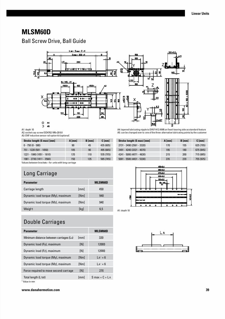
MLSM60D
Ball Screw Drive, Ball Guide
Performance Specifications
Parameter MLSM60D
Stroke length (S max), maximum [mm] 5500
Linear speed, maximum [m/s] 2,5
Acceleration, maximum [m/s2] 20
Repeatability [± mm] 0,01
Input speed, maximum [rpm] 3000
Operation temperature limits [°C] 0 – 80
Dynamic load (Fx), maximum [N] 5000
Dynamic load (Fy), maximum [N] 60001 / 550902
Dynamic load (Fz), maximum [N] 60001 / 550902
Dynamic load torque (Mx), maximum [Nm] 4001 / 28902
Dynamic load torque (My), maximum [Nm] 4601 / 44902
Dynamic load torque (Mz), maximum [Nm] 4601 / 44902
Drive shaft force (Frd), maximum [N] 350
Drive shaft torque (Mta), maximum [Nm] 60
Ball screw diameter (d0) [mm] 25
Ball screw lead (p) [mm] 5, 10, 20, 50
Weight
of unit with zero stroke of every 100 mm of stroke
of each carriage
[kg]
14,40 1,65
5,70
General Specifications
Parameter MLSM60D
Profile size (w × h) [mm] 160 × 65
Type of screw ball screw with double nuts
Carriage sealing system plastic cover band
Screw supports included in all units that require
screw supports
Lubrication central lubrication of all parts that
require lubrication
Included accessories 4 × mounting clamps
Carriage Idle Torque (M idle) [Nm]
Input speed [rpm]Screw lead [mm]
p = 5 p = 10 p = 20 p = 50
150 1,0 1,6 1,9 2,7
1500 1,6 2,2 2,3 3,4
3000 2,0 2,6 2,6 4,0
M idle = the input torque needed to move the carriage with no load on it.
1 Value for the complete unit2 Value for the ball guide only
Definition of Forces
Deflection of the Profile
A mounting clamp must be installed at least at every 750 mm to be able to operate the
maximum load. Less clamps may be required if less load is being operated, see the additional
technical data for more information.
» Ordering key - see page 204
» Accessories - see page 137
» Additional data - see page 191
7/23/2019 Linear Actuator Danaher Motion
http://slidepdf.com/reader/full/linear-actuator-danaher-motion 39/22439
Linear Units
www.danahermotion.com
MLSM60D
Ball Screw Drive, Ball Guide
Long Carriage
Parameter MLSM60D
Carriage length [mm] 450
Dynamic load torque (My), maximum [Nm] 940
Dynamic load torque (Mz), maximum [Nm] 940
Weight [kg] 6,5
Double Carriages
Parameter MLSM60D
Minimum distance between carriages (L A) [mm] 320
Dynamic load (Fy), maximum [N] 12000
Dynamic load (Fz), maximum [N] 12000
Dynamic load torque (My), maximum [Nm] L A 1 × 6
Dynamic load torque (Mz), maximum [Nm] L A 1 × 6
Force required to move second carriage [N] 270
Total length (L tot) [mm] S max + C + L A
A1: depth 10A2: socket cap screw ISO4762-M6×20 8.8
A3: ENF inductive sensor rail option kit (optional)
A1: depth 10
Stroke length (S max) [mm] A [mm] B [mm] C [mm]
0 - 750 (0 - 580) 90 45 435 (605)
751 - 1220 (581 - 1050) 105 90 495 (665)
1221 - 1980 (1051 - 1810) 125 110 535 (705)
1981 - 2730 (1811 - 2560) 150 135 585 (765)
A4: tapered lubricating nipple to DIN71412 AM6 on fixed-bearing side as standard featureA5: can be changed over to one of the three alternative lubricating points by the customer
Values between brackets = for units with long carriage
Stroke length (S max) [mm] A [mm] B [mm] C [mm]
2731 - 3490 (2561 - 3320) 170 155 625 (795)
3491 - 4240 (3321 - 4070) 195 180 675 (845)
4241 - 5000 (4071 - 4830) 215 200 715 (885)
5001 - 5500 (4831 - 5330) 235 220 755 (925)
1 Value in mm

7/23/2019 Linear Actuator Danaher Motion
http://slidepdf.com/reader/full/linear-actuator-danaher-motion 40/22440 www.danahermotion.com
MLSM80D
Ball Screw Drive, Ball Guide
Performance Specifications
Parameter MLSM80D
Stroke length (S max), maximum [mm] 5200
Linear speed, maximum [m/s] 2,0
Acceleration, maximum [m/s2] 20
Repeatability [± mm] 0,01
Input speed, maximum [rpm] 3000
Operation temperature limits [°C] 0 – 80
Dynamic load (Fx), maximum
screw lead 5, 10, 20 mm
screw lead 40 mm
[N]
12000
8000
Dynamic load (Fy), maximum [N] 80001 / 718602
Dynamic load (Fz), maximum [N] 80001 / 718602
Dynamic load torque (Mx), maximum [Nm] 7801 / 58902
Dynamic load torque (My), maximum [Nm] 9001 / 66402
Dynamic load torque (Mz), maximum [Nm] 9001 / 66402
Drive shaft force (Frd), maximum [N] 700
Drive shaft torque (Mta), maximum [Nm] 85
Ball screw diameter (d0) [mm] 32
Ball screw lead (p) [mm] 5, 10, 20, 40
Weight
of unit with zero stroke of every 100 mm of stroke
of each carriage
[kg]
29,5 2,7
11,5
General Specifications
Parameter MLSM80D
Profile size (w × h) [mm] 240 × 85
Type of screw ball screw with double nuts
Carriage sealing system plastic cover band
Screw supports included in all units that require
screw supports
Lubrication central lubrication of all parts that
require lubrication
Included accessories 4 × mounting clamps
Carriage Idle Torque (M idle) [Nm]
Input speed [rpm]Screw lead [mm]
p = 5 p = 10 p = 20 p = 40
150 1,6 2,2 2,5 2,8
1500 2,7 3,2 3,4 4,0
3000 3,2 4,0 4,2 4,5
M idle = the input torque needed to move the carriage with no load on it.
1 Value for the complete unit2 Value for the ball guide only
Definition of Forces
Deflection of the Profile
A mounting clamp must be installed at least at every 750 mm to be able to operate the
maximum load. Less clamps may be required if less load is being operated, see the additional
technical data for more information.
» Ordering key - see page 204
» Accessories - see page 137
» Additional data - see page 191

7/23/2019 Linear Actuator Danaher Motion
http://slidepdf.com/reader/full/linear-actuator-danaher-motion 41/22441
Linear Units
www.danahermotion.com
MLSM80D
Ball Screw Drive, Ball Guide
Long Carriage
Parameter MLSM80D
Carriage length [mm] 500
Dynamic load torque (My), maximum [Nm] 1750
Dynamic load torque (Mz), maximum [Nm] 1750
Weight [kg] 16
Double Carriages
Parameter MLSM80D
Minimum distance between carriages (L A) [mm] 400
Dynamic load (Fy), maximum [N] 16000
Dynamic load (Fz), maximum [N] 16000
Dynamic load torque (My), maximum [Nm] L A 1 × 8
Dynamic load torque (Mz), maximum [Nm] L A 1 ×8
Force required to move second carriage [N] 350
Total length (L tot) [mm] S max + C + L A
A1: depth 15A2: socket cap screw ISO4762-M8×20 8.8
A3: ENF inductive sensor rail option kit (optional)
A1: depth 15
Stroke length (S max) [mm] A [mm] B [mm] C [mm]
0 - 750 (0 - 570) 100 90 530 (710)
751 - 1140 (571 - 960) 130 120 590 (770)
1141 - 1880 (961 - 1700) 160 150 650 (830)
1881 - 2620 (1701 - 2440) 190 180 710 (890)
A4: tapered lubricating nipple to DIN71412 M8×1 on fixed-bearing side as standard featureA5: can be changed over to one of the three alternative lubricating points by the customer
Values between brackets = for units with long carriage
Stroke length (S max) [mm] A [mm] B [mm] C [mm]
2621 - 3360 (2441 - 3180) 220 210 770 (950)
3361 - 4100 (3181 - 3920) 250 240 830 (1010)
4101 - 4840 (3921 - 4660) 280 270 890 (1070)
4841 - 5000 (4661 - 4820) 310 300 950 (1130)
1 Value in mm

7/23/2019 Linear Actuator Danaher Motion
http://slidepdf.com/reader/full/linear-actuator-danaher-motion 42/22442 www.danahermotion.com
General Specifications
Parameter 2HBE10
Profile size (w × h) [mm] 100 × 33,5
Type of screw ball screw with double nut
Carriage sealing system none
Screw supportsnone
Lubrication lubrication of
screw and guides
Included accessories none Deflection of the Profile
2HBE10
Ball Screw Drive, Ball Guide
Performance Specifications
Parameter 2HBE10
Stroke length (S max), maximum [mm] 850
Linear speed, maximum [m/s] 0,5
Acceleration, maximum [m/s2] 20
Repeatability [± mm] 0,005
Input speed, maximum [rpm] 3000
Operation temperature limits [°C] -20 – 70
Dynamic load (Fx), maximum [N] 2500
Dynamic load (Fy), maximum [N] 20651 / 82502
Dynamic load (Fz), maximum [N] 20651 / 82502
Dynamic load torque (Mx), maximum [Nm] 2901 / 3952
Dynamic load torque (My), maximum [Nm] 2251 / 3052
Dynamic load torque (Mz), maximum [Nm] 2251 / 3052
Drive shaft force (Frd), maximum [N] 0
Drive shaft torque (Mta), maximum [Nm] 4,4
Ball screw diameter (d0) [mm] 16
Ball screw lead (p) [mm] 5, 10
Weight
of unit with zero stroke of every 100 mm of stroke
of each carriage
[kg]
2,590,69
0,82
1 Value for the complete unit2 Value for the ball guide only
Definition of Forces
The unit must be continiously supported by a machined surface under its entire length.
» Ordering key - see page 205
» Accessories - see page 137
» Additional data - see page 191
Carriage Idle Torque (M idle) [Nm]
Input speed [rpm]Screw lead [mm]
p = 5 p = 10
150 0,1 0,1
1500 0,1 0,1
3000 0,1 0,1
M idle = the input torque needed to move the carriage with no load on it.
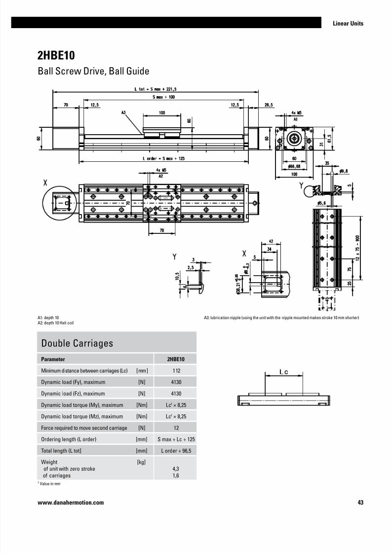
7/23/2019 Linear Actuator Danaher Motion
http://slidepdf.com/reader/full/linear-actuator-danaher-motion 43/22443
Linear Units
www.danahermotion.com
A1: depth 10A2: depth 10 Heli coil
A3: lubrication nipple (using the unit with the nipple mounted makes stroke 10 mm shorter)
2HBE10
Ball Screw Drive, Ball Guide
Double Carriages
Parameter 2HBE10
Minimum distance between carriages (Lc) [mm] 112
Dynamic load (Fy), maximum [N] 4130
Dynamic load (Fz), maximum [N] 4130
Dynamic load torque (My), maximum [Nm] Lc1 × 8,25
Dynamic load torque (Mz), maximum [Nm] Lc1 × 8,25
Force required to move second carriage [N] 12
Ordering length (L order) [mm] S max + Lc + 125
Total length (L tot] [mm] L order + 96,5
Weight of unit with zero stroke
of carriages
[kg]4,3
1,61 Value in mm

7/23/2019 Linear Actuator Danaher Motion
http://slidepdf.com/reader/full/linear-actuator-danaher-motion 44/22444 www.danahermotion.com
General Specifications
Parameter 2HBE20
Profile size (w × h) [mm] 200 × 44
Type of screw ball screw with double nut
Carriage sealing system none
Screw supportsnone
Lubrication lubrication of
screw and guides
Included accessories none
2HBE20
Ball Screw Drive, Ball Guide
Performance Specifications
Parameter 2HBE20
Stroke length (S max), maximum [mm] 2800
Linear speed, maximum [m/s] 1,3
Acceleration, maximum [m/s2] 20
Repeatability [± mm] 0,005
Input speed, maximum [rpm] 3000
Operation temperature limits [°C] -20 – 70
Dynamic load (Fx), maximum [N] 5000
Dynamic load (Fy), maximum [N] 95151 / 380002
Dynamic load (Fz), maximum [N] 95151 / 380002
Dynamic load torque (Mx), maximum [Nm] 27601 / 37702
Dynamic load torque (My), maximum [Nm] 21301 / 29102
Dynamic load torque (Mz), maximum [Nm] 21301 / 29102
Drive shaft force (Frd), maximum [N] 0
Drive shaft torque (Mta), maximum [Nm] 22
Ball screw diameter (d0) [mm] 25
Ball screw lead (p) [mm] 5, 10, 25
Weight
of unit with zero stroke of every 100 mm of stroke
of each carriage
[kg]
13,321,70
4,47
1 Value for the complete unit2 Value for the ball guide only
Deflection of the Profile
Definition of Forces
The unit must be continiously supported by a machined surface under its entire length.
» Ordering key - see page 205
» Accessories - see page 137
» Additional data - see page 191
Carriage Idle Torque (M idle) [Nm]
Input speed [rpm]Screw lead [mm]
p = 5 p = 10 p = 25
150 0,15 0,20 0,35
1500 0,16 0,21 0,38
3000 0,17 0,25 0,47
M idle = the input torque needed to move the carriage with no load on it.

7/23/2019 Linear Actuator Danaher Motion
http://slidepdf.com/reader/full/linear-actuator-danaher-motion 45/22445
Linear Units
www.danahermotion.com
2HBE20
Ball Screw Drive, Ball Guide
A1: depth 12A2: depth 15 Heli coil
A3: lubrication nipple (using the unit with the nipple mounted makes stroke 10 mm shorter)
Double Carriages
Parameter 2HBE20
Minimum distance between carriages (Lc) [mm] 210
Dynamic load (Fy), maximum [N] 19030
Dynamic load (Fz), maximum [N] 19030
Dynamic load torque (My), maximum [Nm] Lc1 × 38
Dynamic load torque (Mz), maximum [Nm] Lc1 × 38
Force required to move second carriage [N] 17
Ordering length (L order) [mm] S max + Lc + 240
Total length (L tot] [mm] L order + 145
Weight of unit with zero stroke
of carriages
[kg]21,5
9,01 Value in mm

7/23/2019 Linear Actuator Danaher Motion
http://slidepdf.com/reader/full/linear-actuator-danaher-motion 46/22446 www.danahermotion.com

7/23/2019 Linear Actuator Danaher Motion
http://slidepdf.com/reader/full/linear-actuator-danaher-motion 47/22447
Linear Units
www.danahermotion.com
Linear Units with Ball Screw Drive and Slide Guide
BaseLine, Movopart
Typical Applications
Typical applications are where low to medium loads needs to be moved at low to
medium speed. These units are also suited for harsh environments. Typical examples
are all types of machines in the food, chemical, paper and wood working industry.Materials handling is another area where these units are ideal.
Velocity
Acceleration
Repeatability
Force
Stiffness
Cost
Maintenance
Noise
Guide Robustness Load Torque

7/23/2019 Linear Actuator Danaher Motion
http://slidepdf.com/reader/full/linear-actuator-danaher-motion 48/22448 www.danahermotion.com
Parameter WB40 WB60
Profile size (width × height) [mm] 40 × 37 60 × 59
Stroke length (S max), maximum [mm] 1000 5200
Linear speed, maximum [m/s] 0,25 1,0
Dynamic carriage load (Fz), maximum [N] 250 650
Remarks Ball screw or lead screw drive Ball screw or lead screw drive
Page 50 52
Parameter M55 M75 M100
Profile size (width × height) [mm] 58 × 55 86 × 75 108 × 100
Stroke length (S max), maximum [mm] 3000 4000 6000
Linear speed, maximum [m/s] 1,0 1,6 1,6
Dynamic carriage load (Fz), maximum [N] 400 1485 3005
Remarks single ball nut or
composite nut
single ball nut or
composite nut
single ball nut or
composite nut
Page 54 56 58
Features
• Can be installed in all directions
• Self-adjusting stainless steel cover band
• Patented internal self-adjusting prism slide guides
• Wash down protected versions available
Features
• Can be installed in all directions
• Plastic cover band
• Robust external slide guides
• Ball screw or lead screw drive
BaseLine WB
Movopart M
WB40
M75

7/23/2019 Linear Actuator Danaher Motion
http://slidepdf.com/reader/full/linear-actuator-danaher-motion 49/22449
Linear Units
www.danahermotion.com
Parameter M75D M100D
Profile size (width × height) [mm] 86 × 75 108 × 100
Stroke length (S max), maximum [mm] 3550 6000
Linear speed, maximum [m/s] 1,6 1,6
Dynamic carriage load (Fz), maximum [N] 1485 3005
Remarks double ball nuts double ball nuts
Page 60 62
Features
• Can be installed in all directions
• Self-adjusting stainless steel cover band
• Patented intenal self-adjusting prism slide guides
• Wash down protected versions available
Movopart MD
M100D
WB-Series Technical Presentation
Cover bandThe durable plastic cover band
protect the interior of the unit
from the penetration of dirt, dust
and liquids.
Central lubricationOne central lubrication point on
the carriage services the entire
unit resulting in a minimum
maintenace required.
Slide guidesThe robust and accurate slide
guides can be easily replaced
by the user whenever needed.
Screw supportThe screw support system reduce
noise and vibrations and permits
high speed at long stroke lengths.
DriveSelect between the fast high
precision ball screw or the robust
lead screw with composite nut.

7/23/2019 Linear Actuator Danaher Motion
http://slidepdf.com/reader/full/linear-actuator-danaher-motion 50/22450 www.danahermotion.com
WB40
Ball Screw or Lead Screw Drive, Slide Guide
Performance Specifications
Parameter WB40
Stroke length (S max), maximum [mm] 1000
Linear speed, maximum [m/s] 0,25
Acceleration, maximum [m/s2] 5
Repeatability [± mm] 0,05
Input speed, maximum
Ball screw units
Lead screw units with composite nut
[rpm]
3000
1500
Operation temperature limits [°C] 0 – 80
Dynamic load (Fx), maximum
ball screw units / lead screw units
[N]
200 / 500
Dynamic load (Fy), maximum [N] 2001
Dynamic load (Fz), maximum [N] 2501
Dynamic load torque (Mx), maximum [Nm] 61
Dynamic load torque (My), maximum [Nm] 151
Dynamic load torque (Mz), maximum [Nm] 101
Drive shaft force (Frd), maximum [N] 80
Drive shaft torque (Mta), maximum [Nm] 1
Screw diameter (d0) [mm] 12
Screw lead (p)
ball screw units / lead screw units
[mm]
5 / 4, 8
Weight
of unit with zero stroke
of every 100 mm of stroke of each carriage
[kg]
1,07
0,300,45
General Specifications
Parameter WB40
Profile size (w × h) [mm] 40 × 37
Type of screw ball or lead screw with single nut
Carriage sealing system plastic cover band
Screw supports none
Lubrication central lubrication of all parts that
require lubrication
Included accessories 4 × mounting clamps
Carriage Idle Torque (M idle) [Nm]
Input speed [rpm]Screw lead [mm]
p = 4 p = 5 p = 8
150 - 0,02 -
1500 - 0,35 -
3000 - 0,50 -
M idle = the input torque needed to move the carriage with no load on it.
Definition of Forces
Critical Speed
Deflection of the Profile
1: For lead screw units
2: For ball screw units
A mounting clamp must be installed at least at every 750 mm to be able to operate the
maximum load. Less clamps may be required if less load is being operated, see the additional technical data for more information.
1 Value for the complete unit
» Ordering key - see page 206
» Accessories - see page 137
» Additional data - see page 192

7/23/2019 Linear Actuator Danaher Motion
http://slidepdf.com/reader/full/linear-actuator-danaher-motion 51/22451
Linear Units
www.danahermotion.com
WB40
Ball Screw or Lead Screw Drive, Slide Guide
A1: depth 10A2: lubricating nipple DIN3405 D 1/A
A3: socket cap screw ISO4762-M5×20 8.8A4: ENF inductive sensor rail option kit (optional)

7/23/2019 Linear Actuator Danaher Motion
http://slidepdf.com/reader/full/linear-actuator-danaher-motion 52/22452 www.danahermotion.com
WB60
Ball Screw or Lead Screw Drive, Slide Guide
Performance Specifications
Parameter WB60
Stroke length (S max), maximum [mm] 5200
Linear speed, maximum [m/s] 1,0
Acceleration, maximum [m/s2] 5
Repeatability [± mm] 0,05
Input speed, maximum
Ball screw units
Lead screw units with composite nut
[rpm]
3000
1500
Operation temperature limits [°C] 0 – 80
Dynamic load (Fx), maximum
ball screw units / lead screw units
[N]
2500 / 2500
Dynamic load (Fy), maximum [N] 5001
Dynamic load (Fz), maximum [N] 6501
Dynamic load torque (Mx), maximum [Nm] 301
Dynamic load torque (My), maximum [Nm] 701
Dynamic load torque (Mz), maximum [Nm] 501
Drive shaft force (Frd), maximum [N] 150
Drive shaft torque (Mta), maximum [Nm] 17
Screw diameter (d0) [mm] 20
Screw lead (p)
ball screw units / lead screw units
[mm]
5, 20 / 8
Weight
of unit with zero stroke
of every 100 mm of stroke of each carriage
[kg]
3,63
0,721,17
General Specifications
Parameter WB60
Profile size (w × h) [mm] 60 × 59
Type of screw ball or lead screw with single nut
Carriage sealing system plastic cover band
Screw supports number of screw supports to be
specified by customer at order
Lubrication central lubrication of all parts that
require lubrication
Included accessories 4 × mounting clamps
Carriage Idle Torque (M idle) [Nm]
Input speed [rpm]Screw lead [mm]
p = 5 p = 8 p = 20
150 0,5 - 0,7
1500 1,0 - 1,35
3000 1,5 - 1,8
M idle = the input torque needed to move the carriage with no load on it.
Definition of Forces
Critical Speed
Deflection of the Profile
1: Max. input speed for ball screw units
2: Max. input speed for lead screw units
3: No screw supports required
A mounting clamp must be installed at least at every 750 mm to be able to operate the
maximum load. Less clamps may be required if less load is being operated, see the additional technical data for more information.
1 Value for the complete unit
» Ordering key - see page 206
» Accessories - see page 137
» Additional data - see page 192
4: One pair of screw supports required
5: Two pairs of screw supports required
6: Three pairs of screw supports required

7/23/2019 Linear Actuator Danaher Motion
http://slidepdf.com/reader/full/linear-actuator-danaher-motion 53/22453
Linear Units
www.danahermotion.com
WB60
Ball Screw or Lead Screw Drive, Slide Guide
A1: depth 12A2: lubricating nipple DIN3405 D 1/A
A3: socket cap screw ISO4762-M6×20 8.8
A4: depth 10A5: ENF inductive sensor rail option kit (optional)

7/23/2019 Linear Actuator Danaher Motion
http://slidepdf.com/reader/full/linear-actuator-danaher-motion 54/22454 www.danahermotion.com
Deflection of the Profile
M55
Ball Screw Drive, Slide Guide
Performance Specifications
Parameter M55
Stroke length (S max), maximum [mm] 3000
Linear speed, maximum [m/s] 1,0
Acceleration, maximum [m/s2] 8
Repeatability [± mm] 0,05Input speed, maximum
ball nut units / composite nut units
[rpm]
3000 / 1500
Operation temperature limits [°C] -20 – 70
Dynamic load (Fx), maximum
ball nut units / composite nut units
[N]
1000 / 500
Dynamic load (Fy), maximum [N] 4001
Dynamic load (Fz), maximum [N] 4001
Dynamic load torque (Mx), maximum [Nm] 91
Dynamic load torque (My), maximum [Nm] 23
1
Dynamic load torque (Mz), maximum [Nm] 231
Drive shaft force (Frd), maximum [N] 200
Drive shaft torque (Mta), maximum [Nm] 12
Screw diameter (d0) [mm] 16
Screw lead (p)
ball nut units / composite nut units
[mm]
5, 5,08, 10, 20 / 32
Weight
of unit with zero stroke
of every 100 mm of stroke
of carriage of option single screw support
of option double screw supports
[kg]
3,06
0,44
1,200,83
1,88
General Specifications
Parameter M55
Profile size (w × h) [mm] 58 × 55
Type of screw ball screw with single nut
Carriage sealing system self-adjusting steel cover band
Screw supports number of screw supports to be
specified by customer at order
Lubrication lubrication of ball screw
Included accessories none
Definition of Forces
Carriage Idle Torque (M idle) [Nm]
Input speed [rpm]Screw lead [mm]
p = 5 p = 5,08 p = 10 p = 20 p = 321
500 - no screw supports 0,10 0,10 0,15 0,30 0,80
500 - with screw supports 0,13 0,13 0,27 0,45 1,00
1 Value for cmposite nut.M idle = the input torque needed to move the carriage with no load on it.
Critical Speed
1: No screw support required2: Single screw support required
3: Double screw supports required
1 Value for the complete unit
» Ordering key - see page 207
» Accessories - see page 137
» Additional data - see page 192

7/23/2019 Linear Actuator Danaher Motion
http://slidepdf.com/reader/full/linear-actuator-danaher-motion 55/22455
Linear Units
www.danahermotion.com
M55
Ball Screw Drive, Slide Guide
A1: depth 7,5, Heli coilA2: lubrication holes
Screw support configuration A [mm] B [mm] Ordering length (L order) [mm] Total length (L tot) [mm]
No screw support 6 6 L order = S max + A + B + 184 L tot = L order + 70
Single screw support 32 32 L order = S max + A + B + 184 L tot = L order + 70
Double screw supports 83 83 L order = S max + A + B + 184 L tot = L order + 70
A3: ø9,5/ø5,5 for socket head cap screw M5A4: depth 7,5, Heli coil
Double Carriages
Parameter M55
Minimum distance between carriages (Lc) [mm] 200
Dynamic load (Fy), maximum [N] 600
Dynamic load (Fz), maximum [N] 600
Dynamic load torque (My), maximum [Nm] Lc1 × 0,3
Dynamic load torque (Mz), maximum [Nm] Lc1 × 0,3
Force required to move second carriage [N] 35
Weight of unit with zero stroke
of carriages
[kg]5,14
2,40
1 Value in mm
Screw support configuration A [mm] B [mm] Ordering length (L order) [mm] Total length (L tot) [mm]
No screw support 6 6 L order = S max + A + B + Lc + 184 L tot = L order + 70
Single screw support 32 32 L order = S max + A + B + Lc + 184 L tot = L order + 70
Double screw supports 83 83 L order = S max + A + B + Lc + 184 L tot = L order + 70

7/23/2019 Linear Actuator Danaher Motion
http://slidepdf.com/reader/full/linear-actuator-danaher-motion 56/22456 www.danahermotion.com
M75
Ball Screw Drive, Slide Guide
Performance Specifications
Parameter M75
Stroke length (S max), maximum [mm] 4000
Linear speed, maximum [m/s] 1,6
Acceleration, maximum [m/s2] 8
Repeatability [± mm] 0,05
Input speed, maximum
ball nut units / composite nut units
[rpm]
5000 / 1500
Operation temperature limits [°C] -20 – 70
Dynamic load (Fx), maximum ball nut units / composite nut units
[N]2500 / 1250
Dynamic load (Fy), maximum [N] 14851
Dynamic load (Fz), maximum [N] 14851
Dynamic load torque (Mx), maximum [Nm] 491
Dynamic load torque (My), maximum [Nm] 851
Dynamic load torque (Mz), maximum [Nm] 851
Drive shaft force (Frd), maximum [N] 600
Drive shaft torque (Mta), maximum [Nm] 30
Screw diameter (d0) [mm] 20
Screw lead (p)
ball nut units / composite nut units
[mm]
5, 12,7, 20 / 5
Weight
of unit with zero stroke
of every 100 mm of stroke
of carriage of option single screw support of option double screw supports
[kg]
6,07
0,82
1,701,703,58
General Specifications
Parameter M75
Profile size (w × h) [mm] 86 × 75
Type of screw ball screw with single nut
Carriage sealing system self-adjusting steel cover band
Screw supports number of screw supports to be
specified by customer at order
Lubrication lubrication of ball screw
Included accessories none Deflection of the Profile
Definition of Forces
Carriage Idle Torque (M idle) [Nm]
Input speed [rpm]Screw lead [mm]
p = 5 p = 51 p = 12,7 p = 20
500 - no screw supports 0,10 0,20 0,24 0,37
500 - with screw supports 0,15 0,50 0,39 0,57
1 Value for composite nut.M idle = the input torque needed to move the carriage with no load on it.
Critical Speed
1: No screw support required2: Single screw support required
3: Double screw supports required
1 Value for the complete unit
» Ordering key - see page 207
» Accessories - see page 137
» Additional data - see page 192

7/23/2019 Linear Actuator Danaher Motion
http://slidepdf.com/reader/full/linear-actuator-danaher-motion 57/22457
Linear Units
www.danahermotion.com
M75
Ball Screw Drive, Slide Guide
Screw support configuration A [mm] B [mm] Ordering length (L order) [mm] Total length (L tot) [mm]
No screw support 5 5 L order = S max + A + B + 218 L tot = L order + 78
Single screw support 60 60 L order = S max + A + B + 218 L tot = L order + 78
Double screw supports 126 126 L order = S max + A + B + 218 L tot = L order + 78
Double Carriages
Parameter M75
Minimum distance between carriages (Lc) [mm] 250
Dynamic load (Fy), maximum [N] 2227
Dynamic load (Fz), maximum [N] 2227
Dynamic load torque (My), maximum [Nm] Lc1 × 1,114
Dynamic load torque (Mz), maximum [Nm] Lc1 × 1,114
Force required to move second carriage [N] 40
Weight
of unit with zero stroke
of carriages
[kg]
9,82
3,40
A1: depth 9, Heli coilA2: lubrication holes
A3: ø13,5/ø8,5 for socket head cap screw M8A4: depth 8, Heli coil
1 Value in mm
Screw support configuration A [mm] B [mm] Ordering length (L order) [mm] Total length (L tot) [mm]
No screw support 5 5 L order = S max + A + B + Lc + 218 L tot = L order + 78Single screw support 60 60 L order = S max + A + B + Lc + 218 L tot = L order + 78
Double screw supports 126 126 L order = S max + A + B + Lc + 218 L tot = L order + 78

7/23/2019 Linear Actuator Danaher Motion
http://slidepdf.com/reader/full/linear-actuator-danaher-motion 58/22458 www.danahermotion.com
M100
Ball Screw Drive, Slide Guide
Performance Specifications
Parameter M100
Stroke length (S max), maximum [mm] 6000
Linear speed, maximum [m/s] 1,6
Acceleration, maximum [m/s2] 8
Repeatability [± mm] 0,05
Input speed, maximum
ball nut units / composite nut units
[rpm]
4000 / 1500
Operation temperature limits [°C] -20 – 70
Dynamic load (Fx), maximum ball nut units / composite nut units
[N]5000 / 2000
Dynamic load (Fy), maximum [N] 3005
Dynamic load (Fz), maximum [N] 3005
Dynamic load torque (Mx), maximum [Nm] 117
Dynamic load torque (My), maximum [Nm] 279
Dynamic load torque (Mz), maximum [Nm] 279
Drive shaft force (Frd), maximum [N] 1000
Drive shaft torque (Mta), maximum [Nm] 45
Screw diameter (d0) [mm] 25
Screw lead (p)
ball nut units / composite nut units
[mm]
5, 10, 25 / 10, 25
Weight
of unit with zero stroke
of every 100 mm of stroke
of carriage of option single screw support
of option double screw supports
[kg]
12,87
1,42
3,501,86
4,42
General Specifications
Parameter M100
Profile size (w × h) [mm] 108 × 100
Type of screw ball screw with single nut
Carriage sealing system self-adjusting steel cover band
Screw supports number of screw supports to be
specified by customer at order
Lubrication lubrication of ball screw
Included accessories none Deflection of the Profile
Definition of Forces
Carriage Idle Torque (M idle) [Nm]
Input speed [rpm]Screw lead [mm]
p = 5 p = 10 p = 101 p = 25 p = 251
500 - no screw supports 0,15 0,25 0,50 0,55 1,00
500 - with screw supports 0,25 0,40 0,80 0,85 1,30
1 Value for composite nut.M idle = the input torque needed to move the carriage with no load on it.
Critical Speed
1: No screw support required2: Single screw support required
3: Double screw supports required
1 Value for the complete unit
» Ordering key - see page 207
» Accessories - see page 137
» Additional data - see page 192

7/23/2019 Linear Actuator Danaher Motion
http://slidepdf.com/reader/full/linear-actuator-danaher-motion 59/22459
Linear Units
www.danahermotion.com
M100
Ball Screw Drive, Slide Guide
Screw support configuration A [mm] B [mm] Ordering length (L order) [mm] Total length (L tot) [mm]
No screw support 1 1 L order = S max + A + B + 306 L tot = L order + 88
Single screw support 31 31 L order = S max + A + B + 306 L tot = L order + 88
Double screw supports 86 86 L order = S max + A + B + 306 L tot = L order + 88
Double Carriages
Parameter M100
Minimum distance between carriages (Lc) [mm] 350
Dynamic load (Fy), maximum [N] 4508
Dynamic load (Fz), maximum [N] 4508
Dynamic load torque (My), maximum [Nm] Lc1 × 2,254
Dynamic load torque (Mz), maximum [Nm] Lc1 × 2,254
Force required to move second carriage [N] 45
Weight
of unit with zero stroke
of carriages
[kg]
21,34
7,00
A1: depth 9, Heli coil
A2: lubrication holes
A3: ø17/ø10,5 for socket head cap screw M10
A4: depth 10, Heli coil
A5: 100 (L order <= 1 m), 320 (L order > 1 m)
A6: 100 (L order <= 1 m), 430 (L order > 1 m)
1 Value in mm
Screw support configuration A [mm] B [mm] Ordering length (L order) [mm] Total length (L tot) [mm]
No screw support 1 1 L order = S max + A + B + Lc + 306 L tot = L order + 88
Single screw support 31 31 L order = S max + A + B + Lc + 306 L tot = L order + 88
Double screw supports 86 86 L order = S max + A + B + Lc + 306 L tot = L order + 88

7/23/2019 Linear Actuator Danaher Motion
http://slidepdf.com/reader/full/linear-actuator-danaher-motion 60/22460 www.danahermotion.com
M75D
Ball Screw Drive, Slide Guide, Double Ball Nuts
Performance Specifications
Parameter M75D
Stroke length (S max), maximum [mm] 3550
Linear speed, maximum [m/s] 1,6
Acceleration, maximum [m/s2] 8
Repeatability [± mm] 0,05Input speed, maximum [rpm] 5000
Operation temperature limits [°C] -20 – 70
Dynamic load (Fx), maximum [N] 25001
Dynamic load (Fy), maximum [N] 14851
Dynamic load (Fz), maximum [N] 14851
Dynamic load torque (Mx), maximum [Nm] 491
Dynamic load torque (My), maximum [Nm] 851
Dynamic load torque (Mz), maximum [Nm] 851
Drive shaft force (Frd), maximum [N] 600
Drive shaft torque (Mta), maximum [Nm] 30
Screw diameter (d0) [mm] 20
Screw lead (p) [mm] 5, 20
Weight
of unit with zero stroke
of every 100 mm of stroke
of carriage
of option single screw support
of option double screw supports
[kg]
6,57
0,82
1,70
1,70
3,58
General Specifications
Parameter M75D
Profile size (w × h) [mm] 86 × 75
Type of screw ball screw with double nut
Carriage sealing system self-adjusting steel cover band
Screw supports number of screw supports to be
specified by customer at order
Lubrication lubrication of ball screw
Included accessories none
Deflection of the Profile
Definition of Forces
Carriage Idle Torque (M idle) [Nm]
Input speed [rpm]Screw lead [mm]
p = 5 p = 20
500 - no screw supports 0,15 0,5
500 - with screw supports 0,2 0,8
M idle = the input torque needed to move the carriage with no load on it.
Critical Speed
1: No screw support required
2: Single screw support required3: Double screw supports required
1 Value for the complete unit
» Ordering key - see page 208
» Accessories - see page 137
» Additional data - see page 192

7/23/2019 Linear Actuator Danaher Motion
http://slidepdf.com/reader/full/linear-actuator-danaher-motion 61/22461
Linear Units
www.danahermotion.com
M75D
Ball Screw Drive, Slide Guide, Double Ball Nuts
Screw support configuration A [mm] B [mm] Ordering length (L order) [mm] Total length (L tot) [mm]
No screw support 5 76 L order = S max + A + B + 218 L tot = L order + 78
Single screw support 60 151 L order = S max + A + B + 218 L tot = L order + 78
Double screw supports 126 216 L order = S max + A + B + 218 L tot = L order + 78
Double Carriages
Parameter M75D
Minimum distance between carriages (Lc) [mm] 250
Dynamic load (Fy), maximum [N] 2227
Dynamic load (Fz), maximum [N] 2227
Dynamic load torque (My), maximum [Nm] Lc1 × 1,114
Dynamic load torque (Mz), maximum [Nm] Lc1 × 1,114
Force required to move second carriage [N] 40
Weight
of unit with zero stroke
of carriages
[kg]
6,92
3,4
A1: depth 9, Heli coilA2: lubrication holes
A3: ø13,5/ø8,5 for socket head cap screw M8A4: depth 8, Heli coil
1 Value in mm
Screw support configuration A [mm] B [mm] Ordering length (L order) [mm] Total length (L tot) [mm]
No screw support 5 76 L order = S max + A + B + Lc + 218 L tot = L order + 78Single screw support 60 151 L order = S max + A + B + Lc + 218 L tot = L order + 78
Double screw supports 126 216 L order = S max + A + B + Lc + 218 L tot = L order + 78
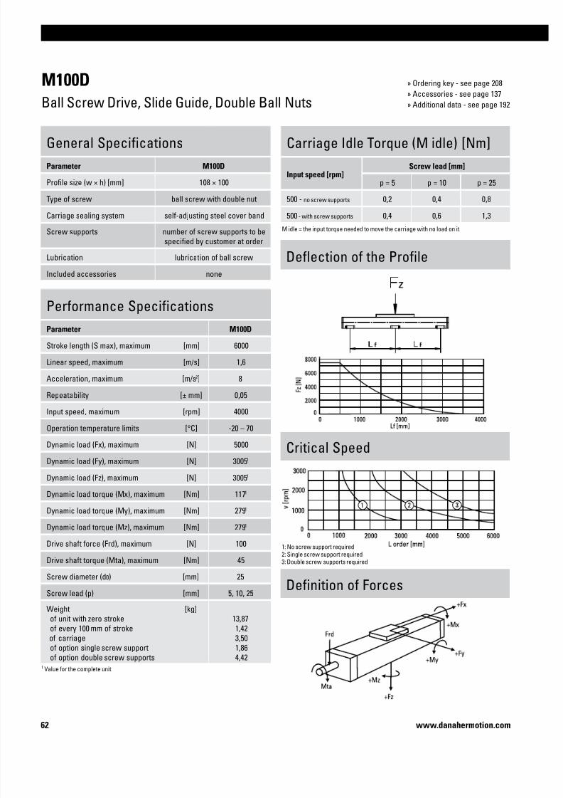
7/23/2019 Linear Actuator Danaher Motion
http://slidepdf.com/reader/full/linear-actuator-danaher-motion 62/22462 www.danahermotion.com
M100D
Ball Screw Drive, Slide Guide, Double Ball Nuts
Performance Specifications
Parameter M100D
Stroke length (S max), maximum [mm] 6000
Linear speed, maximum [m/s] 1,6
Acceleration, maximum [m/s2] 8
Repeatability [± mm] 0,05Input speed, maximum [rpm] 4000
Operation temperature limits [°C] -20 – 70
Dynamic load (Fx), maximum [N] 5000
Dynamic load (Fy), maximum [N] 30051
Dynamic load (Fz), maximum [N] 30051
Dynamic load torque (Mx), maximum [Nm] 1171
Dynamic load torque (My), maximum [Nm] 2791
Dynamic load torque (Mz), maximum [Nm] 2791
Drive shaft force (Frd), maximum [N] 100
Drive shaft torque (Mta), maximum [Nm] 45
Screw diameter (d0) [mm] 25
Screw lead (p) [mm] 5, 10, 25
Weight
of unit with zero stroke
of every 100 mm of stroke
of carriage
of option single screw support
of option double screw supports
[kg]
13,87
1,42
3,50
1,86
4,42
General Specifications
Parameter M100D
Profile size (w × h) [mm] 108 × 100
Type of screw ball screw with double nut
Carriage sealing system self-adjusting steel cover band
Screw supports number of screw supports to be
specified by customer at order
Lubrication lubrication of ball screw
Included accessories none
Deflection of the Profile
Definition of Forces
Carriage Idle Torque (M idle) [Nm]
Input speed [rpm]Screw lead [mm]
p = 5 p = 10 p = 25
500 - no screw supports 0,2 0,4 0,8
500 - with screw supports 0,4 0,6 1,3
M idle = the input torque needed to move the carriage with no load on it.
Critical Speed
1: No screw support required
2: Single screw support required3: Double screw supports required
1 Value for the complete unit
» Ordering key - see page 208
» Accessories - see page 137
» Additional data - see page 192

7/23/2019 Linear Actuator Danaher Motion
http://slidepdf.com/reader/full/linear-actuator-danaher-motion 63/22463
Linear Units
www.danahermotion.com
M100D
Ball Screw Drive, Slide Guide, Double Ball Nuts
Screw support configuration A [mm] B [mm] Ordering length (L order) [mm] Total length (L tot) [mm]
No screw support 1 59 L order = S max + A + B + 306 L tot = L order + 88
Single screw support 31 117 L order = S max + A + B + 306 L tot = L order + 88
Double screw supports 86 172 L order = S max + A + B + 306 L tot = L order + 88
Double Carriages
Parameter M100D
Minimum distance between carriages (Lc) [mm] 350
Dynamic load (Fy), maximum [N] 4508
Dynamic load (Fz), maximum [N] 4508
Dynamic load torque (My), maximum [Nm] Lc1 × 2,254
Dynamic load torque (Mz), maximum [Nm] Lc1 × 2,254
Force required to move second carriage [N] 45
Weight
of unit with zero stroke
of carriages
[kg]
15,43
7,00
A1: depth 9, Heli coil
A2: lubrication holes
A3: ø17/ø10,5 for socket head cap screw M10
A4: depth 10, Heli coil
A5: 100 (L order <= 1 m), 320 (L order > 1 m)
A6: 100 (L order <= 1 m), 430 (L order > 1 m)
1 Value in mm
Screw support configuration A [mm] B [mm] Ordering length (L order) [mm] Total length (L tot) [mm]
No screw support 1 59 L order = S max + A + B + Lc + 306 L tot = L order + 88
Single screw support 31 117 L order = S max + A + B + Lc + 306 L tot = L order + 88
Double screw supports 86 172 L order = S max + A + B + Lc + 306 L tot = L order + 88

7/23/2019 Linear Actuator Danaher Motion
http://slidepdf.com/reader/full/linear-actuator-danaher-motion 64/22464 www.danahermotion.com

7/23/2019 Linear Actuator Danaher Motion
http://slidepdf.com/reader/full/linear-actuator-danaher-motion 65/22465
Linear Units
www.danahermotion.com
Linear Units with Belt Drive and Ball Guide
SpeedLine, Movopart, ForceLine, Microstage
Typical Applications
Typical applications are where medium accuracy, speed and load capability is
required. Typical examples are cutting, welding, glueing and assembly operations
and in materials handling applications such as palletizing and pick and placeoperations.
Velocity
Acceleration
Repeatability
Force
Stiffness
Cost
Maintenance
Noise
Guide Robustness Load Torque

7/23/2019 Linear Actuator Danaher Motion
http://slidepdf.com/reader/full/linear-actuator-danaher-motion 66/22466 www.danahermotion.com
Parameter WH40
Profile size (width × height) [mm] 40 × 40
Stroke length (S max), maximum [mm] 2000
Linear speed, maximum [m/s] 3,0
Dynamic carriage load (Fz), maximum [N] 600
Remarksno cover band
Page 68
Parameter M55 M75 M100
Profile size (width × height) [mm] 58 × 55 86 × 75 108 × 100
Stroke length (S max), maximum [mm] 7000 12000 12000
Linear speed, maximum [m/s] 5,0 5,0 5,0
Dynamic carriage load (Fz), maximum [N] 750 1750 4000
Remarks
Page 76 78 80
Features
• Can be installed in all directions
• Stroke up to 2 m
• Acceleration up to 40 m/s2
• Compact
Features
• Can be installed in all directions
• Self-adjusting stainless steel cover band
• Stroke up to 12 m
• Wash down protected versions available
SpeedLine WH
Movopart M
WH40
M75
Parameter WM60Z WM80Z
Profile size (width × height) [mm] 60 × 60 80 × 80
Stroke length (S max), maximum [mm] 4000 5500
Linear speed, maximum [m/s] 2,5 5,0
Dynamic carriage load (Fz), maximum [N] 1400 2100
Remarks
Page 70 72
Features
• Can be installed in all directions
• Stroke up to 5,5 m
• Speed up to 5 m/s
• Patented plastic cover band
PowerLine WMZ
WM80Z

7/23/2019 Linear Actuator Danaher Motion
http://slidepdf.com/reader/full/linear-actuator-danaher-motion 67/22467
Linear Units
www.danahermotion.com
Parameter MLSM80Z
Profile size (width × height) [mm] 240 × 85
Stroke length (S max), maximum [mm] 5900
Linear speed, maximum [m/s] 5,0
Dynamic carriage load (Fz), maximum [N] 6400
Remarks
Page 82
Features
• Can be installed in all directions
• Patented plastic cover band
• High load capabilities
• Low profile height
ForceLine MLSM
MLSM80Z
WMZ-Series Technical Presentation
Cover bandThe patented self-adjusting
cover band protect the interior of
the unit from the penetration of
dirt, dust and liquids.
Central lubricationOne central lubrication point on
the carriage services the entire
unit resulting in a minimum
maintenace required.
Belt driveThe belt is protected from the
outside ensuring long,
accurate and safe operation.
Ball guidesIntegrated patented ball guides
with hardened steel tracks for
optimum performance.

7/23/2019 Linear Actuator Danaher Motion
http://slidepdf.com/reader/full/linear-actuator-danaher-motion 68/22468 www.danahermotion.com
WH40
Belt Drive, Ball Guide
Performance Specifications
Parameter WH40
Stroke length (S max), maximum [mm] 2000
Linear speed, maximum [m/s] 3,0
Acceleration, maximum [m/s2] 40
Repeatability [± mm] 0,05
Input speed, maximum [rpm] 1800
Operation temperature limits [°C] 0 – 80
Dynamic load (Fx), maximum [N] 3151
Dynamic load (Fy), maximum [N] 4501 / 53002
Dynamic load (Fz), maximum [N] 6001 / 67902
Dynamic load torque (Mx), maximum [Nm] 101 / 322
Dynamic load torque (My), maximum [Nm] 301 / 1902
Dynamic load torque (Mz), maximum [Nm] 301 / 1902
Drive shaft force (Frd), maximum [N] 100
Drive shaft torque (Mta), maximum [Nm] 6
Pulley diameter [mm] 31,83
Stroke per shaft revolution [mm] 100
Weight
of unit with zero stroke of every 100 mm of stroke
of each carriage
[kg]
1,190,15
0,28
General Specifications
Parameter WH40
Profile size (w × h) [mm] 40 × 40
Type of belt 10 AT 5
Carriage sealing system none
Adjustable belt tensioning the belt can be retensioned
by the customer if necessary
Lubrication central lubrication of all parts that
require lubrication
Included accessories 4 × mounting clamps
Carriage Idle Torque, (M idle) [Nm]
Input speed [rpm] Idle torque [Nm]
150 0,1
900 0,3
1800 0,6
M idle = the input torque needed to move the carriage with no load on it.
Force Fx as a Function of the Speed
Definition of Forces
1 Value for the complete unit, also see diagram Force Fx2 Value for the ball guide only
Deflection of the Profile
A mounting clamp must be installed at least at every 750 mm to be able to operate the
maximum load. Less clamps may be required if less load is being operated, see the additional technical data for more information.
» Ordering key - see page 209
» Accessories - see page 137
» Additional data - see page 192

7/23/2019 Linear Actuator Danaher Motion
http://slidepdf.com/reader/full/linear-actuator-danaher-motion 69/22469
Linear Units
www.danahermotion.com
WH40
Belt Drive, Ball Guide
Long Carriage
Parameter WH40
Carriage length [mm] 210
Dynamic load torque (My), maximum [Nm] 50
Dynamic load torque (Mz), maximum [Nm] 50
Weight [kg] 0,43
A1: depth 10
A2: depth 3
A3: lubricating nipple on both sides
A4: socket cap screw ISO4762-M5×12 8.8
A5: ENF inductive sensor rail option kit (optional)
Double Carriages
Parameter WH40
Minimum distance between carriages (L A) [mm] 135
Dynamic load (Fy), maximum [N] 900
Dynamic load (Fz), maximum [N] 1200
Dynamic load torque (My), maximum [Nm] L A 1 × 0,45
Dynamic load torque (Mz), maximum [Nm] L A 1 × 0,60
Force required to move second carriage [N] 2
Total length (L tot) [mm] S max + 265 + L A
A1: depth 10
1 Value in mm

7/23/2019 Linear Actuator Danaher Motion
http://slidepdf.com/reader/full/linear-actuator-danaher-motion 70/22470 www.danahermotion.com
WM60Z
Belt Drive, Ball Guide, Short Carriage
Performance Specifications
Parameter WM60Z
Stroke length (S max), maximum [mm] 4000
Linear speed, maximum [m/s] 2,5
Acceleration, maximum [m/s2] 20
Repeatability [± mm] 0,05
Input speed, maximum [rpm] 1250
Operation temperature limits [°C] 0 – 80
Dynamic load (Fx), maximum [N] 850
Dynamic load (Fy), maximum [N] 14001 / 259302
Dynamic load (Fz), maximum [N] 14001 / 238702
Dynamic load torque (Mx), maximum [Nm] 251 / 4202
Dynamic load torque (My), maximum [Nm] 501 / 3302
Dynamic load torque (Mz), maximum [Nm] 501 / 3602
Drive shaft force (Frd), maximum [N] 150
Drive shaft torque (Mta), maximum [Nm] 17
Pulley diameter [mm] 38,20
Stroke per shaft revolution [mm] 120
Weight
of unit with zero stroke of every 100 mm of stroke
of each carriage
[kg]
4,300,45
1,25
General Specifications
Parameter WM60Z
Profile size (w × h) [mm] 60 × 60
Type of belt 20 ATL 5
Carriage sealing system self-adjusting plastic cover band
Adjustable belt tensioning the belt can be retensioned
by the customer if necessary
Lubrication central lubrication of all parts that
require lubrication
Included accessories 4 × mounting clamps
Carriage Idle Torque, (M idle) [Nm]
Input speed [rpm] Idle torque [Nm]
150 1,6
600 2,5
1250 3,0
M idle = the input torque needed to move the carriage with no load on it.
Force Fx as a Function of the Speed
Definition of Forces
1 Value for the complete unit, also see diagram Force Fx2 Value for the ball guide only
Deflection of the Profile
A mounting clamp must be installed at least at every 750 mm to be able to operate the
maximum load. Less clamps may be required if less load is being operated, see the additional technical data for more information.
» Ordering key - see page 210
» Accessories - see page 137
» Additional data - see page 192

7/23/2019 Linear Actuator Danaher Motion
http://slidepdf.com/reader/full/linear-actuator-danaher-motion 71/22471
Linear Units
www.danahermotion.com
WM60Z
Belt Drive, Ball Guide, Short Carriage
A1: depth 15
A2: depth 4
A3: depth 11A4: socket cap screw ISO4762-M6×20 8.8
A5: ENF inductive sensor rail option kit (optional)
A6: tapered lubricating nipple to DIN71412 AM6 on fixed-bearing side as standard feature
A7: can be changed over to one of three alternative lubrications points by the customer
Double Short Carriages
Parameter WM60Z
Minimum distance between carriages (L A) [mm] 255
Dynamic load (Fy), maximum [N] 2800
Dynamic load (Fz), maximum [N] 2800
Dynamic load torque (My), maximum [Nm] L A 1 × 1,4
Dynamic load torque (Mz), maximum [Nm] L A 1 × 1,4
Force required to move second carriage [N] 180
Total length (L tot) [mm] S max + 420 + L A
1 Value in mm

7/23/2019 Linear Actuator Danaher Motion
http://slidepdf.com/reader/full/linear-actuator-danaher-motion 72/22472 www.danahermotion.com
WM80Z
Belt Drive, Ball Guide, Standard Carriage
Performance Specifications
Parameter WM80Z
Stroke length (S max), maximum [mm] 5400
Linear speed, maximum [m/s] 5,0
Acceleration, maximum [m/s2] 20
Repeatability [± mm] 0,05
Input speed, maximum [rpm] 885
Operation temperature limits [°C] 0 – 80
Dynamic load (Fx), maximum [N] 1470
Dynamic load (Fy), maximum [N] 30001 / 574202
Dynamic load (Fz), maximum [N] 30001 / 549602
Dynamic load torque (Mx), maximum [Nm] 1501 / 13702
Dynamic load torque (My), maximum [Nm] 3001 / 42002
Dynamic load torque (Mz), maximum [Nm] 3001 / 43902
Drive shaft force (Frd), maximum [N] 600
Drive shaft torque (Mta), maximum [Nm] 40
Pulley diameter [mm] 54,11
Stroke per shaft revolution [mm] 170
Weight
of unit with zero stroke of every 100 mm of stroke
of each carriage
[kg]
11,20,8
3,4
General Specifications
Parameter WM80Z
Profile size (w × h) [mm] 80 × 80
Type of belt 25 AT 10
Carriage sealing system self-adjusting plastic cover band
Adjustable belt tensioning the belt can be retensioned
by the customer if necessary
Lubrication central lubrication of all parts that
require lubrication
Included accessories 4 × mounting clamps
Carriage Idle Torque, (M idle) [Nm]
Input speed [rpm] Idle torque [Nm]
150 6,5
450 7,7
885 9,3
M idle = the input torque needed to move the carriage with no load on it.
Force Fx as a Function of the Speed
Definition of Forces
1 Value for the complete unit, also see diagram Force Fx2 Value for the ball guide only
Deflection of the Profile
A mounting clamp must be installed at least at every 750 mm to be able to operate the
maximum load. Less clamps may be required if less load is being operated, see the additional technical data for more information.
» Ordering key - see page 210
» Accessories - see page 137
» Additional data - see page 192

7/23/2019 Linear Actuator Danaher Motion
http://slidepdf.com/reader/full/linear-actuator-danaher-motion 73/22473
Linear Units
www.danahermotion.com
WM80Z
Belt Drive, Ball Guide, Standard Carriage
A1: depth 15
A2: depth 2,5
A3: depth 12A4: socket cap screw ISO4762-M6×20 8.8
A5: ENF inductive sensor rail option kit (optional)
A6: tapered lubricating nipple to DIN71412 AM6 on fixed-bearing side as standard feature
A7: can be changed over to one of three alternative lubrications points by the customer
Double Carriages
Parameter WM80Z
Minimum distance between carriages (L A) [mm] 360
Dynamic load (Fy), maximum [N] 6000
Dynamic load (Fz), maximum [N] 6000
Dynamic load torque (My), maximum [Nm] L A 1 × 3
Dynamic load torque (Mz), maximum [Nm] L A 1 × 3
Force required to move second carriage [N] 250
Total length (L tot) [mm] S max + 590 + L A
1 Value in mm
Long Carriage
Parameter WM80Z
Carriage length [mm] 450
Dynamic load torque (My), maximum [Nm] 750
Dynamic load torque (Mz), maximum [Nm] 750
Weight [kg] 5,1A1: depth 12 mm

7/23/2019 Linear Actuator Danaher Motion
http://slidepdf.com/reader/full/linear-actuator-danaher-motion 74/22474 www.danahermotion.com
WM80Z
Belt Drive, Ball Guide, Short Carriage
» Ordering key - see page 210
» Accessories - see page 137
» Additional data - see page 192
Performance Specifications
Parameter WM80Z
Stroke length (S max), maximum [mm] 5500
Linear speed, maximum [m/s] 5,0
Acceleration, maximum [m/s2] 20
Repeatability [± mm] 0,05
Input speed, maximum [rpm] 885
Operation temperature limits [°C] 0 – 80
Dynamic load (Fx), maximum [N] 1470
Dynamic load (Fy), maximum [N] 21001 / 374502
Dynamic load (Fz), maximum [N] 21001 / 358402
Dynamic load torque (Mx), maximum [Nm] 681 / 8902
Dynamic load torque (My), maximum [Nm] 1351 / 5802
Dynamic load torque (Mz), maximum [Nm] 1351 / 6102
Drive shaft force (Frd), maximum [N] 600
Drive shaft torque (Mta), maximum [Nm] 40
Pulley diameter [mm] 54,11
Stroke per shaft revolution [mm] 170
Weight
of unit with zero stroke of every 100 mm of stroke
of each carriage
[kg]
9,20,8
2,1
General Specifications
Parameter WM80Z
Profile size (w × h) [mm] 80 × 80
Type of belt 25 AT 10
Carriage sealing system self-adjusting plastic cover band
Adjustable belt tensioning the belt can be retensioned
by the customer if necessary
Lubrication central lubrication of all parts that
require lubrication
Included accessories 4 × mounting clamps
Carriage Idle Torque, (M idle) [Nm]
Input speed [rpm] Idle torque [Nm]
150 4,0
450 5,4
885 6,2
M idle = the input torque needed to move the carriage with no load on it.
Force Fx as a Function of the Speed
Definition of Forces
1 Value for the complete unit, also see diagram Force Fx2 Value for the ball guide only
Deflection of the Profile
A mounting clamp must be installed at least at every 750 mm to be able to operate the
maximum load. Less clamps may be required if less load is being operated, see the additional technical data for more information.

7/23/2019 Linear Actuator Danaher Motion
http://slidepdf.com/reader/full/linear-actuator-danaher-motion 75/22475
Linear Units
www.danahermotion.com
WM80Z
Belt Drive, Ball Guide, Short Carriage
A1: depth 15
A2: depth 2,5
A3: depth 12A4: socket cap screw ISO4762-M6×20 8.8
A5: ENF inductive sensor rail option kit (optional)
A6: tapered lubricating nipple to DIN71412 AM6 on fixed-bearing side as standard feature
A7: can be changed over to one of three alternative lubrications points by the customer
Double Short Carriages
Parameter WM80Z
Minimum distance between carriages (L A) [mm] 280
Dynamic load (Fy), maximum [N] 4200
Dynamic load (Fz), maximum [N] 4200
Dynamic load torque (My), maximum [Nm] L A 1 × 2,1
Dynamic load torque (Mz), maximum [Nm] L A 1 × 2,1
Force required to move second carriage [N] 225
Total length (L tot) [mm] S max + 490 + L A
1 Value in mm

7/23/2019 Linear Actuator Danaher Motion
http://slidepdf.com/reader/full/linear-actuator-danaher-motion 76/22476 www.danahermotion.com
M55
Belt Drive, Ball Guide
Carriage Idle Torque (M idle) [Nm]
Input speed [rpm] Single Carriage Double Carriages
150 1,0 1,9
M idle = the input torque needed to move the carriage with no load on it.
Performance Specifications
Parameter M55
Stroke length (S max), maximum [mm] 7000
Linear speed, maximum [m/s] 5,0
Acceleration, maximum [m/s2] 40
Repeatability [± mm] 0,1
Input speed, maximum [rpm] 2850
Operation temperature limits [°C] -20 – 70
Dynamic load (Fx), maximum
< 2,5 m/s
> 2,5 m/s
[N]
400
200
Dynamic load (Fy), maximum [N] 7501 / 54352
Dynamic load (Fz), maximum [N] 7501 / 69682
Dynamic load torque (Mx), maximum [Nm] 51 / 492
Dynamic load torque (My), maximum [Nm] 291 / 2122
Dynamic load torque (Mz), maximum [Nm] 291 / 2122
Drive shaft force (Frd), maximum [N] 200
Drive shaft torque (Mta), maximum [Nm] 12
Pulley diameter [mm] 33,42
Stroke per shaft revolution [mm] 105
Weight
of unit with zero stroke
of every 100 mm of stroke of carriage
[kg]
4,80
0,531,20
General Specifications
Parameter M55
Profile size (w × h) [mm] 58 × 55
Type of belt 22-STD SM5-HP
Carriage sealing system self-adjusting steel cover band
Adjustable belt tensioning the belt can be retensioned
by the customer if necessary
Lubrication lubrication of ball
guide carriages
Included accessories none
Deflection of the Profile
Definition of Forces
1 Value for the complete unit2 Value for the ball guide only
» Ordering key - see page 211
» Accessories - see page 137
» Additional data - see page 192

7/23/2019 Linear Actuator Danaher Motion
http://slidepdf.com/reader/full/linear-actuator-danaher-motion 77/22477
Linear Units
www.danahermotion.com
1 Value in mm
M55
Belt Drive, Ball Guide
Double Carriages
Parameter M55
Minimum distance between carriages (Lc) [mm] 250
Dynamic load (Fy), maximum [N] 1125
Dynamic load (Fz), maximum [N] 1125
Dynamic load torque (My), maximum [Nm] Lc1 × 0,56
Dynamic load torque (Mz), maximum [Nm] Lc1 × 0,56
Force required to move second carriage [N] 2
Ordering length (L order) [mm] S max + Lc + 320
Total length (L tot] [mm] L order + 52
Weight
of unit with zero stroke
of carriages
[kg]
7,06
2,40
A1: depth 10, Heli coil
A2: lubrication holes
A3: ø9,5/ø5,5 for socket head cap screw M5
A4: depth 7,5 Heli coil

7/23/2019 Linear Actuator Danaher Motion
http://slidepdf.com/reader/full/linear-actuator-danaher-motion 78/22478 www.danahermotion.com
M75
Belt Drive, Ball Guide
Carriage Idle Torque (M idle) [Nm]
Input speed [rpm] Single Carriage Double Carriages
150 1,0 1,9
M idle = the input torque needed to move the carriage with no load on it.
Performance Specifications
Parameter M75
Stroke length (S max), maximum [mm] 12000
Linear speed, maximum [m/s] 5,0
Acceleration, maximum [m/s2] 40
Repeatability [± mm] 0,1
Input speed, maximum [rpm] 2300
Operation temperature limits [°C] -20 – 70
Dynamic load (Fx), maximum
< 2,5 m/s
> 2,5 m/s
[N]
900
450
Dynamic load (Fy), maximum [N] 17501 / 164132
Dynamic load (Fz), maximum [N] 17501 / 309682
Dynamic load torque (Mx), maximum [Nm] 161 / 1502
Dynamic load torque (My), maximum [Nm] 841 / 7432
Dynamic load torque (Mz), maximum [Nm] 841 / 7872
Drive shaft force (Frd), maximum [N] 600
Drive shaft torque (Mta), maximum [Nm] 30
Pulley diameter [mm] 41,38
Stroke per shaft revolution [mm] 130
Weight
of unit with zero stroke
of every 100 mm of stroke of carriage
[kg]
7,50
0,882,00
General Specifications
Parameter M75
Profile size (w × h) [mm] 86 × 75
Type of belt STD5-40
Carriage sealing system self-adjusting steel cover band
Adjustable belt tensioning the belt can be retensioned
by the customer if necessary
Lubrication lubrication of ball
guide carriages
Included accessories none
1 Value for the complete unit2 Value for the ball guide only
Deflection of the Profile
Definition of Forces
» Ordering key - see page 211
» Accessories - see page 137
» Additional data - see page 192

7/23/2019 Linear Actuator Danaher Motion
http://slidepdf.com/reader/full/linear-actuator-danaher-motion 79/22479
Linear Units
www.danahermotion.com
M75
Belt Drive, Ball Guide
Double Carriages
Parameter M75
Minimum distance between carriages (Lc) [mm] 250
Dynamic load (Fy), maximum [N] 2625
Dynamic load (Fz), maximum [N] 2625
Dynamic load torque (My), maximum [Nm] Lc1 × 1,313
Dynamic load torque (Mz), maximum [Nm] Lc1 × 1,313
Force required to move second carriage [N] 2
Ordering length (L order) [mm] S max + Lc + 315
Total length (L tot] [mm] L order + 52
Weight
of unit with zero stroke
of carriages
[kg]
11,67
4,00
A1: depth 9, Heli coil
A2: lubrication holes
A3: ø13,5/ø8,5 for socket head cap screw M8
A4: depth 8, Heli coil
1 Value in mm

7/23/2019 Linear Actuator Danaher Motion
http://slidepdf.com/reader/full/linear-actuator-danaher-motion 80/22480 www.danahermotion.com
M100
Belt Drive, Ball Guide
Carriage Idle Torque (M idle) [Nm]
Input speed [rpm] Single Carriage Double Carriages
150 1,6 3,1
M idle = the input torque needed to move the carriage with no load on it.
Performance Specifications
Parameter M100
Stroke length (S max), maximum [mm] 12000
Linear speed, maximum [m/s] 5,0
Acceleration, maximum [m/s2] 40
Repeatability [± mm] 0,1
Input speed, maximum [rpm] 1700
Operation temperature limits [°C] -20 – 70
Dynamic load (Fx), maximum
< 2,5 m/s
> 2,5 m/s
[N]
1250
625
Dynamic load (Fy), maximum [N] 40001 / 263782
Dynamic load (Fz), maximum [N] 40001 / 497702
Dynamic load torque (Mx), maximum [Nm] 431 / 2832
Dynamic load torque (My), maximum [Nm] 2801 / 17422
Dynamic load torque (Mz), maximum [Nm] 2801 / 18462
Drive shaft force (Frd), maximum [N] 1000
Drive shaft torque (Mta), maximum [Nm] 45
Pulley diameter [mm] 56,02
Stroke per shaft revolution [mm] 176
Weight
of unit with zero stroke
of every 100 mm of stroke of carriage
[kg]
11,61
1,43 2,20
General Specifications
Parameter M100
Profile size (w × h) [mm] 108 × 100
Type of belt STD8-50
Carriage sealing system self-adjusting steel cover band
Adjustable belt tensioning the belt can be retensioned
by the customer if necessary
Lubrication lubrication of ball
guide carriages
Included accessories none
Deflection of the Profile
Definition of Forces
» Ordering key - see page 211
» Accessories - see page 137
» Additional data - see page 192

7/23/2019 Linear Actuator Danaher Motion
http://slidepdf.com/reader/full/linear-actuator-danaher-motion 81/22481
Linear Units
www.danahermotion.com
M100
Belt Drive, Ball Guide
Double Carriages
Parameter M100
Minimum distance between carriages (Lc) [mm] 350
Dynamic load (Fy), maximum [N] 6000
Dynamic load (Fz), maximum [N] 6000
Dynamic load torque (My), maximum [Nm] Lc1 × 3
Dynamic load torque (Mz), maximum [Nm] Lc1 × 3
Force required to move second carriage [N] 2
Ordering length (L order) [mm] S max + Lc + 405
Total length (L tot] [mm] L order + 56
Weight
of unit with zero stroke
of carriagess
[kg]
18,92
4,40
A1: depth 9, Heli coilA2: lubrication hole
A3: lubrication hole (no hole if L order is < 856 mm)A4: ø17/ø10,5 for socket head cap screw M10
1
Value in mm

7/23/2019 Linear Actuator Danaher Motion
http://slidepdf.com/reader/full/linear-actuator-danaher-motion 82/22482 www.danahermotion.com
MLSM80Z
Belt Drive, Ball Guide
Performance Specifications
Parameter MLSM80Z
Stroke length (S max), maximum [mm] 5900
Linear speed, maximum [m/s] 5,0
Acceleration, maximum [m/s2] 20
Repeatability [± mm] 0,05
Input speed, maximum [rpm] 1500
Operation temperature limits [°C] 0 – 80
Dynamic load (Fx), maximum [N] 50003
Dynamic load (Fy), maximum [N] 64001 / 718602
Dynamic load (Fz), maximum [N] 64001 / 718602
Dynamic load torque (Mx), maximum [Nm] 6001 / 58902
Dynamic load torque (My), maximum [Nm] 7201 / 66402
Dynamic load torque (Mz), maximum [Nm] 7201 / 66402
Drive shaft force (Frd), maximum [N] 700
Drive shaft torque (Mta), maximum [Nm] 150
Pulley diameter [mm] 63,66
Stroke per shaft revolution [mm] 200
Weight
of unit with zero stroke of every 100 mm of stroke
of each carriage
[kg]
30,8 2,2
9,6
General Specifications
Parameter MLSM80Z
Profile size (w × h) [mm] 240 × 85
Type of belt 75 ATL 10
Carriage sealing system plastic cover band
Adjustable belt tensioning the belt can be retensioned
by the customer if necessary
Lubrication central lubrication of all parts that
require lubrication
Included accessories 4 × mounting clamps
Carriage Idle Torque, (M idle) [Nm]
Input speed [rpm] Idle torque [Nm]
150 8,5
750 12
1500 14,5
M idle = the input torque needed to move the carriage with no load on it.
Force Fx as a Function of the Speed
Definition of Forces
1 Value for the complete unit2 Value for the ball guide only3 See diagram Force Fx
Deflection of the Profile
A mounting clamp must be installed at least at every 750 mm to be able to operate the
maximum load. Less clamps may be required if less load is being operated, see the additional technical data for more information.
» Ordering key - see page 212
» Accessories - see page 137
» Additional data - see page 192

7/23/2019 Linear Actuator Danaher Motion
http://slidepdf.com/reader/full/linear-actuator-danaher-motion 83/22483
Linear Units
www.danahermotion.com
MLSM80Z
Belt Drive, Ball Guide
Long Carriage
Parameter MLSM80Z
Carriage length [mm] 500
Dynamic load torque (My), maximum [Nm] 1400
Dynamic load torque (Mz), maximum [Nm] 1400
Weight [kg] 14
A1: depth 18A2: depth 4
A3: depth 15A4: socket cap screw ISO4762-M8×20 8.8
A5: ENF inductive sensor rail option kit (optional)A6: tapered lubricating nipple to DIN71412 M8×1 on fixed-bearing side as standard feature
A7: can be changed over to one of the three alternative lubricating points by the customer
Double Carriages
Parameter MLSM80Z
Minimum distance between carriages (L A) [mm] 400
Dynamic load (Fy), maximum [N] 12800
Dynamic load (Fz), maximum [N] 12800
Dynamic load torque (My), maximum [Nm] L A 1 × 6,4
Dynamic load torque (Mz), maximum [Nm] L A 1 × 6,4
Force required to move second carriage [N] 350
Total length (L tot) [mm] S max + 600 + L A
A1: depth 15
1 Value in mm

7/23/2019 Linear Actuator Danaher Motion
http://slidepdf.com/reader/full/linear-actuator-danaher-motion 84/22484 www.danahermotion.com

7/23/2019 Linear Actuator Danaher Motion
http://slidepdf.com/reader/full/linear-actuator-danaher-motion 85/22485
Linear Units
www.danahermotion.com
Linear Units with Belt Drive and Slide Guide
Movopart
Typical Applications
Typical applications are where low loads need to be moved at medium speed and
high acceleration at low cost. These units are suited to harsh environments. Typical
examples are for machines in the food, chemical, paper and wood working industry,in materials handling, cutting, scanning and printing applications.
Velocity
Acceleration
Repeatability
Force
Stiffness
Cost
Maintenance
Noise
Guide Robustness Load Torque

7/23/2019 Linear Actuator Danaher Motion
http://slidepdf.com/reader/full/linear-actuator-danaher-motion 86/22486 www.danahermotion.com
Parameter M50
Profile size (width × height) [mm] 50 × 50
Stroke length (S max), maximum [mm] 5000
Linear speed, maximum [m/s] 5,0
Dynamic carriage load (Fz), maximum [N] 400
Remarks no cover band
Page 88
Features
• Can be installed in all directions
• Patented self-adjusting prism slide guides
• Resistant to shock loads and vibrations
• Low cost
Movopart M
M50
Parameter M55 M75 M100
Profile size (width × height) [mm] 58 × 55 86 × 75 108 × 100
Stroke length (S max), maximum [mm] 7000 12000 12000
Linear speed, maximum [m/s] 5,0 5,0 5,0
Dynamic carriage load (Fz), maximum [N] 400 1485 3005
Remarks
Page 90 92 94
Features
• Can be installed in all directions
• Self-adjusting stainless steel cover band
• Patented self-adjusting prism slide guides
• Wash down and chemical protected versions available
Movopart M
M100

7/23/2019 Linear Actuator Danaher Motion
http://slidepdf.com/reader/full/linear-actuator-danaher-motion 87/22487
Linear Units
www.danahermotion.com
M-Series Technical Presentation
Cover bandThe self-adjusting magnetically
sealed stainless steel cover band
protect the unit from the penetration
of dirt, dust and liquids.
Environmental protectionThe unit can as standard operate in harsh
environments but is also available in wash
down or chemically protected versions for the
thoughest environments.
Belt driveThe belt runs on the inside of the
profile and can easily be re-tensioned
without removing the load from the
carriage.
Prism slide guidesThe patented self aligning prism slide
guides are accurate, durable and
are resistant to vibrations and shock
loads.

7/23/2019 Linear Actuator Danaher Motion
http://slidepdf.com/reader/full/linear-actuator-danaher-motion 88/22488 www.danahermotion.com
M50
Belt Drive, Slide Guide
Performance Specifications
Parameter M50
Stroke length (S max), maximum [mm] 5000
Linear speed, maximum [m/s] 5,0
Acceleration, maximum [m/s2] 40
Repeatability [± mm] 0,2
Input speed, maximum [rpm] 2300
Operation temperature limits [°C] -20 – 70
Dynamic load (Fx), maximum
< 2,5 m/s
> 2,5 m/s
[N]
400
200
Dynamic load (Fy), maximum [N] 4001
Dynamic load (Fz), maximum [N] 4001
Dynamic load torque (Mx), maximum [Nm] 51
Dynamic load torque (My), maximum [Nm] 211
Dynamic load torque (Mz), maximum [Nm] 211
Drive shaft force (Frd), maximum [N] 350
Drive shaft torque (Mta), maximum [Nm] 10
Pulley diameter [mm] 41,38
Stroke per shaft revolution [mm] 130
Weight
of unit with zero stroke
of every 100 mm of stroke of carriage
[kg]
0,71
0,960,33
General Specifications
Parameter M50
Profile size (w × h) [mm] 50 × 50
Type of belt GT 5MR-19
Carriage sealing system none
Adjustable belt tensioning the belt can be retensioned
by the customer if necessary
Lubrication lubricated for life
Included accessories none
Carriage Idle Torque (M idle) [Nm]
Input speed [rpm] Idle torque [Nm]
150 2,1
M idle = the input torque needed to move the carriage with no load on it.
Deflection of the Profile
Definition of Forces
1 Value for the complete unit
» Ordering key - see page 213
» Accessories - see page 137
» Additional data - see page 193

7/23/2019 Linear Actuator Danaher Motion
http://slidepdf.com/reader/full/linear-actuator-danaher-motion 89/22489
Linear Units
www.danahermotion.com
M50
Belt Drive, Slide Guide
A1: depth 8,5
A2: ø6,5 for M6 screwA3: depth 9, Heli coil

7/23/2019 Linear Actuator Danaher Motion
http://slidepdf.com/reader/full/linear-actuator-danaher-motion 90/22490 www.danahermotion.com
M55
Belt Drive, Slide Guide
Performance Specifications
Parameter M55
Stroke length (S max), maximum [mm] 7000
Linear speed, maximum [m/s] 5,0
Acceleration, maximum [m/s2] 40
Repeatability [± mm] 0,2
Input speed, maximum [rpm] 2850
Operation temperature limits [°C] -20 – 70
Dynamic load (Fx), maximum
< 2,5 m/s
> 2,5 m/s
[N]
400
200
Dynamic load (Fy), maximum [N] 4001
Dynamic load (Fz), maximum [N] 4001
Dynamic load torque (Mx), maximum [Nm] 91
Dynamic load torque (My), maximum [Nm] 211
Dynamic load torque (Mz), maximum [Nm] 211
Drive shaft force (Frd), maximum [N] 200
Drive shaft torque (Mta), maximum [Nm] 7
Pulley diameter [mm] 33,42
Stroke per shaft revolution [mm] 105
Weight
of unit with zero stroke
of every 100 mm of stroke of carriage
[kg]
4,10
0,411,10
General Specifications
Parameter M55
Profile size (w × h) [mm] 58 × 50
Type of belt 22-STD SM5-HP
Carriage sealing system self-adjusting steel cover band
Adjustable belt tensioning the belt can be retensioned
by the customer if necessary
Lubrication lubricated for life
Included accessories none
Carriage Idle Torque (M idle) [Nm]
Input speed [rpm] Single Carriage Double Carriages
150 2,1 3,8
M idle = the input torque needed to move the carriage with no load on it.
Deflection of the Profile
Definition of Forces
1 Value for the complete unit
» Ordering key - see page 213
» Accessories - see page 137
» Additional data - see page 193

7/23/2019 Linear Actuator Danaher Motion
http://slidepdf.com/reader/full/linear-actuator-danaher-motion 91/22491
Linear Units
www.danahermotion.com
M55
Belt Drive, Slide Guide
A1: depth 10, Heli coil
A2: lubrication holes
A3: ø9,5/ø5,5 for socket head cap screw M5
A4: depth 7,5, Heli coil
Double Carriages
Parameter M55
Minimum distance between carriages (Lc) [mm] 200
Dynamic load (Fy), maximum [N] 600
Dynamic load (Fz), maximum [N] 600
Dynamic load torque (My), maximum [Nm] Lc1 × 0,3
Dynamic load torque (Mz), maximum [Nm] Lc1 × 0,3
Force required to move second carriage [N] 35
Ordering length (L order) [mm] S max + Lc + 260
Total length (L tot] [mm] L order + 53
Weightof unit with zero stroke
of carriages
[kg]6,00
2,20
1 Value in mm

7/23/2019 Linear Actuator Danaher Motion
http://slidepdf.com/reader/full/linear-actuator-danaher-motion 92/22492 www.danahermotion.com
M75
Belt Drive, Slide Guide
Performance Specifications
Parameter M75
Stroke length (S max), maximum [mm] 12000
Linear speed, maximum [m/s] 5,0
Acceleration, maximum [m/s2] 40
Repeatability [± mm] 0,2
Input speed, maximum [rpm] 2300
Operation temperature limits [°C] -20 – 70
Dynamic load (Fx), maximum
< 2,5 m/s
> 2,5 m/s
[N]
900
450
Dynamic load (Fy), maximum [N] 14851
Dynamic load (Fz), maximum [N] 14851
Dynamic load torque (Mx), maximum [Nm] 491
Dynamic load torque (My), maximum [Nm] 851
Dynamic load torque (Mz), maximum [Nm] 851
Drive shaft force (Frd), maximum [N] 600
Drive shaft torque (Mta), maximum [Nm] 30
Pulley diameter [mm] 41,38
Stroke per shaft revolution [mm] 130
Weight
of unit with zero stroke
of every 100 mm of stroke of carriage
[kg]
6,30
0,671,50
General Specifications
Parameter M75
Profile size (w × h) [mm] 86 × 75
Type of belt STD5-40
Carriage sealing system self-adjusting steel cover band
Adjustable belt tensioning the belt can be retensioned
by the customer if necessary
Lubrication lubricated for life
Included accessories none
Carriage Idle Torque (M idle) [Nm]
Input speed [rpm] Single Carriage Double Carriages
150 2,2 4,0
M idle = the input torque needed to move the carriage with no load on it.
Deflection of the Profile
Definition of Forces
1 Value for the complete unit
» Ordering key - see page 213
» Accessories - see page 137
» Additional data - see page 193

7/23/2019 Linear Actuator Danaher Motion
http://slidepdf.com/reader/full/linear-actuator-danaher-motion 93/22493
Linear Units
www.danahermotion.com
M75
Belt Drive, Slide Guide
A1: depth 9, Heli coil
A2: lubrication holes
A3: ø13,5/ø8,5 for socket head cap screw M8
A4: depth 8, Heli coil
Double Carriages
Parameter M75
Minimum distance between carriages (Lc) [mm] 250
Dynamic load (Fy), maximum [N] 2227
Dynamic load (Fz), maximum [N] 2227
Dynamic load torque (My), maximum [Nm] Lc1 × 1,114
Dynamic load torque (Mz), maximum [Nm] Lc1 × 1,114
Force required to move second carriage [N] 40
Ordering length (L order) [mm] S max + Lc + 315
Total length (L tot] [mm] L order + 53
Weight
of unit with zero stroke
of carriages
[kg]
9,50
3,001 Value in mm

7/23/2019 Linear Actuator Danaher Motion
http://slidepdf.com/reader/full/linear-actuator-danaher-motion 94/22494 www.danahermotion.com
M100
Belt Drive, Slide Guide
Performance Specifications
Parameter M100
Stroke length (S max), maximum [mm] 12000
Linear speed, maximum [m/s] 5,0
Acceleration, maximum [m/s2] 40
Repeatability [± mm] 0,2
Input speed, maximum [rpm] 1700
Operation temperature limits [°C] -20 – 70
Dynamic load (Fx), maximum
< 2,5 m/s
> 2,5 m/s
[N]
1250
625
Dynamic load (Fy), maximum [N] 30051
Dynamic load (Fz), maximum [N] 30051
Dynamic load torque (Mx), maximum [Nm] 1171
Dynamic load torque (My), maximum [Nm] 2791
Dynamic load torque (Mz), maximum [Nm] 2791
Drive shaft force (Frd), maximum [N] 1000
Drive shaft torque (Mta), maximum [Nm] 45
Pulley diameter [mm] 56,02
Stroke per shaft revolution [mm] 176
Weight
of unit with zero stroke
of every 100 mm of stroke of carriage
[kg]
11,10
1,162,40
General Specifications
Parameter M100
Profile size (w × h) [mm] 108 × 100
Type of belt STD8-50
Carriage sealing system self-adjusting steel cover band
Adjustable belt tensioning the belt can be retensioned
by the customer if necessary
Lubrication lubricated for life
Included accessories none
Carriage Idle Torque (M idle) [Nm]
Input speed [rpm] Single Carriage Double Carriages
150 3,8 5,8
M idle = the input torque needed to move the carriage with no load on it.
Deflection of the Profile
Definition of Forces
1 Value for the complete unit
» Ordering key - see page 213
» Accessories - see page 137
» Additional data - see page 193

7/23/2019 Linear Actuator Danaher Motion
http://slidepdf.com/reader/full/linear-actuator-danaher-motion 95/22495
Linear Units
www.danahermotion.com
M100
Belt Drive, Slide Guide
Double Carriages
Parameter M100
Minimum distance between carriages (Lc) [mm] 350
Dynamic load (Fy), maximum [N] 4508
Dynamic load (Fz), maximum [N] 4508
Dynamic load torque (My), maximum [Nm] Lc1 × 2,254
Dynamic load torque (Mz), maximum [Nm] Lc1 × 2,254
Force required to move second carriage [N] 45
Ordering length (L order) [mm] S max + Lc + 375
Total length (L tot] [mm] L order + 56
Weight
of unit with zero stroke
of carriages
[kg]
17,40
4,80
A1: Depth 9, Heli coil
A2: lubrication holes
A3: ø17/ø10,5 for socket head cap screw M10
A4: depth 10, Heli coil
A5: 170 (L order <= 1 m), 270 (L order > 1 m)
A6: 186 (L order < = 1 m), 436 (L order > 1 m)
1 Value in mm

7/23/2019 Linear Actuator Danaher Motion
http://slidepdf.com/reader/full/linear-actuator-danaher-motion 96/22496 www.danahermotion.com

7/23/2019 Linear Actuator Danaher Motion
http://slidepdf.com/reader/full/linear-actuator-danaher-motion 97/22497
Linear Units
www.danahermotion.com
Linear Units with Belt Drive and Wheel Guide
SpeedLine, ForceLine
Typical Applications
Typical applications are where low to medium loads needs to be moved at high
speed and acceleration. Typical examples are in packaging, cutting, pick and place
and materials handling applications where the cycle times are critical.
Velocity
Acceleration
Repeatability
Force
Stiffness
Cost
Maintenance
Noise
Guide Robustness Load Torque

7/23/2019 Linear Actuator Danaher Motion
http://slidepdf.com/reader/full/linear-actuator-danaher-motion 98/22498 www.danahermotion.com
Belt driveThe steel reinforced belt is
wear resistant, highly efficient
and very accurate even at high
speeds and loads.
Parameter WH50 WH80 WH120
Profile size (width × height) [mm] 50 × 50 80 × 80 120 × 110
Stroke length (S max), maximum [mm] 3000 11000 11000
Linear speed, maximum [m/s] 6,5 10,0 10,0
Dynamic carriage load (Fz), maximum [N] 730 2100 9300
Remarks external wheel guides
no cover band
external wheel guides
no cover band
external wheel guides
no cover band
Page 100 102 104
Features
• Can be installed in all directions
• Speed up to 11 m/s
• Acceleration up to 40 m/s2
• Stroke up to 11 m
SpeedLine WH
WH80
WH-Series Technical Presentation
Belt tensioningThe belt can easily be replaced
or re-tensioned from the outside
of the unit without the load being
removed from the carriage.
Wheel guidesThe H-type arrangement of the
guides allows fast moves and
high forces and moments.
Central lubricationThe guides are lubricated from
a central point that are easy and
fast to access.

7/23/2019 Linear Actuator Danaher Motion
http://slidepdf.com/reader/full/linear-actuator-danaher-motion 99/22499
Linear Units
www.danahermotion.com
Parameter MLSH60Z MLSH80Z
Profile size (width × height) [mm] 160 × 65 240 × 85
Stroke length (S max), maximum [mm] 5500 5900
Linear speed, maximum [m/s] 10,0 10,0
Dynamic carriage load (Fz), maximum [N] 3000 5000
Remarks internal wheel guides internal wheel guides
Page 106 108
Features
• Can be installed in all directions
• Patented plastic cover band
• Speed up to 10 m/s
• Low profile height
ForceLine MLSH
MLSH60Z
Cover bandThe patented self-adjusting
cover band protect the interior of
the unit from the penetration of
dirt, dust and liquids.
Belt tensioningThe belt can easily be
re-tensioned from the outside of
the unit without the load being
removed from the carriage.
Wheel guidesThe robust wheel guides runs
inside of the profile providing
superior motion dynamics.
Unique profileThe unique design of the profile
guarantees the highest performance
and protection of the guides and belt.
MLSH-Series Technical Presentation
Belt driveThe highly dynamic and accurate
belt is protected by the cover
band ensuring long and trouble
free operation.

7/23/2019 Linear Actuator Danaher Motion
http://slidepdf.com/reader/full/linear-actuator-danaher-motion 100/224100 www.danahermotion.com
WH50
Belt Drive, Wheel Guide
Performance Specifications
Parameter WH50
Stroke length (S max), maximum [mm] 3000
Linear speed, maximum [m/s] 6,5
Acceleration, maximum [m/s2] 40
Repeatability [± mm] 0,05
Input speed, maximum [rpm] 3250
Operation temperature limits [°C] 0 – 80
Dynamic load (Fx), maximum [N] 6703
Dynamic load (Fy), maximum [N] 4151 / 28202
Dynamic load (Fz), maximum [N] 7301 / 50802
Dynamic load torque (Mx), maximum [Nm] 161 / 992
Dynamic load torque (My), maximum [Nm] 871 / 5002
Dynamic load torque (Mz), maximum [Nm] 501 / 2802
Drive shaft force (Frd), maximum [N] 150
Drive shaft torque (Mta), maximum [Nm] 17
Pulley diameter [mm] 38,2
Stroke per shaft revolution [mm] 120
Weight
of unit with zero stroke of every 100 mm of stroke
of each carriage
[kg]
3,500,44
0,90
General Specifications
Parameter WH50
Profile size (w × h) [mm] 50 × 50
Type of belt 16ATL5
Carriage sealing system none
Adjustable belt tensioning the belt can be retensioned
by the customer if necessary
Lubrication lubrication og guiding surfaces
Included accessories 4 × mounting clamps
Carriage Idle Torque, (M idle) [Nm]
Input speed [rpm] Idle torque [Nm]
150 1,7
1500 2,4
3250 3,8
M idle = the input torque needed to move the carriage with no load on it.
Force Fx as a Function of the Speed
Definition of Forces
1 Value for the complete unit2 Value for the wheel guide only3 See diagram Force Fx
Deflection of the Profile
A mounting clamp must be installed at least at every 750 mm to be able to operate the
maximum load. Less clamps may be required if less load is being operated, see the additional
technical data for more information.
» Ordering key - see page 214
» Accessories - see page 137
» Additional data - see page 193

7/23/2019 Linear Actuator Danaher Motion
http://slidepdf.com/reader/full/linear-actuator-danaher-motion 101/224101
Linear Units
www.danahermotion.com
WH50
Belt Drive, Wheel Guide
Long Carriage
Parameter WH50
Carriage length [mm] 400
Dynamic load torque (My), maximum [Nm] 130
Dynamic load torque (Mz), maximum [Nm] 75
Weight [kg] 1,47
A1: depth 10
A2: depth 3A3: funnel type lubricating nipple DIN3405-M6×1-D1
A4: socket cap screw ISO4762-M5×12 8.8
A5: ENF inductive sensor rail option kit (optional)
Double Carriages
Parameter WH50
Minimum distance between carriages (L A) [mm] 260
Dynamic load (Fy), maximum [N] 830
Dynamic load (Fz), maximum [N] 1460
Dynamic load torque (My), maximum [Nm] L A 1 × 0,415
Dynamic load torque (Mz), maximum [Nm] L A 1 × 0,73
Force required to move second carriage [N] 16
Total length (L tot) [mm] S max + 440 + L A
A1: depth 10
1 Value in mm

7/23/2019 Linear Actuator Danaher Motion
http://slidepdf.com/reader/full/linear-actuator-danaher-motion 102/224102 www.danahermotion.com
WH80
Belt Drive, Wheel Guide
Performance Specifications
Parameter WH80
Stroke length (S max), maximum [mm] 11000
Linear speed, maximum [m/s] 10,0
Acceleration, maximum [m/s2] 40
Repeatability [± mm] 0,05
Input speed, maximum [rpm] 3000
Operation temperature limits [°C] 0 – 80
Dynamic load (Fx), maximum [N] 27003
Dynamic load (Fy), maximum [N] 8821 / 81502
Dynamic load (Fz), maximum [N] 21001 / 146802
Dynamic load torque (Mx), maximum [Nm] 751 / 4802
Dynamic load torque (My), maximum [Nm] 2301 / 16102
Dynamic load torque (Mz), maximum [Nm] 1001 / 9002
Drive shaft force (Frd), maximum [N] 500
Drive shaft torque (Mta), maximum [Nm] 100
Pulley diameter [mm] 63,66
Stroke per shaft revolution [mm] 200
Weight
of unit with zero stroke of every 100 mm of stroke
of each carriage
[kg]
8,630,93
2,75
General Specifications
Parameter WH80
Profile size (w × h) [mm] 80 × 80
Type of belt 32ATL10
Carriage sealing system none
Adjustable belt tensioning the belt can be retensioned
by the customer if necessary
Lubrication lubrication og guiding surfaces
Included accessories 4 × mounting clamps
Carriage Idle Torque, (M idle) [Nm]
Input speed [rpm] Idle torque [Nm]
150 2,4
1500 3,5
3000 5,0
M idle = the input torque needed to move the carriage with no load on it.
Force Fx as a Function of the Speed
Definition of Forces
1 Value for the complete unit2 Value for the wheel guide only3 See diagram Force Fx
Deflection of the Profile
A mounting clamp must be installed at least at every 750 mm to be able to operate the
maximum load. Less clamps may be required if less load is being operated, see the additional
technical data for more information. Units with a profile length over 6300 mm consists of twoprofiles where the joint between the two profiles must be addequately supported on both
sides.
» Ordering key - see page 214
» Accessories - see page 137
» Additional data - see page 193

7/23/2019 Linear Actuator Danaher Motion
http://slidepdf.com/reader/full/linear-actuator-danaher-motion 103/224103
Linear Units
www.danahermotion.com
WH80
Belt Drive, Wheel Guide
Long Carriage
Parameter WH80
Carriage length [mm] 450
Dynamic load torque (My), maximum [Nm] 345
Dynamic load torque (Mz), maximum [Nm] 150
Weight [kg] 3,43
A1: depth 16A2: depth 2,5
A3: depth 12
A4: funnel type lubricating nipple DIN3405-M6×1-D1A5: socket cap screw ISO4762-M6×20 8.8
A6: ENF inductive sensor rail option kit (optional)
Double Carriages
Parameter WH80
Minimum distance between carriages (L A) [mm] 300
Dynamic load (Fy), maximum [N] 1764
Dynamic load (Fz), maximum [N] 4200
Dynamic load torque (My), maximum [Nm] L A 1 × 0,882
Dynamic load torque (Mz), maximum [Nm] L A 1 × 2,1
Force required to move second carriage [N] 20
Total length (L tot) [mm] S max + 550 + L A
A1: depth 12
1 Value in mm

7/23/2019 Linear Actuator Danaher Motion
http://slidepdf.com/reader/full/linear-actuator-danaher-motion 104/224104 www.danahermotion.com
WH120
Belt Drive, Wheel Guide
Performance Specifications
Parameter WH120
Stroke length (S max), maximum [mm] 11000
Linear speed, maximum [m/s] 10,0
Acceleration, maximum [m/s2] 40
Repeatability [± mm] 0,05
Input speed, maximum [rpm] 2308
Operation temperature limits [°C] 0 – 80
Dynamic load (Fx), maximum [N] 50003
Dynamic load (Fy), maximum [N] 49801 / 405002
Dynamic load (Fz), maximum [N] 93001 / 648002
Dynamic load torque (Mx), maximum [Nm] 5001 / 31402
Dynamic load torque (My), maximum [Nm] 9301 / 58302
Dynamic load torque (Mz), maximum [Nm] 5001 / 36402
Drive shaft force (Frd), maximum [N] 700
Drive shaft torque (Mta), maximum [Nm] 200
Pulley diameter [mm] 82,76
Stroke per shaft revolution [mm] 260
Weight
of unit with zero stroke of every 100 mm of stroke
of each carriage
[kg]
17,00 1,64
5,50
General Specifications
Parameter WH120
Profile size (w × h) [mm] 120 × 110
Type of belt 50ATL10
Carriage sealing system none
Adjustable belt tensioning the belt can be retensioned
by the customer if necessary
Lubrication lubrication og guiding surfaces
Included accessories 4 × mounting clamps
Carriage Idle Torque, (M idle) [Nm]
Input speed [rpm] Idle torque [Nm]
150 4,8
1500 7,0
2308 10,0
M idle = the input torque needed to move the carriage with no load on it.
Force Fx as a Function of the Speed
Definition of Forces
1 Value for the complete unit2 Value for the wheel guide only3 See diagram Force Fx
Deflection of the Profile
A mounting clamp must be installed at least at every 750 mm to be able to operate the
maximum load. Less clamps may be required if less load is being operated, see the additional
technical data for more information. Units with a profile length over 4900 mm consists of twoprofiles where the joint between the two profiles must be addequately supported on both
sides.
» Ordering key - see page 214
» Accessories - see page 137
» Additional data - see page 193

7/23/2019 Linear Actuator Danaher Motion
http://slidepdf.com/reader/full/linear-actuator-danaher-motion 105/224105
Linear Units
www.danahermotion.com
WH120
Belt Drive, Wheel Guide
Long Carriage
Parameter WH120
Carriage length [mm] 520
Dynamic load torque (My), maximum [Nm] 1395
Dynamic load torque (Mz), maximum [Nm] 750
Weight [kg] 8,67
A1: depth 20
A2: depth 7A3: depth 12
A4: funnel type lubricating nipple DIN3405-M6×1-D1
A5: socket cap screw ISO4762-M8×20 8.8A6: ENF inductive sensor rail option kit (optional)
Double Carriages
Parameter WH120
Minimum distance between carriages (L A) [mm] 300
Dynamic load (Fy), maximum [N] 9960
Dynamic load (Fz), maximum [N] 18600
Dynamic load torque (My), maximum [Nm] L A 1 × 4,98
Dynamic load torque (Mz), maximum [Nm] L A 1 × 9,3
Force required to move second carriage [N] 30
Total length (L tot) [mm] S max + 605 + L A
A1: depth 12
1 Value in mm

7/23/2019 Linear Actuator Danaher Motion
http://slidepdf.com/reader/full/linear-actuator-danaher-motion 106/224106 www.danahermotion.com
MLSH60Z
Belt Drive, Wheel Guide
Performance Specifications
Parameter MLSH60Z
Stroke length (S max), maximum [mm] 5500
Linear speed, maximum [m/s] 6,5
Acceleration, maximum [m/s2] 40
Repeatability [± mm] 0,05
Input speed, maximum [rpm] 3000
Operation temperature limits [°C] 0 – 80
Dynamic load (Fx), maximum [N] 14803
Dynamic load (Fy), maximum [N] 30001 / 247602
Dynamic load (Fz), maximum [N] 30001 / 247602
Dynamic load torque (Mx), maximum [Nm] 1651 / 19202
Dynamic load torque (My), maximum [Nm] 3101 / 26002
Dynamic load torque (Mz), maximum [Nm] 3101 / 26002
Drive shaft force (Frd), maximum [N] 200
Drive shaft torque (Mta), maximum [Nm] 45
Pulley diameter [mm] 42,97
Stroke per shaft revolution [mm] 135
Weight
of unit with zero stroke of every 100 mm of stroke
of each carriage
[kg]
12,60 1,33
3,90
General Specifications
Parameter MLSH60Z
Profile size (w × h) [mm] 160 × 65
Type of belt 32ATL5
Carriage sealing system plastic cover band
Adjustable belt tensioning the belt can be retensioned
by the customer if necessary
Lubrication no lubrication required
Included accessories 4 × mounting clamps
Carriage Idle Torque, (M idle) [Nm]
Input speed [rpm] Idle torque [Nm]
150 4,6
1500 9,0
3000 12,0
M idle = the input torque needed to move the carriage with no load on it.
Force Fx as a Function of the Speed
Definition of Forces
1 Value for the complete unit2 Value for the wheel guide only3 See diagram Force Fx
Deflection of the Profile
A mounting clamp must be installed at least at every 750 mm to be able to operate the
maximum load. Less clamps may be required if less load is being operated, see the additional
technical data for more information.
» Ordering key - see page 215
» Accessories - see page 137
» Additional data - see page 193
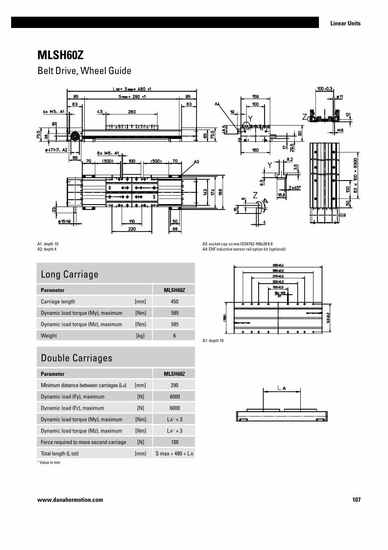
7/23/2019 Linear Actuator Danaher Motion
http://slidepdf.com/reader/full/linear-actuator-danaher-motion 107/224107
Linear Units
www.danahermotion.com
MLSH60Z
Belt Drive, Wheel Guide
Long CarriageParameter MLSH60Z
Carriage length [mm] 450
Dynamic load torque (My), maximum [Nm] 585
Dynamic load torque (Mz), maximum [Nm] 585
Weight [kg] 6
A1: depth 10
A2: depth 4
A3: socket cap screw ISO4762-M6x20 8.8
A4: ENF inductive sensor rail option kit (optional)
Double Carriages
Parameter MLSH60Z
Minimum distance between carriages (L A) [mm] 290
Dynamic load (Fy), maximum [N] 6000
Dynamic load (Fz), maximum [N] 6000
Dynamic load torque (My), maximum [Nm] L A 1 × 3
Dynamic load torque (Mz), maximum [Nm] L A 1 × 3
Force required to move second carriage [N] 100
Total length (L tot) [mm] S max + 480 + L A
A1: depth 10
1 Value in mm

7/23/2019 Linear Actuator Danaher Motion
http://slidepdf.com/reader/full/linear-actuator-danaher-motion 108/224108 www.danahermotion.com
MLSH80Z
Belt Drive, Wheel Guide
Performance Specifications
Parameter MLSH80Z
Stroke length (S max), maximum [mm] 5900
Linear speed, maximum [m/s] 10,0
Acceleration, maximum [m/s2] 40
Repeatability [± mm] 0,05
Input speed, maximum [rpm] 3000
Operation temperature limits [°C] 0 – 80
Dynamic load (Fx), maximum [N] 50003
Dynamic load (Fy), maximum [N] 50001 / 550902
Dynamic load (Fz), maximum [N] 50001 / 550902
Dynamic load torque (Mx), maximum [Nm] 3501 / 28902
Dynamic load torque (My), maximum [Nm] 4501 / 44902
Dynamic load torque (Mz), maximum [Nm] 4501 / 44902
Drive shaft force (Frd), maximum [N] 700
Drive shaft torque (Mta), maximum [Nm] 150
Pulley diameter [mm] 63,66
Stroke per shaft revolution [mm] 200
Weight
of unit with zero stroke of every 100 mm of stroke
of each carriage
[kg]
30,7 2,4
10,0
General Specifications
Parameter MLSH80Z
Profile size (w × h) [mm] 240 × 85
Type of belt 75ATL10
Carriage sealing system plastic cover band
Adjustable belt tensioning the belt can be retensioned
by the customer if necessary
Lubrication no lubrication required
Included accessories 4 × mounting clamps
Carriage Idle Torque, (M idle) [Nm]
Input speed [rpm] Idle torque [Nm]
150 8,5
1500 12,5
3000 15,5
M idle = the input torque needed to move the carriage with no load on it.
Force Fx as a Function of the Speed
Definition of Forces
1 Value for the complete unit2 Value for the wheel guide only3 See diagram Force Fx
Deflection of the Profile
A mounting clamp must be installed at least at every 750 mm to be able to operate the
maximum load. Less clamps may be required if less load is being operated, see the additional
technical data for more information.
» Ordering key - see page 215
» Accessories - see page 137
» Additional data - see page 193
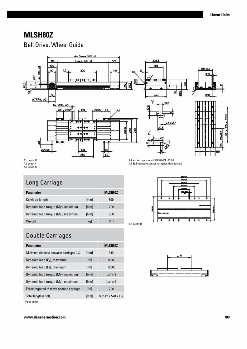
7/23/2019 Linear Actuator Danaher Motion
http://slidepdf.com/reader/full/linear-actuator-danaher-motion 109/224109
Linear Units
www.danahermotion.com
MLSH80Z
Belt Drive, Wheel Guide
Long Carriage
Parameter MLSH80Z
Carriage length [mm] 500
Dynamic load torque (My), maximum [Nm] 700
Dynamic load torque (Mz), maximum [Nm] 700
Weight [kg] 14,1
A1: depth 18
A2: depth 4
A3: depth 15
A4: socket cap screw ISO4762-M8×20 8.8
A5: ENF inductive sensor rail option kit (optional)
Double Carriages
Parameter MLSH80Z
Minimum distance between carriages (L A) [mm] 340
Dynamic load (Fy), maximum [N] 10000
Dynamic load (Fz), maximum [N] 10000
Dynamic load torque (My), maximum [Nm] L A 1 × 5
Dynamic load torque (Mz), maximum [Nm] L A 1 × 5
Force required to move second carriage [N] 200
Total length (L tot) [mm] S max + 570 + L A
A1: depth 15
1 Value in mm

7/23/2019 Linear Actuator Danaher Motion
http://slidepdf.com/reader/full/linear-actuator-danaher-motion 110/224110 www.danahermotion.com

7/23/2019 Linear Actuator Danaher Motion
http://slidepdf.com/reader/full/linear-actuator-danaher-motion 111/224111
Linear Units
www.danahermotion.com
Linear Lifting Units
SpeedLine, Movo Z
Typical Applications
Typical applications are found in most industries where light, medium or heavy loads
needs to be lifted. Examples are pick and place operations, materials handling,
electronic assembly and for lifting equipment in automotive assembly lines.
Developed for lifting applications
Models with ball
screw or belt drive
HighRepeatability
Stroke up to
3000 mm
Speed up to
10 m/s
Load up to750 kg
Telescopic modelsavailable
Large rangeof accessories
Load torque
up to 2000 Nm
Ball, slide orwheel guided models

7/23/2019 Linear Actuator Danaher Motion
http://slidepdf.com/reader/full/linear-actuator-danaher-motion 112/224112 www.danahermotion.com
Parameter WHZ50 WHZ80
Profile size (width × length) [mm] 50 × 50 80 × 80
Stroke length (S max), maximum [mm] 1500 3000
Linear speed, maximum [m/s] 6,5 10,0
Dynamic load (Fx), maximum [N] 670 1480
Remarks the load is always attached to the end of the
lifting profile
the load is always attached to the end of the
lifting profile
Page 114 116
Parameter Z2 Z3
Profile size (width × height) [mm] 188 × 150 188 × 150
Stroke length (S max), maximum [mm] 1500 1500
Linear speed, maximum [m/s] 1,25 1,25
Dynamic load (Fz), maximum [N] 7500 7500
Remarks Can be installed in any direction. The load must
be attached at the end of the lifting profile
Can only be installed vertically. The load must
be attached at the end of the lifting profile.
Page 118 120
Features
• Telescopic movement
• Ball screw drive
• Internal slide guides
• Load up to 7500 N
• Load torque up to 2000 Nm
• Two end stop limit switches (Z2 only)
Movo Z
SpeedLine WHZ Features
• Can be installed in all directions
• Belt drive
• External wheel guides
• Speed up to 10 m/s
• Acceleration up to 40 m/s2
WHZ50
Z2
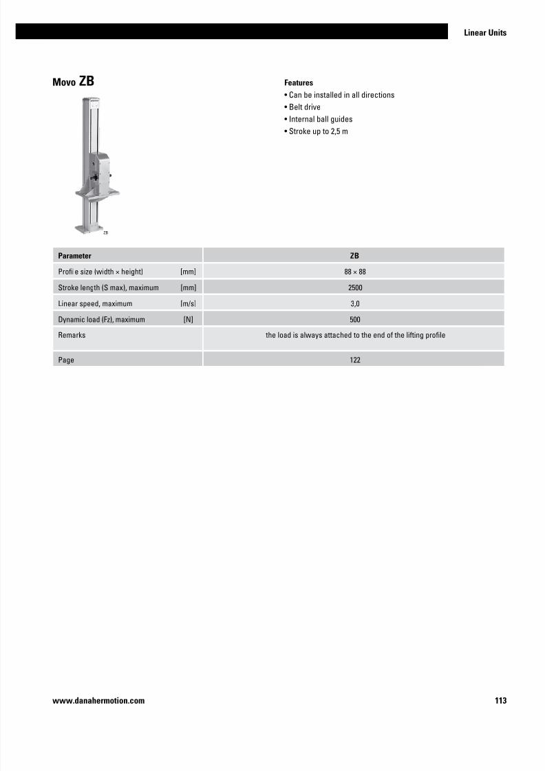
7/23/2019 Linear Actuator Danaher Motion
http://slidepdf.com/reader/full/linear-actuator-danaher-motion 113/224113
Linear Units
www.danahermotion.com
Features
• Can be installed in all directions
• Belt drive
• Internal ball guides
• Stroke up to 2,5 m
Parameter ZB
Profile size (width × height) [mm] 88 × 88
Stroke length (S max), maximum [mm] 2500
Linear speed, maximum [m/s] 3,0
Dynamic load (Fz), maximum [N] 500
Remarks the load is always attached to the end of the lifting profile
Page 122
Movo ZB
ZB

7/23/2019 Linear Actuator Danaher Motion
http://slidepdf.com/reader/full/linear-actuator-danaher-motion 114/224114 www.danahermotion.com
WHZ50
Belt Drive, Wheel Guide
Performance Specifications
Parameter WHZ50
Stroke length (S max), maximum [mm] 1500
Linear speed, maximum [m/s] 6,5
Acceleration, maximum [m/s2] 40
Repeatability [± mm] 0,05
Input speed, maximum [rpm] 3250
Operation temperature limits [°C] 0 – 80
Dynamic load (Fx), maximum [N] 6703
Dynamic load (Fy), maximum [N] 4151 / 28202
Dynamic load (Fz), maximum [N] 7301 / 50802
Dynamic load torque (Mx), maximum [Nm] 161 / 1002
Dynamic load torque (My), maximum [Nm] 871 / 5002
Dynamic load torque (Mz), maximum [Nm] 501 / 2802
Drive shaft force (Frd), maximum [N] 150
Drive shaft torque (Mta), maximum [Nm] 17
Pulley diameter [mm] 38,2
Stroke per shaft revolution [mm] 120
Weight
of unit with zero stroke of every 100 mm of stroke
of each drive station box
[kg]
4,500,42
2,90
General Specifications
Parameter WHZ50
Profile size (w × h) [mm] 50 × 50
Type of belt 16 ATL 5
Carriage sealing system none
Adjustable belt tensioning the belt can be retensioned
by the customer if necessary
Lubrication lubrication of carriage and guide
surfaces
Included accessories -
Carriage Idle Torque, (M idle) [Nm]
Input speed [rpm] Idle torque [Nm]
150 1,7
1500 2,4
3250 3,8
M idle = the input torque needed to move the carriage with no load on it.
Force Fx as a Function of the Speed
Definition of Forces
1 Value for the complete unit2 Value for the wheel guide only3 See diagram Force Fx
» Ordering key - see page 216
» Accessories - see page 137
» Additional data - see page 194

7/23/2019 Linear Actuator Danaher Motion
http://slidepdf.com/reader/full/linear-actuator-danaher-motion 115/224115
Linear Units
www.danahermotion.com
WHZ50
Belt Drive, Wheel Guide
Long Carriage
Parameter WHZ50
Carriage length [mm] 400
Dynamic load torque (My), maximum [Nm] 130
Dynamic load torque (Mz), maximum [Nm] 75
Weight [kg] 3,3
A1: depth 12A2: depth 3,5
A3: funnel type lubricating nipple DIN3405-M6×1-D1
A4: depth 16
Double Carriages2
Parameter WHZ50
Minimum distance between carriages (L A) [mm] 260
Dynamic load (Fy), maximum [N] 830
Dynamic load (Fz), maximum [N] 1460
Dynamic load torque (My), maximum [Nm] L A 1 × 0,415
Dynamic load torque (Mz), maximum [Nm] L A 1 × 0,73
Force required to move second carriage [N] 16
Total length (L tot) [mm] S max + 350 + L A
A5: depth 4A6: depth 8
A7: ENF inductive sensor rail option kit (optional)
1 Value in mm2 Second carriage is always a long carriage
A1: depth 12
A2: depth 3,5
A3: funnel type lubricating nipple DIN3405-M6×1-D1
A5: depth 4

7/23/2019 Linear Actuator Danaher Motion
http://slidepdf.com/reader/full/linear-actuator-danaher-motion 116/224116 www.danahermotion.com
WHZ80
Belt Drive, Wheel Guide
Performance Specifications
Parameter WHZ80
Stroke length (S max), maximum [mm] 3000
Linear speed, maximum [m/s] 10,0
Acceleration, maximum [m/s2] 40
Repeatability [± mm] 0,05
Input speed, maximum [rpm] 3000
Operation temperature limits [°C] 0 – 80
Dynamic load (Fx), maximum [N] 14803
Dynamic load (Fy), maximum [N] 8821 / 81602
Dynamic load (Fz), maximum [N] 21001 / 146802
Dynamic load torque (Mx), maximum [Nm] 751 / 4802
Dynamic load torque (My), maximum [Nm] 2301 / 16102
Dynamic load torque (Mz), maximum [Nm] 1001 / 9002
Drive shaft force (Frd), maximum [N] 500
Drive shaft torque (Mta), maximum [Nm] 50
Pulley diameter [mm] 63,66
Stroke per shaft revolution [mm] 200
Weight
of unit with zero stroke of every 100 mm of stroke
of each drive station box
[kg]
11,20 0,91
6,65
General Specifications
Parameter WHZ80
Profile size (w × h) [mm] 80 × 80
Type of belt 32 ATL 5
Carriage sealing system none
Adjustable belt tensioning the belt can be retensioned
by the customer if necessary
Lubrication lubrication of carriage and guide
surfaces
Included accessories -
Carriage Idle Torque, (M idle) [Nm]
Input speed [rpm] Idle torque [Nm]
150 2,4
1500 3,5
3000 5,0
M idle = the input torque needed to move the carriage with no load on it.
Force Fx as a Function of the Speed
Definition of Forces
1 Value for the complete unit2 Value for the wheel guide only3 See diagram Force Fx
» Ordering key - see page 216
» Accessories - see page 137
» Additional data - see page 194

7/23/2019 Linear Actuator Danaher Motion
http://slidepdf.com/reader/full/linear-actuator-danaher-motion 117/224117
Linear Units
www.danahermotion.com
WHZ80
Belt Drive, Wheel Guide
Long Carriage
Parameter WHZ80
Carriage length [mm] 450
Dynamic load torque (My), maximum [Nm] 345
Dynamic load torque (Mz), maximum [Nm] 150
Weight [kg] 7,4
A1: depth 20A2: depth 3,5
A3: funnel type lubricating nipple DIN3405-M6×1-D1
Double Carriages2
Parameter WHZ80
Minimum distance between carriages (L A) [mm] 300
Dynamic load (Fy), maximum [N] 1764
Dynamic load (Fz), maximum [N] 4200
Dynamic load torque (My), maximum [Nm] L A 1 × 0,882
Dynamic load torque (Mz), maximum [Nm] L A 1 × 2,1
Force required to move second carriage [N] 20
Total length (L tot) [mm] S max + 410 + L A
A4: depth 4A5: depth 15
A6: ENF inductive sensor rail option kit (optional)
1 Value in mm2 Second carriage is always a long carriage
A1: depth 20A2: depth 3,5
A3: funnel type lubricating nipple DIN3405-M6×1-D1A4: depth 4
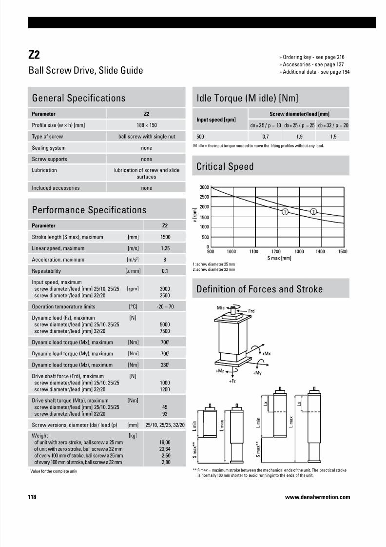
7/23/2019 Linear Actuator Danaher Motion
http://slidepdf.com/reader/full/linear-actuator-danaher-motion 118/224118 www.danahermotion.com
Performance Specifications
Parameter Z2
Stroke length (S max), maximum [mm] 1500
Linear speed, maximum [m/s] 1,25
Acceleration, maximum [m/s2] 8
Repeatability [± mm] 0,1Input speed, maximum
screw diameter/lead [mm] 25/10, 25/25
screw diameter/lead [mm] 32/20
[rpm] 3000
2500
Operation temperature limits [°C] -20 – 70
Dynamic load (Fz), maximum
screw diameter/lead [mm] 25/10, 25/25
screw diameter/lead [mm] 32/20
[N]
5000
7500
Dynamic load torque (Mx), maximum [Nm] 7001
Dynamic load torque (My), maximum [Nm] 7001
Dynamic load torque (Mz), maximum [Nm] 3301
Drive shaft force (Frd), maximum screw diameter/lead [mm] 25/10, 25/25
screw diameter/lead [mm] 32/20
[N]1000
1200
Drive shaft torque (Mta), maximum
screw diameter/lead [mm] 25/10, 25/25
screw diameter/lead [mm] 32/20
[Nm]
45
93
Screw versions, diameter (d0) / lead (p) [mm] 25/10, 25/25, 32/20
Weight
of unit with zero stroke, ball screw ø 25 mm
of unit with zero stroke, ball screw ø 32 mm
of every 100 mm of stroke, ball screw ø 25 mmof every 100 mm of stroke, ball screw ø 32 mm
[kg]
19,00
23,64
2,50 2,80
General Specifications
Parameter Z2
Profile size (w × h) [mm] 188 × 150
Type of screw ball screw with single nut
Sealing system none
Screw supports none
Lubrication lubrication of screw and slide
surfaces
Included accessories none
Definition of Forces and Stroke
Idle Torque (M idle) [Nm]
Input speed [rpm]Screw diameter/lead [mm]
d0 = 25 / p = 10 d0 = 25 / p = 25 d0 = 32 / p = 20
500 0,7 1,9 1,5
M idle = the input torque needed to move the lifting profiles without any load.
Critical Speed
Z2
Ball Screw Drive, Slide Guide
1: screw diameter 25 mm
2: screw diameter 32 mm
** S max = maximum stroke between the mechanical ends of the unit. The practical stroke is normally 100 mm shorter to avoid running into the ends of the unit.
1 Value for the complete uniy
» Ordering key - see page 216
» Accessories - see page 137
» Additional data - see page 194

7/23/2019 Linear Actuator Danaher Motion
http://slidepdf.com/reader/full/linear-actuator-danaher-motion 119/224119
Linear Units
www.danahermotion.com
A1: depth 12, Heli coil
A2: T-slot
Type of unit Minimum retracted length (L min) [mm] Maximum extended length (L max) [mm]
Standard L min = S max + 380 L max = L min + S maxElongated* L min = S max + 380 + Lx L max = L min + S max
Z2
Ball Screw Drive, Slide Guide
* Elongated versions have an extra length (Lx) added to the total length of the unit which makes the unit longer but does not add any extra length to the stroke (S max).
A1: depth 9, Heli coilA2: T-slot
MGZ2K25screw ø25 mm
MGZ2K32
screw ø32 mm

7/23/2019 Linear Actuator Danaher Motion
http://slidepdf.com/reader/full/linear-actuator-danaher-motion 120/224120 www.danahermotion.com
Performance Specifications
Parameter Z3
Stroke length (S max), maximum [mm] 1500
Linear speed, maximum [m/s] 1,25
Acceleration, maximum [m/s2] 8
Repeatability [± mm] 0,1Input speed, maximum
screw diameter/lead [mm] 25/10, 25/25
screw diameter/lead [mm] 32/20
[rpm] 3000
2500
Operation temperature limits [°C] -20 – 70
Dynamic load (Fz), maximum
screw diameter/lead [mm] 25/10, 25/25
screw diameter/lead [mm] 32/20
[N]
5000
7500
Dynamic load torque (Mx), maximum [Nm] 20001
Dynamic load torque (My), maximum [Nm] 20001
Dynamic load torque (Mz), maximum [Nm] 3301
Drive shaft force (Frd), maximum screw diameter/lead [mm] 25/10, 25/25
screw diameter/lead [mm] 32/20
[N]1000
1200
Drive shaft torque (Mta), maximum
screw diameter/lead [mm] 25/10, 25/25
screw diameter/lead [mm] 32/20
[Nm]
45
93
Screw versions, diameter (d0) / lead (p) [mm] 25/10, 25/25, 32/20
Weight
of unit with zero stroke, ball screw ø 25 mm
of unit with zero stroke, ball screw ø 32 mm
of every 100 mm of stroke, ball screw ø 25 mmof every 100 mm of stroke, ball screw ø 32 mm
[kg]
21,14
22,65
4,20 4,50
General Specifications
Parameter Z3
Profile size (w × h) [mm] 188 × 150
Type of screw ball screw with single nut
Sealing system none
Screw supports none
Lubrication lubrication of screw and slide
surfaces
Included accessories none
Idle Torque (M idle) [Nm]
Input speed [rpm]Screw diameter/lead [mm]
d0 = 25 / p = 10 d0 = 25 / p = 25 d0 = 32 / p = 20
500 1,1 2,7 2,2
M idle = the input torque needed to move the lifting profiles without any load.
Critical Speed
Z3
Ball Screw Drive, Slide Guide
1: screw diameter 25 mm
2: screw diameter 32 mm
Definition of Forces and Stroke
** S max = maximum stroke between the mechanical ends of the unit. The practical stroke is normally 100 mm shorter to avoid running into the ends of the unit.
1 Value for the complete uniy
» Ordering key - see page 216
» Accessories - see page 137
» Additional data - see page 194

7/23/2019 Linear Actuator Danaher Motion
http://slidepdf.com/reader/full/linear-actuator-danaher-motion 121/224121
Linear Units
www.danahermotion.com
Type of unit Minimum retracted length (L min) [mm] Maximum extended length (L max) [mm]
Standard L min = S max + 170 L max = L min + S max
Elongated* L min = S max + 170 + Lx L max = L min + S max
Z3
Ball Screw Drive, Slide Guide
* Elongated versions have an extra length (Lx) added to the total length of the unit which makes the unit longer but does not add any extra length to the stroke (S max).
A1: depth 12, Heli coil
A2: T-slot
A1: depth 9, Heli coilA2: T-slot
MGZ3K25screw ø25 mm
MGZ3K32
screw ø32 mm

7/23/2019 Linear Actuator Danaher Motion
http://slidepdf.com/reader/full/linear-actuator-danaher-motion 122/224122 www.danahermotion.com
ZB
Belt Drive, Ball Guide
Performance Specifications
Parameter ZB
Stroke length (S max), maximum [mm] 2500
Linear speed, maximum [m/s] 3,0
Acceleration, maximum [m/s2] 40
Repeatability [± mm] 0,1
Input speed, maximum [rpm] 900
Operation temperature limits [°C] -20 – 70
Dynamic load (Fz), maximum [N] 500
Dynamic load torque (Mx), maximum [Nm] 4451 / 33402
Dynamic load torque (My), maximum [Nm] 4451 / 33402
Dynamic load torque (Mz), maximum [Nm] 351 / 2622
Drive shaft force (Frd), maximum [N] 600
Drive shaft torque (Mta), maximum [Nm] 34
Pulley diameter [mm] 63,66
Stroke per shaft revolution [mm] 200
Weight
of unit with zero stroke
of every 100 mm of stroke
of the drive station box
[kg]15,50
0,86
16,20
General Specifications
Parameter ZB
Profile size (w × h) [mm] 88 × 88
Type of belt 50 AT 10
Carriage sealing system none
Adjustable belt tensioning the belt can be retensioned
by the customer if necessary
Lubrication lubrication of drive station in two
points
Included accessories none
Idle Torque, (M idle) [Nm]
Input speed [rpm] Idle torque [Nm]
500 6,4
M idle = the input torque needed to move the lifting profile with no load on it.
Definition of Forces
1 Value for the complete unit2 Value for the ball guide only
» Ordering key - see page 217
» Accessories - see page 137
» Additional data - see page 194

7/23/2019 Linear Actuator Danaher Motion
http://slidepdf.com/reader/full/linear-actuator-danaher-motion 123/224123
Linear Units
www.danahermotion.com
ZB
Belt Drive, Ball Guide
A1: depth 17A2: depth 20

7/23/2019 Linear Actuator Danaher Motion
http://slidepdf.com/reader/full/linear-actuator-danaher-motion 124/224124 www.danahermotion.com

7/23/2019 Linear Actuator Danaher Motion
http://slidepdf.com/reader/full/linear-actuator-danaher-motion 125/224

7/23/2019 Linear Actuator Danaher Motion
http://slidepdf.com/reader/full/linear-actuator-danaher-motion 126/224126 www.danahermotion.com
Parameter WZ60 WZ80
Profile size (width × height) [mm] 60 × 60 80 × 80
Stroke length (S max), maximum [mm] 400 500
Linear speed, maximum [m/s] 1,5 1,5
Dynamic carriage load (Fx), maximum [N] 2800 3500
Remarks
Page 128 130
Features
• Can be installed in all directions
• Ball screw drive
• Ball guides
• Compact
VarioLine WZ
WZ60

7/23/2019 Linear Actuator Danaher Motion
http://slidepdf.com/reader/full/linear-actuator-danaher-motion 127/224127
Linear Units
www.danahermotion.com
Parameter T90 T130
Profile size (width × height) [mm] 90 × 92 130 × 130
Stroke length (S max), maximum [mm] 1500 2000
Linear speed, maximum [m/s] 2,0 2,0
Dynamic carriage load (Fx), maximum [N] 20000 40000
Remarks mounting accessories according to hydrauliccylinder standards available
mounting accessories according to hydrauliccylinder standards available
Page 132 134
Features
• Can be installed in all directions
• Ball screw drive
• Slide guides
• Load up to 40000 N
• IP65 protection class
• Wash down protected versions available
Movotrak T
T90

7/23/2019 Linear Actuator Danaher Motion
http://slidepdf.com/reader/full/linear-actuator-danaher-motion 128/224128 www.danahermotion.com
WZ60
Ball Screw Drive, Ball Guide
Performance Specifications
Parameter WZ60
Stroke length (S max), maximum [mm] 400
Linear speed, maximum [m/s] 1,5
Acceleration, maximum [m/s2] 20
Repeatability [± mm] 0,02
Input speed, maximum [rpm] 3000
Operation temperature limits [°C] 0 – 80
Dynamic load (Fx), maximum [N] 28001
Dynamic load (Fy), maximum [N] 20002
Dynamic load (Fz), maximum [N] 20002
Dynamic load torque (Mx), maximum [Nm] 501
Drive shaft force (Frd), maximum [N] 500
Drive shaft torque (Mta), maximum [Nm] 30
Ball screw diameter (d0) [mm] 20
Ball screw lead (p) [mm] 5, 20, 50
Weight
of unit with zero stroke
of every 100 mm of stroke of the rod with zero stroke
of every 100 mm of rod
[kg]
4,5
0,771,8
0,26
General Specifications
Parameter WZ60
Profile size (w × h) [mm] 60 × 60
Type of screw single nut ball screw
Lubrication central lubrication of all parts that
require lubrication
Included accessories 4 × mounting clamps
Rod Idle Torque (M idle) [Nm]
Input speed [rpm]Screw lead [mm]
p = 5 p = 20 p = 50
150 0,7 1,0 1,4
1500 1,1 1,6 2,0
3000 1,5 1,8 2,2
M idle = the input torque needed to move the rod with no load on it.
1 Value for the complete unit2 See diagram Maximum Rod Side Forces (Fy, Fz)
Definition of Forces
» Ordering key - see page 218
» Accessories - see page 137
» Additional data - see page 195

7/23/2019 Linear Actuator Danaher Motion
http://slidepdf.com/reader/full/linear-actuator-danaher-motion 129/224129
Linear Units
www.danahermotion.com
WZ60
Ball Screw Drive, Ball Guide
Maximum Rod Side Forces (Fy, Fz)
A1: depth 13
A2: locking plug for lubricating nippleA3: socket cap screw ISO4762-M6×20 8.8
A4: tapered lubricating nipple to DIN71412 AM6 as standard feature
Deflection (f) of Rod due to Fy and Fz
Torsion (j) of Rod due to Mx
1: Load = 2000 N
2: Load = 1500 N
3: Load = 1000 N4: Load = 500 N
5: Load = 250 N
6: Load = 125 N
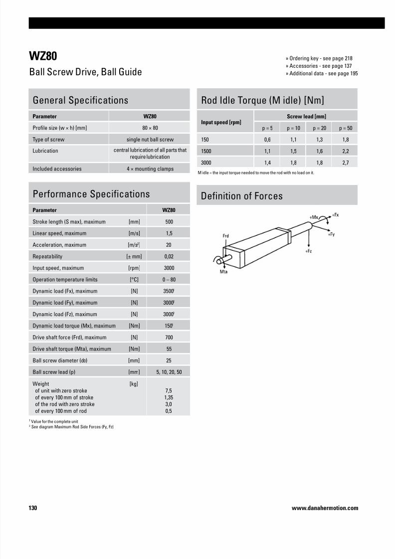
7/23/2019 Linear Actuator Danaher Motion
http://slidepdf.com/reader/full/linear-actuator-danaher-motion 130/224130 www.danahermotion.com
WZ80
Ball Screw Drive, Ball Guide
Performance Specifications
Parameter WZ80
Stroke length (S max), maximum [mm] 500
Linear speed, maximum [m/s] 1,5
Acceleration, maximum [m/s2] 20
Repeatability [± mm] 0,02
Input speed, maximum [rpm] 3000
Operation temperature limits [°C] 0 – 80
Dynamic load (Fx), maximum [N] 35001
Dynamic load (Fy), maximum [N] 30002
Dynamic load (Fz), maximum [N] 30002
Dynamic load torque (Mx), maximum [Nm] 1501
Drive shaft force (Frd), maximum [N] 700
Drive shaft torque (Mta), maximum [Nm] 55
Ball screw diameter (d0) [mm] 25
Ball screw lead (p) [mm] 5, 10, 20, 50
Weight
of unit with zero stroke
of every 100 mm of stroke of the rod with zero stroke
of every 100 mm of rod
[kg]
7,5
1,353,0
0,5
General Specifications
Parameter WZ80
Profile size (w × h) [mm] 80 × 80
Type of screw single nut ball screw
Lubrication central lubrication of all parts that
require lubrication
Included accessories 4 × mounting clamps
Rod Idle Torque (M idle) [Nm]
Input speed [rpm]Screw lead [mm]
p = 5 p = 10 p = 20 p = 50
150 0,6 1,1 1,3 1,8
1500 1,1 1,5 1,6 2,2
3000 1,4 1,8 1,8 2,7
M idle = the input torque needed to move the rod with no load on it.
1 Value for the complete unit2 See diagram Maximum Rod Side Forces (Fy, Fz)
Definition of Forces
» Ordering key - see page 218
» Accessories - see page 137
» Additional data - see page 195

7/23/2019 Linear Actuator Danaher Motion
http://slidepdf.com/reader/full/linear-actuator-danaher-motion 131/224131
Linear Units
www.danahermotion.com
WZ80
Ball Screw Drive, Ball Guide
Maximum Rod Side Forces (Fy, Fz)
A1: depth 13
A2: locking plug for lubricating nippleA3: socket cap screw ISO4762-M6×20 8.8
A4: tapered lubricating nipple to DIN71412 AM6 as standard feature
Deflection (f) of Rod due to Fy and Fz
Torsion (j) of Rod due to Mx
1: Load = 3000 N
2: Load = 2500 N
3: Load = 2000 N4: Load = 1500 N
5: Load = 1000 N6: Load = 500 N
7: Load = 250 N
8: Load = 125 N

7/23/2019 Linear Actuator Danaher Motion
http://slidepdf.com/reader/full/linear-actuator-danaher-motion 132/224132 www.danahermotion.com
T90
Ball Screw Drive, Slide Guide
General Specifications
Parameter T90
Profile size (w × h) [mm] 90 × 92
Type of screw ball screw with single nut
Protection class IP65
Lubrication One point lubrication of ballscrew
Included accessories –
Definition of Forces
Rod Idle Torque (M idle) [Nm]
Input speed [rpm]Screw lead [mm]
p = 5 p = 10 p = 20 p = 25 p = 32
500 1,5 1,5 3,0 2,0 3,5
M idle = the input torque needed to move the rod with no load on it.
Performance Specifications
Parameter T90
Stroke length (S max), maximum [mm] 1500
Linear speed, maximum [m/s] 2,0
Acceleration, maximum [m/s2] 8
Repeatability [± mm] 0,05
Input speed, maximum screw diameter/lead 25/05 mm
screw diameter/lead 25/10, 25/25 mm
screw diameter/lead 32/20, 32/32 mm
[rpm] 4000
4800
3750
Operation temperature limits [°C] -20 – 70
Dynamic load (Fx), maximum
screw diameter 25 mm
screw diameter 32 mm
[N]
10000
20000
Dynamic load (Fy), maximum
screw diameter 25 mm
screw diameter 32 mm
[N]
3001
5001
Dynamic load (Fz), maximum screw diameter 25 mm
screw diameter 32 mm
[N] 3001
5001
Dynamic load torque (Mz, My), maximum [Nm] 1501
Drive shaft force (Frd), maximum
screw diameter 25 mm screw diameter 32 mm
[N]
10001300
Drive shaft torque (Mta), maximum
screw diameter 25 mm
screw diameter 32 mm
[Nm]
48
93
Performance Specifications
Parameter T90
Screw versions, diameter (d0) / lead (p) [mm] 25/05, 25/10, 25/2532/20, 32/32
Weight of unitswith screw diameter 25 mm
of unit with zero stroke
of every 100 mm of stroke
of the rod with zero stroke
of every 100 mm of rod
[kg]
8,16
1,62
0,52
0,60
Weight of units
with screw diameter 32 mm
of unit with zero stroke of every 100 mm of stroke
of the rod with zero stroke
of every 100 mm of rod
[kg]
10,64 1,80
0,55
0,60
1 Value for the complete unit
» Ordering key - see page 218
» Accessories - see page 137
» Additional data - see page 195

7/23/2019 Linear Actuator Danaher Motion
http://slidepdf.com/reader/full/linear-actuator-danaher-motion 133/224133
Linear Units
www.danahermotion.com
T90
Ball Screw Drive, Slide Guide
A1: depth 18A2: depth 33
A3: outside thread
T09-B25screw ø25 mm
T09-B32
screw ø32 mm
A1: depth 18
A2: depth 43A3: outside thread
A4: inside threadA5: T-slot
A4: inside thread
A5: T-slot

7/23/2019 Linear Actuator Danaher Motion
http://slidepdf.com/reader/full/linear-actuator-danaher-motion 134/224134 www.danahermotion.com
T130
Ball Screw Drive, Slide Guide
General Specifications
Parameter T130
Profile size (w × h) [mm] 130 × 130
Type of screw ball screw with single nut
Protection class IP65
Lubrication One point lubrication of ballscrew
Included accessories –
Definition of Forces
Rod Idle Torque (M idle) [Nm]
Input speed [rpm]Screw lead [mm]
p = 10 p = 20 p = 40
500 4,5 4,5 5,5
M idle = the input torque needed to move the rod with no load on it.
Performance Specifications
Parameter T130
Stroke length (S max), maximum [mm] 2000
Linear speed, maximum [m/s] 2,0
Acceleration, maximum [m/s2] 8
Repeatability [± mm] 0,05
Input speed, maximumscrew lead 10 mm
screw lead 20, 40 mm
[rpm] 2500
3000
Operation temperature limits [°C] - 20 – 70
Dynamic load (Fx), maximum
screw lead 10 mm
screw lead 20 mm
screw lead 40 mm
[N]40000
35000
15000
Dynamic load (Fy), maximum [N] 8001
Dynamic load (Fz), maximum [N] 8001
Dynamic load torque (My, Mz), maximum [Nm] 3001
Drive shaft force (Frd), maximum [N] 3000
Drive shaft torque (Mta), maximum [Nm] 140
Ball screw diameter (p) [mm] 40
Ball screw leads (d0) [mm] 10, 20, 40
Weight
of unit with zero stroke
of every 100 mm of stroke
of the rod with zero stroke of every 100 mm of rod
[kg]
18,50
3,00
1,25 0,77
1 Value for the complete unit
» Ordering key - see page 218
» Accessories - see page 137
» Additional data - see page 195

7/23/2019 Linear Actuator Danaher Motion
http://slidepdf.com/reader/full/linear-actuator-danaher-motion 135/224135
Linear Units
www.danahermotion.com
T130
Ball Screw Drive, Slide Guide
A1: depth 28A2: depth 20
A3: outside thread
A4: inside threadA5: T-slot

7/23/2019 Linear Actuator Danaher Motion
http://slidepdf.com/reader/full/linear-actuator-danaher-motion 136/224136 www.danahermotion.com

7/23/2019 Linear Actuator Danaher Motion
http://slidepdf.com/reader/full/linear-actuator-danaher-motion 137/224137
Linear Units
www.danahermotion.com
Accessories
Accessory index
Electrical Feedback Devices.............................................................................page 172
Mounting Kits.............................................................................................page 137
Motors, Gears and Transmission Kits...............................................................page 147
Non Driven Units..................................................................................................page 182
Dynamic Servo Actuators..................................................................................page 188
• Felt pad wipers type FA .....................................144
• Bellows, shrouds and shaft covers .................145
• Environment protection type S1 and S2 ..........146
• Limit switch brackets and limit switches .............................. 172 • Limit switch kits type ES ...................................................176
• Inductive and magnetic sensors and sensor brackets .......173 • Sensor rails and kits type ENT, ENF and ENK ................178
• Encoders ...................................................................................175 • Encoder kits type ADG ......................................................180
• WH series non driven units................................ 182
• WM series non driven units............................... 184
• M series non driven units .................................. 187
• Presentation of Dynamic Servo Actuators ...... 188
Cover and Protection Kits.........................................................................page 144
Multi Axis System Kits........................................................................................page 189
• Presentation of multi axis system kits ................. 189
• Mounting clamps ..................................................................... 138 • T90/T130 mounting kits ......................................................143
• Mounting clamps for multi axis systems .............................. 140
• Adapter plates .......................................................................... 141
• T-slot bolts and nuts................................................................. 142
• Bell house flanges for IEC motors .........................................147 • Bevel gears type KRG ........................................................ 158
• Bell house flanges type MGK .................................................148 • Planetary gears type Micron DT and DTR ...................... 164
• Worm gears type BS and TBS ................................................150 • Intermediate shafts type VWZ and DSP.......................... 166
• Belt gears type RT and BGM ..................................................154 • Servo motors type AKM and DLB .................................... 170
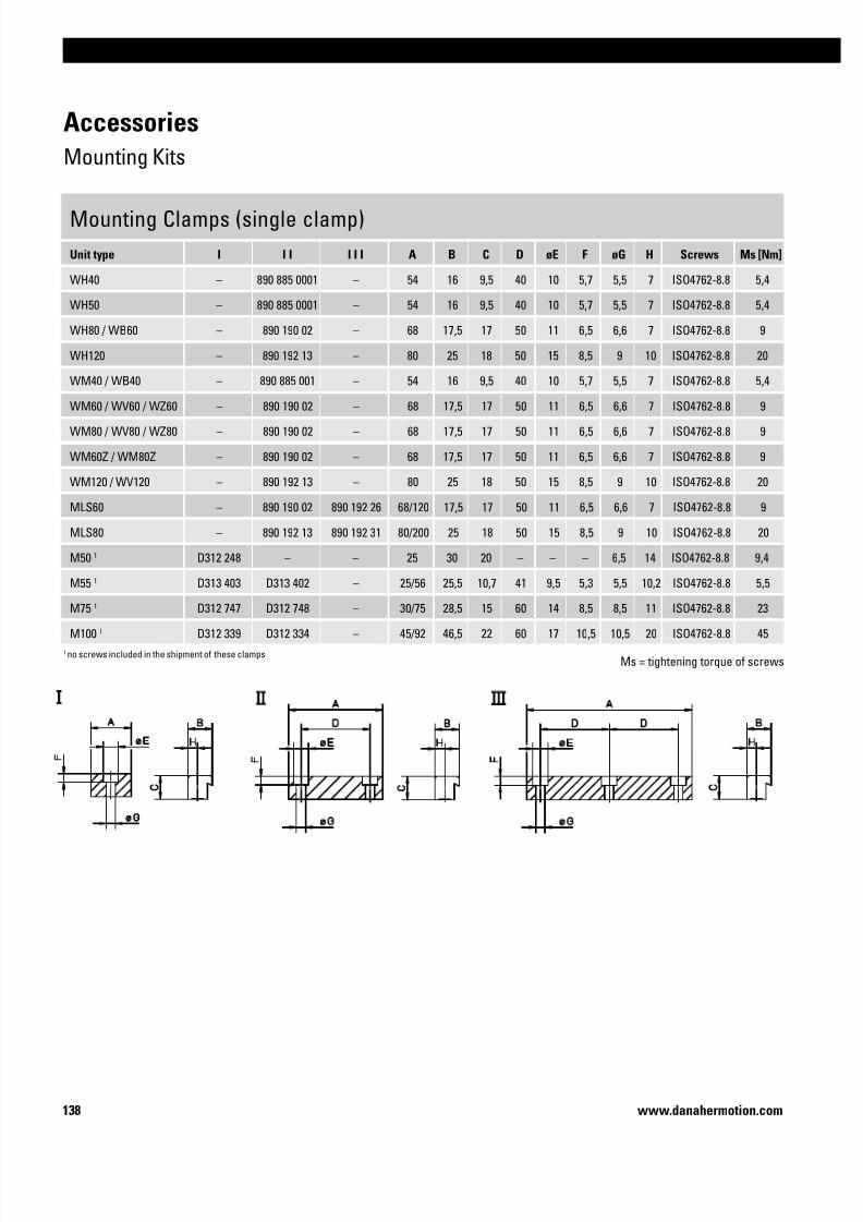
7/23/2019 Linear Actuator Danaher Motion
http://slidepdf.com/reader/full/linear-actuator-danaher-motion 138/224138 www.danahermotion.com
Accessories
Mounting Kits
Mounting Clamps (single clamp)
Unit type I I I I I I A B C D øE F øG H Screws Ms [Nm]
WH40 – 890 885 0001 – 54 16 9,5 40 10 5,7 5,5 7 ISO4762-8.8 5,4
WH50 – 890 885 0001 – 54 16 9,5 40 10 5,7 5,5 7 ISO4762-8.8 5,4
WH80 / WB60 – 890 190 02 – 68 17,5 17 50 11 6,5 6,6 7 ISO4762-8.8 9
WH120 – 890 192 13 – 80 25 18 50 15 8,5 9 10 ISO4762-8.8 20
WM40 / WB40 – 890 885 001 – 54 16 9,5 40 10 5,7 5,5 7 ISO4762-8.8 5,4
WM60 / WV60 / WZ60 – 890 190 02 – 68 17,5 17 50 11 6,5 6,6 7 ISO4762-8.8 9
WM80 / WV80 / WZ80 – 890 190 02 – 68 17,5 17 50 11 6,5 6,6 7 ISO4762-8.8 9
WM60Z / WM80Z – 890 190 02 – 68 17,5 17 50 11 6,5 6,6 7 ISO4762-8.8 9
WM120 / WV120 – 890 192 13 – 80 25 18 50 15 8,5 9 10 ISO4762-8.8 20
MLS60 – 890 190 02 890 192 26 68/120 17,5 17 50 11 6,5 6,6 7 ISO4762-8.8 9
MLS80 – 890 192 13 890 192 31 80/200 25 18 50 15 8,5 9 10 ISO4762-8.8 20
M50 1 D312 248 – – 25 30 20 – – – 6,5 14 ISO4762-8.8 9,4
M55 1 D313 403 D313 402 – 25/56 25,5 10,7 41 9,5 5,3 5,5 10,2 ISO4762-8.8 5,5
M751
D312 747 D312 748 – 30/75 28,5 15 60 14 8,5 8,5 11 ISO4762-8.8 23
M100 1 D312 339 D312 334 – 45/92 46,5 22 60 17 10,5 10,5 20 ISO4762-8.8 45
1 no screws included in the shipment of these clampsMs = tightening torque of screws

7/23/2019 Linear Actuator Danaher Motion
http://slidepdf.com/reader/full/linear-actuator-danaher-motion 139/224139
Linear Units
www.danahermotion.com
Mounting Clamps with Plate1
Unit type p/n A B C D E øF øG H
M50 D312 117 7 20 105 35 30 6,5 11 –
M55 D313 474 8,5 15 100 44 70 8,5 14 44
M75 D312 718 8,5 15 134 44 80 8,5 14 44
M100 D312 317 8,5 20 190 44 100 8,5 14 44
1 two mounting clamps of version II (see page 138) and screws to connect these to the plate are included in shipment
Accessories
Mounting Kits

7/23/2019 Linear Actuator Danaher Motion
http://slidepdf.com/reader/full/linear-actuator-danaher-motion 140/224140 www.danahermotion.com
Accessories
Mounting Kits
Mounting Clamps for Multi Axis Systems1
Unit type X-axis Unit type Y-axis I I I A B C D øE F øG H
WM40 / WH40 WM40 / WH40 on request – – – – – – – – –
WM60 WM60 890 191 94 – 58 17,5 17 40 11 6,5 6,6 7
M55 M55 D313 424 – 56 25,5 10,7 41 9,5 5,3 5,5 10,2
M55 M75 – D313 470 5,5 15 134 76 80 5,5 9,5 41
M75 M55 – D313 060 - 15 134 76 80 M5 × 7,5 - 41
M75 M75 D312 719 – 75 28,5 15 60 14 8,5 8,5 11
M75 M100 – D313 062 8,5 20 190 106 100 8,5 14 60
M100 M75 – D313 292 - 20 190 106,5 100 M8 × 12 - 60
M100 M100 D312 304 – 92 46,5 22 60 17 10,5 10,5 201 all necessary screws are included in the shipment

7/23/2019 Linear Actuator Danaher Motion
http://slidepdf.com/reader/full/linear-actuator-danaher-motion 141/224141
Linear Units
www.danahermotion.com
Accessories
Mounting Kits
Adapter Plates
Unit type I I I A B C D E øF G
M55 D313 422 D313 423 40 60 20 38 25,5 6,5 37
M75 D312 746 – 40 – 26 - 45 6,5 51
M75 – D312 745 – 60 - 39 45 7,5 51
M100 D312 338 – 40 – 26 - 69 6,5 62
M100 – D312 337 – 60 - 39 69 7,5 62
Adapter plates are fitted in the grooves along
the profile and can be used to attach objects like
sensors, swithes, cable ducts etc. to the unit.

7/23/2019 Linear Actuator Danaher Motion
http://slidepdf.com/reader/full/linear-actuator-danaher-motion 142/224142 www.danahermotion.com
Accessories
Mounting Kits
T-slot Bolts
Unit type p/n øD H
M50 D312 221 M5 14
T90 D310 314 M6 18
T90 D310 311 M6 26
T130 D310 314 M6 18
T130 D310 311 M6 26
Z2 D800 089 M10 28
Z3 D800 089 M10 28
T-slot Nuts
Unit type p/n A B C D øE F
2HBE10 D16965-A-01 7 4 1,75 3 M3 9
2HBE10 D16965-A-02-M4 9,5 5,5 2,25 4 M4 12
2HBE20 D16965-A-01 7 4 1,75 3 M3 9
2HBE20 D18063-A-04-M6 16,5 7,9 4,5 6 M6 7,9
ZB D900 151 18 11 1,5 6,3 M6 25
ZB D900 150 18 11 1,5 6,3 M8 25
MLS60 920 303 0037 16 8 4 6 M6 16
MLS80 920 303 0039 19,5 10 5,5 10,5 M8 20
WH120 911 044 19 15 10 6 12 M8 15
WM120 911 044 19 15 10 6 12 M8 15

7/23/2019 Linear Actuator Danaher Motion
http://slidepdf.com/reader/full/linear-actuator-danaher-motion 143/224143
Linear Units
www.danahermotion.com
Accessories
Mounting Kits
Mounting Feet Kit (pair)
Unit type p/n A B C D E F G
T90 (T09-B25) D606 225 40 155 20 125 15 ø13 141
T90 (T09-B32) D606 225 40 155 20 125 15 ø13 162
T130 D606 157 60 220 30 176 22 ø17 216
The mounting feet includes all
neccessary screws to attach the
feet to the unit.
A1: T90 tightening torque = 78 Nm
T130 tightening torque = 220 Nm
Trunnion Mounting Kit (pair)
Unit type p/n A B C øD E F G H
T90 D606 030 150 45 240 20 f8 25 75 130 80
T130 D606 155 210 53 316 35 f8 30 93 180 110

7/23/2019 Linear Actuator Danaher Motion
http://slidepdf.com/reader/full/linear-actuator-danaher-motion 144/224144 www.danahermotion.com
Accessories
Cover and Protection Kits
FA Felt Pad Wiper
Unit type Number of carriages on the unit p/n X
WH50 1 890 885 0064 6
WH50 2 2 × 890 885 0064 6
WH80 1 890 890 0069 7
WH80 2 2 × 890 890 0069 7
WH120 1 890 895 0058 8
WH120 2 2 × 890 895 0058 8
WHZ50 1 890 885 0064 6
WHZ50 2 2 × 890 885 0064 6
WHZ80 1 890 890 0069 7
WHZ80 2 2 × 890 890 0069 7
The felt pad wipers remove dust and dirt from the guides and are located
on the carriage(s). They may increase the driving torque slightly but does
not reduce the stroke of the unit. The felt pad wipers comes mounted
from factory.

7/23/2019 Linear Actuator Danaher Motion
http://slidepdf.com/reader/full/linear-actuator-danaher-motion 145/224145
Linear Units
www.danahermotion.com
Accessories
Cover and Protection Kits
Protective Bellows
Unit type p/n B B2 H H1 H2 H4
2HBE10 BEL-2H-10 103 81 26 11 10 0
2HBE20 BEL-2H-20 199 167 48 30 15 5
The protective bellows protect the entire unit from dust
and dirt. Bellows option reduces the available stroke of
the unit by about 28 %. Bellows can be ordered mounted
from factory and in that case this is stated in the ordering
key of the unit. It can also be ordered separately to befitted by the customer. In this case the part number and
the length of the bellows must be stated. For 2HBE10 the
correct bellows length is max. stroke of the unit (Smax) +
100 while it for 2HBE20 is the max. stroke (Smax) + 200.
Protective Shrouds
Unit type
2HBE10 see ordering key of the unit for order
2HBE20 see ordering key of the unit for order
The protective shrouds are made of metal and protect
the drive mechanism of the unit from dust and dirt but
leaves the guides unprotected. Shrouds do not reduce
the stroke of the unit but they will add 4 mm to the width
of the unit. Shrouds are ordered mounted from factory
and is stated in the ordering key of the unit.
Shaft Protection Cover
Unit type p/n A B
M50 D312 201 126 35
M55 D312 201 151 35
M75 D700 178 198 45
M100 D700 178 202 45
The shaft protection cover is used to cover shafts which is not being
used. The cover is fitted by the customer.

7/23/2019 Linear Actuator Danaher Motion
http://slidepdf.com/reader/full/linear-actuator-danaher-motion 146/224146 www.danahermotion.com
Accessories
Cover and Protection Kits
Environment Protection Option Type S1 and S2, compatability table
Unit type Drive type Guide type S1 S2 Ordering
M55 ball screw slide • see ordering key of the unit for order
M55 belt driveslide • • see ordering key of the unit for order
ball • see ordering key of the unit for order
M75 ball screw slide • see ordering key of the unit for order
M75 belt driveslide • • see ordering key of the unit for order
ball • see ordering key of the unit for order
M100 ball screw slide • see ordering key of the unit for order
M100 belt driveslide • • see ordering key of the unit for order
ball • see ordering key of the unit for order
The S1 and S2 environment protection option can be ordered to some
units. All performance data and the life expectancy is the same as for
standard units. S1 can be ordered for both ball screw and belt driven
units with ball or slide guides while S2 only is possible for belt driven
slide guided units.
S1 - Wash down protection
Typical places where S1 is used are in slaughter houses, dairy plants,
food plants or in any other light wash down application.
S2 - Chemical protection
Typical applications where S2 is used are in wet areas in paper mills,
galvanising equipment, chemical industry equipment or in any other
application where water, acid and/or basic liquids are present.
Environment Protection Option Type S1 and S2, technical specification
Item S1 S2
External screws, bolts and nuts stainless material class A2 or better stainless material class A4 or better
Internal screws, bolts and nuts standard material stainless material class A2 or better
Drive shaft, ball screw driven units standard material -
Drive shaft, belt driven units stainless material SS2333 or better stainless material SS2343 or better
Tension wheel shaft standard material stainless material SS2333 or better
Bearings type standard bearings 2RS
Bearing sealings, belt driven units radial sealings radial sealings
Surface treatment of machined extruded aluminum parts none anodising
Surface treatment of machined casted aluminum parts none anodising

7/23/2019 Linear Actuator Danaher Motion
http://slidepdf.com/reader/full/linear-actuator-danaher-motion 147/224147
Linear Units
www.danahermotion.com
Accessories
Motors, Gears and Transmission Kits
Bell House Flanges for IEC Motors
Unit type IEC63 B14 A IEC71 B14 A IEC80 B14 A IEC90 B14 A IEC100/112 B14 A
M50 D390 820 64 D390 821 71 – – – – – –
M55 D390 820 64 D390 821 71 – – – – – –
M75 – – D390 823 83 D390 912 1O1 D390 916 101 – –
M100 (MG10K) – – D390 823 83 D390 913 1O1 D390 917 101 – –
M100 (MG10B) – – D390 823 83 D390 912 1O1 D390 916 101 – –
T90 (T09-B25) – – D390 823 83 D390 914 1O1 D390 918 101 – –
T90 (T09-B32) – – – – D390 922 1O1 D390 924 108 – –
T130 – – – – – – D606 180 115 D606 181 125
The bell house flange includes a matching
coupling. Note! Keep in mind that heavy
motors will need extra support in order not
to break the flange or gear due to the load
torque created.

7/23/2019 Linear Actuator Danaher Motion
http://slidepdf.com/reader/full/linear-actuator-danaher-motion 148/224148 www.danahermotion.com
Accessories
Motors, Gears and Transmission Kits
MGK Bell House Flanges for AKM Servo Motors
Unit type AKM3 • D-AN A AKM4 • D-AN A AKM5 • D-AN A AKM6 • D-AN A AKM7 • D-AN A
WM40 891 092 1264 71 – – – – – – – –
WB40 891 092 1263 63 – – – – – – – –
WB60 891 092 1265 75 – – – – – – – –
WM60 / WV60 / WZ60 891 092 1109 79 891 092 1262 89 891 092 1261 103 – – – –
WM80 / WV80 / WZ80 891 092 0999 79 – – 891 092 1259 101 891 092 1258 117 – –
WM120 / WV120 – – – – – – 891 092 1257 121 891 092 1255 143
MLSM60 – – 891 092 0909 88 891 092 1260 98 – – – –
MLSM80 – – – – – – 891 092 1256 111 891 092 1254 133
M55 (MG06K) D390 930 73 D389 939 92 – – – – – –
M75 (MG07K) D390 966 83 D390 926 93 D390 909 107 – – – –
M75 (MG07B) D390 966 83 D390 926 93 D390 909 107 – – – –
M100 (MG10K) D390 966 83 D390 927 93 D390 910 107 – – – –
M100 (MG10B) D390 966 83 D390 926 93 D390 909 107 – – – –
T90 (T09-B25) – – D390 928 93 on request 107 – – – –
T90 (T09-B32) – – – – D390 906 107 – – – –
T130 – – – – – – D390 907 125 – –
The bell house flange includes a matching
coupling. Flanges for other units or motor sizes
available on request, contact customer service.
Note! Keep in mind that heavy motors will need
extra support in order not to break the flange or
gear due to the load torque created.

7/23/2019 Linear Actuator Danaher Motion
http://slidepdf.com/reader/full/linear-actuator-danaher-motion 149/224149
Linear Units
www.danahermotion.com
Accessories
Motors, Gears and Transmission Kits
MGK Bell House Flanges for DBL Servo Motors
Unit type DBL2H A DBL3H/M A DBL3N A DBL4N A DBL5N A DBL6N A
WH40 – – 891 092 0441 61 – – 891 092 0931 90 – – – –
WH50 – – – – – – 891 092 0081 81 – – – –
WH80 – – – – – – 891 092 0077 88 891 092 0076 98 891 092 0046 113
WH120 – – – – – – 891 092 0929 100 891 092 0086 110 – –
WM40 891 092 0562 64 891 092 0429 64 – – 891 092 0932 87 – – – –
WB40 – – 891 092 0429 56 – – – – – – – –
WB60 – – D390 964 75 – – – – – – – –
WM60 / WV60 / WZ60 – – 891 092 0878 78 891 092 0991 78 890 200 0135 89 891 092 0193 103 – –
WM80 / WV80 / WZ80 – – – – 891 092 0999 79 890 200 0136 91 891 092 0085 101 – –
WM120 / WV120 – – – – – – 891 092 0930 103 891 092 0085 113 891 092 0088 113
WM60Z – – – – – – 891 092 0926 81 – – – –
WM80Z – – – – – – 891 092 0927 88 – – – –
MLSH60 – – – – – – 891 092 0928 91 – – – –
MLSM60 – – – – 891 092 0970 76 891 092 0893 88 891 092 0914 98 – –
M75 (MG07K) – – – – – – D390 919 101 – – – –
M75 (MG07B) – – – – – – D390 919 101 – – – –
M100 (MG10K) – – – – – – D390 920 101 – – – –
M100 (MG10B) – – – – – – D390 919 101 – – – –
T90 (T09-B25) – – D390 890 82 – – D390 921 101 – – – –
T90 (T09-B32) – – – – – – D390 925 108 – – – –
T130 – – – – – – – – D606 182 115 – –
The bell house flange includes a matching
coupling. Flanges for other units or motor sizes
available on request, contact customer service.
Note! Keep in mind that heavy motors will need
extra support in order not to break the flange or
gear due to the load torque created.

7/23/2019 Linear Actuator Danaher Motion
http://slidepdf.com/reader/full/linear-actuator-danaher-motion 150/224150 www.danahermotion.com
Accessories
Motors, Gears and Transmission Kits
BS Worm Gears, dimensions
Gear A B C D E F
BS40 54 40 46 10 100 92
BS50 57 50 48 10 124 98
BS Worm Gears, compatability table
Unit BS40 BS50 IEC71B14 IEC80B14 IEC90B14 A L
T90 (T09-B32) • • 17 58
T90 (T09-B32) • • 17 68
T130 • • 17 78
T130 • • 17 88
T130 • • 17 98
Z2 (MGZ2K32) • • 17 58
Z2 (MGZ2K32) • • 17 68
The worm gear includes the gear, the bell
house and a matching coupling.
To be able to install the gear to the unit an adaptor flange must be
used between the gear and the unit. The adaptor flange is ordered
separately.
Adaptor flange

7/23/2019 Linear Actuator Danaher Motion
http://slidepdf.com/reader/full/linear-actuator-danaher-motion 151/224151
Linear Units
www.danahermotion.com
Accessories
Motors, Gears and Transmission Kits
BS40 Worm Gears, ordering key
1 2 3
Example BS40 -10 -71
1. Type and size of worm gear
BS40 = BS40 worm gear
2. Gear ratio
-3 = 3:1
-5,5 = 5,5:1
-7,5 = 7,5:1
-10 = 10:1-15 = 15:1
-20 = 20:1
-24 = 24:1
-30 = 30:1
-40 = 40:1
-48 = 48:1
-60 = 60:1
6. Motor size
-71 = IEC71B14
-80 = IEC80B14
BS50 Worm Gears, ordering key
1 2 3
Example BS50 -37 -90
1. Type and size of worm gear
BS50 = BS50 worm gear
2. Gear ratio
-8 = 8:1
-10,5 = 10,5:1
-14 = 14:1
-21 = 21:1
-24 = 24:1
-32 = 32:1
-37 = 37:1
-42 = 42:1
-54 = 54:1
-64 = 64:1
-81 = 81:1
6. Motor size
-71 = IEC71B14
-80 = IEC80B14
-90 = IEC90B14
Adaptor flanges for BS40 and BS50 Worm Gears, part numbers
Unit p/n
T90 (T09-B32) D606 227
T130 D606 187
Z2 (MGZ2K32) D606 250
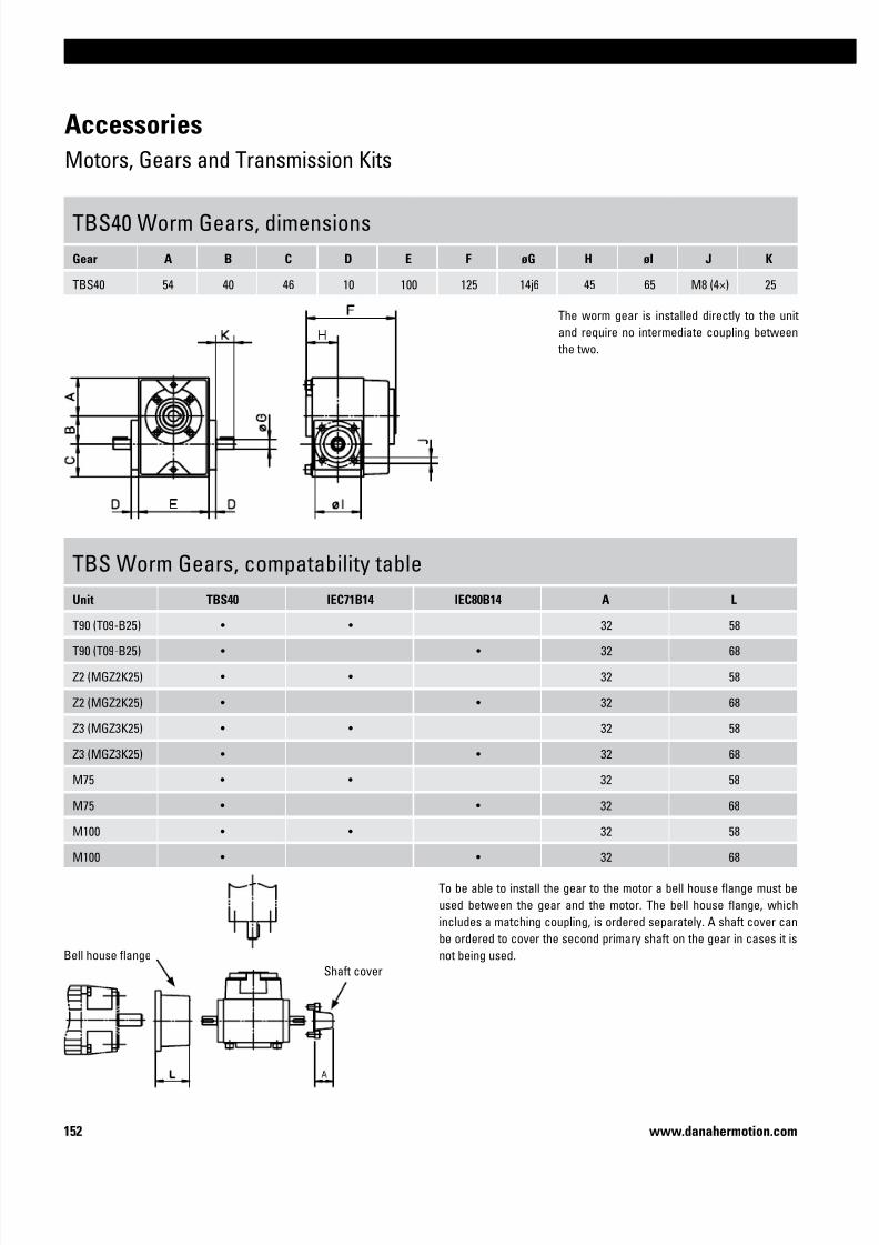
7/23/2019 Linear Actuator Danaher Motion
http://slidepdf.com/reader/full/linear-actuator-danaher-motion 152/224152 www.danahermotion.com
Accessories
Motors, Gears and Transmission Kits
TBS40 Worm Gears, dimensions
Gear A B C D E F øG H øI J K
TBS40 54 40 46 10 100 125 14j6 45 65 M8 (4×) 25
TBS Worm Gears, compatability table
Unit TBS40 IEC71B14 IEC80B14 A L
T90 (T09-B25) • • 32 58
T90 (T09-B25) • • 32 68
Z2 (MGZ2K25) • • 32 58
Z2 (MGZ2K25) • • 32 68
Z3 (MGZ3K25) • • 32 58
Z3 (MGZ3K25) • • 32 68
M75 • • 32 58
M75 • • 32 68
M100 • • 32 58
M100 • • 32 68
The worm gear is installed directly to the unit
and require no intermediate coupling between
the two.
To be able to install the gear to the motor a bell house flange must be
used between the gear and the motor. The bell house flange, which
includes a matching coupling, is ordered separately. A shaft cover can
be ordered to cover the second primary shaft on the gear in cases it is
not being used.Bell house flange
Shaft cover

7/23/2019 Linear Actuator Danaher Motion
http://slidepdf.com/reader/full/linear-actuator-danaher-motion 153/224153
Linear Units
www.danahermotion.com
Accessories
Motors, Gears and Transmission Kits
TBS40 Worm Gears, ordering key
1 2 3
Example TBS40 -3 -216
1. Type and size of worm gear
TBS40 = TBS40 worm gear
2. Gear ratio
-3 = 3:1
-5,5 = 5,5:1
-7,5 = 7,5:1
-10 = 10:1-15 = 15:1
-20 = 20:1
-24 = 24:1
-30 = 30:1
-40 = 40:1
-48 = 48:1
-60 = 60:1
3. Fixed code
-216
Bell house flanges for TBS40 Worm Gears, part numbers
Motor size p/n
IEC71B14 D701 011
IEC80B14 D701 015
Shaft Cover for TBS40 Worm Gears, part numbers
Gear type p/n
TBS40 D701 020

7/23/2019 Linear Actuator Danaher Motion
http://slidepdf.com/reader/full/linear-actuator-danaher-motion 154/224154 www.danahermotion.com
Accessories
Motors, Gears and Transmission Kits
RT Belt Gears, dimensions
Gear A B C D
RT40 110 30 176 68
RT60 175 74 345 170
RT80 175 74 345 170
RT40 RT60/80
RT Belt Gears, data
Gear i nmax [rpm] Mmax [Nm] M idle [Nm] h J [kgm2] Weight [kg}
RT40 1:1 3000 1,75 0,3 0,80 0,000025 0,62
RT60 1:1 3000 15 0,7 0,85 0,000438 5,6
RT60 2:1 3000 15 0,7 0,85 0,001011 7,1
RT80 1:1 3000 30 0,7 0,85 0,000465 5,5
RT80 2:1 3000 30 0,7 0,85 0,001038 7
i = gear ratio M idle = idle torque
nmax = max. input speed h = efficiency factor
Mmax = max. input torque J = inertia

7/23/2019 Linear Actuator Danaher Motion
http://slidepdf.com/reader/full/linear-actuator-danaher-motion 155/224155
Linear Units
www.danahermotion.com
Accessories
Motors, Gears and Transmission Kits
RT Belt Gears, compatability table
Gear WH40 / WM40 WM60 / WV60 / WZ60 / MLSM60D WH80 / WM80 / WV80 / WM120 / WV120 / MLSM60D / MLSM80D
RT40 •
RT60 •
RT80 •
RT Belt Gears, ordering key
1 2 3 4 5
Example RT80 -2 -• • • -P-N -05
1. Type and size of belt gear
RT40 = RT belt gear size 40
RT60 = RT belt gear size 60
RT80 = RT belt gear size 80
2. Gear ratio
-1 = 1:1-2 = 2:1
3. Motor code
- • • • = alphanumeric motor code (e.g. -AK5).
There are several motors that fits each gear
and the list of suitable motors is continiously
being updated. Please contact customer sup-
port for help to see which motors currently
are on the list or if your prefered motor can beadded to the list.
4. Type of mounting
-P-M = gear supplied mounted to the unit
-P-N = gear supplied unmounted
5. Compatable unit type
-01 = WH40
-02 = WH50
-03 = WH80
-04 = WH120
-05 = WM40
-06 = WM60-07 = WM80
-08 = WM120
-09 = WV60
-10 = WV80
-11 = WV120
-12 = WHZ50
-13 = WHZ80
-14 = WZ60
-15 = WZ80
-16 = MLSH60Z
-17 = MLSH80Z
-18 = MLSM80Z
-19 = MLSM60D
-20 = MLSM80D

7/23/2019 Linear Actuator Danaher Motion
http://slidepdf.com/reader/full/linear-actuator-danaher-motion 156/224156 www.danahermotion.com
Accessories
Motors, Gears and Transmission Kits
BGM Belt Gears, dimensions
Gear A B C D øE F G H I J
BGM09 118,7 52 255 140 20 H9 95 115 60 – –
BGM41 155,2 70 305 165 25 H9 122 147 70 – –
BGM81 200 73 399 224 30 H9 134 159 90 90H14 170
BGM09/41/81 - WITHOUT CLEVIS OPTION
BGM09/41/81 - WITH CLEVIS OPTION TYPE S BGM81 - WITH CLEVIS OPTION TYPE R
The belt gear comes in parts and is
assembled to the unit and motor by
the customer.

7/23/2019 Linear Actuator Danaher Motion
http://slidepdf.com/reader/full/linear-actuator-danaher-motion 157/224157
Linear Units
www.danahermotion.com
BGM Belt Gears, ordering keys
Accessories
Motors, Gears and Transmission Kits
BGM Belt Gears, data
Gear i nmax [rpm] Mmax [Nm] h J [kgm2] Weight [kg}
BGM09 1,04:1 4000 3,3 0,85 0,000102 2
BGM09 1,85:1 4000 3,3 0,85 0,000112 2,1
BGM09 2,85:1 4000 3,3 0,85 0,000213 2,5
BGM41 1:1 4000 16,6 0,85 0,000438 3,4
BGM41 2:1 4000 9,7 0,85 0,000342 3,7
BGM41 3:1 4000 9,7 0,85 0,000583 4,6
BGM81 1:1 4000 32 0,85 0,000836 12,1
BGM81 2,25:1 4000 30 0,85 0,001051 12,9
BGM81 3,13:1 4000 28 0,85 0,001439 14
i = gear ratio h = efficiency factor
nmax = max. input speed J = inertia
Mmax = max. input torque
BGM Belt Gears, compatability tableGear WM/V/Z60 WM/V80 WM/V120 MLSM60D/80D MLSH80Z WB60 M50 M55 M75 M100 Z2 T90 (T09-B25) T90 (T09-B32) T130
BGM09 • • • • • •
BGM41 • • • • • • • •
BGM81 • • • •
See next page for ordering keys.
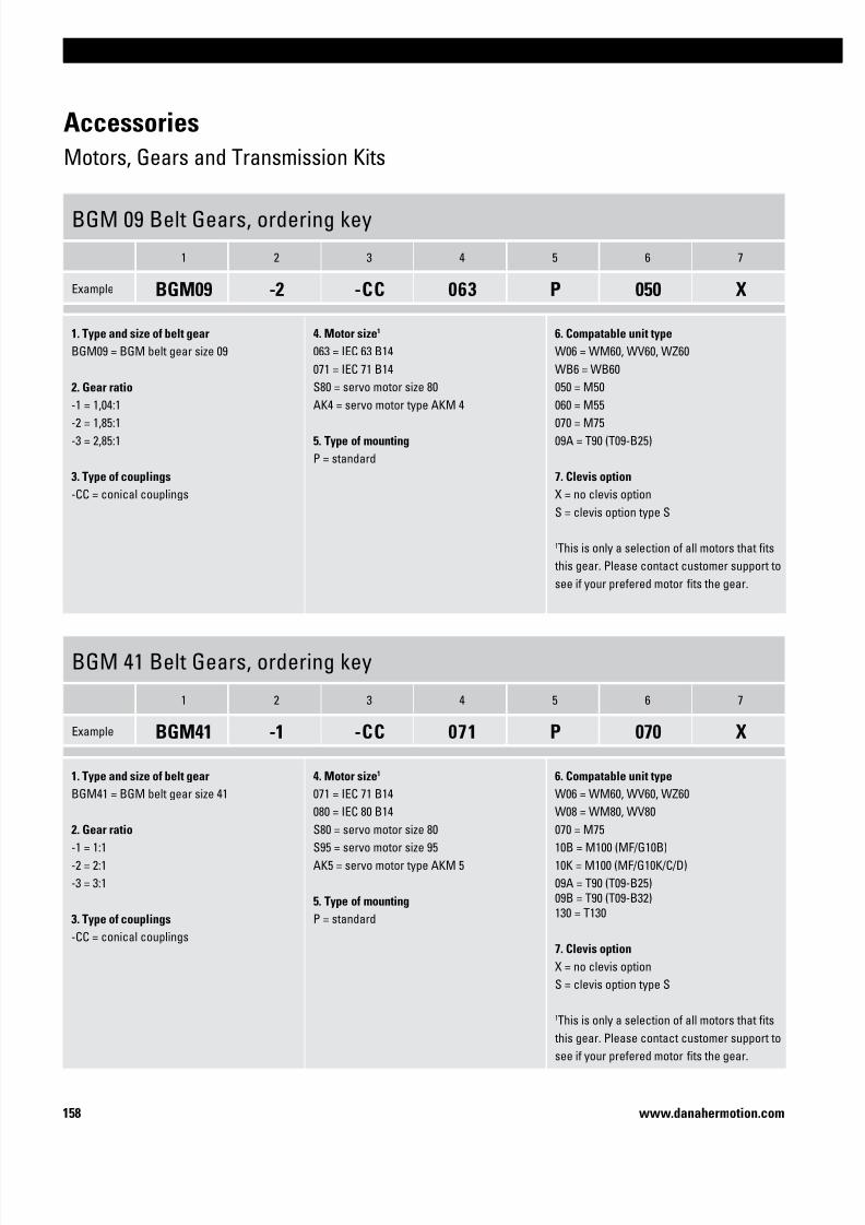
7/23/2019 Linear Actuator Danaher Motion
http://slidepdf.com/reader/full/linear-actuator-danaher-motion 158/224158 www.danahermotion.com
Accessories
Motors, Gears and Transmission Kits
BGM 09 Belt Gears, ordering key
1 2 3 4 5 6 7
Example BGM09 -2 -CC 063 P 050 X
1. Type and size of belt gear
BGM09 = BGM belt gear size 09
2. Gear ratio
-1 = 1,04:1-2 = 1,85:1
-3 = 2,85:1
3. Type of couplings
-CC = conical couplings
4. Motor size1
063 = IEC 63 B14
071 = IEC 71 B14
S80 = servo motor size 80
AK4 = servo motor type AKM 4
5. Type of mounting
P = standard
6. Compatable unit type
W06 = WM60, WV60, WZ60
WB6 = WB60
050 = M50
060 = M55070 = M75
09A = T90 (T09-B25)
7. Clevis option
X = no clevis option
S = clevis option type S
1This is only a selection of all motors that fits
this gear. Please contact customer support to
see if your prefered motor fits the gear.
BGM 41 Belt Gears, ordering key
1 2 3 4 5 6 7
Example BGM41 -1 -CC 071 P 070 X
1. Type and size of belt gear
BGM41 = BGM belt gear size 41
2. Gear ratio
-1 = 1:1
-2 = 2:1
-3 = 3:1
3. Type of couplings
-CC = conical couplings
4. Motor size1
071 = IEC 71 B14
080 = IEC 80 B14S80 = servo motor size 80
S95 = servo motor size 95
AK5 = servo motor type AKM 5
5. Type of mounting
P = standard
6. Compatable unit type
W06 = WM60, WV60, WZ60
W08 = WM80, WV80070 = M75
10B = M100 (MF/G10B)
10K = M100 (MF/G10K/C/D)
09A = T90 (T09-B25)
09B = T90 (T09-B32)
130 = T130
7. Clevis option
X = no clevis option
S = clevis option type S
1
This is only a selection of all motors that fits this gear. Please contact customer support to
see if your prefered motor fits the gear.

7/23/2019 Linear Actuator Danaher Motion
http://slidepdf.com/reader/full/linear-actuator-danaher-motion 159/224159
Linear Units
www.danahermotion.com
Accessories
Motors, Gears and Transmission Kits
BGM 81 Belt Gears, ordering key
1 2 3 4 5 6 7
Example BGM81 -1 -CC 090 P M6D X
1. Type and size of belt gear
BGM81 = BGM belt gear size 81
2. Gear ratio
-1 = 1:1-2 = 2,25:1
-3 = 3,13:1
3. Type of couplings
-CC = conical couplings
4. Motor size1
090 = IEC 90 B14
100 = IEC 100/121 B14
A20 = servo motor size A200
AK6 = servo motor type AKM 6
5. Type of mounting
P = standard
6. Compatable unit type
W12 = WM120, WV120
M6D = MLSM60D
M8D = MLSM80D
M8Z = MLSH80Z130 = T130
7. Clevis option
X = no clevis option
S = clevis option type S
R = clevis option type R
1This is only a selection of all motors that fits
this gear. Please contact customer support to
see if your prefered motor fits the gear.

7/23/2019 Linear Actuator Danaher Motion
http://slidepdf.com/reader/full/linear-actuator-danaher-motion 160/224160 www.danahermotion.com
Accessories
Motors, Gears and Transmission Kits
Unit adaptor flange
UnitBevel gear
Motor adaptor flange
Motor
The bevel gear comes
mounted from factory.
To get a complete gear
you must choose correct
unit adaptor flange, bevel
gear and motor adaptor
flange. A matching cou-pling between the motor
and the motor adaptor
flange is included.
KRG VL0/1/2-Ba40 Bevel Gears, dimensions
Unit Gear Unit adaptor flange p/nBevel gear p/n
A øB øC øDi = 1:1 i = 2:1
WM40 VL0-Ba40 89 10 92 05 20 89 01 50 33 – 65 44 44 12
WM60 / WV60 / WZ60 VL0-Ba40 89 10 92 09 96 89 01 50 33 – 65 64,5 64,5 12
WM60 / WV60 / WZ60 VL1-Ba40 89 10 92 00 59 03 27 05 00 21 03 27 05 00 22 90 90 60 18
WM80 / WV80 VL1-Ba40 89 10 92 00 62 03 27 05 00 21 03 27 05 00 22 90 90 60 18
WM120 / WV120 VL2-Ba40 89 10 92 00 65 03 27 05 00 25 03 27 05 00 26 120 120 80 25
MLSM60D VL1-Ba40 89 10 92 08 69 03 27 05 00 21 03 27 05 00 22 90 90 60 18
MLSM60D VL2-Ba40 89 10 92 08 70 03 27 05 00 25 03 27 05 00 26 120 120 80 25
MLSM80D VL2-Ba40 89 10 92 10 20 03 27 05 00 25 03 27 05 00 26 120 120 80 25
EXPIRING MODEL!This gear will soon be replaced and should not be
used for new projects. Please contact customer
service for more information.

7/23/2019 Linear Actuator Danaher Motion
http://slidepdf.com/reader/full/linear-actuator-danaher-motion 161/224161
Linear Units
www.danahermotion.com
F G K L M P øT X Motor Motor adaptor flange p/n Y
100 11,5 M6 26 2 22,5 54 113 DBL3N00300 89 10 92 09 97 143
100 9,5 M6 26 2 22,5 54 121 DBL3N00300 89 10 92 09 97 143
122 12 M8 35 2 35 75 144
DBL4N 89 10 92 00 60 180
DBL5N 89 10 92 00 79 190
DBL7N 89 10 92 00 80 200
122 12 M8 35 2 35 75 144
DBL4N 89 10 92 00 60 180
DBL5N 89 10 92 00 79 190
DBL7N 89 10 92 00 80 200
162 15 M10 45 2 50 100 185
DBL4N 89 10 92 01 30 222
DBL5N 89 10 92 00 66 232
DBL7N 89 10 92 00 72 240
122 12 M8 35 2 35 75 143
DBL4N 89 10 92 00 60 180
DBL5N 89 10 92 00 79 190
DBL7N 89 10 92 00 80 200
163 15 M10 45 2 50 100 170
DBL4N 89 10 92 01 30 222
DBL5N 89 10 92 00 66 232DBL7N 89 10 92 00 72 240
163 15 M10 45 2 50 100 170
DBL4N 89 10 92 01 30 222
DBL5N 89 10 92 00 66 232
DBL7N 89 10 92 00 72 240
KRG VL0/1/2-Ba40 Bevel Gears, data
Gear
Mmax [Nm] nmax
[rpm]
M idle
[Nm] h
J [kgm2] Weight
[kg]
Backlash
[arc min]i = 1:1 i = 2:1 i = 1:1 i = 2:1
VL0-Ba40 10 – 3000 0,1 0,97 0,000062 0,00002 2 10
VL1-Ba40 28 28 3000 0,15 0,97 0,000358 0,000088 5,5 10
VL2-Ba40 60 60 3000 0,3 0,97 0,001202 0,000421 12 10
i = gear ratio
h = efficiency factor
J = inertia
i = gear ratio
nmax = max. input speed
Accessories
Motors, Gears and Transmission Kits
Mmax = max. input torque
M idle = idle torque
EXPIRING MODEL!This gear will soon be replaced and should not be
used for new projects. Please contact customer
service for more information.

7/23/2019 Linear Actuator Danaher Motion
http://slidepdf.com/reader/full/linear-actuator-danaher-motion 162/224162 www.danahermotion.com
Accessories
Motors, Gears and Transmission Kits
The bevel gear comes
mounted from factory.
To get a complete gear
you must choose correct
unit adaptor flange, bevel
gear and motor adaptor
flange. A matching cou-pling between the motor
and the motor adaptor
flange is included.Unit adaptor flange
UnitBevel gear
Motor adaptor
flange
Motor
KRG VL0/1/2-Ba53 Bevel Gears, dimensions
Unit Gear Unit adaptor flange p/nBevel gear p/n
A øB øC øDi = 1:1 i = 2:1
WM40 VL0-Ba53 89 10 92 05 20 03 27 05 00 29 – 65 44 44 12
WM60 / WV60 / WZ60 VL0-Ba53 89 10 92 09 96 03 27 05 00 29 – 65 64,5 64,5 12
WM60 / WV60 / WZ60 VL1-Ba53 89 10 92 00 59 03 27 05 00 23 03 27 05 00 24 90 90 60 18
WM80 / WV80 VL1-Ba53 89 10 92 00 62 03 27 05 00 23 03 27 05 00 24 90 90 60 18
WM120 / WV120 VL2-Ba53 89 10 92 00 65 03 27 05 00 27 03 27 05 00 28 120 120 80 25
MLSM60D VL1-Ba53 89 10 92 08 62 03 27 05 00 23 03 27 05 00 24 90 90 60 18
MLSM60D VL2-Ba53 89 10 92 08 70 03 27 05 00 27 03 27 05 00 28 120 120 80 25
MLSM80D VL2-Ba53 89 10 92 10 20 03 27 05 00 27 03 27 05 00 28 120 120 80 25
EXPIRING MODEL!This gear will soon be replaced and should not be
used for new projects. Please contact customer
service for more information.

7/23/2019 Linear Actuator Danaher Motion
http://slidepdf.com/reader/full/linear-actuator-danaher-motion 163/224163
Linear Units
www.danahermotion.com
KRG VL0/1/2-Ba53 Bevel Gears, data
GearMmax [Nm] nmax
[rpm]
M idle
[Nm] h
J [kgm2] Weight
[kg]
Backlash
[arc min]i = 1:1 i = 2:1 i = 1:1 i = 2:1
VL0-Ba53 10 – 3000 0,2 0,97 0,000088 0,000043 2,5 10
VL1-Ba53 28 28 3000 0,3 0,97 0,000396 0,000126 6,5 10
VL2-Ba53 60 60 3000 0,5 0,97 0,001369 0,000288 15 10
h = efficiency factor
J = inertia
i = gear ratio
nmax = max. input speed
Mmax = max. input torque
M idle = idle torque
F G K L M P øT X Motor* Motor adaptor flange p/n Y
100 11,5 M6 26 2 22,5 54 113 DBL3N00300 89 10 92 09 97 143
100 9,5 M6 26 2 22,5 54 121 DBL3N00300 89 10 92 09 97 143
122 12 M8 35 2 35 75 144
DBL4N 89 10 92 00 60 180
DBL5N 89 10 92 00 79 190
DBL7N 89 10 92 00 80 200
122 12 M6 35 2 35 75 144
DBL4N 89 10 92 00 60 180
DBL5N 89 10 92 00 79 190
DBL7N 89 10 92 00 80 200
162 15 M10 45 2 50 100 185
DBL4N 89 10 92 01 30 222
DBL5N 89 10 92 00 66 232
DBL7N 89 10 92 00 72 240
122 12 M8 35 2 35 75 143
DBL4N 89 10 92 00 60 180
DBL5N 89 10 92 00 79 190
DBL7N 89 10 92 00 80 200
163 15 M10 45 2 50 100 170
DBL4N 89 10 92 01 30 222
DBL5N 89 10 92 00 66 232DBL7N 89 10 92 00 72 240
163 15 M10 45 2 50 100 170
DBL4N 89 10 92 01 30 222
DBL5N 89 10 92 00 66 232
DBL7N 89 10 92 00 72 240
i = gear ratio * other motors available on request.
EXPIRING MODEL!This gear will soon be replaced and should not be
used for new projects. Please contact customer
service for more information.

7/23/2019 Linear Actuator Danaher Motion
http://slidepdf.com/reader/full/linear-actuator-danaher-motion 164/224164 www.danahermotion.com
Accessories
Motors, Gears and Transmission Kits
Micron DT, DTR Planetary Gears, compatability and dimensions
Unit Gear i A B C D E Weight [kg] Backlash [arc min] Efficiency [%]
WH50
DT60-SS 3:1 - 10:1 89,7 60 – – – 1 8 90
DT60-DS 15:1 - 100:1 106,9 60 – – – 1,2 9 85
DTR60-SS 5:1 - 50:1 – – 110,2 104,1 60 2,5 9 90
DTR60-DS 60:1 - 500:1 – – 127,3 104,1 60 2,7 9 85
WH80
DT90-SS 3:1 - 10:1 110,9 90 – – – 3 9 90
DT90-DS 15:1 - 100:1 133,5 90 – – – 3,7 9 85
DTR90-SS 5:1 - 50:1 – – 145,4 138,2 90 4,8 9 90
DTR90-DS 60:1 - 500:1 – – 168,0 138,2 90 5,5 9 85
WH120
DT115-SS 3:1 - 10:1 136,4 110 – – – 12,7 8 90
DT115-DS 15:1 - 100:1 167,4 110 – – – 16,2 9 85
DTR115-SS 5:1 - 50:1 – – 185,7 173,5 115 11 8 90
DTR115-DS 60:1 - 500:1 – – 216,7 173,5 115 12 9 85
WM60Z
DT60-SS 3:1 - 10:1 89,7 60 – – – 1 8 90
DT60-DS 15:1 - 100:1 106,9 60 – – – 1,2 9 85
DTR60-SS 5:1 - 50:1 – – 110,2 104,1 60 2,5 9 90
DTR60-DS 60:1 - 500:1 – – 127,3 104,1 60 2,7 9 85
WM80Z
DT90-SS 3:1 - 10:1 110,9 90 – – – 3 9 90DT90-DS 15:1 - 100:1 133,5 90 – – – 3,7 9 85
DTR90-SS 5:1 - 50:1 – – 145,4 138,2 90 4,8 9 90
DTR90-DS 60:1 - 500:1 – – 168,0 138,2 90 5,5 9 85
i = gear ratio
DT DTR
Left side Right side Position 1 Position 2
Position 3 Position 4
Micron DT and DTR planetary gears comes mounted on the unit from factory.

7/23/2019 Linear Actuator Danaher Motion
http://slidepdf.com/reader/full/linear-actuator-danaher-motion 165/224165
Linear Units
www.danahermotion.com
Accessories
Motors, Gears and Transmission Kits
1. Size of planetary gear
DT60DT90
DT115
2. Type of gear
-SS
-DS
3. Mounting side of the unit
Left
Right
4. Gear ratio
3:1 (only for -SS models)
5:1 (only for -SS models)
10:1 (only for -SS models)
15:1 (only for -DS models)
25:1 (only for -DS models)
30:1 (only for -DS models)
50:1 (only for -DS models)
100:1 (only for -DS models)
5. Motor
Specify your choice of motor.
1. Type and size of planetary gear
DTR60
DTR90
DTR115
2. Type of gear
-SS
-DS
3. Mounting position of the gear
Position 1
Position 2
Position 3Position 4
4. Mounting side of the unitl
Left
Right
5. Gear ratio
5:1 (only for -SS models)
6:1 (only for -SS models)
9:1 (only for -SS models)
10:1 (only for -SS models)
12:1 (only for -SS models)
15:1 (only for -SS models)
20:1 (only for -SS models)
25:1 (only for -SS models)
30:1 (only for -SS models)
40:1 (only for -SS models)
50:1 (only for -SS models)
60:1 (only for -DS models)75:1 (only for -DS models)
90:1 (only for -DS models)
100:1 (only for -DS models)
120:1 (only for -DS models)
125:1 (only for -DS models)
150:1 (only for -DS models)
200:1 (only for -DS models)
250:1 (only for -DS models)
300:1 (only for -DS models)
400:1 (only for -DS models)
500:1 (only for -DS models)
6. Motor
Specify your choice of motor.
Micron DT, DTR Planetary Gears, how to order
When ordering a DT or DTR planetary gear you need to state the size and type of gear, which side of the unit the gear shall be installed, the gear
ratio and which motor that you wish to use. For DTR you also must state the prefered mounting position of the gear. With this information we can
check if your choice of motor is possible or not and give you the correct ordering code for the gear.
Micron DT, ordering data Micron DTR, ordering data

7/23/2019 Linear Actuator Danaher Motion
http://slidepdf.com/reader/full/linear-actuator-danaher-motion 166/224166 www.danahermotion.com
Accessories
Motors, Gears and Transmission Kits
VWZ Intermediate Shafts, dimensions
Shaft øA B C D øE F min. G
VWZ-30 32 15 1,5 34 30 99 M4
VWZ-40 42 17 1,5 46 40 133 M5
VWZ-60 56 30 2 63 60 177 M6
VWZ-60V 67 35 2 73 60 205 M8
VWZ-80 82 40 2 84 80 249 M10
VWZ-100 102 50 2 97 100 283 M12
Mmax = max. shaft torque Gc = weight of coupling Jc = inertia of coupling
Gs = weight of shaft Js = inertia of shaft Ms = tightening torque
VWZ Intermediate Shafts, data
Shaft Mmax [Nm] Gs [kg/m] Gc [kg] Js [kgm2 /m] Jc [kgm2] Ms [Nm]
VWZ-30 4,8 0,58 0,14 0,00011 0,00001 4
VWZ-40 6,4 0,76 0,36 0,00020 0,00008 8
VWZ-60 22,7 0,97 0,94 0,00080 0,00024 15
VWZ-60V 60,6 0,97 1,42 0,00080 0,00046 35
VWZ-80 122,7 2,00 2,98 0,00300 0,00240 70
VWZ-100 169,7 2,47 4,62 0,00580 0,00600 120
The VWZ intermediate shafts can be installed in two ways. Either
directly to belt driven units (I) or to screw driven units using KRG
bevel gears (II) of type VL0, VL1 or VL2. The intermediate shaft
includes tube and couplings.
Critical Speed of Shaft
1: VWZ-302: VWZ-40
3: VWZ-60 and VWZ-60V4: VWZ-80
5: VWZ-100

7/23/2019 Linear Actuator Danaher Motion
http://slidepdf.com/reader/full/linear-actuator-danaher-motion 167/224167
Linear Units
www.danahermotion.com
Accessories
Motors, Gears and Transmission Kits
VWZ Intermediate Shafts, compatability table
Unit I I I VWZ-30 VWZ-40 VWZ-60 VWZ-60V VWZ-80 VWZ-100 AA [mm]
WH40 • • AA = L + 56
WH50 / WHZ50 • • AA = L + 54
WM60Z • • AA = L + 64
WH80 / WHZ80 • • AA = L + 84
WH120 • • AA = L + 124
WM80Z • • AA = L + 84
MLSH60Z • • AA = L + 164
WB40 / WM40 VL0 • AA = L + 170
WB60 VL1 • AA = L + 210
WM60 / WV60 / WZ60 VL1 • AA = L + 184
WM80 / WV80 / MLSM60D VL1 • AA = L + 176
MLSH80Z / MLSM80Z • • AA = L + 244
WM120 / WV120 / MLSM60D / MLSM80D VL2 • AA = L + 244
AA = C/C distance between units
L = total length of shaft and coupling assembly
VWZ Intermediate Shafts, ordering key
1 2 3
Example VWZ-060 -02 -0700
1. Intermediate shaft size
VWZ-030 = VWZ-30
VWZ-040 = VWZ-40VWZ-060 = VWZ-60
VWZ-06V = VWZ-60V
VWZ-080 = VWZ-80
VWZ-100 = VWZ-100
2. Type of unit and type of mounting
-01 = WH40 for type I mounting
-02 = WH50 / WHZ50 for type I mounting-03 = WM80Z for type I mounting
-04 = WH80 / WHZ80 for type I mounting
-05 = WH120 for type I mounting
-03 = WM60Z for type I mounting
-07 = MLSH60Z for type I mounting
-08 = WB40 / WM40 for type II mounting on VLO gears
-09 = WB60 for type II mounting on VL1 gears
-10 = WM60 / WV60 / WZ60 for type II mounting on VL1 gears
-11 = WM80 / WV80 / MLSM60D for type II mounting on VL1 gears
-12 = MLSH80Z / MLSM80Z for type I mounting
-13 = WM120 / WV120 / MLSM60D / MLSM80D for type II mounting on VL2 gears
3. C/C distance between units (AA)

7/23/2019 Linear Actuator Danaher Motion
http://slidepdf.com/reader/full/linear-actuator-danaher-motion 168/224168 www.danahermotion.com
Accessories
Motors, Gears and Transmission Kits
DSP Intermediate Shafts, data
Shaft Weight of shaft [kg] Max. speed [rpm] Shaft diameter [mm]
DSP-05B 0,3 + 1,3 × Lm 1500 20
DSP-06B 0,3 + 1,3 × Lm 1500 20
DSP-07B 0,6 + 2,6 × Lm 1500 30
DSP-10B 0,6 + 2,6 × Lm 1500 30
DSB--ZB 0,6 + 2,6 × Lm 1500 30
DSP-TBS 0,6 + 2,6 × Lm 1500 30The DSP intermediate shaft can be installed directly between two
belt driven units or between two screw driven units using a TBS
worm gear. Couplings and tube is included in the shipment. Support
bearings may need to be installed if the critical speed of the shaft is
exceeded. See diagram. Support bearings can be ordered from your
local bearing supplier.
Critical Speed of Shaft
1: No support bearing required2: Support bearing required for DSP-05B and DSP-06B
3: Support bearing always required
DSP-05B/06B/07B/10B/-ZB DSP-TBS
Lm = C/C distance between units in cm

7/23/2019 Linear Actuator Danaher Motion
http://slidepdf.com/reader/full/linear-actuator-danaher-motion 169/224169
Linear Units
www.danahermotion.com
Accessories
Motors, Gears and Transmission Kits
DSP Intermediate Shafts, compatability table
Unit Drive type DSP-05B DSP-06B DSP-07B DSP-10B DSP--ZB DSP-TBS
M50 belt •
M55 belt •
M75 belt •
M100 belt •
ZB belt •
M55 screw •
M75 screw •
M100 screw •
DSP Intermediate Shafts, ordering key
1 2
Example DSP-06B -305
1. Intermediate shaft size and type
DSP-05B = for belt driven M50 units
DSP-06B = for belt driven M55 units
DSP-07B = for belt driven M75 units
DSP-10B = for belt driven M100 units
DSP--ZB = for belt driven ZB units
DSP-TBS = for screw driven M55, M75 or M100 units with TBS worm gear
2. C/C distance between units in cm (Lm)
- • • • = length in cm

7/23/2019 Linear Actuator Danaher Motion
http://slidepdf.com/reader/full/linear-actuator-danaher-motion 170/224170 www.danahermotion.com
Accessories
Motors, Gears and Transmission Kits
AKM Servo Motor with brake, dimensions
Motor p/n øA øC øD E F øG K L
AKM23D-AN
S e e o r d e r i n g d a t a i n m o t o r c a t a l o g u e
40 63 9 58 90 4,8 124,2 20
AKM32D-AN 60 75 14 70 109 5,8 140,8 30
AKM42D-AN 80 100 19 84 123 7 147,8 40
AKM43D-AN 80 100 19 84 123 7 176,8 40
AKM52D-AN 110 130 24 108 147 9 158,5 50
AKM53D-AN 110 130 24 108 147 9 189,5 50
AKM63D-AN 130 165 32 138 177 11 178,7 58
AKM64D-AN 130 165 32 138 177 11 203,7 58
AKM72D-AN 180 215 38 188 227 13,5 192,5 80
AKM74D-AN 180 215 38 188 227 13,5 226,5 80
AKM Servo Motor with brake, data
Motor Mo [Nm] Mn [Nm] Io [A] Jmot [kgm2] Gmot [kg] Mbr [Nm] Ibr [A] Jbr [kgm2] Gbr [kg]
AKM23D-AN 1,16 0,92 2,19 0,000022 1,38 1,42 0,35 0,0000011 0,27
AKM32D-AN 2,04 1,65 2,23 0,000059 2,23 2,5 0,42 0,0000011 0,35
AKM42D-AN 3,42 2,81 2,74 0,00015 3,39 6 0,54 0,0000068 0,63
AKM43D-AN 4,8 3,01 4,87 0,00021 4,35 6 0,54 0,0000068 0,63
AKM52D-AN 8,6 3,9 9,3 0,00062 5,8 14,5 0,81 0,0000173 1,1
AKM53D-AN 11,6 7,65 9,4 0,00091 7,4 14,5 0,81 0,0000173 1,1
AKM63D-AN 16,8 14,9 9,9 0,0024 11,1 25 1,07 0,000061 2
AKM64D-AN 21 15,6 12,8 0,0032 13,3 25 1,07 0,000061 2
AKM72D-AN 29,4 20,1 18,7 0,0065 19,7 53 1,48 0,000164 2,1
AKM74D-AN 41,6 28,5 19,5 0,0092 26,7 53 1,48 0,000164 2,1
Mo = standstill torque
Mn = nominal torque
Io = standstill current
Jmot = rotor inertia
Gmot = weight of motor
Mbr = brake torque
Ibr = brake currentJbr = brake inertia
Gbr = weight of brake
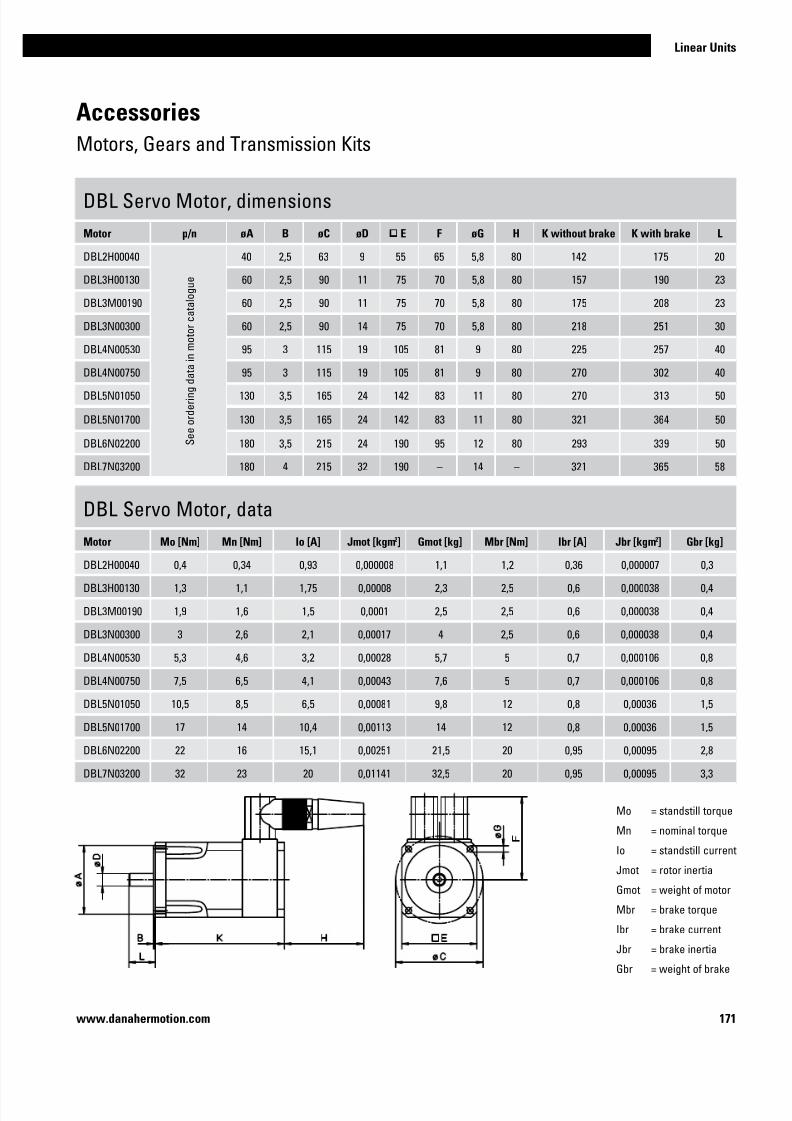
7/23/2019 Linear Actuator Danaher Motion
http://slidepdf.com/reader/full/linear-actuator-danaher-motion 171/224171
Linear Units
www.danahermotion.com
Accessories
Motors, Gears and Transmission Kits
DBL Servo Motor, dimensions
Motor p/n øA B øC øD E F øG H K without brake K with brake L
DBL2H00040
S e e o r d e r i n g d a t a i n m o t o r c a t a l o g u e
40 2,5 63 9 55 65 5,8 80 142 175 20
DBL3H00130 60 2,5 90 11 75 70 5,8 80 157 190 23
DBL3M00190 60 2,5 90 11 75 70 5,8 80 175 208 23
DBL3N00300 60 2,5 90 14 75 70 5,8 80 218 251 30
DBL4N00530 95 3 115 19 105 81 9 80 225 257 40
DBL4N00750 95 3 115 19 105 81 9 80 270 302 40
DBL5N01050 130 3,5 165 24 142 83 11 80 270 313 50
DBL5N01700 130 3,5 165 24 142 83 11 80 321 364 50
DBL6N02200 180 3,5 215 24 190 95 12 80 293 339 50
DBL7N03200 180 4 215 32 190 – 14 – 321 365 58
DBL Servo Motor, data
Motor Mo [Nm] Mn [Nm] Io [A] Jmot [kgm2] Gmot [kg] Mbr [Nm] Ibr [A] Jbr [kgm2] Gbr [kg]
DBL2H00040 0,4 0,34 0,93 0,000008 1,1 1,2 0,36 0,000007 0,3
DBL3H00130 1,3 1,1 1,75 0,00008 2,3 2,5 0,6 0,000038 0,4
DBL3M00190 1,9 1,6 1,5 0,0001 2,5 2,5 0,6 0,000038 0,4
DBL3N00300 3 2,6 2,1 0,00017 4 2,5 0,6 0,000038 0,4
DBL4N00530 5,3 4,6 3,2 0,00028 5,7 5 0,7 0,000106 0,8
DBL4N00750 7,5 6,5 4,1 0,00043 7,6 5 0,7 0,000106 0,8
DBL5N01050 10,5 8,5 6,5 0,00081 9,8 12 0,8 0,00036 1,5
DBL5N01700 17 14 10,4 0,00113 14 12 0,8 0,00036 1,5
DBL6N02200 22 16 15,1 0,00251 21,5 20 0,95 0,00095 2,8
DBL7N03200 32 23 20 0,01141 32,5 20 0,95 0,00095 3,3
Mo = standstill torque
Mn = nominal torque
Io = standstill current
Jmot = rotor inertia
Gmot = weight of motor
Mbr = brake torque
Ibr = brake currentJbr = brake inertia
Gbr = weight of brake

7/23/2019 Linear Actuator Danaher Motion
http://slidepdf.com/reader/full/linear-actuator-danaher-motion 172/224172 www.danahermotion.com
Accessories
Electrical Feedback Devices
Limit Switch Brackets1
Unit type I For limit switch type I I For limit switch type
M50 D393 035 XCM-A115 – –
M55 D313 427 XCM-A115 D313 428 XCM-A115
M75 D312 860 XCK-M115 D312 861 XCK-M115
M100 D312 330 XCK-M115 D312 331 XCK-M115
1 no limit switches included in the shipment.
Limit Switches
Switch type p/n Protection degree Contacts Cable
XCM-A115 D535 102 IP67 NO + NC 1 meter
XCK-M115 D535 107 IP67 NO + NC –
Limit Switch Brackets for Z3
Unit type p/n For limit switch type
Z3 D800 042 XCK-M115
The limit switch brackets are adjustable in height. The limit switches on the brackets are operated
by the maximum extended and maximum retracted end of stroke bars on top of the Z3 units. Two
brackets are required.
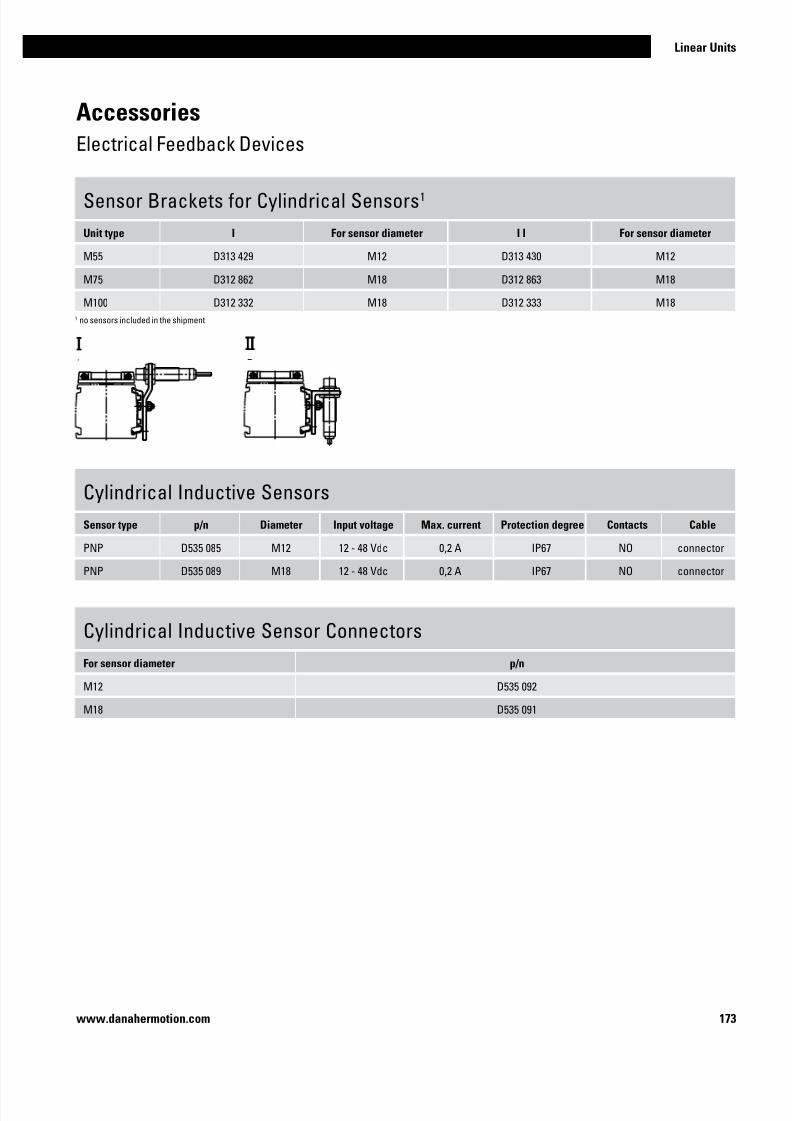
7/23/2019 Linear Actuator Danaher Motion
http://slidepdf.com/reader/full/linear-actuator-danaher-motion 173/224173
Linear Units
www.danahermotion.com
Sensor Brackets for Cylindrical Sensors1
Unit type I For sensor diameter I I For sensor diameter
M55 D313 429 M12 D313 430 M12
M75 D312 862 M18 D312 863 M18
M100 D312 332 M18 D312 333 M18
1 no sensors included in the shipment
Accessories
Electrical Feedback Devices
Cylindrical Inductive Sensors
Sensor type p/n Diameter Input voltage Max. current Protection degree Contacts Cable
PNP D535 085 M12 12 - 48 Vdc 0,2 A IP67 NO connector
PNP D535 089 M18 12 - 48 Vdc 0,2 A IP67 NO connector
Cylindrical Inductive Sensor Connectors
For sensor diameter p/n
M12 D535 092
M18 D535 091

7/23/2019 Linear Actuator Danaher Motion
http://slidepdf.com/reader/full/linear-actuator-danaher-motion 174/224174 www.danahermotion.com
Accessories
Electrical Feedback Devices
EN2 Inductive Sensors, data
Parameter EN2
Supply voltage [Vdc] 10 – 30
Max. load current [A] 0,2
Operating distance [mm) 2
LED indicator for switch yes
Protection class IP67
Cable type screened
Weight with cable L = 2 m
with cable L= 10 m
[kg]0,04
0,19
EN2 Inductive Sensors, part numbers
Sensor type Cable length [m] p/n
Normally closed 2 671 545 0305
Normally open 2 671 545 0304
Normally closed 10 671 545 0307
Normally open 10 671 545 0306
To be able to mount the EN2 inductive sensors on a unit the ENT14x16
sensor rail is required (see page 178) except for units WM120 and WV120where they can be fitted directly to the profile of the unit.
Magnetic Sensors, data
Parameter
Max. power [W] 10
Max. voltage [Vdc] 100
Max. current [A] 0,5
LED indicator for switch no
Protection class IP67
Cable length [m] 3
Cable cross section [mm2] 2 × 0,15
Operating temperature limits [°C] -25 – 65
Weight [kg] 0,050
Magnetic Sensors, part numbers
Sensor type suitable units p/n
Normally closed M50, T90, T130, Z2, Z3 D535 071
Normally open M50, T90, T130, Z2, Z3 D535 070
The magnetic sensors are mounted directly in the sensor slot of the
profiles of the units and require no mounting bracket. The sensor is fixed
in position by two M3 size locking screws (A1). The cable (A2) is molded
into the sensor.
blue
black
blue
black

7/23/2019 Linear Actuator Danaher Motion
http://slidepdf.com/reader/full/linear-actuator-danaher-motion 175/224175
Linear Units
www.danahermotion.com
Accessories
Electrical Feedback Devices
IG602 Encoders, data
Parameter IG602
Supply voltage Type 1
Type 2
[Vdc]5 ±10%
10 – 30
Output type
Type 1
Type 2
line driver
push-pull
Pulses per revolution
Type 1 Type 2
[ppr]
100 – 2500100 – 600
Length (L) Type 1
Type 2
[mm]51,5
56,0
Weight
Type 1
Type 2
[kg]
0,36
0,36
STE001 Encoder Connector, data
Parameter STE001
Number of poles 12
Protection class IP67
Execution jack
Cable entrance straight
Weight [kg] 0,04
Part number 6715600153
IG602 Encoders, part numbers
Encoder type Supply voltage[Vdc)
Pulses perrevolution
p/n
Type 1 5 100 671 521 0194
Type 1 5 200 671 521 0195
Type 1 5 500 671 521 0196
Type 1 5 600 671 521 0197
Type 1 5 1000 671 521 0198
Type 1 5 1250 671 521 0199
Type 1 5 1500 671 521 0200
Type 1 5 2000 671 521 0192
Type 1 5 2500 671 521 0201
Type 2 10 – 30 100 671 521 0193
Type 2 10 – 30 200 671 521 0202
Type 2 10 – 30 500 671 521 0203
Type 2 10 – 30 600 671 521 0204
The IG602 encoders comes with mounting screws but no coupling or
connector. To be able to mount the encoder to the unit the unit must have
a shaft for encoders. See the ordering keys of the units. The encoders
can also be ordered mounted to the unit from factory. See ADG encoderoption kit on page 180.
Encoder Cable, data
Parameter p/n
5 m cable length 671 555 0068
10 m cable length 671 555 0069
The encoder cables come fitted with a STE001 encoder connector in
one of the ends.

7/23/2019 Linear Actuator Danaher Motion
http://slidepdf.com/reader/full/linear-actuator-danaher-motion 176/224176 www.danahermotion.com
ES Limit Switch Option Kit
Unit type I I I I I I A B C D E F G
WH50 1 • 34 60,5 10 26 49 58,5 196
WH80 • 31 76 10 39 49 78,5 196
WH120 • 34 88 10 51 49 78,5 196
WHZ50 • 34 61 10 26 49 58,5 196
WHZ80 • 31 76 10 39 49 78,5 196
WM60 • 40 69 32 38 50 63 200
WM80 • 40 73 32 42 50 79 200
WM120 • 40 89 32 58 50 94 200
WM60Z • 40 69 32 38 50 73 200
WM80Z 2 • 40 73 32 42 50 99 (89) 200
WV60 • 40 69 32 38 50 33 200
WV80 • 40 73 32 42 50 39 200
WV120 • 40 89 32 58 50 59 200
MLSM60D • 40 73 32 32 50 79 200
MLSH60Z • 40 73 32 42 50 79 200
MLSM80D • 40 85 32 54 50 101 200
MLSH80Z • 40 85 32 54 50 101 200
MLSM80Z • 40 85 32 54 50 101 200
WZ60 1 • 60 22,5 16 30 113 53 –
WZ80 1 • 60 22,5 16 30 112 84 –1 limit switches for these units can not be moved. On all other units the switches can be re-positioned by the customer. 2 Value in brackets = for short carriage.
The ES limit switch assembly is an option that is
mounted at the factory. The limit switches are
placed 10 mm from the mechanical ends of the unit.
Each limit switch has one NO and one NC contact
with positive opening action. Protection degree is
IP67. Type I and II switches can be repositioned
along the profile by the customer. Note! the ES limit
switch option and any of the sensor rail options
ENT14x16, ENF14x16 or ENK can not be mounted
on the same side of the unit.
Accessories
Electrical Feedback Devices

7/23/2019 Linear Actuator Danaher Motion
http://slidepdf.com/reader/full/linear-actuator-danaher-motion 177/224177
Linear Units
www.danahermotion.com
Accessories
Electrical Feedback Devices
ES Limit Switch Option Kit, ordering key
1 2 3 4
Example ESK07 -L -01 -10
1. Compatable unit
ESK02 = WH50
ESK03 = WH80
ESK04 = WH120
ESK05 = WM40ESK06 = WM60 / WM60Z
ESK07 = WM80 / WM80Z
ESK08 = WM120
ESK09 = WV60
ESK10 = WV80
ESK11 = WV120
ESK12 = WHZ50
ESK13 = WHZ80
ESK14 = WZ60
ESK15 = WZ80
ESK16 = MLSH60Z
ESK17 = MLSH80Z
ESK18 = MLSM80Z
ESK19 = MLSM60D
ESK20 = MLSM80D
2. Mounting side of the unit
-L = left side
-R = right side
3. Switch configuration on side A-00 = no switch on side A
-01 = switch with 1 m cable
-05 = switch with 5 m cable
-10 = switch with 10 m cable
4. Switch configuration on side B
-00 = no switch on side B
-01 = switch with 1 m cable
-05 = switch with 5 m cable
-10 = switch with 10 m cable

7/23/2019 Linear Actuator Danaher Motion
http://slidepdf.com/reader/full/linear-actuator-danaher-motion 178/224178 www.danahermotion.com
Accessories
Electrical Feedback Devices
ENT14x16 Inductive Sensor Rail
Unit type p/n
WH40 / WH50 / WH80 / WH120 / WHZ50 / WHZ80 / WM40 / WM60 / WM80 / WM60Z / WM80Z / WV60 / WV80 /MLSM60D / MLSM80D / MLSH60Z / MLSH80Z / MLSM80Z / WZ60 / WZ80 / WB40 / WB60
671 545 0283
The ENT14x16 inductive sensor rail is mounted to the side of an unit or along any type of beam or profile. In
the rail inductive sensors of type EN2 can be mounted. The rail can also serve as a cable duct for the sensor
cables. The rail is sealed with a cover which comes with the rail. The rail comes in lengths of max. 3000 mm.
Drilling in the profile of the unit is required when mounting the rail. When ordering, specify part number and
length of the rail. Note1! WM120 and WV120 units do not require any rail as the EN2 sensors can be fitteddirectly to the profile of the units. Note2! ES limit switch option and ENT14x16 rail can not be mounted on the
same side of the unit.
The ENF and ENK inductive sensor rail option kits
are mounted at the factory. The ENF option consists
of two 500 mm long ENT14x16 sensor rails mounted
on in each end of the unit on the left or right side
of the profile. In cases where the unit is to short
to allow two 500 mm sensor rails to be mounted,
then one rail is mounted along the entire profile of
the unit. The ENK option also consists of ENT14 x16
sensor rails but the ENK option has sensor profiles
that runs along the entire profile of the unit. In the
shipment of both ENF and ENK the specified amount
and type of EN2 sensors are included. The sensorsare fitted to the sensor rail by the customer at the
desired positions. Note1! WM120 and WV120 units
do not require any ENF or ENF option as the EN2
sensors can be fitted directly to the profile of the
units. Note2! ES limit switch option and ENF rail can
not be mounted on the same side of the unit.
ENF and ENK Inductive Sensor Rail Option Kit, compatability table
Unit type ENF / ENK
WH40 / WH50 / WH80 / WH120 / WHZ50 / WHZ80 / WM40 / WM60 / WM80 / WM60Z / WM80Z / WV60 /
WV80 / MLSM60D / MLSM80D / MLSH60Z / MLSH80Z / MLSM80Z / WZ60 / WZ80 / WB40 / WB60•
ENF
ENK

7/23/2019 Linear Actuator Danaher Motion
http://slidepdf.com/reader/full/linear-actuator-danaher-motion 179/224179
Linear Units
www.danahermotion.com
Accessories
Electrical Feedback Devices
ENK and ENF Inductive Sensor Rail Option Kit, ordering key
1 2 3 4 5 6 7 8
Example ENK16 -S -04000 -R -2 -0 -1 -6
1. Type of rail and compatable unit
ENK01 = ENK rail for WH40
ENK02 = ENK rail for WH50
ENK03 = ENK rail for WH80
ENK04 = ENK rail for WH120ENK05 = ENK rail for WM40
ENK06 = ENK rail for WM60 / WV60
ENK07 = ENK rail for WM80 / WV80
ENK08 = ENK rail for WM120 / WV120
ENK09 = ENK rail for WM60Z
ENK10 = ENK rail for WM80Z
ENK11 = ENK rail for WHZ50
ENK12 = ENK rail for WHZ80
ENK13 = ENK rail for WZ60
ENK14 = ENK rail for WZ80
ENK15 = ENK rail for MLSH60Z
ENK16 = ENK rail for MLSH80Z
ENK17 = ENK rail for MLSM80Z
ENK18 = ENK rail for MLSM60D
ENK19 = ENK rail for MLSM80D
ENK20 = ENK rail for WB40
ENK21 = ENK rail for WB60
ENF01 = ENF rail for WH40
ENF02 = ENF rail for WH50
ENF03 = ENF rail for WH80
ENF04 = ENF rail for WH120ENF05 = ENF rail for WM40
ENF06 = ENF rail for WM60 / WV60
ENF07 = ENF rail for WM80 / WV80
ENF08 = ENF rail for WM120 / WV120
ENF09 = ENF rail for WM60Z
ENF10 = ENF rail for WM80Z
ENF11 = ENF rail for WHZ50
ENF12= ENF rail for WHZ80
ENF13 = ENF rail for WZ60
ENF14 = ENF rail for WZ80
ENF15 = ENF rail for MLSH60Z
ENF16 = ENF rail for MLSH80Z
ENF17 = ENF rail for MLSM80Z
ENF18 = ENF rail for MLSM60D
ENF19 = ENF rail for MLSM80D
ENF20 = ENF rail for WB40
ENF21 = ENF rail for WB60
2. Number of carriages
-S = singel carriage
-D = double carriages
3. Total length of unit (L tot)- • • • • • = distance in mm
4. Mounting side of the unit
-L = left side
-R = right side
5. Number of EN2 sensors with NC contact and 2 m cable
- • = 0 – 9 sensors / normally closed / 2 m cable
6. Number of EN2 sensors with NO contact and 2 m cable
- • = 0 – 9 sensors / normally open / 2 m cable
7. Number of EN2 sensors with NC contact and 10 m cable
- • = 0 – 9 sensors / normally closed / 10 m cable
8. Number of EN2 sensors with NO contact and 10 m cable
- • = 0 – 9 sensors / normally open / 10 m cable

7/23/2019 Linear Actuator Danaher Motion
http://slidepdf.com/reader/full/linear-actuator-danaher-motion 180/224180 www.danahermotion.com
Accessories
Electrical Feedback Devices
ADG Encoder Option Kit
Unit type Mounting type I Mounting type II A B øC D
WH40 • 115 95 58,5 ø60
WH50 / WHZ50 • 120 96 58,5 50 × 50
WH80 / WHZ80 • 139 100 58,5 90 × 90
WH120 • 153 93 58,5 100 × 100
WM40 • 25 95 58,5 –
WM60 • 31 95 58,5 –
WM80 • 40 95 58,5 –
WM120 • 74 95 58,5 –
WM60Z • 124 94 58,5 60 × 60
WM80Z • 138 98 58,5 65 × 65
WB40 • 20,8 95 58,5 –
WB60 • 32,5 95 58,5 –
MLSM60D • 37 95 58,5 –
MLSM80D • 46 95 58,5 –
MLSH60Z • 174,5 95 58,5 78 × 59
MLSH80Z • 214,5 95 58,5 100 × 80
MLSM80Z • 214,5 95 58,5 100 × 80
The ADG encoder option kit is an option
that is mounted to the unit at the factory. It
includes an IG602 encoder, a STE001 encoder
connector and an encoder mounting flange
with coupling. Cable can also be supplied in
5 or 10 meter length.

7/23/2019 Linear Actuator Danaher Motion
http://slidepdf.com/reader/full/linear-actuator-danaher-motion 181/224181
Linear Units
www.danahermotion.com
Accessories
Electrical Feedback Devices
ADG Encoder Option Kit, ordering key
1 2 3
Example ADG-08 -05-0600 -00
1. Compatable unit
ADG-01 = WH40
ADG-02 = WH50 / WHZ50
ADG-03 = WH80 / WHZ80
ADG-04 = WH120ADG-05 = WM40
ADG-06 = WM60 / WV60
ADG-07 = WM80 / WV80
ADG-08 = WM120 / WV120
ADG-09 = WM60Z
ADG-10 = WM80Z
ADG-11 = MLSH60Z
ADG-12 = MLSH80Z
ADG-13 = MLSM80Z
ADG-14 = MLSM60D
ADG-15 = MLSM80D
ADG-16 = WB40
ADG-17 = WB60
2. Supply voltage and number of pulses
-05-0100 = 5 volts, 100 pulses per revolution
-05-0200 = 5 volts, 200 pulses per revolution
-05-0500 = 5 volts, 500 pulses per revolution
-05-0600 = 5 volts, 600 pulses per revolution-05-1000 = 5 volts, 1000 pulses per revolution
-05-1250 = 5 volts, 1250 pulses per revolution
-05-2000 = 5 volts, 2000 pulses per revolution
-05-2500 = 5 volts, 2500 pulses per revolution
-24-0100 = 10 - 30 volts, 100 pulses per revolution
-24-0200 = 10 - 30 volts, 200 pulses per revolution
-24-0500 = 10 - 30 volts, 500 pulses per revolution
-24-0600 = 10 - 30 volts, 600 pulses per revolution
3. Cable and connector configuation
-00 = no cable only STE001 encoder connector
-05 = 5 m cable with STE001 encoder connector in one of the ends
-10 = 10 m cable with STE001 encoder connector in one of the ends

7/23/2019 Linear Actuator Danaher Motion
http://slidepdf.com/reader/full/linear-actuator-danaher-motion 182/224182 www.danahermotion.com
Accessories
Non Driven Units
WH40N
WH50N
A1: depth 10A2: lubricating nipple on both sides DIN3405 D 1/A A3: socket cap screw ISO4762-M5×12 8.8
A1: depth 10A2: funnel type lubricating nipple DIN3405-M6×1-D1
A3: socket cap screw ISO4762-M5×12 8.8
» Ordering key - see page 219» Technical data - see page 68
» Ordering key - see page 219
» Technical data - see page 100

7/23/2019 Linear Actuator Danaher Motion
http://slidepdf.com/reader/full/linear-actuator-danaher-motion 183/224183
Linear Units
www.danahermotion.com
Accessories
Non Driven Units
WH80N
WH120N
A1: depth 12A2: funnel type lubricating nipple DIN3405-M6×1-D1 A3: socket cap screw ISO4762-M6×20 8.8
A1: depth 12A2: funnel type lubricating nipple DIN3405-M6×1-D1
A3: socket cap screw ISO4762-M8×20 8.8
» Ordering key - see page 219» Technical data - see page 102
» Ordering key - see page 219
» Technical data - see page 104
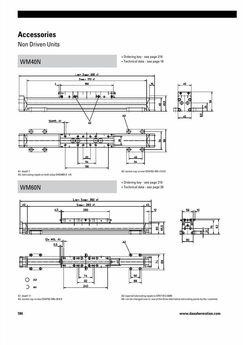
7/23/2019 Linear Actuator Danaher Motion
http://slidepdf.com/reader/full/linear-actuator-danaher-motion 184/224184 www.danahermotion.com
Accessories
Non Driven Units
WM40N
WM60N
A1: depth 7A2: lubricating nipple on both sides DIN3405 D 1/A A3: socket cap screw ISO4762-M5×12 8.8
A1: depth 11A2: socket cap screw ISO4762-M6×20 8.8
A3: tapered lubricating nipple to DIN71412 AM6A4: can be changed over to one of the three alternative lubricating points by the customer
» Ordering key - see page 219» Technical data - see page 18
» Ordering key - see page 219
» Technical data - see page 20

7/23/2019 Linear Actuator Danaher Motion
http://slidepdf.com/reader/full/linear-actuator-danaher-motion 185/224185
Linear Units
www.danahermotion.com
Accessories
Non Driven Units
WM60N with Single Short Carriage
WM80N
A1: depth 11A2: socket cap screw ISO4762-M6×20 8.8 A3: tapered lubricating nipple to DIN71412 AM6A4: can be changed over to one of the three alternative lubricating points by the customer
A1: depth 12A2: socket cap screw ISO4762-M6×20 8.8
A3: tapered lubricating nipple to DIN71412 AM6A4: can be changed over to one of the three alternative lubricating points by the customer
» Ordering key - see page 219» Technical data - see page 22
» Ordering key - see page 219
» Technical data - see page 26

7/23/2019 Linear Actuator Danaher Motion
http://slidepdf.com/reader/full/linear-actuator-danaher-motion 186/224186 www.danahermotion.com
Accessories
Non Driven Units
WM80N with Single Short Carriage
WM120N
A1: depth 12A2: socket cap screw ISO4762-M6×20 8.8 A3: tapered lubricating nipple to DIN71412 AM6A4: can be changed over to one of the three alternative lubricating points by the customer
A1: depth 22A2: socket cap screw ISO4762-M8×20 8.8
A3: tapered lubricating nipple to DIN71412 M8×1A4: can be changed over to one of the three alternative lubricating points by the customer
» Ordering key - see page 219» Technical data - see page 28
» Ordering key - see page 219
» Technical data - see page 30

7/23/2019 Linear Actuator Danaher Motion
http://slidepdf.com/reader/full/linear-actuator-danaher-motion 187/224187
Linear Units
www.danahermotion.com
Accessories
Non Driven Units
M75N
M100N
A1: lubrication holes ø6 (MG07N), ø10 (MF07N)
A2: 150 (MG07N), 100 (MF07N)A3: 24 (MG07N), 43 (MF07N)
A4: 300 (MG07N), 320 (MF07N)
A5: depth 8 Heli coilA6: ø13,5 / ø 8,5 for socket head cap screw M8
A1: lubrication holes ø6 (MG10N), ø10 (MF10N)A2: 100 if L order is equal or < 1 m, 200 if L order > 1 m (MG10N), 265 (MF10N)
A3: 34,5 (MG10N), 56,5 (MF10N)
A4: 100 if L order is equal or < 1 m, 350 if L order > 1 m (MG10N)
265 if L order is equal or > 0,7 m, no hole if L order < 0,7 m (MF10N)A5: depth 10 Heli coil
A6: ø17 / ø 10,5 for socket head cap screw M10
» Ordering key - see page 220» Technical data - see page 56
» Ordering key - see page 220
» Technical data - see page 58

7/23/2019 Linear Actuator Danaher Motion
http://slidepdf.com/reader/full/linear-actuator-danaher-motion 188/224188 www.danahermotion.com
Accessories
Dynamic Servo Actuators
Danaher Motion offers a range of “ready-to-run” linear actuators called Dynamic Servo Ac-
tuators. One part number will include everything: a linear actuator, a gear, a flange, necessary
couplings, a servo motor and a servo drive. All necessary cables, a set of limit switches and
a mounting kit are also included. This will significantly reduce the time spent on engineering,
component selection and comissioning for an application. A free user friendly sizing and selec-
tion software is available to assist you in the process of getting the ultimate package for your
specific application.

7/23/2019 Linear Actuator Danaher Motion
http://slidepdf.com/reader/full/linear-actuator-danaher-motion 189/224189
Linear Units
www.danahermotion.com
Accessories
Multi Axis System Kits
Using the wide range of Danaher Motion linear units it is easy to create complex robots or ma-
nipulators regardless of the application. We can offer solutions for most applications, whether
it is a high-speed short cycle application, a high precision pick and place equipment, hydrau-
lics replacement or a heavy load and long movements application in a harsh environment.
We offer a wide range of brackets and fixation components that enables you to design your
complete linear unit motion system. And together with our Kollmorgen motor and drive pack-
ages we can supply you the complete motion solution. For sizing and selection of a systemplease contact us for more detailed information.

7/23/2019 Linear Actuator Danaher Motion
http://slidepdf.com/reader/full/linear-actuator-danaher-motion 190/224190 www.danahermotion.com

7/23/2019 Linear Actuator Danaher Motion
http://slidepdf.com/reader/full/linear-actuator-danaher-motion 191/224191
Linear Units
www.danahermotion.com
Additional Technical Data
Linear Units with Ball Screw Drive and Ball Guides
Technical Data
Parameter WM40S WM40D WM60D WM60S WM60X WM80D WM80S WM120D
Geometrical moment of
inertia of the profile (ly)
[mm4]10,8 × 10⁴ 10,8 × 10⁴ 5,8 × 10⁵ 5,8 × 10⁵ 5,8 × 10⁵ 1,85 × 10⁶ 1,85 × 10⁶ 7,7 × 10⁶
Geometrical moment of
inertia of the profile (lz)
[mm4]
13,4 × 10⁴ 13,4 × 1045,9 × 105 5,9 × 10⁵ 5,9 × 10⁵ 1,94 × 10⁶ 1,94 × 10⁶ 9,4 × 10⁶
Friction factor of the
guide system (µ)0,05 0,05 0,1 0,1 0,1 0,1 0,1 0,1
Effiency of the unit 0,8 0,8 0,8 0,8 0,8 0,8 0,8 0,8
Bending factor (b) 0,0003 0,0003 0,0003 0,0003 0,0003 0,0003 0,0003 0,0003
Inertia of ball screw (jsp) [kgm2
/m] 1,13 × 10⁻⁵
1,13 × 10⁻⁵
8,46 × 10⁻⁵
8,46 × 10⁻⁵
8,46 × 10⁻⁵
2,25 × 10⁻⁴
2,25 × 10⁻⁴
6,34 × 10⁻⁴
Dynamic load rating of
ball screw (Cx)
05 mm lead
10 mm lead
20 mm lead
40 mm lead
50 mm lead
[N]
4400
-
-
-
-
4400
-
-
-
-
10500
-
11600
-
8400
10500
-
11600
-
8400
10500
-
-
-
-
12300
13200
13000
-
15400
12300
13200
13000
-
15400
21500
33400
29700
14900
-
Dynamic load rating of
ball guide (Cy)
[N]2 × 2650 2 × 2650 4 × 11495 2 × 12964 4 × 11495 4 × 14356 2 × 18723 4 × 18723
Dynamic load rating of
ball guide (Cz)
[N]2 × 3397 2 × 3397 4 × 10581 2 × 11934 4 × 10581 4 × 13739 2 × 17919 4 × 17919
Distance between ball
guide carriages (Lx)
[mm]87 136 141,7 - 141,7 154 - 186
Distance between ballguide carriages (Ly)
[mm] - - 35 35 35 49,75 49,75 80,75
Parameter WV60 WV80 WV120 MLSM60D MLSM80D 2HBE10 2HBE20
Geometrical moment of
inertia of the profile (ly)
[mm4]5,8 × 10⁵ 1,85 × 10⁶ 7,7 × 10⁶ 1,19 × 10⁶ 3,77 × 10⁶ 1,69 × 10⁶ 1,77 × 10⁷
Geometrical moment of
inertia of the profile (lz)
[mm4]5,9 × 10⁵ 1,94 × 10⁶ 9,4 × 10⁶ 1,08 × 10⁷ 4,71 × 10⁷ 1,3 105 5,95 × 10⁵
Friction factor of the
guide system (µ)no guides no guides no guides 0,1 0,1 0,05 0,05
Effiency of the unit 0,8 0,8 0,8 0,8 0,8 0,9 0,9
Bending factor (b) 0,0003 0,0003 0,0003 0,0003 0,0003 0,0003 0,0003
Inertia of ball screw (jsp) [kgm2 /m] 8,46 × 10⁻⁵ 2,25 × 10⁻⁴ 6,34 × 10⁻⁴ 2,25 × 10⁻⁴ 6,34 × 10⁻⁴ 3,67 × 10⁻⁵ 2,28 × 10⁻⁴
Dynamic load rating of
ball screw (Cx)
05 mm lead
10 mm lead
20 mm lead
25 mm lead
40 mm lead
50 mm lead
[N]
10500
-
11600
-
8400
12300
13200
13000
-
15400
21500
33400
29700
14900
-
12300
13200
13000
-
-
15400
21500
33400
29700
-
14900
-
13000
6000
-
-
-
-
18300
22800
-
10000
-
-
Dynamic load rating of
ball guide (Cy)
[N]no guides no guides no guides 4 × 13770 4 × 17965 4 × 2820 4 × 13000
Dynamic load rating of
ball guide (Cz)
[N]no guides no guides no guides 4 × 13770 4 × 17965 4 × 2820 4 × 13000
Distance between ball
guide carriages (Lx)
[mm]no guides no guides no guides 163 185 54 112
Distance between ball
guide carriages (Ly)
[mm]no guides no guides no guides 105 164 70 145

7/23/2019 Linear Actuator Danaher Motion
http://slidepdf.com/reader/full/linear-actuator-danaher-motion 192/224192 www.danahermotion.com
Technical Data
Parameter WB40 WB60 M55 M75 M100 M75D M100D
Geometrical moment of
inertia of the profile (ly)
[mm4]1,04 × 10⁵ 6,1 × 10⁵ 4,27 × 10⁵ 1,9 × 10⁶ 5,54 × 10⁶ 1,9 × 10⁶ 5,54 × 10⁶
Geometrical moment of
inertia of the profile (lz)
[mm4]1,29 × 10⁵ 7,0 × 10⁵ 3,4 × 10⁵ 1,15 × 10⁶ 3,86 × 10⁶ 1,15 × 10⁶ 3,86 × 10⁶
Friction factor of the
guide system (µ)0,3 0,3 0,15 0,15 0,15 0,15 0,15
Effiency
ball nut unit
composite nut unit
0,8
-
0,8
-
0,8
0,5
0,8
0,5
0,8
0,5
0,8
-
0,8
-
Bending factor (b) 0,0005 0,0005 0,0005 0,0005 0,0005 0,0005 0,0005
Inertia of ball screw (jsp) [kgm2 /m] 1,13 × 10⁻⁵ 8,46 × 10⁻⁵ 4,1 × 10⁻⁵ 1,6 × 10⁻⁴ 2,5 × 10⁻⁴ 1,6 × 10⁻⁴ 2,5 × 10⁻⁴
Dynamic load rating of
ball screw (Cx)
05 mm lead
05,8 mm lead
08 mm lead
10 mm lead
12,7 mm lead
20 mm lead
25 mm lead
32 mm lead
[N]
4400
-
-
-
-
-
-
-
10500
-
-
-
-
11600
-
-
4600
5420
-
4200
-
1900
-
2000
10400
-
-
-
17960
10400
-
-
12500
-
-
20600
-
-
11800
-
10400
-
-
-
-
10400
-
-
12500
-
-
20100
-
-
11800
-
Additional Technical Data
Linear Units with Ball Screw and Slide Guides
Technical Data
Parameter WH40 WM60Z WM80Z M55 M75 M100 MLSM80Z
Geometrical moment of
inertia of the profile (ly)
[mm4]12,6 × 10⁴ 5,62 × 10⁵ 1,85 × 10⁶ 4,59 × 10⁵ 1,9 × 10⁶ 5,54 × 10⁶ 3,77 × 10⁶
Geometrical moment of
inertia of the profile (lz)
[mm4]15,3 × 10⁴ 5,94 × 10⁵ 1,94 × 10⁶ 3,56 × 10⁵ 1,15 × 10⁶ 3,86 × 10⁶ 4,71 × 10⁷
Friction factor of the
guide system (µ)0,05 0,1 0,1 0,02 0,02 0,02 0,1
Effiency of the unit 0,85 0,85 0,85 0,95 0,95 0,95 0,85
Bending factor (b) 0,0005 0,0005 0,0005 0,0005 0,0005 0,0005 0,0005
Specific mass of belt [kg/m] 0,032 0,074 0,14 0,09 0,16 0,31 0,517
Inert ia of pulleys (Jsyn) [kgm2] 8,8 × 10⁻⁶ 2,13 × 10⁻⁵ 1,12 × 10⁻⁴ 1,7 × 10⁻⁵ 6,8 × 10⁻⁵ 8,5 × 10⁻⁵ 5,077 × 10-4
Dynamic load rating
of ball guide (Cy)
[N]2 × 2650 2 × 12964
4 × 18723
(2 × 18723)12 × 2717 2 × 8206 2 × 13189 4 × 17965
Dynamic load rating
of ball guide (Cz)
[N]2 × 3397 2 × 11934 2 × 17919 2 × 3484 2 × 15484 2 × 24885 4 × 17965
Distance between ball
guide carriages (Lx)
[mm]72 - - 78 96 140 185
Distance between ball
guide carriages (Ly)
[mm]- 35 49,75 - - - 164
Linear Units with Belt Drive and Ball Guides
1 Value in brackets = for short carriage.
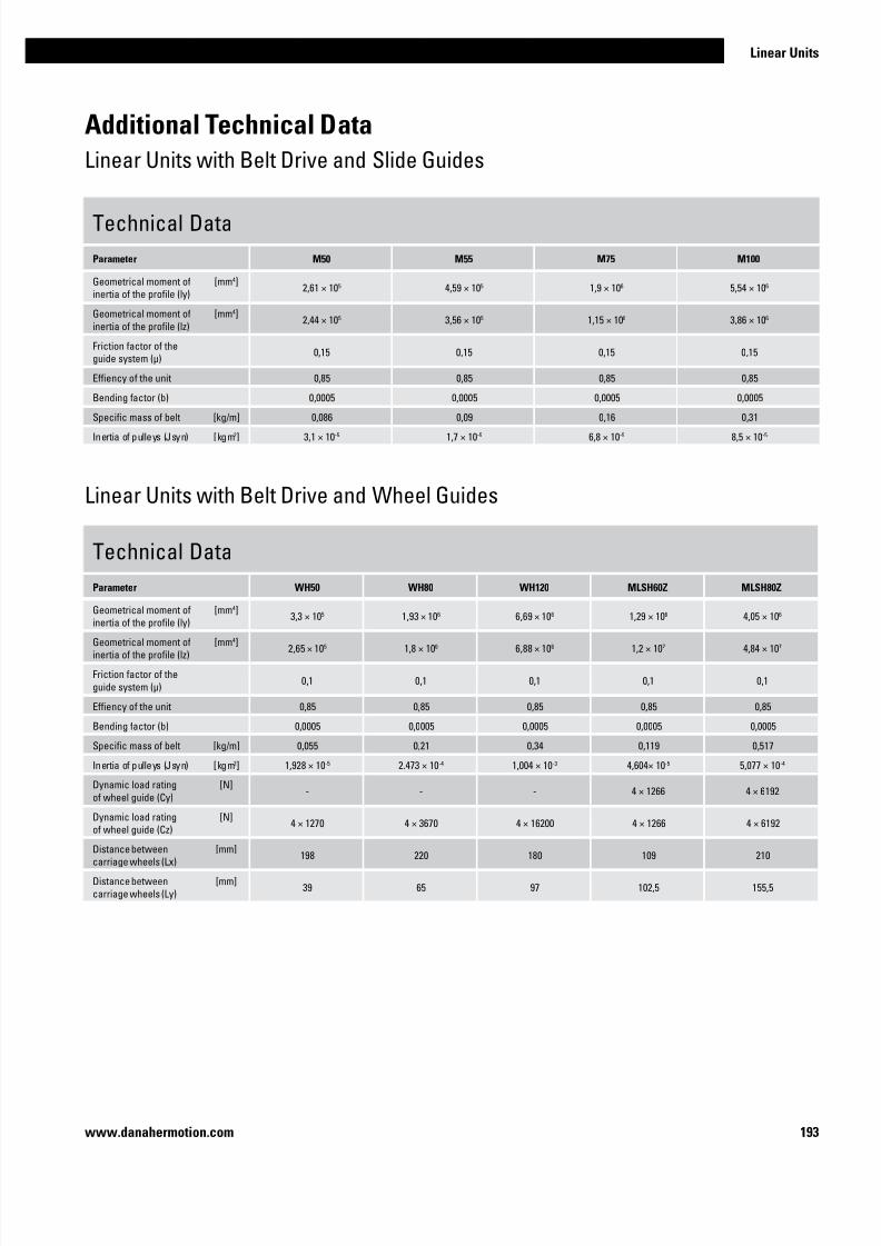
7/23/2019 Linear Actuator Danaher Motion
http://slidepdf.com/reader/full/linear-actuator-danaher-motion 193/224193
Linear Units
www.danahermotion.com
Technical Data
Parameter M50 M55 M75 M100
Geometrical moment of
inertia of the profile (ly)
[mm4]2,61 × 10⁵ 4,59 × 10⁵ 1,9 × 10⁶ 5,54 × 10⁶
Geometrical moment of
inertia of the profile (lz)
[mm4]2,44 × 10⁵ 3,56 × 10⁵ 1,15 × 10⁶ 3,86 × 10⁶
Friction factor of the
guide system (µ)0,15 0,15 0,15 0,15
Effiency of the unit 0,85 0,85 0,85 0,85
Bending factor (b) 0,0005 0,0005 0,0005 0,0005
Specific mass of belt [kg/m] 0,086 0,09 0,16 0,31
Inertia of pulleys (Jsyn) [kgm2] 3,1 × 10⁻⁵ 1,7 × 10⁻⁵ 6,8 × 10⁻⁵ 8,5 × 10⁻⁵
Additional Technical Data
Linear Units with Belt Drive and Slide Guides
Technical Data
Parameter WH50 WH80 WH120 MLSH60Z MLSH80Z
Geometrical moment of
inertia of the profile (ly)
[mm4]3,3 × 10⁵ 1,93 × 10⁶ 6,69 × 10⁶ 1,29 × 10⁶ 4,05 × 10⁶
Geometrical moment of
inertia of the profile (lz)
[mm4]2,65 × 10⁵ 1,8 × 10⁶ 6,88 × 10⁶ 1,2 × 10⁷ 4,84 × 10⁷
Friction factor of the
guide system (µ)0,1 0,1 0,1 0,1 0,1
Effiency of the unit 0,85 0,85 0,85 0,85 0,85
Bending factor (b) 0,0005 0,0005 0,0005 0,0005 0,0005
Specific mass of belt [kg/m] 0,055 0,21 0,34 0,119 0,517
Inertia of pulleys (Jsyn) [kgm2] 1,928 × 10-5 2.473 × 10⁻⁴ 1,004 × 10-3 4,604× 10-5 5,077 × 10-4
Dynamic load rating
of wheel guide (Cy)
[N]- - - 4 × 1266 4 × 6192
Dynamic load rating
of wheel guide (Cz)
[N]4 × 1270 4 × 3670 4 × 16200 4 × 1266 4 × 6192
Distance between
carriage wheels (Lx)
[mm]198 220 180 109 210
Distance between
carriage wheels (Ly)
[mm]39 65 97 102,5 155,5
Linear Units with Belt Drive and Wheel Guides

7/23/2019 Linear Actuator Danaher Motion
http://slidepdf.com/reader/full/linear-actuator-danaher-motion 194/224194 www.danahermotion.com
Technical Data
Parameter WHZ50 WHZ80 Z2 Z3 ZB
Geometrical moment of
inertia of the profile (lx)
[mm4]- - 1,87 × 10⁷ 1,87 × 10⁷ 1,01 × 10⁶
Geometrical moment of
inertia of the profile (ly)
[mm4]3,3 × 10⁵ 1,93 × 10⁶ 2,19 × 10⁷ 2,19 × 10⁷ 1,7 × 10⁶
Geometrical moment of
inertia of the profile (lz)
[mm4]2,65 × 10⁵ 1,8 × 10⁶ - - -
Dynamic load rating of
ball screw (Fx)[N] belt drive belt drive - - -
Dynamic load rating ofball screw (Fz)
ball screw ø 25 lead 10 mm
ball screw ø 25 lead 25 mm
ball screw ø 32 lead 10 mm
[N
21248
11182
47200
21248
11182
47200
belt drive
Friction factor of the
guide system (µ)0,1 0,1 0,15 0,15 0,02
Effiency of the unit 0,85 0,85 0,8 0,8 0,95
Specific mass of belt [kg/m] 0,055 0,119 - - 0,56
Inertia of pulleys (Jsyn) [kgm2] 6,906 × 10-5 5,026 × 10-4 - - 2,73 × 10⁻³
Inertia of ball screw (jsp)
ball screw ø 25 lead 10
ball screw ø 25 lead 25
ball screw ø 32 lead 10
[kgm2 /m]
-
-
-
-
-
-
2,1 × 10⁻⁴
2,6 × 10⁻⁴
6,43 × 10⁻⁴
2,1 × 10⁻⁴
2,6 × 10⁻⁴
6,43 × 10⁻⁴
-
-
-
Dynamic load rating
of ball guide (Cx)
[N]- - slide guide slide guide 13100
Dynamic load rating
of ball guide (Cy)
[N]4 × 1270 4 × 3670 slide guide slide guide 13100
Distance between ball
guide carriages (Lx)
[mm]198 220 - - 20
Distance between ball
guide carriages (Ly)
[mm]39 65 slide guide slide guide 255
Distance between ball
guide carriages (Lz)
[mm]- - slide guide slide guide 255
Definition of forces
Additional Technical Data
Linear Lifting Units

7/23/2019 Linear Actuator Danaher Motion
http://slidepdf.com/reader/full/linear-actuator-danaher-motion 195/224195
Linear Units
www.danahermotion.com
Technical Data
Parameter WZ60 WZ80 T90 T130
Geometrical moment of
inertia of the profile (Iy)
[mm4]5,8 × 10⁵ 1,85 × 10⁶ 3,05 × 10⁶ 1,19 × 10⁷
Geometrical moment of
inertia of the profile (lz)
[mm4]5,9 × 10⁵ 1,94 × 10⁶ 2,91 × 10⁶ 1,23 × 10⁷
Friction factor of the
guide system (µ)0,1 0,1 0,15 0,15
Effiency of the unit 0,8 0,8 0,8 0,8
Inertia of ball screw (jsp)
05 mm lead 10 mm lead
20 mm lead
25 mm lead
32 mm lead
40 mm lead
50 mm lead
[kgm2 /m]
8,46 × 10⁻⁵
-
8,46 × 10⁻⁵
-
-
-
8,46 × 10⁻⁵
2,25 × 10⁻⁴
2,25 × 10⁻⁴
2,25 × 10⁻⁴
-
-
-
2,25 × 10⁻⁴
2,21 × 10⁻⁴
2,1 × 10⁻⁴
2,6 × 10⁻⁴
6,34 × 10⁻⁴
6,34× 10⁻⁴
-
-
-1,45 × 10⁻³
1,45 × 10⁻³
-
-
1,45 × 10⁻³
-
Dynamic load rating of
ball screw (Cx)
05 mm lead
10 mm lead
20 mm lead
25 mm lead
32 mm lead
40 mm lead
50 mm lead
[N]
10500
-
11600
-
-
-
8400
12300
13200
13000
-
-
-
15400
13100
22900
47200
13000
20000
-
-
-
64900
52200
-
-
59700
-
Dynamic load rating
of ball guide (Cy)
[N]2 × 12964 2 × 18723 slide guides slide guides
Dynamic load rating
of ball guide (Cz)
[N]2 × 11943 2 × 17919 slide guides slide guides
Distance between ball
guide carriages (Lx)
[mm]- - slide guides slide guides
Distance between ball
guide carriages (Ly)
[mm]35 50 slide guides slide guides
Dynamic rating of
the ball bushing
[N]8300 13700 slide guides slide guides
Additional Technical Data
Linear Rod Units

7/23/2019 Linear Actuator Danaher Motion
http://slidepdf.com/reader/full/linear-actuator-danaher-motion 196/224196 www.danahermotion.com
Drive Calculations
Screw Driven Units
Feed Force Formula [N]
Fx = m × g × µ
Acceleration Force Formula [N]
Fa = m × a
Power Formula [kW]
P =MA × nmax × 2 × 3,14
60 × 1000
Drive Moment Formulas [Nm]
MA = Mload + M trans + Mrot + M idle
M trans =Fa × p
2 × 3,14 ×1000
Mload =Fx × p
2 × 3,14 ×1000
Mrot = jsp ×2 × 3,14 × nmax × a × 2
Vmax × 60 × 1000
M idle = see table for unit in question
Fx = feed force [N]
m = total mass to be moved [kg] 1
g = acceleration due to gravity [m/s2]
µ = friction factor specific for each unit
Fa = acceleration force [N]
m = mass to be operated [kg]
a = acceleration [m/s2) 2
P = required power [kW]
MA = required drive moment [Nm]
nmax = maximum required rotational speed [rpm]
MA = required drive moment [Nm]
Mload = moment as a result of various loads [N]
Mtrans = translational acceleration moment [Nm]
Mrot = rotational acceleration moment [Nm]
M idle = carriage/rod idle torque [Nm] 3
Fx = feed force [N]
p = screw lead [mm]
Fa = maximum required acceleration force [N]
jsp = inertia of ball screw per meter [kgm2 /m] 4
nmax = maximum required rotational speed [rpm]
a =maximum required acceleration [m/s2)
Vmax = maximum required linear speed [m/s]
1 The total mass is the mass of all masses to be moved (objects to
be moved, carriage(s)/rod, screw).
2 In vertical applications, the mass acceleration must be added to
the acceleration due to gravity g (9,81 m/s2).
3 This value can be found in the carriage idle torque tables for each
unit.
4 This value can be found in the additional technical data tables.

7/23/2019 Linear Actuator Danaher Motion
http://slidepdf.com/reader/full/linear-actuator-danaher-motion 197/224197
Linear Units
www.danahermotion.com
Drive Calculations
Belt Driven Units
Feed Force Formula [N]
Fx = m × g × µ
Acceleration Force Formula [N]
Fa = m × a
Power Formula [kW]
Drive Moment Formulas [Nm]
MA = Mload + M trans + Mrot + M idle
M trans =Fa × do
1000 × 2
Mload =Fx × do
1000 × 2
Mrot = Jsyn ×
2 × 3,14 × nmax
×
a
60 Vmax
M idle = see table for unit in question
P =MA × nmax × 2 × 3,14
60 × 1000
Fx = feed force [N]
m = total mass to be moved [kg] 1
g = acceleration due to gravity [m/s2]
µ = friction factor specific for each unit
Fa = acceleration force [N]
m = mass to be operated [kg]
a = acceleration [m/s2] 2
P = required power [kW]
MA = required drive moment [Nm]
nmax = maximum required rotational speed [rpm]
MA = required drive moment [Nm]
Mload = moment as a result of various loads [N]
Mtrans = translational acceleration moment [Nm]
Mrot = rotational acceleration moment [Nm]
M idle = carriage/rod idle torque [Nm] 3
Fx = feed force [N]
do = pulley diameter [mm] 4
Fa = maximum required acceleration force [N]
Jsyn = idle torque of pulleys [kgm2] 5
nmax = maximum required rotational speed [rpm]
a = maximum required acceleration [m/s2]
Vmax = maximum required linear speed [m/s]
1 The total mass is the mass of all masses to be moved (objects to
be moved, carriage(s)/rod, belt).
2 In vertical applications, the mass acceleration must be added to the acceleration due to gravity g (9,81 m/s2).
3 This value can be found in the carriage idle torque tables.
4 This value can be found in the performance specifications tables
for each unit.
5 This value can be found in the additional technical data tables.

7/23/2019 Linear Actuator Danaher Motion
http://slidepdf.com/reader/full/linear-actuator-danaher-motion 198/224198 www.danahermotion.com
Deflection Calculations
How to calculate the deflection of the profile
Load Cases
Profile supported in both ends.
Profile fixed at both sides.
Profile supported in both ends.
Profile fixed at one side.
1. 2. 3.F FF
Lf
Permissible Profile Deflection Formula [mm]
fh = Lf × b
fh = permissible profile deflection [mm]
Lf = length of profile being bent [mm]
b = bending factor 1
fmax = deflection of the profile [mm]
m’100 = weight of every 100 mm of
stroke [kg] 2
mext = external load on carriage [kg]
mc = weight of carriage(s) [kg] 2
g = acceleration due to gravity [m/s2]
EAl = elastic modulus of aluminium (70000 N/mm2)
Iy = geometrical moment of inertia of
the profile in Y direction [mm4] 1
1 This value can be found in the additional
technical data tables.
2 This value can be found in the performance
specifications tables for each unit.
LfLf
Profile Deflection Formulas [mm]
Load Case 1.
Load Case 2.
Load Case 3.
fmax =m’100 × g × Lf
+(mext × mc) × g × Lf
100 × 384 × EAl × Iy 192 × EAl × Iy
34
fmax =m’100 × g × Lf
+ (mext × mc) × g × Lf
100 × 185 × EAl × Iy 48 × 5 × EAl × Iy
34
Conclusion Formulas
fh > fmax = deflection OK
fh < fmax = deflection not OK, Lf must be shorter
fmax =m’100 × g × Lf
+ (mext × mc) × g × Lf
100 × 8 × EAl × Iy 3 × EAl × Iy
34
Profile supported in one end.
Profile fixed at one side.

7/23/2019 Linear Actuator Danaher Motion
http://slidepdf.com/reader/full/linear-actuator-danaher-motion 199/224199
Linear Units
www.danahermotion.com
Deflection Calculations
Examples of calculations of the profile deflection
Type of linear unit:
WH80
Load case:
Case 1 - profile supported in both ends and
fixed at both sides.
Load to be moved by carriage:mext = 150 kg
Distance between supports:
Lf = 600 mm
Specific unit data:m’100 = 0,93 kg
mc = 2,75 kg
EAl = 70000 N/mm2
Iy = 1,93 × 106 mm4
b = 0,0005
Calculated values:
fh = 0,3 mm
fmax = 0,013 mm
Conclusion:fh > fmax = deflection OK
Example 1 Example 2 Example 3
Type of linear unit:
M55 (MF06B)
Load case:
Case 2 - profile supported in both ends and
fixed at one side.
Load to be moved by carriage:mext = 100 kg
Distance between supports:
Lf = 600 mm
Specific unit data:m’100 = 0,53 kg
mc = 1,2 kg
EAl = 70000 N/mm2
Iy = 4,59 × 105 mm4
b = 0,0005
Calculated values:
fh = 0,3 mm
fmax = 0,063 mm
Conclusion:fh > fmax = deflection OK
Type of linear unit:
WM80
Load case:
Case 3 - profile supported and fixed at one
end.
Load to be moved by carriage:mext = 120 kg
Distance between supports:
Lf = 400 mm
Specific unit data:m’100 = 1,08 kg
mc = 4,26 kg
EAl = 70000 N/mm2
Iy = 1,85 × 106 mm4
b = 0,0003
Calculated values:
fh = 0,12 mm
fmax = 0,203 mm
Conclusion:fh > fmax = deflection not OK

7/23/2019 Linear Actuator Danaher Motion
http://slidepdf.com/reader/full/linear-actuator-danaher-motion 200/224200 www.danahermotion.com

7/23/2019 Linear Actuator Danaher Motion
http://slidepdf.com/reader/full/linear-actuator-danaher-motion 201/224201
Linear Units
www.danahermotion.com
Ordering
How to Order
When ordering a Danaher Motion linear unit it is necessary to first make sure that the proper
sizing and selection has been done. The demand on your system will impact on your choice of
stroke length, profile size, belt or screw drive, environmental protection demands etc.
The load and speed demand will tell you the configuration of gearboxes drive shafts and motor
attachment accessories that are necessary. You will also need to evaluate what accessories
that are necessary, such as mounting brackets, gearboxes, switches, sensors and feedbackdevices.
We will assist you in the sizing and selection work and determining of part numbers but it is
important that you are aware of the demand and need of your specific application in order to
enable us to supply you with the correct linear unit.
On the following pages you will find the ordering keys for the different linear units shown
in earlier chapters. These keys are self-explanatory and by following the examples you can
quickly and easily learn about the different options and versions available. Please also visit
www.danahermotion.com/PosSlides_LinUnits_advisor where you can find a product advisor
that makes the selection and ordering process much easier or contact us for further support.
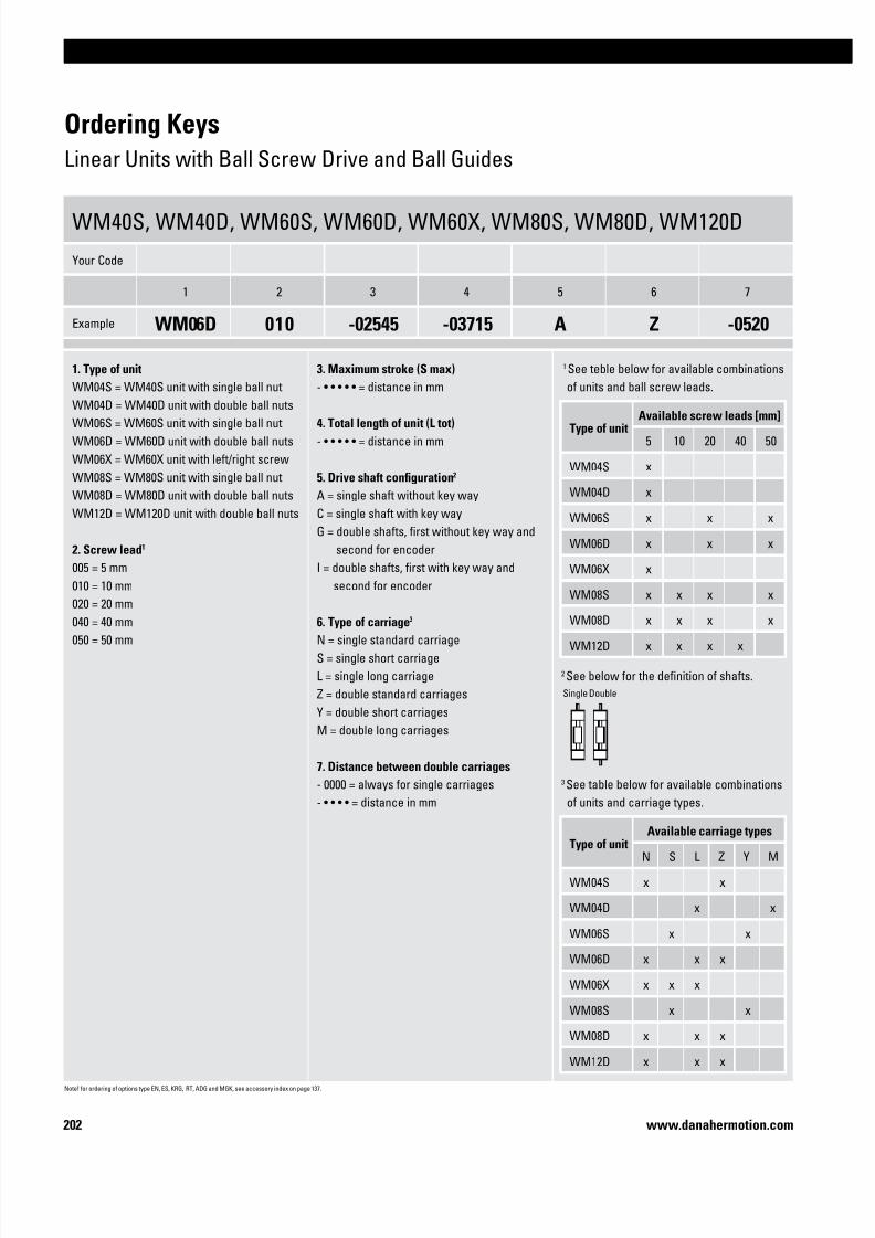
7/23/2019 Linear Actuator Danaher Motion
http://slidepdf.com/reader/full/linear-actuator-danaher-motion 202/224202 www.danahermotion.com
Ordering Keys
Linear Units with Ball Screw Drive and Ball Guides
WM40S, WM40D, WM60S, WM60D, WM60X, WM80S, WM80D, WM120D
Your Code
1 2 3 4 5 6 7
Example WM06D 010 -02545 -03715 A Z -0520
1. Type of unit
WM04S = WM40S unit with single ball nut
WM04D = WM40D unit with double ball nuts
WM06S = WM60S unit with single ball nut
WM06D = WM60D unit with double ball nuts
WM06X = WM60X unit with left/right screw
WM08S = WM80S unit with single ball nut
WM08D = WM80D unit with double ball nuts
WM12D = WM120D unit with double ball nuts
2. Screw lead1
005 = 5 mm
010 = 10 mm
020 = 20 mm
040 = 40 mm
050 = 50 mm
3. Maximum stroke (S max)
- • • • • • = distance in mm
4. Total length of unit (L tot)
- • • • • • = distance in mm
5. Drive shaft configuration2
A = single shaft without key way
C = single shaft with key way
G = double shafts, first without key way and
second for encoder
I = double shafts, first with key way and
second for encoder
6. Type of carriage3
N = single standard carriage
S = single short carriage
L = single long carriage
Z = double standard carriages
Y = double short carriages
M = double long carriages
7. Distance between double carriages
- 0000 = always for single carriages
- • • • • = distance in mm
1 See teble below for available combinations
of units and ball screw leads.
2 See below for the definition of shafts.
3 See table below for available combinations
of units and carriage types.
Type of unitAvailable screw leads [mm]
5 10 20 40 50
WM04S x
WM04D x
WM06S x x x
WM06D x x x
WM06X x
WM08S x x x x
WM08D x x x x
WM12D x x x x
Type of unitAvailable carriage types
N S L Z Y M
WM04S x x
WM04D x x
WM06S x x
WM06D x x x
WM06X x x x
WM08S x x
WM08D x x x
WM12D x x x
Single Double
Note! for ordering of options type EN, ES, KRG, RT, ADG and MGK, see accessory index on page 137.

7/23/2019 Linear Actuator Danaher Motion
http://slidepdf.com/reader/full/linear-actuator-danaher-motion 203/224203
Linear Units
www.danahermotion.com
Ordering Keys
Linear Units with Ball Screw Drive and Ball Guides
WV60, WV80, WV120
Your Code
1 2 3 4 5 6 7
Example WV08D 020 -02745 -03295 G N -0000
1. Type of unit
WV06D = WV60 unit
WV08D = WV60 unit
WV12D = WV120 unit
2. Ball screw lead1
005 = 5 mm
010 = 10 mm
020 = 20 mm
040 = 40 mm
050 = 50 mm
3. Maximum stroke (S max)
- • • • • •= distance in mm
4. Total length of unit (L tot)
- • • • • •= distance in mm
5. Drive shaft configuration2
A = single shaft without key way
C = single shaft with key way
G = double shafts, first without key way and
second for encoder
I = double shafts, first with key way and
second for encoder
6. Type of carriageN = single standard carriage
7. Distance between double carriages
- 0000 = always for single carriages
1 See table below for available combinations
of units and ball screw leads.
2 See below for the definition of shafts.
Type of unitAvailable screw leads [mm]
5 10 20 40 50
WV60 x x x
WV80 x x x x
WV120 x x x x
Single Double
Note! for ordering of options type EN, ES, KRG, RT, ADG and MGK, see accessory index on page 137.

7/23/2019 Linear Actuator Danaher Motion
http://slidepdf.com/reader/full/linear-actuator-danaher-motion 204/224204 www.danahermotion.com
MLSM60D, MLSM80D
Your Code
1 2 3 4 5 6 7
Example MLSM06D 020 -03800 -04645 C L -0000
1. Type of unit
MLSM06D = MLSM60 unit
MLSM08D = MLSM80 unit
2. Ball screw lead
005 = 5 mm
010 = 10 mm
020 = 20 mm
040 = 40 mm
050 = 50 mm
3. Maximum stroke (S max)
- • • • • • = distance in mm
4. Total length of unit (L tot)- • • • • • = distance in mm
5. Drive shaft configuration2
A = single shaft without key way
C = single shaft with key way
G = double shafts, first without key way and
second for encoder
I = double shafts, first with key way and
second for encoder
6. Carriage configuration
N = single standard carriage
L = single long carriage
Z = double standard carriages
7. Distance between double carriages
- 0000 = always for single carriages
- • • • • = distance in mm
1 See table below for available combinations
of units and ball screw leads.
2 See below for the definition of shafts.
Single Double
Ordering Keys
Linear Units with Ball Screw Drive and Ball Guides
Type of unitAvailable screw leads [mm]
5 10 20 40 50
MLSM06D x x x
MLSM08D x x x x

7/23/2019 Linear Actuator Danaher Motion
http://slidepdf.com/reader/full/linear-actuator-danaher-motion 205/224205
Linear Units
www.danahermotion.com
2HBE10, 2HBE20
Your Code
1 2 3 4 5
Example 2HBE10-YP H -N - L0525
1. Type of unit
2HBE10-YP = 2HBE10 unit
2HBE20-YP = 2HBE20 unit
2. Ball screw diameter and lead1
G = 16 mm, 5 mm
H = 16 mm,10 mm
L = 25 mm, 5 mm
M = 25 mm, 10 mm
N = 25 mm, 25 mm
W = non driven unit
3. Drive shaft configuration
-N = NEMA configuration
4. Options
- = no option
B = bellows (reduces stroke by app. 28 %).
S = shrouds
5. Ordering length (L order)
L • • • • = distance in mm
1 See table below for available combinations of units and ball screw
diameters and leads.
Type of unitAvailable ball screw diameter and lead combinations
G H L M N W
2HBE10 x x x
2HBE20 x x x x
Ordering Keys
Linear Units with Ball Screw Drive and Ball Guides

7/23/2019 Linear Actuator Danaher Motion
http://slidepdf.com/reader/full/linear-actuator-danaher-motion 206/224206 www.danahermotion.com
Ordering Keys
Linear Units with Ball Screw Drive and Slide Guides
WB40, WB60
Your Code
1 2 3 4 5 6 7
Example WB40S 020 -00500 -00700 C N 0
1. Type of unit
WB04S = WB40 unit with ball screw
WB04T = WB40 unit with lead screw
WB06S = WB60 unit with ball screw
WB06T = WB60 unit with lead screw
2. Screw lead and screw type1
004 = 4 mm, lead screw
005 = 5 mm, ball screw
008 = 8 mm, lead screw
020 = 20 mm, ball screw
3. Maximum stroke (S max)
- • • • • • = distance in mm
4. Total length of unit (L tot)
- • • • • • = distance in mm
5. Drive shaft configuration2
A = single shaft without key way
C = single shaft with key way
G = double shafts, first without key way and
second for encoder
I = double shafts, first with key way and
second for encoder
6. Carriage configuration
N = single standard carriage
7. Number of screw supports3
0 = no screw supports
1 = one pair of screw supports
2 = two pairs of screw supports3 = three pairs of screw support
1 See table below for available combinations
of units and screw leads.
2 Se below for the definition of shafts.
3 WB40 units can not have any screw
supports at all (allways 0 in this position)
while WB60 can have any of the stated
possibilities.
Single Double
Type of unit Available screw leads [mm]
4 5 8 20
WB04S x
WB04T x x
WB06S x x
WB06T x

7/23/2019 Linear Actuator Danaher Motion
http://slidepdf.com/reader/full/linear-actuator-danaher-motion 207/224207
Linear Units
www.danahermotion.com
M55, M75, M100
Your Code
1 2 3 4 5 6 7
Example MG07 K057 C 10 S 305 S1
1. Type of unit
MG06 = M55 unit
MG07 = M75 unit
MG10 = M100 unit
2. Ball screw type, lead and tolerance class2
C057 = composite nut, 5 mm, T7
K057 = ball nut, 5 mm, T7
KU57 = ball nut, 5,08 mm, T7
C109 = composite nut, 10 mm, T9
K107 = ball nut, 10 mm, T7
K109 = ball nut, 10 mm, T9
K129 = ball nut, 12,7 mm, T9
K207 = ball nut, 20 mm, T7
C257 = composite nut, 25 mm, T7K257 = ball nut, 25 mm, T7
K259 = ball nut, 25 mm, T9
C329 = composite nut, 32 mm, T9
3. Type of carriages
A = single standard carriage
C = double standard carriages
4. Distance between carriages (Lc)
00 = for all single standard carriage units
• • = distance in cm between carriages
5. Screw supports
X = no screw supports
S = single screw supports
D = double screw supports
6. Ordering length (L order)
• • • = distance in cm
7. Protection option1
S1 = S1 wash down protection
1 Leave position blank if no additional protec-
tion is required.2 See table below for available combinations of
units and ball screw type, lead and tolerance.
Ordering Keys
Linear Units with Ball Screw Drive and Slide Guides
Ballscrew type
Type of unit
M55 M75 M100
C057 x
K057 x x x
KU57 x
C109 x
K107 x x
K109 x
K129 x
K207 x x
C257 x
K257 x
K259 x
C329 x

7/23/2019 Linear Actuator Danaher Motion
http://slidepdf.com/reader/full/linear-actuator-danaher-motion 208/224208 www.danahermotion.com
M75D, M100D
Your Code
1 2 3 4 5 6 7
Example MG10 D109 A 00 X 355
1. Type of unit
MG07 = M75D unit
MG10 = M100D unit
2. Ball screw type, lead and tolerance class2
D057 = double ball nut, 5 mm, T7
D107 = double ball nut, 10 mm, T7
D109 = double ball nut, 10 mm, T9
D129 = double ball nut, 12,7 mm, T9
D207 = double ball nut, 20 mm, T7
D257 = double ball nut, 25 mm, T7
3. Type of carriages
A = single standard carriage
C = double standard carriages
4. Distance between carriages (Lc)
00 = for all single standard carriage units
• • = distance in cm between carriages
5. Screw supports
X = no screw supports
S = single screw supports
D = double screw supports
6. Ordering length (L order)
• • • = distance in cm
7. Protection option1
S1 = S1 wash down protection
1 Leave position blank if no protection option
required.2 See below table for available combinations of
units and ball screw type, lead and tolerance.
Ordering Keys
Linear Units with Ball Screw Drive and Slide Guides
Ballscrew type
Type of unit
M75 M100
D057 x x
D107 x
D109 x
D129 x
D207 x
D257 x

7/23/2019 Linear Actuator Danaher Motion
http://slidepdf.com/reader/full/linear-actuator-danaher-motion 209/224209
Linear Units
www.danahermotion.com
Ordering Keys
Linear Units with Belt Drive and Ball Guides
WH40
Your Code
1 2 3 4 5 6
Example WH04Z100 -01400 -01755 H L -0400
1. Type of unit
WH04Z100 = WH40 unit
2. Maximum stroke (S max)
- • • • • • = distance in mm
3. Total length of unit (L tot)
- • • • • • = distance in mm
4. Drive shaft configuration1
A = shaft on left side without key way
B = shaft on right side without key way
C = shaft on left side with key way
D = shaft on right side with key way
E = shaft on left side without key way and
shaft on right side with key way
F = shaft on left side with key way and
shaft on right side without key way
G = shaft on left side without key way and
shaft on right side for encoder
H = shaft on left side for encoder and
shaft on right side without key way
I = shaft on left side with key way and
shaft on right side for encoder
J = shaft on left side for encoder and
shaft on right side with key way
L = shaft on both sides without key way
M = shaft on both sides with key way
W = hollow shaft on both sides with clampingunit
5. Carriage configuration
N = single standard carriage
L = single long carriage
Z = double standard carriages
6. Distance between double carriages
- 0000 = always for single carriages
- • • • • = distance in mm
1 See below for the definition of shafts.
Left Right Both
Note! for ordering of options type EN, ES, KRG, RT, ADG and MGK, see accessory index on page 137.

7/23/2019 Linear Actuator Danaher Motion
http://slidepdf.com/reader/full/linear-actuator-danaher-motion 210/224210 www.danahermotion.com
Ordering Keys
Linear Units with Belt Drive and Ball Guides
WM60Z, WM80Z
Your Code
1 2 3 4 5 6
Example WM08Z170 -02545 -03715 D L -0000
1. Type of unit
WM06Z120 = WM60Z unit
WM08Z170 = WM80Z unit
2. Maximum stroke (S max)
- • • • • • = distance in mm
3. Total length of unit (L tot)
- • • • • • = distance in mm
4. Drive shaft configuration1
A = shaft on left side without key way
B = shaft on right side without key way
C = shaft on left side with key way
D = shaft on right side with key wayE = shaft on left side without key way and
shaft on right side with key way
F = shaft on left side with key way and
shaft on right side without key way
G = shaft on left side without key way and
shaft on right side for encoder
H = shaft on left side for encoder and
shaft on right side without key way
I = shaft on left side with key way and
shaft on right side for encoder
J = shaft on left side for encoder and
shaft on right side with key way
L = shaft on both sides without key way
M = shaft on both sides with key way
V = hollow shaft on both sides for Micron
DT/DTR planetary gear option
5. Carriage configuration2
N = single standard carriage
S = single short carriage
L = single long carriageZ = double standard carriages
Y = double short carriages
6. Distance between double carriages
- 0000 = always for single carriages
- • • • • = distance in mm
1 See below for the definition of shafts.
2 See table below for available combinations
of units and carriage types.
Left Right Both
Type of unitAvailable carriage types
N S L Z Y
WM06Z x x
WM08Z x x x x x

7/23/2019 Linear Actuator Danaher Motion
http://slidepdf.com/reader/full/linear-actuator-danaher-motion 211/224211
Linear Units
www.danahermotion.com
M55, M75, M100
Your Code
1 2 3 4 5 6
Example MF06B105 A 00 X 450 S1
1. Type of unit
MF06B105 = M55 unit
MF07B130 = M75 unit
MF10B176 = M100 unit
2. Type of carriages
A = single standard carriage
C = double standard carriages
3. Distance between carriages (Lc)
00 = for all single standard carriage units
• • = distance in cm between carriages
4. Drive shaft configuration
R = shaft on the side as shown in picture
Q = shaft on the side as shown in picture
X = shaft on both sides
5. Ordering length (L order)
• • • = distance in cm
6. Protection option1
S1 = S1 wash down protection
1 Leave blank if no protection option required.
R Q X
Ordering Keys
Linear Units with Belt Drive and Ball Guides

7/23/2019 Linear Actuator Danaher Motion
http://slidepdf.com/reader/full/linear-actuator-danaher-motion 212/224212 www.danahermotion.com
Ordering Keys
Linear Units with Belt Drive and Ball Guides
MLSM80Z
Your Code
1 2 3 4 5 6
Example MLSM08Z200 -05000 -05570 A N -0000
1. Type of unit
MLSM08Z200 = MLSM80 unit
2. Maximum stroke (S max)
- • • • • • = distance in mm
3. Total length of unit (L tot)
- • • • • • = distance in mm
4. Drive shaft configuration1
A = shaft on left side without key way
B = shaft on right side without key way
C = shaft on left side with key way
D = shaft on right side with key way
E = shaft on left side without key way and
shaft on right side with key way
F = shaft on left side with key way and
shaft on right side without key way
G = shaft on left side without key way and
shaft on right side for encoder
H = shaft on left side for encoder and
shaft on right side without key way
I = shaft on left side with key way and
shaft on right side for encoderJ = shaft on left side for encoder and
shaft on right side with key way
L = shaft on both sides without key way
M = shaft on both sides with key way
5. Carriage configuration
N = single standard carriage
L = single long carriage
Z = double standard carriages
6. Distance between double carriages
- 0000 = always for single carriages
- • • • • = distance in mm
1 See below for the definition of shafts.
Left Right Both

7/23/2019 Linear Actuator Danaher Motion
http://slidepdf.com/reader/full/linear-actuator-danaher-motion 213/224213
Linear Units
www.danahermotion.com
Ordering Keys
Linear Units with Belt Drive and Slide Guides
M50
Your Code
1 2 3 4
Example MG05B130 A00 R 560
1. Type of unit
MG05B130 = M50 unit
2. Type of carriage
A00 = single standard carriage
3. Drive shaft configuration
R = shaft on the side as shown in picture
Q = shaft on the side as shown in picture
X = shaft on both sides
4. Ordering length (L order)
• • • = distance in cm
M55, M75, M100
Your Code
1 2 3 4 5 6
Example MG06B105 A 00 X 450 S2
1. Type of unit
MG06B105 = M55 unit
MG07B130 = M75 unit
MG10B176 = M100 unit
2. Type of carriages
A = single standard carriage
C = double standard carriages
3. Distance between carriages (Lc)
00 = for all single standard carriage units
• • = distance in cm between carriages
4. Drive shaft configuration
R = shaft on the side as shown in picture
Q = shaft on the side as shown in picture
X = shaft on both sides
5. Ordering length (L order)
• • • = distance in cm
6. Protection option1
S1 = S1 wash down protection
S2 = S2 chemical protection
1 Leave blank if no protection option required.
R Q X
R Q X

7/23/2019 Linear Actuator Danaher Motion
http://slidepdf.com/reader/full/linear-actuator-danaher-motion 214/224214 www.danahermotion.com
Ordering Keys
Linear Units with Belt Drive and Wheel Guides
WH50, WH80, WH120
Your Code
1 2 3 4 5 6
Example WH08Z200 -02300 -02710 J L -0000
1. Type of unit
WH05Z120 = WH50 unit
WH08Z200 = WH80 unit
WH12Z260 = WH120 unit
2. Maximum stroke (S max)
- • • • • • = distance in mm
3. Total length of unit (L tot)
- • • • • • = distance in mm
4. Drive shaft configuration1
A = shaft on left side without key way
B = shaft on right side without key way
C = shaft on left side with key way
D = shaft on right side with key way
E = shaft on left side without key way and
shaft on right side with key way
F = shaft on left side with key way and
shaft on right side without key way
G = shaft on left side without key way and
shaft on right side for encoder
H = shaft on left side for encoder and
shaft on right side without key way
I = shaft on left side with key way and
shaft on right side for encoderJ = shaft on left side for encoder and
shaft on right side with key way
K = hollow shaft on both sides without
clamping unit
L = shaft on both sides without key way
M = shaft on both sides with key way
V = hollow shaft on both sides for Micron
DT/DTR planetary gear option
W = hollow shaft on both sides with clamping
unit
5. Carriage configuration
N = single standard carriage
L = single long carriage
Z = double standard carriages
6. Distance between double carriages
- 0000 = always for single carriages
- • • • • = distance in mm
1 See below for the definition of shafts.
Left Right Both
Note! for ordering of options type EN, ES, KRG, RT, ADG and MGK, see accessory index on page 137.

7/23/2019 Linear Actuator Danaher Motion
http://slidepdf.com/reader/full/linear-actuator-danaher-motion 215/224215
Linear Units
www.danahermotion.com
MLSH60Z, MLSH80Z
Your Code
1 2 3 4 5 6
Example MLSH06Z135 -04500 -05580 D Z -0600
1. Type of unit
MLSH06Z135 = MLSH60 unit
MLSH08Z200 = MLSH80 unit
2. Maximum stroke (S max)
- • • • • • = distance in mm
3. Total length of unit (L tot)
- • • • • • = distance in mm
4. Drive shaft configuration1
A = shaft on left side without key way
B = shaft on right side without key way
C = shaft on left side with key way
D = shaft on right side with key way
E = shaft on left side without key way and
shaft on right side with key way
F = shaft on left side with key way and
shaft on right side without key way
G = shaft on left side without key way and
shaft on right side for encoder
H = shaft on left side for encoder and
shaft on right side without key way
I = shaft on left side with key way and
shaft on right side for encoderJ = shaft on left side for encoder and
shaft on right side with key way
L = shaft on both sides without key way
M = shaft on both sides with key way
5. Carriage configuration
N = single standard carriage
L = single long carriage
Z = double standard carriages
6. Distance between double carriages
- 0000 = always for single carriages
- • • • • = distance in mm
1 See below for the definition of shafts.
Left Right Both
Ordering Keys
Linear Units with Belt Drive and Wheel Guides

7/23/2019 Linear Actuator Danaher Motion
http://slidepdf.com/reader/full/linear-actuator-danaher-motion 216/224216 www.danahermotion.com
Ordering Keys
Linear Lifting Units
WHZ50, WHZ80
Your Code
1 2 3 4 5 6
Example WHZ08Z200 -01000 -01410 A N -0000
Z2, Z3Your Code
1 2 3 4
Example MGZ3K 25259 250 450
1. Type of unit
MGZ2K = Z2 unit
MGZ3K = Z3 unit
2. Ball screw diameter, lead and tolerance class
25109 = 25 mm, 10 mm, T9
25259 = 25 mm, 25 mm, T9
32207 = 32 mm, 20 mm, T7
3. Minimum retracted length (L min)
• • • = distance in cm
4. Maximum extended length (L max)
• • • = distance in cm
1. Type of unit
WHZ05Z120 = WHZ50 unit
WHZ08Z200 = WHZ80 unit
2. Maximum stroke (S max)
- • • • • • = distance in mm
3. Total length of unit (L tot)
- • • • • • = distance in mm
4. Drive shaft configuration1
A = shaft on left side without key way
B = shaft on right side without key way
C = shaft on left side with key way
D = shaft on right side with key way
E = shaft on left side without key way and
shaft on right side with key way
F = shaft on left side with key way and
shaft on right side without key way
G = shaft on left side without key way and
shaft on right side for encoder
H = shaft on left side for encoder and
shaft on right side without key way
I = shaft on left side with key way and
shaft on right side for encoderJ = shaft on left side for encoder and
shaft on right side with key way
L = shaft on both sides without key way
M = shaft on both sides with key way
V = hollow shaft on both sides for Micron
DT/DTR planetary gear option
W = hollow shaft on both sides with clamping
unit
5. Carriage configuration
N = single standard carriage
L = single long carriage
Z = double standard carriages
6. Distance between double carriages
- 0000 = always for single carriages
- • • • • = distance in mm
1 See below for the definition of shafts and up
and down.
Left Right Both
Note! for ordering of options type EN, ES, KRG, RT, ADG and MGK, see accessory index on page 137.
Up
Down

7/23/2019 Linear Actuator Danaher Motion
http://slidepdf.com/reader/full/linear-actuator-danaher-motion 217/224217
Linear Units
www.danahermotion.com
ZB
Your Code
1 2 3
Example MF-ZB200A00 X 150
1. Type of unit
MF-ZB200A00 = ZB unit
2. Drive shaft configuration
R = shaft on the side as shown in picture
Q = shaft on the side as shown in picture
X = shaft on both sides
3. Ordering length (L order)
• • • = distance in cm
Ordering Keys
Linear Lifting Units
R Q X

7/23/2019 Linear Actuator Danaher Motion
http://slidepdf.com/reader/full/linear-actuator-danaher-motion 218/224218 www.danahermotion.com
Ordering Keys
Linear Rod Units
WZ60, WZ80
Your Code
1 2 3 4 5 6
Example WZ06S 20 -00350 -00780 C N
1. Type of unit
WZ06 = WZ60 unit
WZ08 = WZ80 unit
2. Ball screw lead
05 = 5 mm
10 = 10 mm
20 = 20 mm
50 = 50 mm
3. Maximum stroke (S max)
- • • • • • = distance in mm
4. Total length of unit (L tot)
- • • • • = distance in mm
5. Drive shaft configuration
A = shaft without key way
C = shaft with key way
6. Extension tube configuration
N = standard
1 See table below for available combinations
of units and screw leads.
T90, T130
Your Code
1 2 3 4 5 6
Example T09-B 2525 M P 450 S1
1. Type of unit
T09-B = T90 unit
T13-B = T130 unit
2. Ball screw diameter, lead and tolerance class
2505 = 25 mm, 05 mm, T7 (only possible for T09-B)
2510 = 25 mm, 10 mm, T7 (only possible for T09-B)
2525 = 25 mm, 25 mm, T7 (only possible for T09-B)
3220 = 32 mm, 20 mm, T7 (only possible for T09-B)
3232 = 32 mm, 32 mm, T7 (only possible for T09-B)
4010 = 40 mm, 10 mm, T7 (only possible for T13-B)
4020 = 40 mm, 20 mm, T7 (only possible for T13-B)
4040 = 40 mm, 40 mm, T7 (only possible for T13-B)
3. Engineering unit
M = metric
4. Type of adapter
N = M16 × 1,5 outside thread (only possible for T09-B25 • •)
P = M16 × 2 inside thread (only possible for T09-B25 • •)
Q = M20 × 1,5 outside thread (only possible for T09-B32 • •)R = M20 × 1,5 inside thread (only possible for T09-B32 • •)
S = M27 × 2 outside thread (only possible for T13-B • •)
T = M27 × 2 inside thread (only possible for T13-B • •)
U = M33 × 2 outside thread (only possible for T13-B • •)
V = M33 × 2 inside thread (only possible for T13-B • •)
X = M30 × 2 inside thread (only possible for T13-B • •)
5. Ordering length (L order)
• • • = distance in cm
6. Protection option1
S1 = wash down protection
1 Leave blank if no protection option required.
Note! for ordering of options type EN, ES, KRG, RT and MGK, see accessory index on page 137.
Type of unitAvailable screw leads [mm]
5 10 20 50
WZ06 x x x
WZ08 x x x x

7/23/2019 Linear Actuator Danaher Motion
http://slidepdf.com/reader/full/linear-actuator-danaher-motion 219/224219
Linear Units
www.danahermotion.com
Ordering Keys
Non driven Units
WH40N, WH50N, WH80N, WH120N
Your Code
1 2 3 4 5 6
Example WH04N000 -04500 -04640 K N -0000
1. Type of unit
WH04N000 = WH40N unit
WH05N000 = WH50N unit
WH08N000 = WH80N unit
WH12N000 = WH120N unit
2. Maximum stroke (S max)
- • • • • • = distance in mm
3. Total length of unit (L tot)
- • • • • • = distance in mm
4. Drive shaft configuration1
K = no shaft
5. Carriage configuration
N = single standard carriage
L = single long carriage
Z = double standard carriages
6. Distance between double carriages
- 0000 = always for single carriages
- • • • • = distance in mm
WM40N, WM60N, WM80N, WM120N
Your Code
1 2 3 4 5 6
Example WM08N000 -07010 -07210 K N -0000
1. Type of unit
WM04N000 = WM40N unit
WM06N000 = WM60N unit
WM08N000 = WM80N unit
WM12N000 = WM120N unit
2. Maximum stroke (S max)
- • • • • • = distance in mm
3. Total length of unit (L tot)
- • • • • • = distance in mm
4. Drive shaft configuration
K = no shaft
5. Type of carriage1
N = single standard carriage
S = single short carriage
L = single long carriage
Z = double standard carriages
Y = double short carriages
6. Distance between double carriages
- 0000 = always for single carriages
- • • • • = distance in mm
1 See table below for available combinations
of units and carriage types.
Type of unitAvailable carriage types
N S L Z Y
WM04N000 x x x
WM06N000 x x x x x
WM08N000 x x x x x
WM12N000 x x x
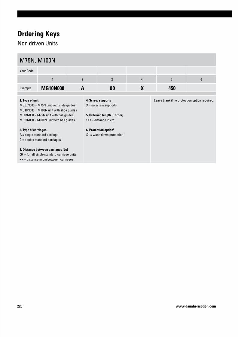
7/23/2019 Linear Actuator Danaher Motion
http://slidepdf.com/reader/full/linear-actuator-danaher-motion 220/224220 www.danahermotion.com
Ordering Keys
Non driven Units
M75N, M100N
Your Code
1 2 3 4 5 6
Example MG10N000 A 00 X 450
1. Type of unit
MG07N000 = M75N unit with slide guides
MG10N000 = M100N unit with slide guides
MF07N000 = M75N unit with ball guides
MF10N000 = M100N unit with ball guides
2. Type of carriages
A = single standard carriage
C = double standard carriages
3. Distance between carriages (Lc)
00 = for all single standard carriage units
• • = distance in cm between carriages
4. Screw supports
X = no screw supports
5. Ordering length (L order)
• • • = distance in cm
6. Protection option1
S1 = wash down protection
1 Leave blank if no protection option required.
7/23/2019 Linear Actuator Danaher Motion
http://slidepdf.com/reader/full/linear-actuator-danaher-motion 221/224221
Linear Units
www.danahermotion.com
– Page intentionally left blank –

7/23/2019 Linear Actuator Danaher Motion
http://slidepdf.com/reader/full/linear-actuator-danaher-motion 222/224222 www.danahermotion.com
– Page intentionally left blank –

7/23/2019 Linear Actuator Danaher Motion
http://slidepdf.com/reader/full/linear-actuator-danaher-motion 223/224

7/23/2019 Linear Actuator Danaher Motion
http://slidepdf.com/reader/full/linear-actuator-danaher-motion 224/224
United KingdomDanaher Motion
Chartmoor Road, Chartwell Business Park
Leighton Buzzard, Bedfordshire
LU7 4WG; United KingdomPhone : +44 (0)1525 243 243
Fax : +44 (0)1525 243 244
E-mail : [email protected]
GermanyDanaher Motion GmbH
Sales Office North
Wacholderstr. 40-42
40489 Düsseldorf
SwedenDanaher Motion
Box 9053
291 09 Kristianstad
SwedenPhone : +46 (0) 44-24 67 00
Fax : +46 (0) 44-24 40 85
E-mail : [email protected]
SwitzerlandDanaher Motion SA
La Pierreire 2
1029 Villars-Ste-Croix
Switzerland