Linac4 Low Level RF
20
Jan 30, 2008 MAC meeting 1 Linac4 Low Level RF P. Baudrenghien with help from J. Molendijk CERN AB-RF
description
Linac4 Low Level RF. P. Baudrenghien with help from J. Molendijk. CERN AB-RF. Outline. 1. Tank Controller Functionalities Developments Block Diagram Platform Diagnostics Implementation Example of VME cards 2. Reference Clock 3. Open Questions Klystron power margin - PowerPoint PPT Presentation
Transcript of Linac4 Low Level RF
Jan 30, 2008 MAC meeting 1
Linac4 Low Level RF
P. Baudrenghien
with help from J. Molendijk
CERN AB-RF
Jan 30, 2008 MAC meeting 2
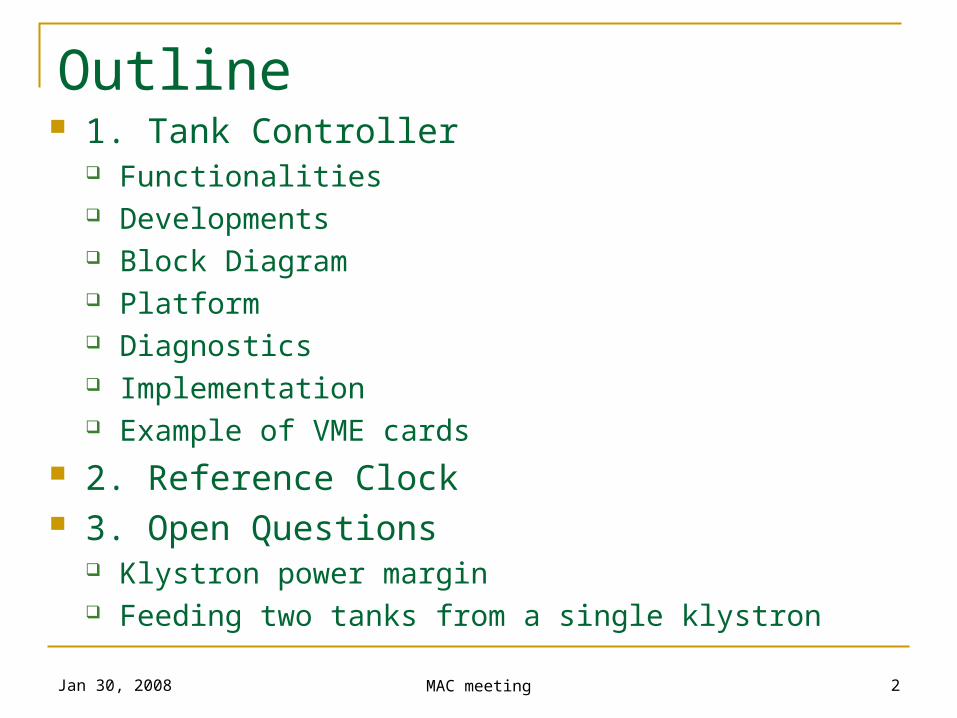
Outline 1. Tank Controller
Functionalities Developments Block Diagram Platform Diagnostics Implementation Example of VME cards
2. Reference Clock 3. Open Questions
Klystron power margin Feeding two tanks from a single klystron

Jan 30, 2008 MAC meeting 3
1. Tank Controller
Jan 30, 2008 MAC meeting 4
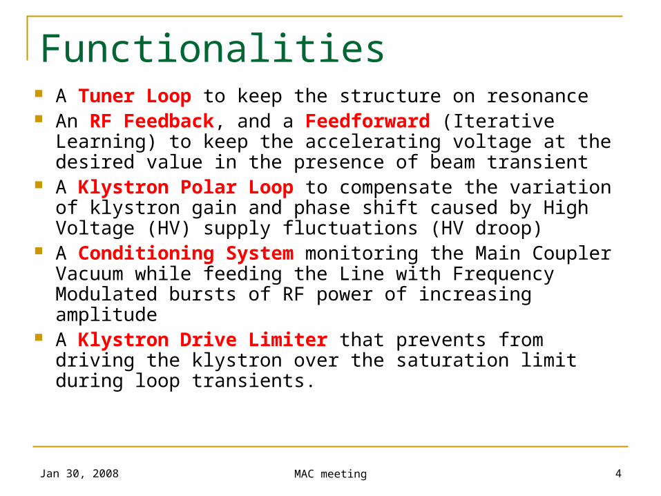
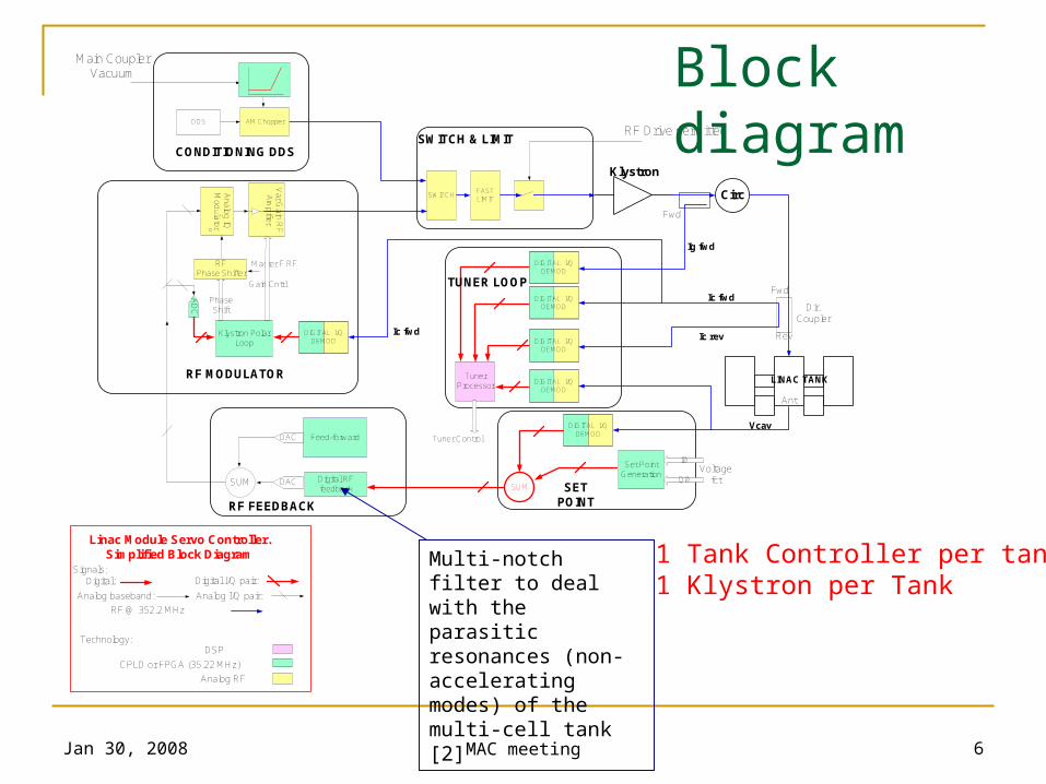
Functionalities A Tuner Loop to keep the structure on resonance An RF Feedback, and a Feedforward (Iterative
Learning) to keep the accelerating voltage at the desired value in the presence of beam transient
A Klystron Polar Loop to compensate the variation of klystron gain and phase shift caused by High Voltage (HV) supply fluctuations (HV droop)
A Conditioning System monitoring the Main Coupler Vacuum while feeding the Line with Frequency Modulated bursts of RF power of increasing amplitude
A Klystron Drive Limiter that prevents from driving the klystron over the saturation limit during loop transients.
Jan 30, 2008 MAC meeting 5
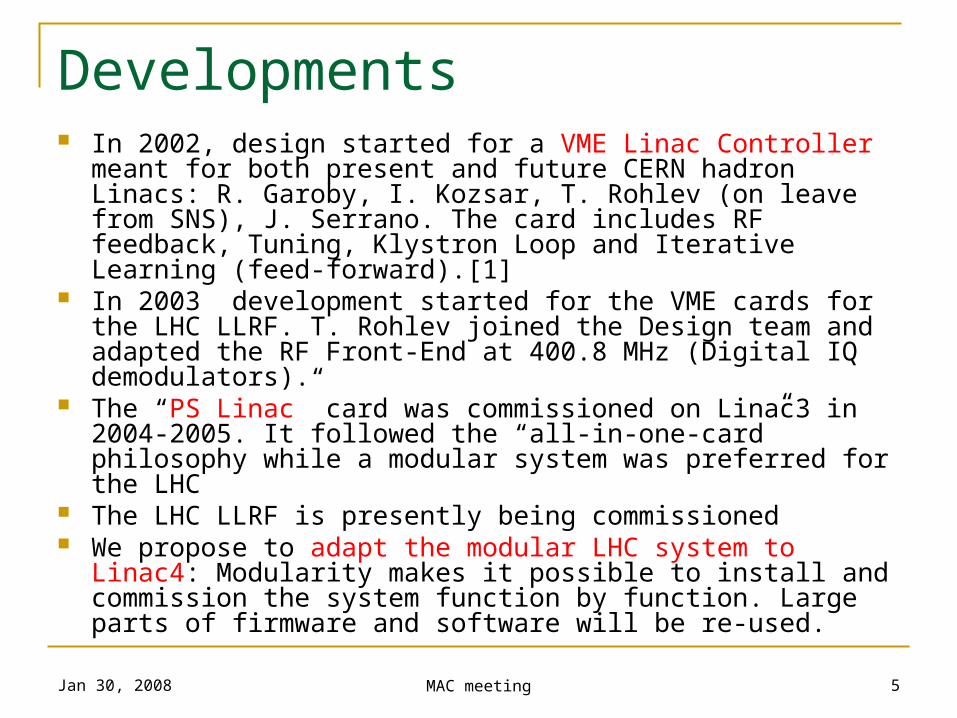
Developments In 2002, design started for a VME Linac Controller meant for
both present and future CERN hadron Linacs: R. Garoby, I. Kozsar, T. Rohlev (on leave from SNS), J. Serrano. The card includes RF feedback, Tuning, Klystron Loop and Iterative Learning (feed-forward).[1]
In 2003 development started for the VME cards for the LHC LLRF. T. Rohlev joined the Design team and adapted the RF Front-End at 400.8 MHz (Digital IQ demodulators).
The “PS Linac” card was commissioned on Linac3 in 2004-2005. It followed the “all-in-one-card” philosophy while a modular system was preferred for the LHC
The LHC LLRF is presently being commissioned We propose to adapt the modular LHC system to Linac4:
Modularity makes it possible to install and commission the system function by function. Large parts of firmware and software will be re-used.
Jan 30, 2008 MAC meeting 6
Linac Module Servo Controller. Simplified Block Diagram
Technology: DSP
CPLD or FPGA (35.22 MHz)
Analog RF
Signals:Digital:
Analog baseband:
Digital I/Q pair:
Analog I/Q pair:
Tuner Processor
Dir. Coupler
Fwd
Rev
Voltage fct
I0
Q0
Set Point Generation
Vcav
SUM
Ic fwd
Ic rev
TUNER LOOP
SET POINT
RF MODULATOR
Klystron
Circ
Ig fwd
Klystron Polar Loop
AD
C
Tuner Control
Ic fwd
CONDITIONING DDSSWITCH & LIMIT
SWITCH
Analo
g IQ
Modu
lator
RF Phase Shifter
Phase Shift
Master F RF
Var G
ain R
F
Am
pifier
DDS AM Chopper
Main Coupler Vacuum
FAST LIMIT
RF Drive permitted
Gain Cntrl
DIGITAL I/Q DEMOD
DIGITAL I/Q DEMOD
DIGITAL I/Q DEMOD
DIGITAL I/Q DEMOD
DIGITAL I/Q DEMOD
DIGITAL I/Q DEMOD
Fwd
Ant
RF @ 352.2 MHz
LINAC TANK
SUM DAC Digital RF feedback
RF FEEDBACK
Feed-forwardDAC
1 Tank Controller per tank1 Klystron per Tank
Block diagram
Multi-notch filter to deal with the parasitic resonances (non-accelerating modes) of the multi-cell tank [2]
Jan 30, 2008 MAC meeting 7
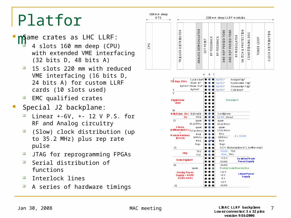
Platform Same crates as LHC LLRF:
4 slots 160 mm deep (CPU) with extended VME interfacing (32 bits D, 48 bits A)
15 slots 220 mm with reduced VME interfacing (16 bits D, 24 bits A) for custom LLRF cards (10 slots used)
EMC qualified crates Special J2 backplane:
Linear +-6V, +- 12 V P.S. for RF and Analog circuitry
(Slow) clock distribution (up to 35.2 MHz) plus rep rate pulse
JTAG for reprogramming FPGAs Serial distribution of functions Interlock lines A series of hardware timings
AGND
-12 V
-6 V
+6 V
+12 V
spare
Analog Power Supply + AGND
(3 pins each)
+3.3 V Extra Digital V
Timings (12x)
Digital data(3x6)
LINAC LLRF backplaneLower connector: 3 x 32 pins
version 9/16/2006
Intlk/Alarm (3x)
A B C
1
32
DGND
Linear Power Supply
Switched Mode Power Supply
Cold reset*
Observation Trig*
Post-mortem Trig*
AnalyzeTrig*
AGND
spare
Clocks (Differential ECL)
+Module Address
(MA3-0)
35.22 MHz-
17.61 MHz-
10 MHz-
Rep-
spare
spare
MA0
MA2
Rep+
10 MHz+
17.61 MHz+
35.22 MHz+
8 x DGND
-5.2 V (for backplane ECL buffers only!)
spare
MA1
MA3
TDI
TCK
DGND, TDO
!ENA, TMS Jtag
FG SDin DGND, SDout
4
5
10
13
21
26
ConfigDone
Cycle Start*
Beam In*
See page 2
BpTA3* / Beam Out*
BpTA4*
BpTB1*
BpTB2*
BpTB3*
BpTB4*
Inj Enable
Module Serial Number Bus
CLO
CK
DIS
TR
IBU
TIO
N
TU
NE
R L
OO
P
CO
ND
ITIO
NIN
G D
DS
SW
ITC
H &
PR
OT
EC
TIO
N
RF
MO
DU
LA
TO
R
ON
E R
EP
PE
RIO
D F
DB
K
ON
E R
EP
PE
RIO
D F
DB
K
RF
FE
ED
BA
CK
RF
FE
ED
BA
CK
SE
T P
OIN
T
AN
ALO
G D
EM
OD
ULA
TO
R
TR
IGG
ER
DIS
TR
IBU
TO
R
220 mm deep LLRF modules 160 mm deep
OTS
CP
U
Jan 30, 2008 MAC meeting 8
Diagnostics Important signals (~30/controller) are stored for monitoring Two sets of memory
Post-Mortem memory: Free-running, stopped by specific machine-wide post-mortem trigger, fixed sampling rate. Meant to correlate acquisitions after a fault.
Observation: Piloted by operator that sets sample rate and triggers the acquisition. Meant for monitoring during operation.
Built-in Network Analyzer Excitation memories to inject signals (step, sine-wave, white noise,…)
coupled with observation memories implement a Signal Analyzer Fully remote controlled
Jan 30, 2008 MAC meeting 9
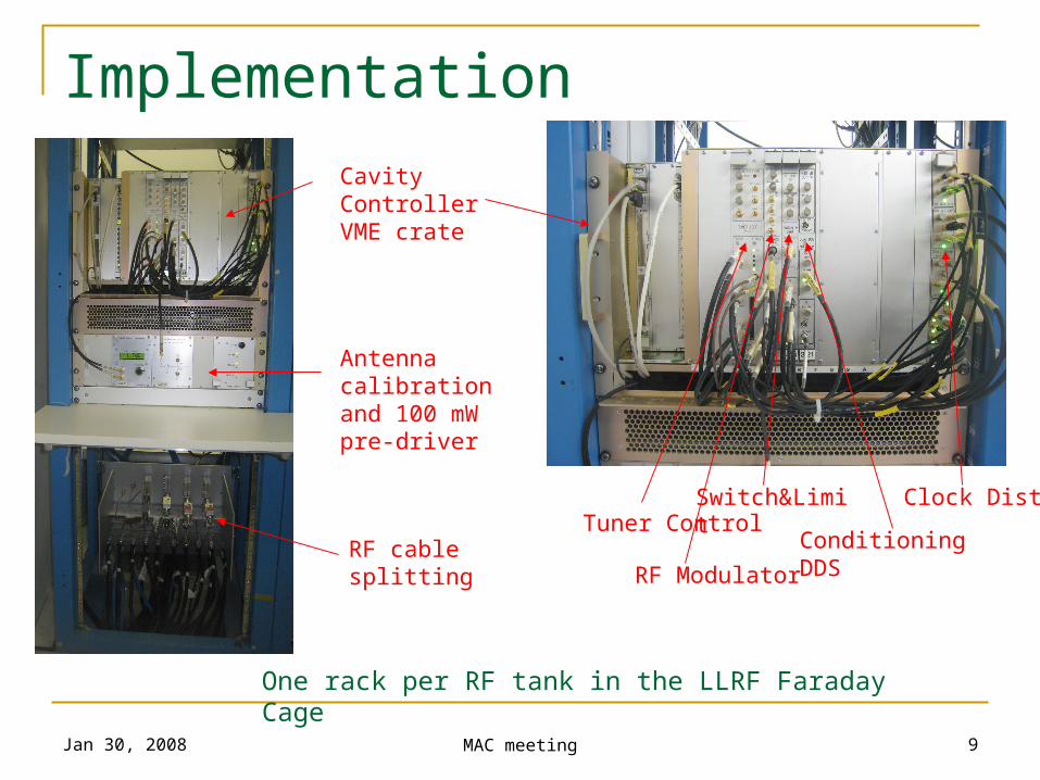
ImplementationCavity Controller VME crate
Antenna calibration and 100 mW pre-driver
RF cable splitting
One rack per RF tank in the LLRF Faraday Cage
Tuner Control
RF Modulator
Switch&Limit
Conditioning DDS
Clock Distri
Jan 30, 2008 MAC meeting 10
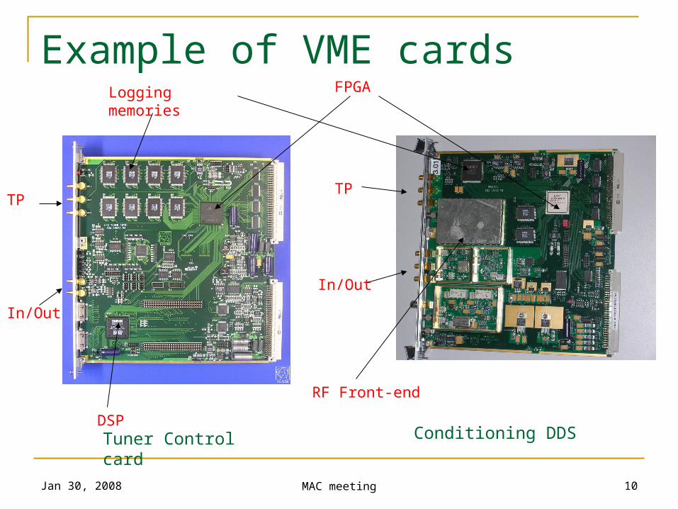
Example of VME cardsLogging memories FPGA
DSP
RF Front-end
Tuner Control card Conditioning DDS
In/Out
In/Out
TPTP
Jan 30, 2008 MAC meeting 11
2. Reference clocks
Jan 30, 2008 MAC meeting 12
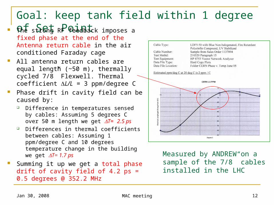
Goal: keep tank field within 1 degree of Set Point The strong RF feedback imposes a fixed phase at the end of the Antenna return cable in the air conditioned Faraday cage
All antenna return cables are equal length (~50 m), thermally cycled 7/8” Flexwell. Thermal coefficient L/L = 3 ppm/degree C
Phase drift in cavity field can be caused by: Difference in temperatures sensed by
cables: Assuming 5 degrees C over 50 m length we get T= 2.5 ps
Differences in thermal coefficients between cables: Assuming 1 ppm/degree C and 10 degrees temperature change in the building we get T= 1.7 ps
Summing it up we get a total phase drift of cavity field of 4.2 ps = 0.5 degrees @ 352.2 MHz
Measured by ANDREW on a sample of the 7/8” cables installed in the LHC
Jan 30, 2008 MAC meeting 13
3. Open questions
Jan 30, 2008 MAC meeting 14
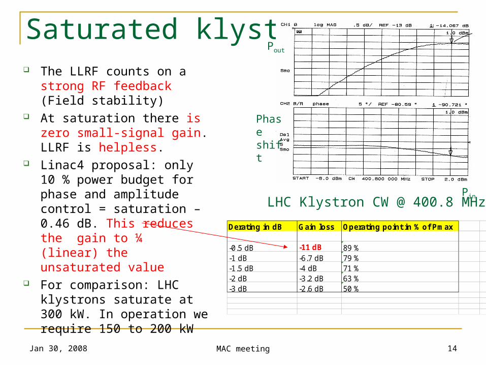
Saturated klystron The LLRF counts on a strong
RF feedback (Field stability) At saturation there is zero
small-signal gain. LLRF is helpless.
Linac4 proposal: only 10 % power budget for phase and amplitude control = saturation – 0.46 dB. This reduces the gain to ¼ (linear) the unsaturated value
For comparison: LHC klystrons saturate at 300 kW. In operation we require 150 to 200 kW
LHC Klystron CW @ 400.8 MHz
Pout
Pin
Phase shift
Derating in dB Gain loss Operating point in % of Pmax
-0.5 dB -11 dB 89 %-1 dB -6.7 dB 79 %-1.5 dB -4 dB 71 %-2 dB -3.2 dB 63 %-3 dB -2.6 dB 50 %
Jan 30, 2008 MAC meeting 15
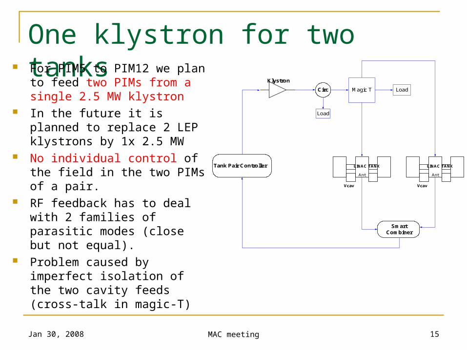
One klystron for two tanks For PIM5 to PIM12 we plan to
feed two PIMs from a single 2.5 MW klystron
In the future it is planned to replace 2 LEP klystrons by 1x 2.5 MW
No individual control of the field in the two PIMs of a pair.
RF feedback has to deal with 2 families of parasitic modes (close but not equal).
Problem caused by imperfect isolation of the two cavity feeds (cross-talk in magic-T)
Klystron
Circ
Tank Pair Controller
Magic T Load
Vcav
Ant
LINAC TANK
Vcav
Ant
LINAC TANK
Load
Smart Combiner
Jan 30, 2008 MAC meeting 16
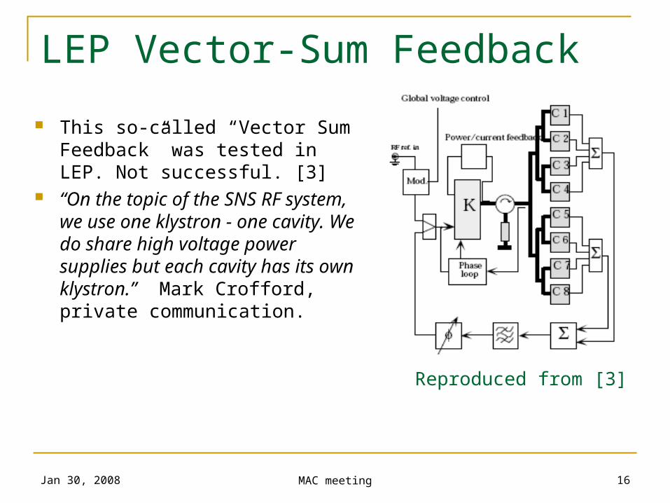
LEP Vector-Sum Feedback
This so-called “Vector Sum Feedback” was tested in LEP. Not successful. [3]
“On the topic of the SNS RF system, we use one klystron - one cavity. We do share high voltage power supplies but each cavity has its own klystron.” Mark Crofford, private communication.
Reproduced from [3]
Jan 30, 2008 MAC meeting 17
References
[1] J. Broere, I. Kozsar, R. Garoby, A. Rohlev, J. Serrano, All Digital IQ Servo-System for CERN Linacs, EPAC 2004
[2] D. Boussard , H.P. Kindermann, V. Rossi, RF Feedback applied to a multicell superconducting cavity, EPAC 88
[3] E. Peschard, RF System for High Intensity, Chamonix 1996
Jan 30, 2008 MAC meeting 18
Thank you…
Jan 30, 2008 MAC meeting 19
Additional material if questions arise
Jan 30, 2008 MAC meeting 20
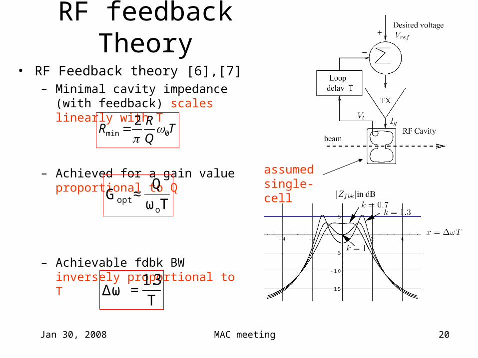
RF feedback Theory
• RF Feedback theory [6],[7]– Minimal cavity impedance (with
feedback) scales linearly with T
– Achieved for a gain value proportional to Q
– Achievable fdbk BW inversely proportional to T
TQ
RR 0min
2
T
3.1=ωΔ
assumed single-cell
Tω
Q≈G
oopt