Life Cycle Assessment - Okala Practitionerokala.net/presentations/14 chapter10 Life Cycle...
29
Life Cycle Assessment Okala Practitioner Chapter 10
Transcript of Life Cycle Assessment - Okala Practitionerokala.net/presentations/14 chapter10 Life Cycle...

Life Cycle Assessment
Okala Practitioner Chapter 10
Life Cycle Assessment
Life cycle assessment (LCA) is objec:ve (based on quan:fied measurements) and comprehensive (including the en:re lifecycle of the system and including most impacts categories).
Interna:onal standards (ISO 14040 series) guide the proper prac:ce of LCA. Interna:onal ins:tu:ons and companies use LCA.

Single-figure LCA
Okala Impact Factors are single-‐figure LCA that designers can use to quickly model the overall impacts of products.
Single-‐figure LCA is a form of LCA that combines all the necessary LCA steps in one mul:plica:on impact factor. Single-‐figure LCA reports one numerical score per material or process. The science of LCA is described in more detail in chapter 14.

Ways to use Okala Impact Factors Okala Impact Factors can be used in different ways to understand the environmental performance of a design concept.
Any of these approaches may be instruc:ve if you need to compare two or more design alterna:ves:
1. Simple Screening
2. Subassembly comparison
3. Complete System LCA

1. Simple Screening
Simple screening compares one material or process to another material or process for a specific applica:on.
In this example, we compare materials that could be used in a wallet. We es:mate the weight of each material, find the Okala Impact Factor value (pages 44-‐48), and mul:ply these to es:mate the resul:ng impact.

1. Simple Screening
Alterna:ve materials (or processes) have different mechanical, durability, economic and aesthe:c characteris:cs. The designer decides which lower impac:ng alterna:ve best meets the needs of the applica:on.
2. Subassembly comparison
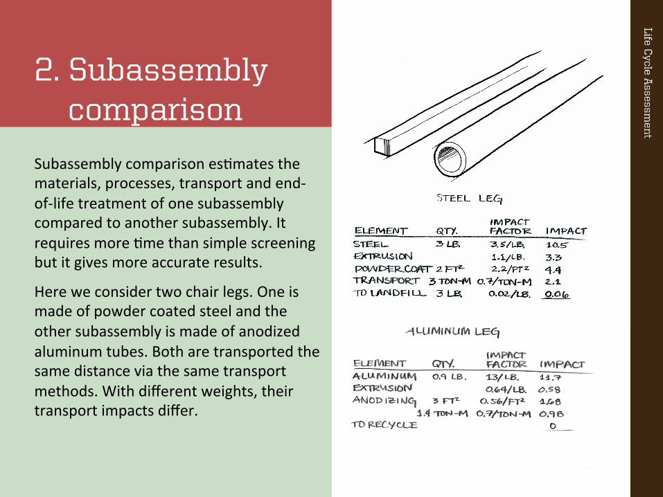
Subassembly comparison es:mates the materials, processes, transport and end-‐of-‐life treatment of one subassembly compared to another subassembly. It requires more :me than simple screening but it gives more accurate results.
Here we consider two chair legs. One is made of powder coated steel and the other subassembly is made of anodized aluminum tubes. Both are transported the same distance via the same transport methods. With different weights, their transport impacts differ.
2. Subassembly comparison
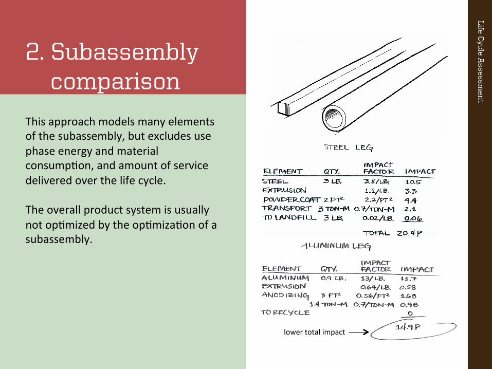
This approach models many elements of the subassembly, but excludes use phase energy and material consump:on, and amount of service delivered over the life cycle. The overall product system is usually not op:mized by the op:miza:on of a subassembly.
lower total impact
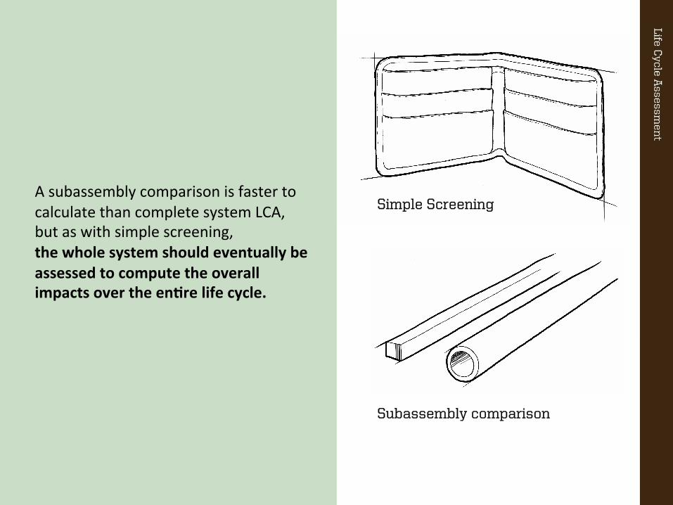
A subassembly comparison is faster to calculate than complete system LCA, but as with simple screening, the whole system should eventually be assessed to compute the overall impacts over the enBre life cycle.
Subassembly comparison
Simple Screening
3. Complete System LCA
Complete system LCA is the most reliable assessment method for capturing impacts over the en:re life cycle.
It should be used when a comprehensive understanding of the system’s impacts is needed.
Complete system LCA requires you to clearly define system characteris:cs listed on the right.
a. System boundary b. Product lifetime c. Functional unit d. System bill of materials

a. System boundary
A system boundary specifies what is and is not included in the assessment. We include as much of the product system as possible, but we can lack data for items with complex composi:ons (detergent, toothpaste, etc.). These are typically leT out of this level of assessment.
Other items, such as the energy required to wash a drinking glass in a washing machine, can usually be accurately es:mated.
Complete System LCA
Complete System LCA
a. System boundary
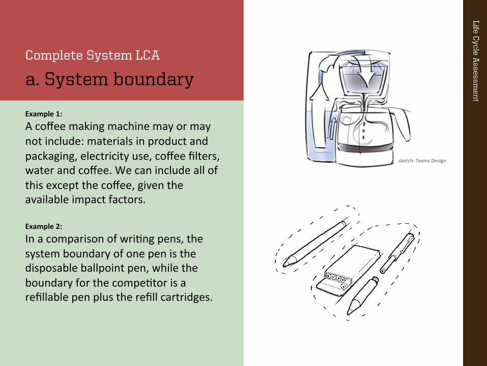
Example 1:
A coffee making machine may or may not include: materials in product and packaging, electricity use, coffee filters, water and coffee. We can include all of this except the coffee, given the available impact factors. Example 2:
In a comparison of wri:ng pens, the system boundary of one pen is the disposable ballpoint pen, while the boundary for the compe:tor is a refillable pen plus the refill cartridges.
sketch: Teams Design
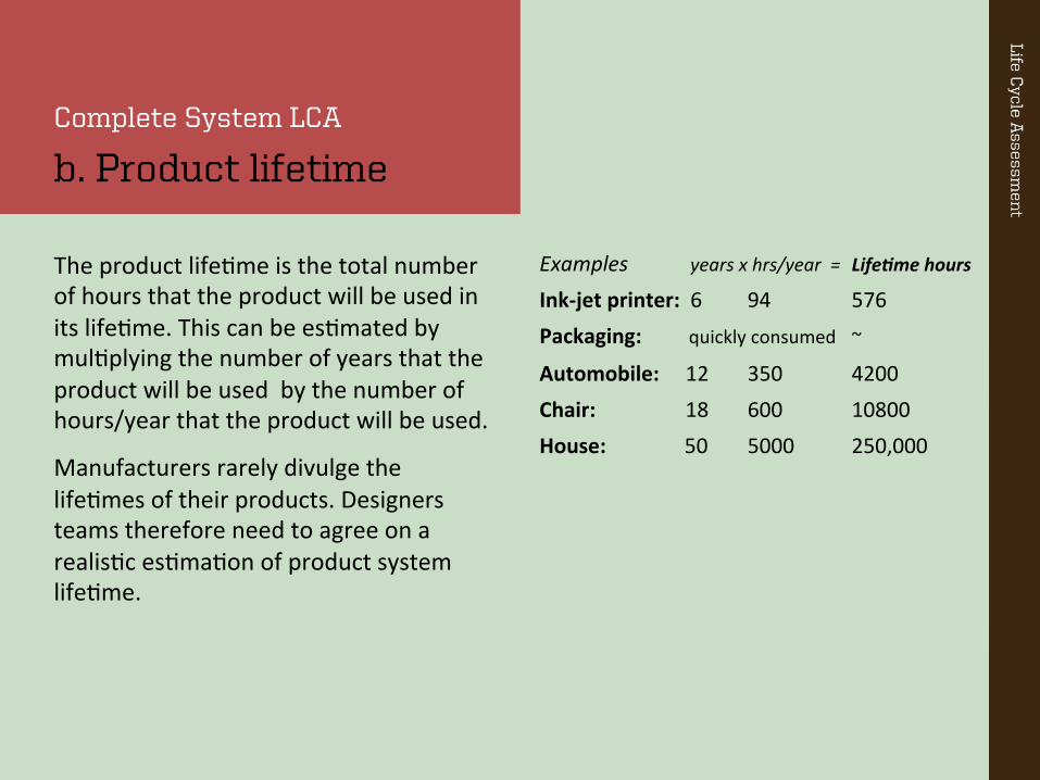
The product life:me is the total number of hours that the product will be used in its life:me. This can be es:mated by mul:plying the number of years that the product will be used by the number of hours/year that the product will be used.
Manufacturers rarely divulge the life:mes of their products. Designers teams therefore need to agree on a realis:c es:ma:on of product system life:me.
Complete System LCA
b. Product lifetime
Examples years x hrs/year = Life%me hours
Ink-‐jet printer: 6 94 576 Packaging: quickly consumed ~
Automobile: 12 350 4200 Chair: 18 600 10800 House: 50 5000 250,000
Product Wear-out l ife, years Technology cycle, yearsaudio system 9 4automobile 20 7bubblejet printer 8 5cellular phone 3 1computer 6 2computer mouse 6 4cordless phone 10 5CRT display 6 3digital copier 5 2fax machine 6 2hand held vacuum 4 6inkjet printer 4 2laserjet printer 8 5LCD display 5 2miniature robot 5 5photocopier 5 5portable CD player 5 10portable radio 10 2single use camera 2 4telephone 5 2television 11 4typerwiter 15 9vacuum cleaner 8 7video projector 5 2washing machine 10 5
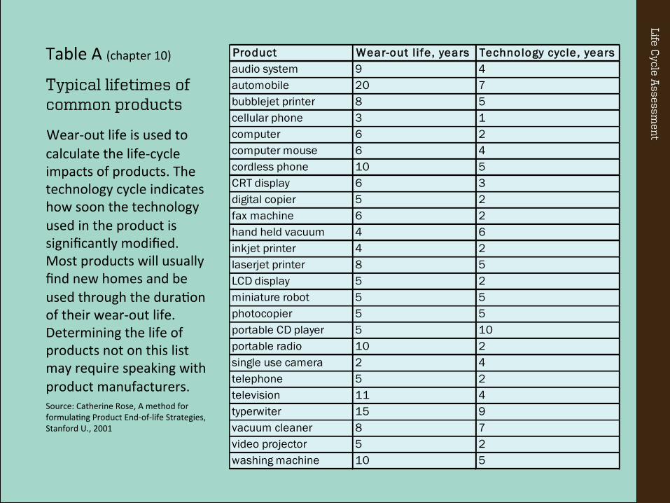
Table A (chapter 10)
Typical lifetimes of common products
Wear-‐out life is used to calculate the life-‐cycle impacts of products. The technology cycle indicates how soon the technology used in the product is significantly modified. Most products will usually find new homes and be used through the dura:on of their wear-‐out life. Determining the life of products not on this list may require speaking with product manufacturers. Source: Catherine Rose, A method for formula:ng Product End-‐of-‐life Strategies, Stanford U., 2001
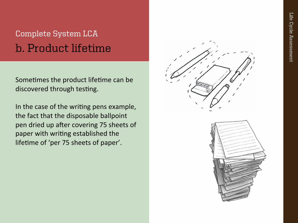
Complete System LCA
b. Product lifetime
Some:mes the product life:me can be discovered through tes:ng. In the case of the wri:ng pens example, the fact that the disposable ballpoint pen dried up aTer covering 75 sheets of paper with wri:ng established the life:me of ‘per 75 sheets of paper’.
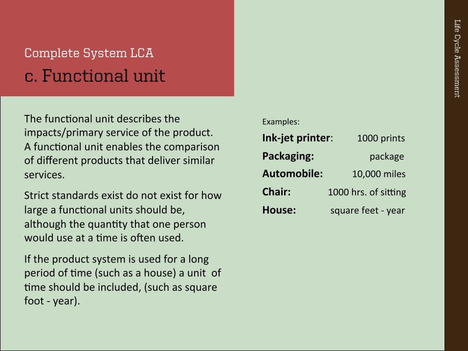
The func:onal unit describes the impacts/primary service of the product. A func:onal unit enables the comparison of different products that deliver similar services.
Strict standards exist do not exist for how large a func:onal units should be, although the quan:ty that one person would use at a :me is oTen used.
If the product system is used for a long period of :me (such as a house) a unit of :me should be included, (such as square foot -‐ year).
Complete System LCA
c. Functional unit
Examples:
Ink-‐jet printer: 1000 prints Packaging: package Automobile: 10,000 miles
Chair: 1000 hrs. of sieng
House: square feet -‐ year
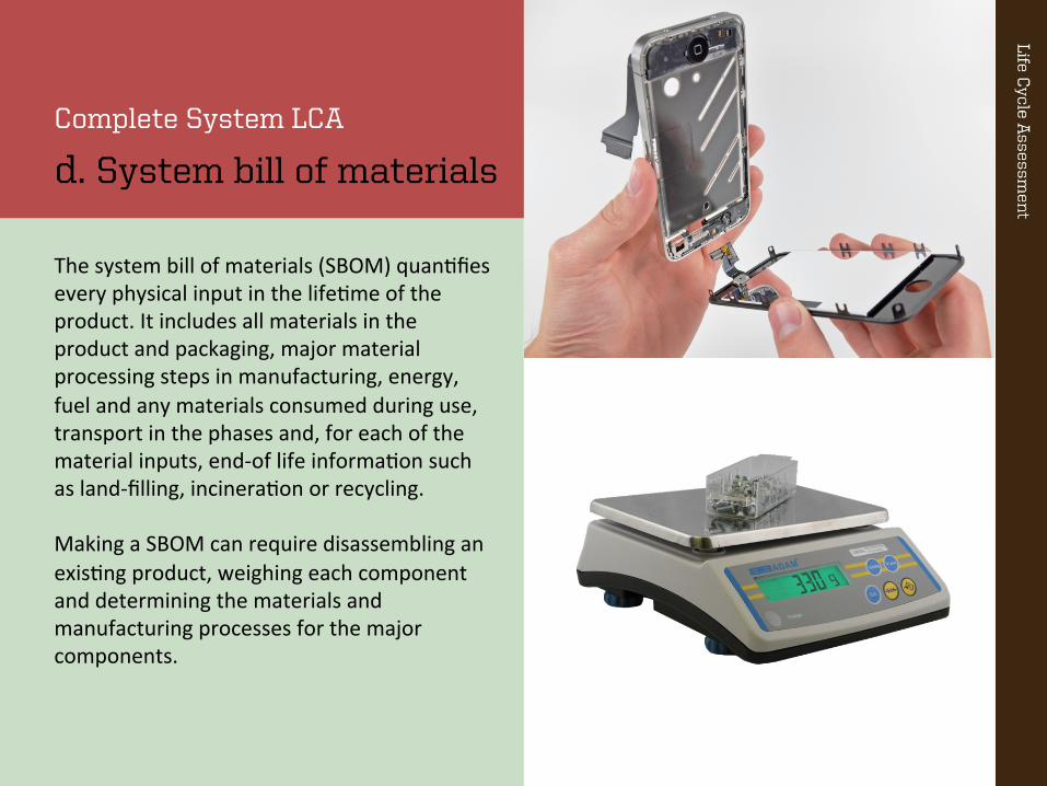
The system bill of materials (SBOM) quan:fies every physical input in the life:me of the product. It includes all materials in the product and packaging, major material processing steps in manufacturing, energy, fuel and any materials consumed during use, transport in the phases and, for each of the material inputs, end-‐of life informa:on such as land-‐filling, incinera:on or recycling. Making a SBOM can require disassembling an exis:ng product, weighing each component and determining the materials and manufacturing processes for the major components.
Complete System LCA
d. System bill of materials

We apply these steps to a chair designed by Charles Eames and manufactured by Herman Miller.
This example shows the calcula:on steps in the complete system LCA process.
Complete System LCA
Example: Molded Plastic Chair

Step 1. Define a. system boundary b. product lifetime c. functional unit
The system boundary, life:me, and func:onal unit are defined. The chair is used 600 hours/year for 12 years, which delivers a life:me of 7,200 hours.
System boundary: excludes: cleaning during use
LifeBme: 600 hour/yr x 12 year = 7,200 hour
FuncBonal unit: impacts/ hour used
This example is also found on page 38 of Okala PracBBoner.
Step 2: Make system bill of materials
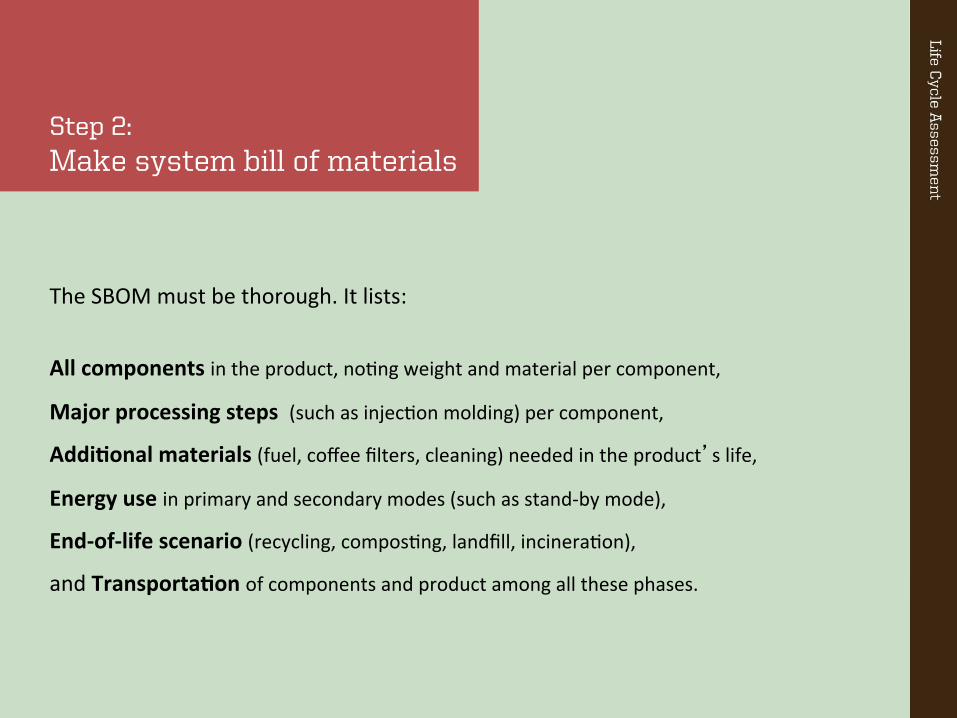
The SBOM must be thorough. It lists:
All components in the product, no:ng weight and material per component,
Major processing steps (such as injec:on molding) per component,
AddiBonal materials (fuel, coffee filters, cleaning) needed in the product’s life,
Energy use in primary and secondary modes (such as stand-‐by mode),
End-‐of-‐life scenario (recycling, compos:ng, landfill, incinera:on),
and TransportaBon of components and product among all these phases.
Step 2: SBOM for the chair
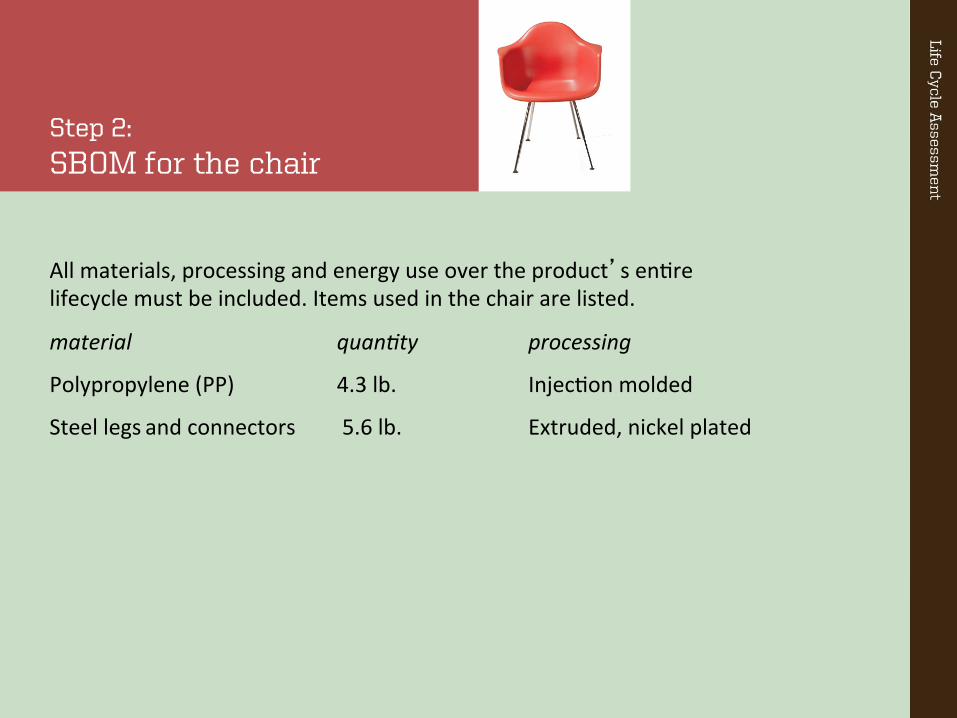
All materials, processing and energy use over the product’s en:re lifecycle must be included. Items used in the chair are listed.
material quan4ty processing
Polypropylene (PP) 4.3 lb. Injec:on molded
Steel legs and connectors 5.6 lb. Extruded, nickel plated
Step 2: Transportation
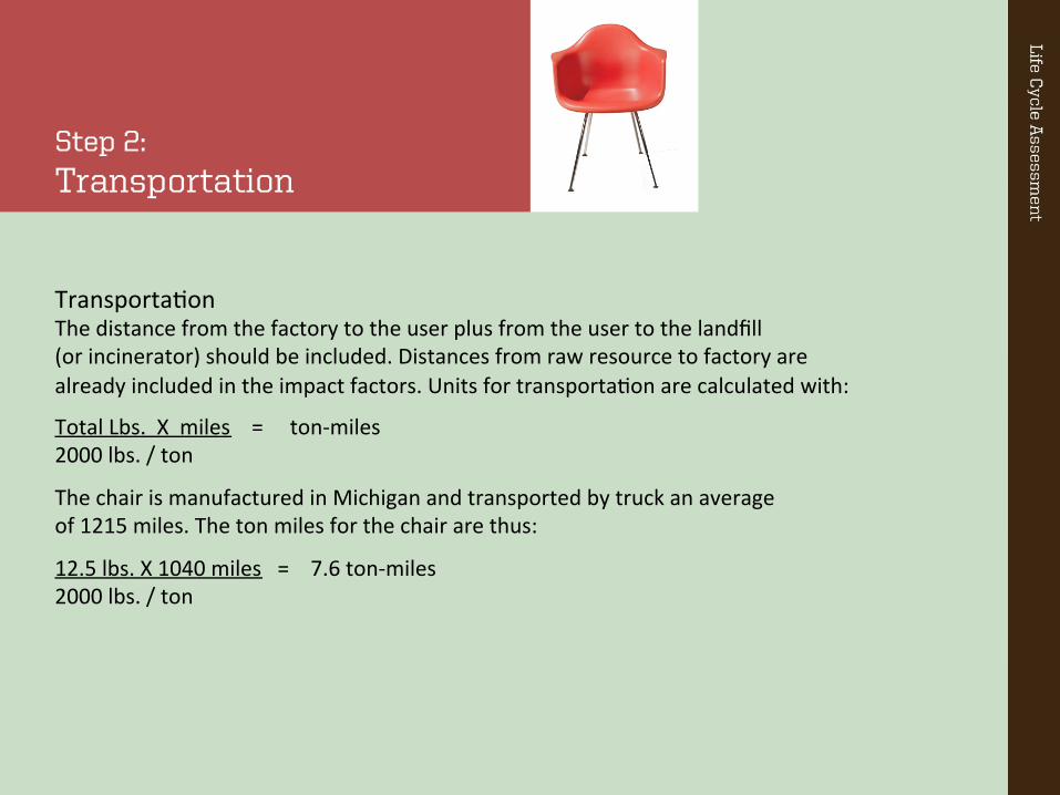
Transporta:on The distance from the factory to the user plus from the user to the landfill (or incinerator) should be included. Distances from raw resource to factory are already included in the impact factors. Units for transporta:on are calculated with:
Total Lbs. X miles = ton-‐miles 2000 lbs. / ton
The chair is manufactured in Michigan and transported by truck an average of 1215 miles. The ton miles for the chair are thus:
12.5 lbs. X 1040 miles = 7.6 ton-‐miles 2000 lbs. / ton

Step 3: Calculate impacts/ lifetime
SBOM amount Okala factor/unit impact points
Recycled polyethylene 4.3 lb. 1.9/lb. 8.17
Process: Injec:on mold 4.3 0.72/lb. 3.1
Steel 3.6 lb. 25/lb. 12.6
Process: extrude 3.6 lb. 11/lb. 3.96
Process: Nickel plate 112 sq. inches 0.57/sq. inch 0.44
Transport 28 ton truck 7.6 ton-‐mi. 0.32/ton-‐mi. 2.43
Landfill PP 4.3 lb. 0.26/lb. 1.12
Landfill steel 3.6 lb. 0.02/lb. 0.08
total life:me impacts 31.9 Okala points
Step 3: Calculate impacts/ lifetime
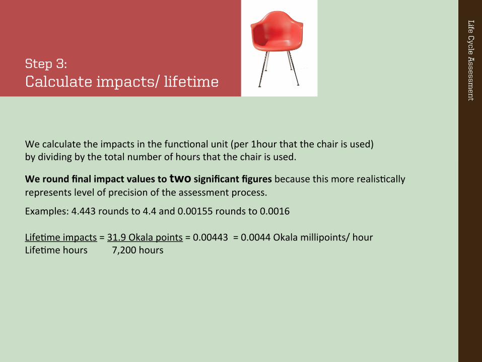
We calculate the impacts in the func:onal unit (per 1hour that the chair is used) by dividing by the total number of hours that the chair is used.
We round final impact values to two significant figures because this more realis:cally represents level of precision of the assessment process.
Examples: 4.443 rounds to 4.4 and 0.00155 rounds to 0.0016 Life:me impacts = 31.9 Okala points = 0.00443 = 0.0044 Okala millipoints/ hour Life:me hours 7,200 hours

Discussion
Does anything surprise you about the results of the impact assessment of the chairs?
Should you review any of the steps again?
Did we leave anything out of the bill-‐of-‐materials that should have been included?
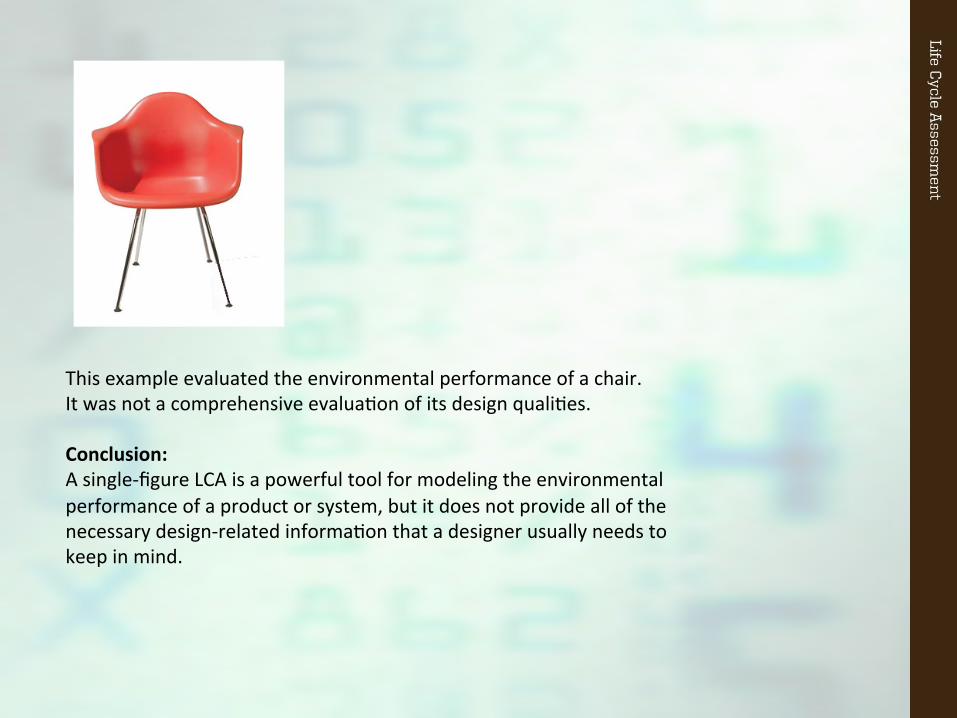
This example evaluated the environmental performance of a chair. It was not a comprehensive evalua:on of its design quali:es. Conclusion: A single-‐figure LCA is a powerful tool for modeling the environmental performance of a product or system, but it does not provide all of the necessary design-‐related informa:on that a designer usually needs to keep in mind.

Building LCA
Using Okala Impact Factors to make LCAs of buildings is explained on page 40. This requires addi:onal soTware to model building energy needs for a par:cular loca:on. Further the system boundary usually excludes some of the building infrastructure (such as electrical and plumbing systems).
Although Building LCAs model simplified models of a structure, they can provide insighjul informa:on about the environmental performance of these large systems.
Carbon Footprinting
You can follow a similar calcula:on process as is used with the Okala Impact Factors to make carbon footprints of product systems. To do this, you use the CO2 equivalent that is listed at the right edge of each Okala Impact Factor.
Although carbon footprin:ng is oTen used, it measures only one impact category (climate change), and does not reflect the mul:ple impact categories in the Okala Impact Factors.
Depending on the system being assessed and the audience, carbon footprints may be useful.

Okala Practitioner Integrating Ecological Design
The Okala Team ini:ated the collabora:on with the US EPA and the Industrial Designers Society of America (IDSA) in 2003. The team developed Okala Prac44oner with support from Autodesk, IBM, Eastman Chemical and the IDSA Ecodesign Sec:on.
Okala Prac44oner is available through amazon.com.
More informa:on and the free Okala Ecodesign Strategy App can be found at Okala.net. Copyright © 2014, Okala presenta:ons are free for educa:onal uses, but fully protected from unlicensed commercial reproduc:on or use. Okala™ is a registered trademark of the Okala Team
The Okala Team: Philip White IDSA Associate Professor, Arizona State University Louise St. Pierre Associate Professor, Emily Carr University of Art + Design
Steve Belle:re IDSA Professor, Southern Illinois University Carbondale
This presenta:on is part of an educa:onal presenta:on series that supports teaching from the Okala Prac44oner guide.
Okala Prac44oner and these presenta:ons were created by the Okala Team to disseminate fact-‐based knowledge about ecological design to the design disciplines and business.
Unless provided in the presenta:ons, Informa:on sources are found in the Okala Prac44oner guide.