LEVEL METER FOR ANALOGUE AND DIGITAL TV … INSTRUCTION MANUAL LEVEL METER FOR ANALOGUE AND DIGITAL...
35
MC-377 INSTRUCTION MANUAL LEVEL METER FOR ANALOGUE AND DIGITAL TV MC-377 1 GENERAL 1.1 Description The MC-377 is a compact, light-weight, portable instrument which offers installers all the basic functions needed to guarantee the good operation of analogue and digital TV installations. The instrument covers television bands, hyperband, cable television S channels as well as the satellite intermediate frequency band in K/C, up to 2050 MHz. The MC-377 has two main operation modes: Monitor mode and Spectrum Analyser mode: The Spectrum Analyser mode enables all the signals present in a band to be viewed on the monitor. The bandwidth represented in the spectrum mode can be selected as either the complete band or a bandwidth defined by the user (from approximately 1/3 of the band in use to almost zero). In the Monitor mode the instrument demodulates the analogue TV signal, which enables a terrestrial or satellite television channel to be identified and its reception observed. The signal level in monitor mode is represented by an analogue bar at the top of the image whose length varies in proportion to the power received. In addition it enables the line synchronism pulse to be observed, overlaid on the top centre of the screen. The MC-377 enables you to easily take the following measurements: analogue signal levels, digital channel power and Carrier to Noise ratio (C/N) in analogue and digital channels. The instrument can also supply the voltage needed to power external units: aerial pre-amplifiers and LNBs with 13 or 18 V, together with a 22 kHz signal superimposed onto the voltage for the commutation of polarisation, band or signal switches. September 1999 Page 1
Transcript of LEVEL METER FOR ANALOGUE AND DIGITAL TV … INSTRUCTION MANUAL LEVEL METER FOR ANALOGUE AND DIGITAL...

MC-377 INSTRUCTION MANUAL
LEVEL METER FOR ANALOGUE ANDDIGITAL TV
MC-377
1 GENERAL
1.1 Description
The MC-377 is a compact, light-weight, portable instrument which offers installersall the basic functions needed to guarantee the good operation of analogue and digitalTV installations.
The instrument covers television bands, hyperband, cable television S channels aswell as the satellite intermediate frequency band in K/C, up to 2050 MHz.
The MC-377 has two main operation modes: Monitor mode and Spectrum Analysermode:
The Spectrum Analyser mode enables all the signals present in a band to be viewedon the monitor. The bandwidth represented in the spectrum mode can be selected aseither the complete band or a bandwidth defined by the user (from approximately 1/3of the band in use to almost zero).
In the Monitor mode the instrument demodulates the analogue TV signal, whichenables a terrestrial or satellite television channel to be identified and its receptionobserved. The signal level in monitor mode is represented by an analogue bar at thetop of the image whose length varies in proportion to the power received. In addition itenables the line synchronism pulse to be observed, overlaid on the top centre of thescreen.
The MC-377 enables you to easily take the following measurements: analoguesignal levels, digital channel power and Carrier to Noise ratio (C/N) in analogue anddigital channels.
The instrument can also supply the voltage needed to power external units: aerialpre-amplifiers and LNBs with 13 or 18 V, together with a 22 kHz signal superimposedonto the voltage for the commutation of polarisation, band or signal switches.
September 1999 Page 1
MC-377 INSTRUCTION MANUAL
1.2 Specifications
TUNINGVHF LOW VHF band (VLO) from 48.25 to 168.25 MHz
HIGH VHF band (VHI) from 175,25 to 447.25 MHzUHF UHF band, from 455.25 to 855.25 MHzSAT Satellite IF band from 950 to 2050 MHz
Resolution 10 kHz in VHF and UHF100 kHz in SAT
Frequency indication By digital frequency counterDisplay LCD, 5 digits
RF INPUTS TV and SATImpedance 75 ΩConnector BNCMaximum signal 130 dBµVMaximum input voltage
DC to 100 Hz 50 V rms (powered by the mains supply)30 V rms (not powered by the mains supply)
5 MHz to 2050 MHz 130 dBµV
MEASUREMENTSTypes of measurements Analogue signals level
Digital channels powerC/N ratio of analogue and digital signals
Terrestrial digital signals measurement Calibrated for a channel bandwidth of 7.607 MHzSatellite digital signalsmeasurement Calibrated for a Symbol Rate of 27.500 MBaudsSensibility
TV bands From 20 dBµV to 130 dBµV analogue signalsFrom 35 dBµV to 125 dBµV digital signals
Satellite band From 40 dBµV to 100 dBµV analogue signalsFrom 45 dBµV to 95 dBµV digital signals
Reading Scale calibrated in dBµV (linear) for analoguesignals level measurement.Scale calibrated in dBµV (linear) for digitalchannels power measurement.Scale calibrated in dB (linear) for C/N ratiomeasurement of analogue and digital signals.
Page 2 September 1999

MC-377 INSTRUCTION MANUAL
Scales range 60 dB for TV analogue signals45 dB for TV digital signals40 dB for SAT analogue signals30 dB for TV digital signals60 dB for C/N measurement
IF bandwidth 250 kHz (TV) and 18 MHz (SAT)RF attenuators TV bands: 50 dB in 10 and 20 dB steps
Satellite band: 20 dBTotal accuracy (25 ºC ± 5 ºC)
TV bands ± 4 dB Satellite band ± 6 dB
When carrying out level and power measurements it is necessary to apply the correctionchart which is delivered with the instrument.
Level acoustic indication Tone whose frequency varies with the receivedsignal level.
SPURIOUS SIGNALSLOW VHF (VLO)
Analogue signals < 20 dBµV (input 65 dBµV not attenuated)Digital signals < 35 dBµV (input 75 dBµV not attenuated)
HIGH VHF (VHI)Analogue signals < 20 dBµV (input 75 dBµV not attenuated)Digital signals < 35 dBµV (input 75 dBµV not attenuated)
UHFAnalogue signals < 20 dBµV (input 75 dBµV not attenuated)Digital signals < 35 dBµV (input 75 dBµV not attenuated)
SATAnalogue signals < 40 dBµV (input 75 dBµV not attenuated)Digital signals < 45 dBµV (input 75 dBµV not attenuated)
MONITOR B&W CRT 4,5" Monitor controls Brightness and contrastMonitor mode TV analogue signals demodulation
TV standard Multistandard B, G, H and /L according to CCIRstandars
MC-377/1 Version Multistandard M, N/L according to CCIR standardsMC-377/2 Version Multinorm D, K/L according to CCIR standardsMC-377/4 Version Multinorm I/L according to CCIR standards
Sensibility > 40 dBµV for correct synchronism in TV bands
September 1999 Page 3

MC-377 INSTRUCTION MANUAL
Spectrum Analyser ModeBandwidth
MAX mode Spectrum of the entire selected band, with amarker on the tuned frequency.
SPAN mode Frequency spectrum representation around thetuned frequency, with variable bandwidth from 1/3of the band (approximately) to almost zero.
SOUND Analogue channelsDemodulation
TV MonoTER According to CCIR standard or manual tuning
between 4.5 and 6,5 MHz except in the L standardand version MC-377/1.
SAT Tuning between 5 and 8 MHzLevel indication Tone whose frequency varies according to signal
levelOutput power 0.2 WVolume controlBuilt-in speaker
EXT. UNITS POWER SUPPLY 0/13/18V, 350 mA. Indicator of consumption higherthan 50 mA and protections against short circuitsand 50 VAC.
22 kHz signal Selectable ON/OFF Voltage 0.6 V ± 0.2 VFrequency 22 kHz ± 4 kHz
POWER SUPPLYBattery
Voltage 12 V-2.6 AhAutonomy >1 hour without external units powering (at 30%
on/off).40 minutes approximately with external unitspowering (at 30% on/off).
Recharging time 8 h approximately (starting from a total discharge)Protections Low battery indication (blinking colon on the
display).Minimum charge automatic cut-off.
Mains supplyVoltage 110-125-220-230/240 V AC with voltage selectorFrequency 50-60 HzConsumption 55 W
Page 4 September 1999

MC-377 INSTRUCTION MANUAL
OPERATING ENVIRONMENTAL CONDITIONSAltitude Up to 2000 mTemperature margin From 5 ºC to 40 ºCMax. relative humidity 80% (up to 31 ºC),
decreasing lineally up to 50% at 40 ºC.
MECHANICAL FEATURESDimensions W. 280 x H. 95 x D. 250 mm (without carrying bag)Weight 5.2 kg (battery included)
INCLUDED ACCESSORIESModel DescriptionAD-050 BNC/m-ANT/f adapterAD-051 BNC/m -F/f adapterDC-236 Carrying bagCA-005 Power cordCB-041 Rechargeable battery Pb 12 V / 2.6 Ah
Fuse 3.15 A - T - 250 V IEC 127
OPTIONAL ACCESSORIESModel DescriptionAMC/1 Reference antennaAD-052 BNC/m-TV/f (NF) adapterAT-20 20 dB attenuator CV-550 5-50 MHz converterLN-370B Low noise amplifierMC-75/300 75 Ω (BNC) / 300 Ω (TV) adapterNG-282 Noise generator
OPTIONSOPT-377/10 Level and power measuring scales in dBmVOPT-377/63 Satellite band extension up to 2100 MHz
VERSIONSMC-377/1 Multinorm M, N/L according to CCIR standardsMC-377/2 Multinorm D, K/L according to CCIR standardsMC-377/4 Multinorm I/L according to CCIR standards
September 1999 Page 5

MC-377 INSTRUCTION MANUAL
Page 6 September 1999

MC-377 INSTRUCTION MANUAL
2 SAFETY RULES
2.1 General
* Use this equipment connected only to devices or systems with their negative ofmeasurement connected to ground potential.
* This is a class I equipment, for safety reasons plug it to a supply line with thecorresponding ground terminal.
* This equipment can be used in Overvoltage Category II installations and PollutionDegree 2 environments.
* When using some of the following accessories use only the specified ones toensure safety:
Rechargeable batteryPower cord
* Observe all specified ratings both of supply and measurement.
* Remember that voltages higher than 60 V DC or 30 V AC rms are dangerous.
* Use this instrument under the specified environmental conditions.
* The user is only authorized to carry out the following maintenance operations:
Replace the battery.Replace the mains fuse of the specified type and value.
On the Maintenance paragraph the proper instructions are given.
Any other change on the equipment should be carried out by qualifiedpersonnel.
* The negative of measurement is at ground potential.
* Do not obstruct the ventilation system
* Follow the cleaning instructions described in the Maintenance paragraph
September 1999 Page 7

MC-377 INSTRUCTION MANUAL
* Symbols related with safety:
DIRECT CURRENT
ALTERNATING CURRENT
DIRECT AND ALTERNATING
GROUND TERMINAL
PROTECTIVE CONDUCTOR
FRAME TERMINAL
EQUIPOTENTIALITY
ON (Supply)
OFF (Supply)
DOUBLE INSULATION(Class II protection)
CAUTION(Risk of electric shock)
CAUTION REFER TO MANUAL
FUSE
2.2 Specific precautions
When using the equipment powered by the mains supply it is suitable to be out ofits carrying case.
Page 8 September 1999

MC-377 INSTRUCTION MANUAL
3 INSTALLATION
The MC-377 level meter is designed for use as a portable device. A carrying caseis supplied to simplify transport and to allow the user to take measurementsconveniently during the installation of the antenna.
3.1 Operating on the electrical mains supply
Although the device was designed for use as portable equipment, it can alsooperate when connected to the mains power supply. Connect the device to the mainsand press the start switch I/O [3]. The level meter is now in operation and the batterywill recharge slowly.
September 1999 Page 9

MC-377 INSTRUCTION MANUAL
3.1.1 Selecting the mains operating voltage
This equipment requires a mains power source of 110-125-220 or 230/240 V AC50 to 60 Hz. Mains operating voltage can be selected at the mains base.
Figure 1.- Selection of mains voltage.
1.- Pull out the fuseholder lid.2.- Insert the fuseholder lid so the [A] pointer faces the desired mains voltage display
[B].
CAUTION
THE EQUIPMENT IS FACTORY SET FOR 220 V OPERATING VOLTAGE.BEFORE SWITCHING ON THIS INSTRUMENT, SET THE VOLTAGE SELECTOR TOTHE PROPER POSITION AND BE SURE THAT THE FUSE VALUE IS ACCORDINGTO THE MAINS VOLTAGE.AVOIDING THESE DIRECTIONS COULD DAMAGE THE EQUIPMENT.
Page 10 September 1999

MC-377 INSTRUCTION MANUAL
3.2 Operating on the battery
The MC-377 is a portable device powered by a 12 volt internal battery. Before takingany measurements, the battery charge must be checked. If the battery is low (a voltagelower than 11.2 V) colon sign (:) will appear blinking on the display of the frequencycounter, under this circumstance the equipment must be connected to the mains tocarry out the battery charge.
For the device to operate on the battery, disconnect the power cord and press thestart switch I/O [3].
If the battery is very low, the cut-off circuit will prevent the device from functioning.In such a situation the battery must be recharged immediately.
3.2.1 Recharging the battery
The MC-377 has an incorporated battery-charger which can be directly connectedto the mains. Battery charging can take place during the normal working day. Theinstrument may still be used while the battery is being charged, under these conditionsthe battery will charge to up to 90% of its capacity.
To recharge the battery, connect the device to the mains supply without pressingthe start switch I/O [3]. The length of time it takes to recharge depends on the conditionof the battery. If it is very low (the low battery message appears) recharging period is7-8 hours. The indicator light LINE [16] should remain lit.
IMPORTANT
The battery charge must always exceed the minimum cut-off charge.
To ensure the best results, the lead battery in this device must always be fully charged.If the equipment has been in storage or used only occasionally for a long period of time,it is ABSOLUTELY NECESSARY to check the full-charge functions periodically (everysix months, for example), and to compensate for the self-discharging effect of thebattery. The rate at which a fully charged battery self-discharges depends on thetemperature. For example, at an ambient temperature of 20 ºC, the battery suffers a50% loss after 16 months and at 40 ºC it loses the same charge in only 5 months (theseare reference data). If the battery remains very low for a period of 4 weeks or more, itwill not accept recharging since the plates are sulphated and must be replaced.
September 1999 Page 11

MC-377 INSTRUCTION MANUAL
Page 12 September 1999

MC-377 INSTRUCTION MANUAL
4 OPERATING INSTRUCTIONS
4.1 Description of the controls and elements
Front panel
Figure 2.- Front panel.[1] MONITOR
[2] Noise LimitLuminous indicator showing detected noise level below meter noise level whenmeasuring C/N.
[3] I/O On / Off key.
[4] STD L / BAND C Double function selector according on the active band.
In terrestrial bands. Pressed key: it selects the "L" system. Released key: it selects B/G, I and D/K systems.
In satellite band. Pressed key: it selects the inverted video for the C BAND. Released key: it selects the positive video for the K BAND.
September 1999 Page 13

MC-377 INSTRUCTION MANUAL
[5] MON./SPEC Operating mode selector:Pressed key (MON.): Monitor Mode. The monitor [1] shows the demodulated TVsignal corresponding to the tuned frequency.Released key (SPECT): Spectrum Analyser Mode. The monitor [1] shows afrequency representation of the signal levels present in the band.
[6] SPAN/MAX (Operational only in Spectrum Analyser mode)Selects bandwidth represented in the Spectrum Analyser mode:Pressed key (SPAN mode): Variable bandwidth, modified by the SPAN control [23].Released key (MAX mode): Maximum bandwidth (shows the complete band).
[7] VLO LOW VHF band selector.
[8] VHI HIGH VHF band selector.
[9] UHF UHF band selector.
[10] SAT Satellite intermediate frequency selector.
[11] DIG Digital channels measuring mode selector.
[12] 22 kHzActivates the 22 kHz square signal superimposed onto the external unit supplyvoltage.
[13] VDC 0/13/18 V External units power supply selector.
[14] 10 dB Selects 10 dB attenuation in the terrestrial bands.
[15] 20 dB Selects 20 dB attenuation in the terrestrial bands.
[16] 20 dB Selects 10 dB attenuation in the terrestrial and satellite bands.
When controls [14], [15] and [16] are selected simultaneously, the RF attenuationis 50 dB in terrestrial bands.
[17] LINELight indicator. Indicates whether the instrument is connected to the mains.
[18] SHORTLuminous indicator showing over-consumption by the external unit or short circuit.
Page 14 September 1999

MC-377 INSTRUCTION MANUAL
[19] SAT Satellite IF RF input and external unit powering (LNB) 0/13/18 V + 22 kHz.
[20] DRAIN Luminous indicator showing the external unit normal consumption
[21] TVRF signal input in terrestrial bands and external unit powering (antenna previousamplifiers) (0/13/18 V ± 22 kHz).
[22] Digital frequency counter displayDigital presentation of the tuned frequency in MHz. In the maximum bandwidthspectrum analyser operating mode (MAX) the digital frequency presentation isinhibited.
[23] SPAN(Operational only in the variable bandwidth Spectrum Analyser mode -SPAN-).Defines the frequency bandwidth to be shown.
[24] TUNING Tuning control.
[25] TV / TUNING Tuning control of the audio carrier:Terrestrial bands:
Pressed control: Sound corresponds to the internal filter according to CCIRstandard.
Released control: Variable tuning between 4.5 and 6.5 MHz for the variousTV standards, except standard L and in version MC-377/1,TV standard M/N.
Satellite band: Variable tuning between 5 and 8 MHz irrespective ofwhether pressed or released.
[26] FINE TUNING Fine tuning control.
September 1999 Page 15

MC-377 INSTRUCTION MANUAL
[27] Audio control and activation of the measurement information over theimage:
Pressed control: Selects television sound demodulation and permits the volumeto be altered, also: In Monitor mode it activates the measurement bar and therepresentation of the synchronism pulse.In Spectrum Analyser mode, SPAN mode, it activates the C/Nmeasurement bar.
Released control: Selects the acoustic signal to represent the level, the tone ofwhich varies with the power received, and eliminates themeasurement information from the monitor.
[28] CRT brightness control.
[29] CRT contrast control.
[30] DIGITAL Digital channels measuring mode luminous indicator.
[31] ANALOG Analogue channels measuring mode luminous indicator.
[32] CH POWERMeasuring scale in dBµV (or in dBmV for the OPT-377/10 option) for the measureof digital channels power.
[33] LEVEL Measuring scale in dBµV (or in dBmV for the OPT-377/10 option) for the measureof analogue signals level.
[34] Measuring scale in dB for the measure of the C/N ratio.
Lateral
[35] Power supply input for voltages of 110-125-220-230/240 V, 50-60 Hz with voltageselector and fuse.
Page 16 September 1999

MC-377 INSTRUCTION MANUAL
4.2 Using the level meter
4.2.1 Start-up
Press the I/O control [3]. The frequency counter display [22] will show the tunedfrequency in MHz, except when the instrument is in MAX bandwidth spectrum analysermode (SPAN/MAX key [6]).
4.2.2 Preliminary adjustments
Connect the aerial signal to one of the inputs, TV [21] or SAT [19], depending on theband you wish to analyse: VLO/VHI/UHF or SAT.
If necessary, power the external units (aerial pre-amplifiers or LNB) using switch VDC
[13] (0/13/18 V) and activate the 22 kHz commutation signal placing the 22 kHz switch [12]in the ON position. When activating the external unit voltage supply, make sure that theDRAIN luminous indicator [20] remains lit and that the SHORT indicator [18] stays off.
Using the MON./SPEC key [5], select the Monitor or Spectrum Analyser mode. You arerecommended to first select the complete band Spectrum Analyser mode (SPAN/MAX key[6] released) to view all the signals present on the band at the same time.
Adjust the brightness and contrast of the CRT screen with the [28] and [29]controls.
Select the desired frequency band with the VLO [7], VHI [8], UHF [9] and SAT [10]keys.
Tune to the desired frequency using the TUNING [24] and FINE TUNING [26] controls,the latter enables a more accurate tuning to be performed, especially in the UHF band. Inthe event of the frequency counter display [22] not showing anything, press the SPAN/MAXkey [6] and adjust the represented bandwidth using the SPAN control [23].
If necessary, use the 10 dB [14], 20 dB [15] and 20 dB keys [16] to select theappropriate attenuation.
Adjust the volume with the control [27] or, if you wish, release the control in orderto select the acoustic level signal, this will help you to search for the maximum signal levelwithout having to continually watch the measurement screen.
September 1999 Page 17

MC-377 INSTRUCTION MANUAL
4.2.3 Spectrum Analyser operating mode
The Spectrum Analyser operating mode enables you to be easily and quickly informedon the signals present in each band of the zone or region you are currently in. To selectthis operating mode, extract the MON./SPEC key [5] and an image will appear on themonitor similar to the one shown in the following figure.
Figure 3.- Spectrum analyser mode, MAX mode.
The monitor will show a representation of the signals present in the band in functionof each frequency. The vertical axis corresponds to the frequency, the higher frequenciesbeing higher up on the screen and the lower ones further down. The horizontal axisrepresents the level of the signals present in the band, the amplitude of the lobes appearingon the screen represent the energy of the various signals present in the band.
The bandwidth shown can correspond to the entire selected band (MAX mode) with theSPAN/MAX key [6] released, or a smaller margin close to the current tuning frequency(SPAN mode) with the SPAN/MAX key [6] pressed, then acting on the SPAN control [23]in order to select the bandwidth to be shown, this may be chosen between approximately1/3 of the band (depending on the width of each band, to maintain the power calibration)and a bandwidth of almost zero.
Having chosen a specific bandwidth, you may now vary the tuning with the TUNINGcontrol [24] to gradually sweep the entire band of selected frequencies. The frequencycounter will show the tuned frequency.
Page 18 September 1999

MC-377 INSTRUCTION MANUAL
In the complete band Spectrum Analyser mode (MAX, with the SPAN/MAX key [6]released) a white horizontal line will appear on the monitor (tuning mark) showing thetuning frequency (as can be seen in the previous figure). As you move across thefrequencies with the TUNING control [24] you will see the mark move across the entirespectrum, allowing you to approximately pre-tune the frequency corresponding to the lobethat the mark is on.
IMPORTANT
IN THE MAX REPRESENTATION MODE, THE TUNING FREQUENCY READINGON THE FREQUENCY COUNTER DISPLAY [22] IS DEACTIVATED.
When obtaining the levels of different signals, you will find a set of continuous verticallines on the image, together with others in the form of points, forming a grid whichcorresponds to divisions of 10 and 5 dB respectively, depending on the scales [32] or [33]found along the top of the monitor [1]. See section (4.2.5 Taking measurements).
In order to avoid saturation of the input stage, if you have several channels present atthe input with amplitudes of about 75-80 dBµV for analogue signals, or 70-75 dBµV in thecase of digital signals, you should use RF attenuators and thereby avoid the possibility ofproducing measurement errors.
One of the applications of the MC-377 as a spectrum analyser is in searching for thebest orientation and placement of receiver aerials, both for terrestrial TV and mostparticularly in the case of satellite TV.
In the satellite band (SAT), the device is also a great aid in the placement and correctorientation of aerials because it can detect a satellite signal even when the received signalis much weaker than the minimum level required to obtain an image. Furthermore, theinstrument permits the exact adjustment of the LNB regarding its physical position to obtainthe maximum ratio between Horizontal and Vertical polarities.
September 1999 Page 19

MC-377 INSTRUCTION MANUAL
4.2.4 Monitor operating mode
In the Monitor operating mode the MC-377 works like a conventional television. In
addition, when the audio control [27] is pressed, you will see a horizontal bar at thetop of the image whose length corresponds to the level/power of the tuned signal. Belowthis bar, superimposed on the middle top of the TV image, the line synchronism pulse isshown with which it is possible to easily detect any possible saturation of the amplifiers interrestrial bands. The following figure shows the three types of information appearingon-screen in the Monitor operating mode: demodulated television image (the exampleshown in figure 4 shows a scale of greys), measurement bar (67 dBµV in figure 4) and arepresentation of the line synchronism.
Figure 4.- Monitor operation mode.
To better observe and identify the tuned channel, it is possible to eliminate the
measurement bar and the synchronism pulse by releasing the audio control [27].
4.2.5 Taking measurements
The MC-377 enables three different kinds of measurements to be taken:
Analogue signals level measurement
Digital channels power measurement
C/N ratio measurement of analogue and digital signals.
The following sections describe how to take each one of these measurements.
Page 20 September 1999

MC-377 INSTRUCTION MANUAL
4.2.5.1 Measuring the level of analogue signals
To measure the level of an analogue signal, proceed as described below:
- Select the Spectrum Analyser operating mode, SPAN mode, and with the help ofthe frequency counter display [22] tune the signal using the TUNING [24] and FINETUNING controls [26]. Adjust the SPAN control [23] to select a bandwidth so thatthe signal occupies the most part of the image. If you are dealing with a televisionsignal it is also possible to take the measurement from the Monitor mode (in thiscase press the audio control [27] so that the measurement bar appears at the topof the image).
- Select the measurement scale for analogue signals LEVEL [33], in order to do thisthe DIG key [11] should be released and the ANALOG indicator [31] should remainlit.
- Read the level on the screen with the help of the scale calibrated in dBµV(20-80 dBµV) LEVEL [33]. If the level is very close to 80 dBµV or is greater thanthis value, the signal should be attenuated using the RF attenuators.
On terrestrial bands the [14] 10 dB, [15] 20 dB and [16] 20 dB attenuation keysmust be pressed in order to obtain the signal level into the scale. The totalattenuation is the addition of the keys pressed.On the satellite band the [16] 20 dB attenuation key must be pressed.
- The actual signal level is calculated in the following manner:
Level [dBµV] = Reading [dBµV] + Attenuation [dB] + Correction Factor [dB]
VERY IMPORTANT
THE CORRECTION FACTOR IS OBTAINED FROM THE CORRECTION CHART WHICHIS DELIVERED WITH THE INSTRUMENT. THIS VALUE DEPENDS ON THEFREQUENCY.
September 1999 Page 21

MC-377 INSTRUCTION MANUAL
EXAMPLE A. Measuring the level of an analogue signalTake the following figure as an example, showing a television channel: the lower part
of the spectrum shows the lobe corresponding to the video carrier (69 dBµV) and in theupper part you can see the audio carrier (63 dBµV) preceded by the chrominance signal(40 dBµV). Note that the measurements are taken on the LEVEL scale [33].
Measurement conditions:
Video carrier freq.: 551.25 MHzRF attenuation: 10 dBMode: ANALOG
Figure 5.- Example of analogue signal level measurement.
We assume that the instrument was delivered with the following Correction Chart:
Figure 6.- Example of correction chart.
From the correction chart you find that the Correction Factor to be applied to thefrequency you are working with (551.25 MHz) is -1 dB. Therefore, the actual signal levelis:Level [dBµV] = Readout (69 dBµV) + Atten. (10 dB) + Correct. factor (-1 dB) = 78 dBµV
Page 22 September 1999

MC-377 INSTRUCTION MANUAL
4.2.5.2 Measuring the power of digital channels
The main characteristic of digital signals is that they distribute their energy across theentire channel bandwidth (in the same way as a noise signal), in other words they do notposses a differentiated carrier. Given this different nature from analogue signals the methodused for measuring can not be the same. You must use a detector appropriate for signalsof a 'noisy nature' and take into consideration that the bandwidth of the measuring filter issmaller than the bandwidth of the channel.
The MC-377 takes into account the properties of digital signals and enables the powerof digital signals to be measured almost automatically, just follow the procedure below:
- Select the Spectrum Analyser operating mode, SPAN mode, and with the help of thefrequency counter display [22] tune the signal using the TUNING [24] and FINETUNING controls [26]. Adjust the SPAN control [23] to select a bandwidth so that thesignal occupies the most part of the image.
- Select the digital signal measurement scale CH POWER [32], the DIG key [11] shouldbe in the pressed position and the DIGITAL indicator [30] should remain lit.
- Read the level on the screen with the help of the scale calibrated in dBµV(25-75 dBµV) CH POWER [32]. If the level is very close to 75 dBµV or is greater thanthis value, the signal should be attenuated using the RF attenuators.
- The actual signal level is calculated in the following manner:
Power [dBµV] = Reading [dBµV] + Atten. [dB] + Correction Factor [dB]
VERY IMPORTANT
THE CORRECTION FACTOR IS OBTAINED FROM THE CORRECTION CHART WHICHIS DELIVERED WITH THE INSTRUMENT. THIS VALUE DEPENDS ON THEFREQUENCY.
September 1999 Page 23

MC-377 INSTRUCTION MANUAL
EXAMPLE B.- Measuring the power of a digital signal
Take the following figure as an example, showing a digital signal:
Measurement conditions:
Central frequency: 650.00 MHzRF attenuation: 0 dBMode: DIGITAL
Figure 7.- Example of digital channel power measurement.
Using the CH POWER scale [32] (blue background) you can read a power of 45 dBµV.
From the correction chart in figure 6, you obtain the Correction Factor to be applied tothe frequency you are working with (650.00 MHz) which is 0 dB. Therefore, the actualpower of the channel is:
Power [dBµV] = Reading (45 dBµV) + Atten. (0 dB) + Correct. Factor (0 dB) = 45 dBµV
To obtain further information on the digital signal measurement method refer toAppendix A Digital TV signals.
Page 24 September 1999

MC-377 INSTRUCTION MANUAL
4.2.5.3 Measuring the C/N ratio of analogue and digital signals
Measuring the Carrier/Noise ratio provides us with information on the quality ofanalogue signals and the sturdiness of digital signals. The Spectrum Analyser operatingmode, SPAN mode, enables this measurement to be made almost automatically.
To measure C/N, the MC-377 measures the maximum level or power (depending onwhether the analogue or digital measurement mode has been selected) present inside therepresented bandwidth (defined by the SPAN control [23]) and subtracts the minimum noiselevel measured inside this bandwidth. Therefore, for the measurement to be correct it isessential that the maximum and minimum level signals appearing on the monitor are thosefor which you wish to evaluate the C/N ratio.
4.2.5.3.1 Measuring the C/N ratio of analogue channels
- Select the Spectrum Analyser operating mode, SPAN mode, and release the audio
control [27] so that the C/N measurement bar does not get in the way whenchoosing the right SPAN.
- Select the analogue signal measurement scale, LEVEL [33], the DIG key [11] shouldbe released and the ANALOG indicator [31] should remain lit.
- Tune the signal using the TUNING [24] and FINE TUNING controls [26] with the helpof the frequency counter display [22]. Turn the SPAN control [23] to select a bandwidthso that the maximum signal on the monitor is the video carrier and the minimum levelsignal is the noise. Remember that the noise can be measured, as you wish, eitherinside or outside the channel.
- Press the audio control [27] to show the C/N measurement bar.
- Read the measurement on the monitor with the help of the scale calibrated in dB(10-60 dB) C/N [34]. If the signal level is close to 80 dBµV or is greater than this valuethe signal should be attenuated using the RF attenuators.
If on taking the measurement the Noise Limit indicator [2] should light up, this meansthat the actual noise level is less than the noise level of the MC-377 itself and, therefore,the instrument can not measure under these conditions. In this event it can be confirmedthat the actual measurement is better than the one obtained (given that the actual noiseis less). One way to avoid this situation is to amplify the signal, though then you will haveto take into consideration the noise introduced by the amplifier.
September 1999 Page 25
MC-377 INSTRUCTION MANUAL
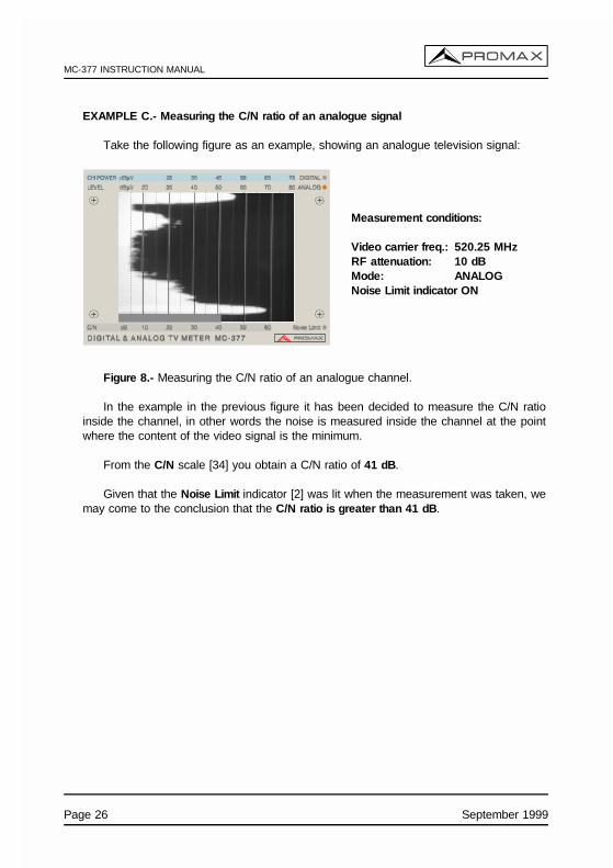
EXAMPLE C.- Measuring the C/N ratio of an analogue signal
Take the following figure as an example, showing an analogue television signal:
Measurement conditions:
Video carrier freq.: 520.25 MHzRF attenuation: 10 dBMode: ANALOGNoise Limit indicator ON
Figure 8.- Measuring the C/N ratio of an analogue channel.
In the example in the previous figure it has been decided to measure the C/N ratioinside the channel, in other words the noise is measured inside the channel at the pointwhere the content of the video signal is the minimum.
From the C/N scale [34] you obtain a C/N ratio of 41 dB.
Given that the Noise Limit indicator [2] was lit when the measurement was taken, wemay come to the conclusion that the C/N ratio is greater than 41 dB.
Page 26 September 1999

MC-377 INSTRUCTION MANUAL
4.2.5.3.2 Measuring the C/N ratio of digital channels
The C/N ratio of digital channels is measured in a similar way to analogue signals, butremember that for the instrument to interpret the signal as being digital you should selectthe digital signal measurement mode: simply, the DIG key [11] should be in the pressedposition and the DIGITAL indicator [30] should remain lit.
EXAMPLE D.- Measuring the C/N ratio of a digital channel
Audio control [27] released. Audio control [27] pressed.
Measurement conditions:
Frequency : 650.00 MHzRF attenuation: 0 dBNoise limit indicator ON
Figure 9.- Measuring the C/N ratio of a digital channel.
The previous figure shows the image appearing on the monitor when the audio control[27] is released (left) and when it is pressed (right, showing the C/N measurement bar).You are advised to adjust the SPAN control [23] so that there is no C/N measurement bar,as this may mask a signal from a lower adjacent channel and spoil the measurement.
From the C/N scale [34] (grey background) you obtain a C/N ratio of 21 dB.
Given that the Noise Limit indicator [2] was lit when the measurement was taken, wemay come to the conclusion that the C/N ratio is greater than 21 dB.
September 1999 Page 27

MC-377 INSTRUCTION MANUAL
Page 28 September 1999

MC-377 INSTRUCTION MANUAL
5 MAINTENANCE
5.1 Operating recommendations
One of the more common causes of breakdowns in TV signal level meters is thegeneration of internal short-circuits due to the introduction of small conductors. Theseconductors tend to be coaxial cable shielding wire, you are therefore advised TO NOT CUTCOAXIAL CABLES OVER THE INSTRUMENT.
5.2 Fuses replacement
5.2.1 Mains fuse replacement
The fuseholder lid is placed in the mains base and it is the voltage selector. Seefigure 1 Selection of mains voltage, paragraph 3.1.1 Selecting the mains operating voltage.
To substitute the fuse, disconnect the power cord.
With an appropriate screw driver remove the fuseholder lid.
Substitute the melt fuse for another with following characteristics:
IMPORTANT
FUSE TYPE SHOULD BE 5 x 20 mm AND:
2 A T 250 V FOR 220, 230/240 V3.15 A T 250 V FOR 110 AND 125 V
AVOIDING THESE DIRECTIONS COULD DAMAGE THE EQUIPMENT
When inserting the fuseholder lid be careful that the voltage selector is in the correctposition according to the mains.
5.2.2 Internal fuses which user cannot replace
The following fuse is found on the base board. Its location identification andcharacteristics are the following:
F1, 5 A F 63 V SMD
September 1999 Page 29
MC-377 INSTRUCTION MANUAL
5.3 Battery replacement
The battery should be replaced when you notice that its capacity, once it has beencharged, has decreased considerably (its mean life is of some 4 years). To change thebattery follow next procedure.
With the instrument off and disconnected from the mains:
- Remove the securing screws from the upper and lower covers (6 screws on eachcover). Remove the 2 covers.
- Disconnect the battery connection terminals.
- Place the instrument face down so you can see the underside of the base board.Remove the screw securing the battery holder to the base board, this screw isfound located on the base board next to the rear panel of the instrument.
- Remove the screws securing the battery holder to the rear panel of the instrument(4 screws and their respective washers and grover washers). The battery holderwill now be freed.
- Take out the battery together with the holder antiacid protector. Place the antiacidprotector on the new battery and insert it into the holder. Take the utmost care tonot invert the polarity when putting in place.
- Secure the battery holder to the rear panel (4 screws and their respective washersand grover washers).
- Secure the battery to the base board using the screw and serrated washer.
- Reconnect the battery: red cable to the positive terminal (+), black cable to thenegative terminal (-).
- Finally, secure the upper and lower covers with the respective screws andwashers.
VERY IMPORTANT
AVOID ANY TYPE OF SHORT CIRCUIT AMONG THE CABLES CONNECTED TO THEBATTERY, SINCE THE RESULTING HIGH CURRENT MAY CAUSE SERIOUS DAMAGETO THE EQUIPMENT.
Page 30 September 1999

MC-377 INSTRUCTION MANUAL
5.4 Cleaning recommendations
CAUTION
TO CLEAN THE COVER, TAKE CARE THE INSTRUMENT IS DISCONNECTED.
CAUTION
DO NOT USE SCENTED HYDROCARBONS OR CHLORIZED SOLVENTS. SUCHPRODUCTS MAY ATTACK THE PLASTICS USED IN THE CONSTRUCTION OF THECOVER.
The cover should be cleaned by means of a light solution of detergent and waterapplied with a soft cloth.
Dry thoroughly before using the system again.
September 1999 Page 31

MC-377 INSTRUCTION MANUAL
Page 32 September 1999

MC-377 INSTRUCTION MANUAL
APPENDIX A. DIGITAL TV SIGNALS
Terrestrial Digital Television (abbreviated as TDT) uses COFDM modulation (CodedOrthogonal Frequency Division Multiplex) which possesses the main feature of immunityto multi-path reflections.
Whereas the greater part of the power of an analogue channel is centred around the videocarrier, digital signals distribute their energy across the entire channel bandwidth. Thisdifference has important consequences when measuring the power of the channel.
TDT channels usually transmit 5 different TV programmes with their corresponding audiosignals and other data, in this same bandwidth an analogue modulation can only transmita single TV programme and its corresponding audio signal. Furthermore, due to the greaterefficiency of digital modulation, some 20 dB less power is needed for the same cover asan analogue signal: therefore, a digital signal with a power of 40 dBµV at the receiver inputis equivalent to a level of 60 dBµV for analogue signals. On the other hand TDT receiversrequire a minimum C/N value of between 19 and 26 dB in order to correctly decode asignal, as opposed to the 43 dB necessary for analogue signals.
In the case of individual TDT installations without signal amplifiers, it is usually enough totest the power of the signal at the input. On the other hand, in collective TDT installationswith signal amplifiers (which increase the noise level by adding the noise they generate)it is also necessary to measure the C/N ratio to guarantee signal quality.
Satellite band uses QPSK modulation (Quaternary Phase Shift Keying) which as with alldigital TV signals uniformly spreads its energy across the entire band.
Digital channels in the satellite band are classified according to their bandwidth into broador narrow band channels. Channel bandwidth is uniquely related to Symbol Rate. Thisparameter can take many values. Symbol Rate values of the order of 27.500 MBauds arecommon for broad channels and of the order of 5.000 MBauds for narrow channels.Naturally enough, the information transmitted across narrow channels is more limited.
In satellite band, relying solely on measuring power can be deceptive, as signal qualitydepends in great measure on the noise introduced by the LNB. It is therefore necessaryto measure the C/N ratio. For the purposes of orientation and digital channels a C/N ratioof approximately 8 dB may be sufficient for a Symbol Rate of 27.500 MBauds, orapproximately 2.3 dB for a Symbol Rate of 5.000 MBauds.
September 1999 Page 33

MC-377 INSTRUCTION MANUAL
MEASURING THE POWER OF DIGITAL CHANNELS
As we have already mentioned, digital signals distribute their energy uniformly across theentire bandwidth of the channel, therefore measuring the power of digital channels dependson the channel Bandwidth or the Symbol Rate (the other modulation parameters do notaffect this measurement).
The MC-377 gives power measurements for digital channels under the precision specifiedfor terrestrial signals of a bandwidth of 7.607 MHz and for satellite signals of a bandwidthcorresponding to a Symbol Rate of 27.500 MBauds. Measurements on channels made withcharacteristics different from these should be manually corrected as described below.
TDT power for bandwidths other than 7.6 MHz
Terrestrial digital channels can have bandwidths of 7.607 / 6.65 / or 5.70 MHz dependingon the channelling in each country (these bandwidths correspond to a channel separationof 8, 7 and 6 MHz respectively).
Power measurements made on terrestrial digital channels with a Bandwidth other than7.607 MHz should be corrected according to the following table.
BANDWIDTH [MHz] CORRECTION [dB]6.656250 - 1 5.705357 - 2
Therefore, for example, the power measurement of a digital channel of 6.65 MHz shouldhave 1 dB subtracted from the reading obtained by the MC-377.
SDT power for Symbol Rate other than 27.500 MBauds
Power measurements made on satellite digital channels with a Symbol Rate other than27.500 MBauds should be corrected according to the following table.
SYMBOL RATE [MBauds] CORRECTION [dB]30.000 +0.522.000 -1.120.000 -1.317.180 -2.09.096 -2.65.632 -3.05.000 -3.1
Therefore, for example, the power measurement of a digital channel of 22.000 MBaudsshould have 1.1 dB subtracted from the reading obtained by the MC-377.
Page 34 September 1999
MC-377 INSTRUCTION MANUAL
TABLE OF CONTENTS
1 GENERAL . . . . . . . . . . . . . . . . . . . . . . . . . . . . . . . . . . . . . . . . . . . . . . . . . . . . . . 11.1 Description . . . . . . . . . . . . . . . . . . . . . . . . . . . . . . . . . . . . . . . . . . . . . . . . . 11.2 Specifications . . . . . . . . . . . . . . . . . . . . . . . . . . . . . . . . . . . . . . . . . . . . . . . 2
2 SAFETY RULES . . . . . . . . . . . . . . . . . . . . . . . . . . . . . . . . . . . . . . . . . . . . . . . . . 72.1 General . . . . . . . . . . . . . . . . . . . . . . . . . . . . . . . . . . . . . . . . . . . . . . . . . . . 72.2 Specific precautions . . . . . . . . . . . . . . . . . . . . . . . . . . . . . . . . . . . . . . . . . . 8
3 INSTALLATION . . . . . . . . . . . . . . . . . . . . . . . . . . . . . . . . . . . . . . . . . . . . . . . . . . 93.1 Operating on the electrical mains supply . . . . . . . . . . . . . . . . . . . . . . . . . . . 9
3.1.1 Selecting the mains operating voltage . . . . . . . . . . . . . . . . . . . . . . . . 103.2 Operating on the battery . . . . . . . . . . . . . . . . . . . . . . . . . . . . . . . . . . . . . . 11
3.2.1 Recharging the battery . . . . . . . . . . . . . . . . . . . . . . . . . . . . . . . . . . . 11
4 OPERATING INSTRUCTIONS . . . . . . . . . . . . . . . . . . . . . . . . . . . . . . . . . . . . . . 134.1 Description of the controls and elements . . . . . . . . . . . . . . . . . . . . . . . . . . 134.2 Using the level meter . . . . . . . . . . . . . . . . . . . . . . . . . . . . . . . . . . . . . . . . 17
4.2.1 Start-up . . . . . . . . . . . . . . . . . . . . . . . . . . . . . . . . . . . . . . . . . . . . . . 174.2.2 Preliminary adjustments . . . . . . . . . . . . . . . . . . . . . . . . . . . . . . . . . . 174.2.3 Spectrum Analyser operating mode . . . . . . . . . . . . . . . . . . . . . . . . . . 184.2.4 Monitor operating mode . . . . . . . . . . . . . . . . . . . . . . . . . . . . . . . . . . 204.2.5 Taking measurements . . . . . . . . . . . . . . . . . . . . . . . . . . . . . . . . . . . 20
4.2.5.1 Measuring the level of analogue signals . . . . . . . . . . . . . . . . . . 214.2.5.2 Measuring the power of digital channels . . . . . . . . . . . . . . . . . . 234.2.5.3 Measuring the C/N ratio of analogue and digital signals . . . . . . 25
4.2.5.3.1 Measuring the C/N ratio of analogue channels . . . . . . . . . 254.2.5.3.2 Measuring the C/N ratio of digital channels . . . . . . . . . . . 27
5 MAINTENANCE . . . . . . . . . . . . . . . . . . . . . . . . . . . . . . . . . . . . . . . . . . . . . . . . 295.1 Operating recommendations . . . . . . . . . . . . . . . . . . . . . . . . . . . . . . . . . . . 295.2 Fuses replacement . . . . . . . . . . . . . . . . . . . . . . . . . . . . . . . . . . . . . . . . . . 29
5.2.1 Mains fuse replacement . . . . . . . . . . . . . . . . . . . . . . . . . . . . . . . . . . 295.2.2 Internal fuses which user cannot replace . . . . . . . . . . . . . . . . . . . . . . 29
5.3 Battery replacement . . . . . . . . . . . . . . . . . . . . . . . . . . . . . . . . . . . . . . . . . 305.4 Cleaning recommendations . . . . . . . . . . . . . . . . . . . . . . . . . . . . . . . . . . . . 31
APPENDIX A. DIGITAL TV SIGNALS . . . . . . . . . . . . . . . . . . . . . . . . . . . . . . . . . . 33