Air cooled screw chiller, standard efficiency, standard sound

Legislation
Energy Efficiency
&
Chiller Developments
Andrew Keogh

‘F’ Gas Directive

• To be carried out by Accredited Companies / Certified Personnel
• Inspection Frequency
• Leaks must repaired ASAP
• Re-inspection mandatory after one month
• 3 clear inspections and period doubled
Leakage Inspections
24> 300 kg
12> 30 kg
11> 3 kg
With Leak
Detection
Without Leak
Detection
Refrigerant
Charge

• Records for each system with charge > 3 Kg
• Mandatory recovery of refrigerants
• Mandatory certification of all technicians
• Refrigerant only sold to certified personel
Other Requirements
Passed into law spring 2006
Effective July 2007
Last chance for HFC’s

Energy Performance of Buildings Directive

Performance Objectives (Air Conditioned Buildings)
Improvement Renewables
TER = Cnotional x (1 - 0.2) x (1 - 0.1) = 0.72
• Limits to extent improvements can be offset by use of renewables
• No obligation to incorporate renewables
• London target of 20% renewables
• For buildings > 1000 m2 consider:
– CHP
– Renewables
– District schemes
– Heat Pumps
EPBD

Renewables

High Capacity
Difficult to dispose of waste
Limited application
Open Loop
Ground Source

Low Capacity
Multiple boreholes / large area
No abstraction
Closed Loop
Ground Source

High capacity
Two boreholes but widely separated
Possible circuiting
Re-injection Loop
Ground Source

• 100 kW heating demand
• 85% o/all efficiency
• @ £0.025 / kwHr
• Cost is £2.94 / Hr
• CO2 emissions
– 22.8 kg / hr
• 100 kW heating demand
• System COP of 3.5
• @ £0.075 / kWHr
• Cost is £2.14 / Hr
• CO2 emissions
– 12.05 kg / Hr
Ground Source
Environmental and Economic Advantages

• 100 kW cooling demand
• A/C chiller IPLV 4.2
• @ £0.075 / kwHr
• Cost is £1.79 / Hr
• CO2 emissions
– 10.0 kg / hr
• 100 kW cooling demand
• W/C chiller IPLV of 5.5
• @ £0.075 / kWHr
• Cost is £1.36 / Hr
• CO2 emissions
– 7.67 kg / Hr
Ground Source
Environmental and Economic Advantages

Evaporator
Plate HX’er
To LoadFrom Load
Heating
Condenser
Ground Source

Evaporator
Plate HX’er
To LoadFrom Load
Condenser
Cooling
Ground Source

20 – 300 kW Cooling
25 – 400 kW Heating
R407C
Minimum CW 5 deg C
Maximum HW 50 deg C
Cooling / Heating control
30RW Range
Ground Source
Equipment

250 – 1300 kW Cooling
300 – 1500 kW Heating
R134a
Minimum CW 5 deg C
Maximum HW 60 deg C
Cooling / Heating control
Equipment
Ground Source
30HXC Range


• Site space ?
• Is water available ?
• How much and at what temperature ?
• Apply for drilling license
– Up to 6 weeks
– Commence drilling ~ 6 weeks
– Construct well head
• Apply for abstraction license (EA)
– 3 stage process including thermal modelling
– Up to 6 months
– Cannot use well until license received (can commission)
• Cost
– 20 l/s bore hole (Shrewsbury) Approximately £ 250,000
Ground Source
Challenges

Electrical Load
Heating Load
Engine GeneratorCooling
Tower
Absorption
ChillerCooling Load
HX
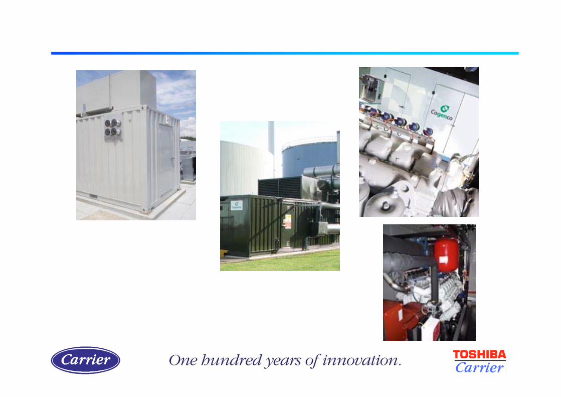
CHP with Conventional Chiller
Absorption and CHP

• Hot water 16LJ
• 264 - 1846 kW
• 110 – 75 deg C
• < 35 deg C
• > 6 deg C
• COP 0.7
Absorption and CHP

Selection Considerations
222 kW30 – 35 deg C90 – 80 deg C
255 kW33 – 38 deg C98 – 90 deg C
229 kW38 – 43 deg C110 – 100 deg C
Cooling DutyMaximum Cooling Water
(In / out)
Hot Water
(In / out)
16LJ-11 12/6 deg C

UTC Power
Direct Fired Absorption
Chiller - HeaterMicro Gas Turbines
Gas Pressure
Booster
Exhaust Gas
Ducting

240M 300M 360M
• Four microturbines (227 kW)
• LiBr double effect chiller
• 389 kW cooling
• 333 kW hot water (60 C)
• Five microturbines (284 kW)
• LiBr double effect chiller
• 486 kW cooling
• 420 kW hot water (60 C)
• Six microturbines (341 kW)
• LiBr double effect chiller
• 584 kW cooling
• 500 kW hot water (60 C)
Scalable, Flexible, Efficient Solutions
UTC Power

Facility:
57,000 Sqft A&P Supermarket, Mt. Kisco, NY
Project Sponsors:
UTC Power
DOE/Oak Ridge National Laboratory
Utility:
Con Edison
A&P Supermarket

“Pre-Assembled” Integrated System:
• Skid Mounted
• 4 - 60 kW microturbines
• Gas Compressors
• Carrier Double Effect Absorption Chiller
• Cooling Tower
• Chilled Water Pumping System
• Provides
– 240 kW of Electricity at 460v
– and 422 kW of Chilled water (35 C day)
– or 280 kW Hot water (0 C day)
Pure Comfort 240M for A&P

Microturbines
Gas Compressors
Chiller
PumpStation
Cooling Tower
ChilledWater
Connections
Electrical Panels /Pump Controls
Exhaust Manifold
60’
12’
6”
Chiller Exhaust /Desiccant Connection
Pure Comfort 240M Skid

Microturbines
Carrier DoubleEffect Absorber
HeatedEnclosure
Cooling Tower
Gas Compressors
Exhaust Duct
Exhaust Diverter Valve
Pure Comfort 240M Skid

Chilled Water Pump
Cooling Tower
Cooling Water Pump
Air-Cooled Condenser
Vapor Compression
Refrigeration Cycle
Waste Heat Driven
LiBr/H2O Absorption Cycle
Refrigerant
Sub-Cooler
Desiccant
System
Ambient
Air
System Integration

UTC Power

PURECELLTM 200
Benefits:
Ultra Clean Emissions
– Virtually pollution free
– Meets CARB 2007
Reliable Power
– Highest assurance of uninterrupted power
High Efficiency
– 37% average electrical efficiency
– Over 80% efficient with heat recovery
Quiet operation
– Low sound profile
Remote Monitoring Capability
Features:
• 200 kW electrical power
• 270 kW heat output
• Fuel Choices:
– Natural Gas
– Anaerobic digester gas (ADG)
– Dual fuel
Emerging technology
High cost
Limited life

PURECELLTM 200
Fuel reformer
Power conditioner
Cell stack
Electronics and
controls
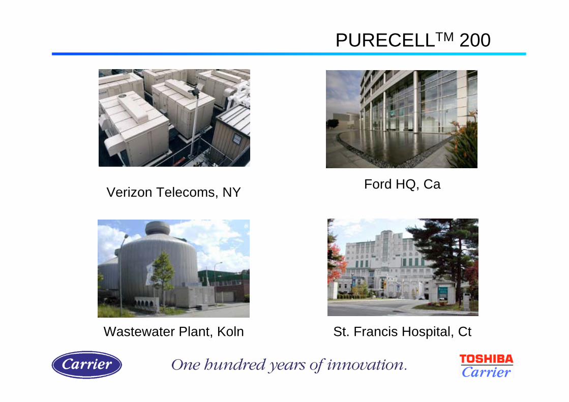
Verizon Telecoms, NYFord HQ, Ca
St. Francis Hospital, CtWastewater Plant, Koln
PURECELLTM 200

Fuel Cell(2 off)
265 kW
Total
80 C90 C
400 kW
Electrical
Power
(total)
Gas
Input
Low
Temperature
Hot Water
Cooling
Water
30 C
35 C
Absorption
ChillerChilled
Water
6 C
12 C
High
Temperature
Hot Water
Fuel Cell and Absorption

Performance Objectives (Air Conditioned Buildings)
Improvement Renewables
TER = Cnotional x (1 - 0.2) x (1 - 0.1) = 0.72
• Limits to extent improvements can be offset by use of renewables
• No obligation to incorporate renewables
• London target of 20% renewables
• For buildings > 1000 m2 consider:
– CHP
– Renewables
– District schemes
– Heat Pumps
EPBD

Compliance Guide

• Carbon calculations can be undertaken using a variety of
programs:
– Tas
– Hevacomp
– IES
– Cymap
• The Simplified Building Efficiency Model (SBEM) is another
way to show compliance.
• The Compliance Guide contains information on determining
the efficiency of the AC system to be input into the calculation
program.
Compliance Guide

• If no part load data available the full load EER is used as the SEER
• Estimated SEER for a single chiller serving an office building
SEER = 0.20*EER25 + 0.36*EER50 + 0.32*EER75 + 0.12*EER100
• Estimated SEER for a single chiller serving a.n. other building
SEER = 0.25*EER25 + 0.25*EER50 + 0.25*EER75 + 0.25*EER100
Compliance Guide
•SEER (Seasonal Energy Efficiency Ratio)
= Total amount of cooling summed over year
Total energy input

Seasonal Energy Efficiency Ratio
Load % Time % OAT °C EER
100 12 35 3.08
75 32 30 3.91
50 36 25 4.44
25 20 20 5.64
SEER 4.35
Part L SEER - Office
Compliance Guide
Chilled water 12/7 C

Compliance Guide
Multiple Chiller Systems
‘For a system with multiple chillers for use in office buildings, combined
EER values may be calculated based on the sum of the energy
consumptions of all the operating chillers. In this case care must be
taken to include all of the factors that can influence the combined
performance of the multiple chiller installtion. This will include:
Degree of oversizing of the total installed capacity
Sizing of individual chillers
EER’s of individual chillers
Control mode; e.g. parallel or sequential
Load profile of the proposed cooling load
Where these are known it may be possible to calculate a SEER which
matches more closely the proposed installation than the simplifications
described earlier.’

System Performance
0
500,000
1,000,000
1,500,000
2,000,000
2,500,000
100 92 85 77 69 61 54 46 38 30 23 15
% Building Load
kW
Hrs
Co
oli
ng
/ Y
ea
r
0.00
1.00
2.00
3.00
4.00
5.00
6.00
7.00
Sy
ste
m E
ER
kWHrs Cooling/year
System EER
Compliance Guide

Seasonal Energy Efficiency Ratio
Load % Time % OAT °C EER
100 12 35 3.08
75 32 30 3.91
50 36 25 4.44
25 20 20 5.64
Single chiller SEER 4.35
Part L SEER - Office
Actual SEER 5.62
Compliance Guide
Project
chilled
water
conditions

Compliance Guide
1.0Gas fired VRF
0.5Absorption cycle chillers
3.2Water loop heat pumps
2.25Air cooled chillers
3.4Water cooled chillers
2.4Splits, multi-splits and VRF
2.2Other types
1.8Single duct
types
Packaged air
conditioners
Minimum Full Load
EER
Type
Standard Rating Conditions

Chiller design
Selection considerations
New technology
Energy Efficiency

R11
R12
CFC
R22
R123
HCFC
R32
R134a
R125
R143a
HFC
R717
R290
H2O
CO2
Natural
Pure Fluids
R407c
R404a
Zeotropes
R502
R507
R410a
Azeotropes
Mixtures
Refrigerants
Alternative Refrigerants

Evaporative Heat Transfer Performance
4
4.5
5
5.5
6
6.5
7
7.5
8
0.2 0.3 0.4 0.5 0.6 0.7 0.8
Quality
He
at
Tra
nsfe
rfi
R22
R410A
R134a
R407C
Liquid Vapour
Heat Transfer

12 sizes from 250-760 kW
R410A
8 sizes from 250-465 kW
FL FL
H
C
R32
H
R125
H
FL
FL
FL
FL
C CFL
30RB / 30RQ

UK Specification

• Office Application– 6/12 chilled water, 35 Ambient
– Full load EER 2.59
– Part L SEER 3.50
• 1000 kW system, 2 units
– Max load 950 kW
– Min load 200 kW
– Mon – Fri 07:00 – 18:00
– Sat 07:00 – 13:00
– London weather data
• SEER 4.8
• Data Centre– 10/16 chilled water, 35 ambient
– Full load EER 2.76
– Part L SEER 3.63
• 1000 kW system, 2 units
– Max load 950 kW
– Min load 800 kW
– 24hr / day, 365 days / year
– London weather data
• SEER 5.65
30RB0522

20 sizes from 268-1605 kW
R134a
FL H
FL
FL FL
C C
H
30XA
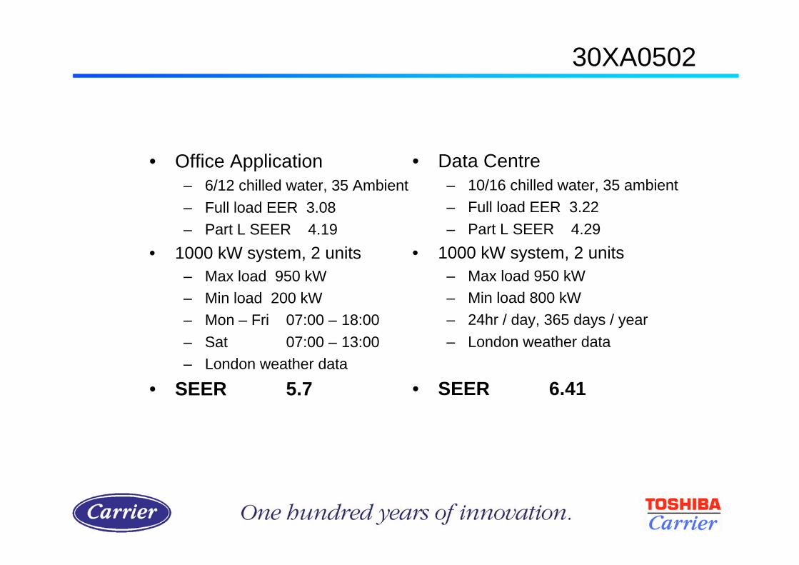
• Office Application
– 6/12 chilled water, 35 Ambient
– Full load EER 3.08
– Part L SEER 4.19
• 1000 kW system, 2 units
– Max load 950 kW
– Min load 200 kW
– Mon – Fri 07:00 – 18:00
– Sat 07:00 – 13:00
– London weather data
• SEER 5.7
• Data Centre
– 10/16 chilled water, 35 ambient
– Full load EER 3.22
– Part L SEER 4.29
• 1000 kW system, 2 units
– Max load 950 kW
– Min load 800 kW
– 24hr / day, 365 days / year
– London weather data
• SEER 6.41
30XA0502

30HXC
R134a
FL H
FL
FL FL
C C
H
17 sizes from 296-1300 kW

• Office Application
– 6/12 chilled water, 27/32 cooling water
– Full load EER 4.75
– Part L SEER 5.25
• 1000 kW system, 2 units
– Max load 1000 kW
– Min load 200 kW
– Mon – Fri 07:00 – 18:00
– Sat 07:00 – 13:00
– London weather data
• SEER 6.2 (chillers only)
• SEER 4.42 (inc. pumps and towers)
• Data Centre
– 10/16 chilled water, 27/32 cooling water
– Full load EER 5.35
– Part L SEER 6.34
• 1000 kW system, 2 units
– Max load 1000 kW
– Min load 800 kW
– 24hr / day, 365 days / year
– London weather data
• SEER 7.27 (chillers only)
• SEER 5.22 (inc pumps and towers)
30HXC
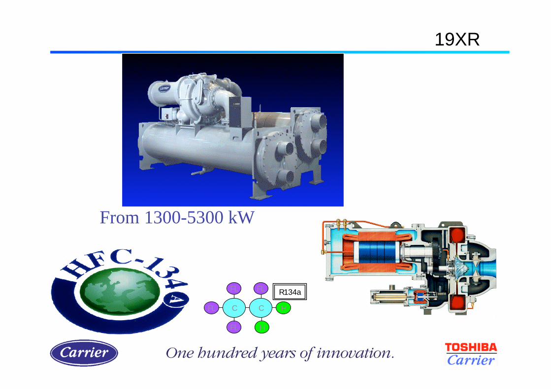
19XR
R134a
FL H
FL
FL FL
C C
H
From 1300-5300 kW

• Office Application
– 6/12 chilled water, 27/32 cooling water
– Full load EER 5.40
– Part L SEER 5.28
• 3000 kW system, 2 units
– Max load 3000 kW
– Min load 600 kW
– Mon – Fri 07:00 – 18:00
– Sat 07:00 – 13:00
– London weather data
• SEER 6.7 (chillers only)
• SEER 4.6 (inc pumps and towers)
• Data Centre
– 10/16 chilled water, 27/32 cooling water
– Full load EER 6.41
– Part L SEER 6.38
• 3000 kW system, 2 units
– Max load 3000 kW
– Min load 2500 kW
– 24hr / day, 365 days / year
– London weather data
• SEER 8.08 (chillers only)
• SEER 5.6 (inc pumps and towers)
19XR

Typical Temperature Profile
0
100
200
300
400
500
600
0.3 3.1 5.8 8.6 11.4 14.2 16.9 19.7 22.5 25.3 28.1
Bin Temperature (deg C)
Ho
urs
(3150 operating hours)
Design Optimisation

Temperature > 25 deg C
68 hours (< 1 %)
Satisfy comfort levels for 99 % of the year
Traditionally design for 32-40 deg C
Design Optimisation
Design Optimisation

Typical System Profile
0
100
200
300
400
500
600
0.3 3.1 5.8 8.6 11.4 14.2 16.9 19.7 22.5 25.3 28.1
Bin Temperature (deg C)
Ho
urs
0.0
100.0
200.0
300.0
400.0
500.0
600.0
kW
Hours
Cooling Load
(3150 operating hours)
Design Optimisation

Hydronic system
Improvement
REFRIGERANT
PUMP
Thermosiphon system

Air to Water Heat Pumps
+
Boiler
Heat Pump
Chiller
3 kW of heat for 1 kW input
Single unit for cooling and heating
Other Opportunities

• Free generation of hot water
(when chiller is running)
• Total heat recovery condenser
(Hot water up to 55°)
• Partial heat recovery desuperheater
(Hot water up to 70 °)
Other Opportunities
Heat Recovery

MICRO
CHANNELS
TUBES
MANIFOLD
FINS
Coil DesignCoil Construction

Coil MCHX
Coil corrosion after 5000 hr CM-1 test
Coil RTPF
MCHX Significantly Better
Coil Construction

• Improved galvanic corrosion resistance
• Reduced refrigerant charge : -30%
• Reduced weight: - 50%
• Reduced clogging in sandy environments
• Easy to clean
• Increased capacity / efficiency
Coil Construction
MCHX Advantages

New emphasis
New legislation
New products
New ways of working
Summary

Thank you
Questions
?