LED Pin Light - Brunswick Bowling · 4 LED Pin Lighting safety Notice to Users of this MaNUal This...
26
LED Pin Light Installation, Pre-Installation & Operation Manual December 2012/ 47-902714-000
Transcript of LED Pin Light - Brunswick Bowling · 4 LED Pin Lighting safety Notice to Users of this MaNUal This...

1 LED Pin Lighting
LED Pin Light
Installation, Pre-Installation & Operation Manual
December 2012/ 47-902714-000

LED Pin Lighting2
LED Pin Light Installation, Pre-Installation & Operations Manual
© December 2012 by the Brunswick Bowling and Billiards Corporation. All rights reserved.
GS-Series and Pinball Wizard are registered trademarks of the Brunswick Bowling and Billiards Corporation.
Reorder Part No. 47-902714-000
Notice: If available, updates to this manual can be found on-line at www.brunswickbowling.com.
Confidential proprietary information. All information contained in this document is subject to change without notice.
Brunswick Bowling and Billiards Corporation525 West Laketon AvenueP.O. Box 329Muskegon, MI 49443-0329U.S.A.
231.725.3300

3 LED Pin Lighting
SafetyNotes aNd WarNiNgThroughout this publication, “Warnings” and “Cautions” (accompanied by one of the International HAZARD Symbols) are used to alert the mechanic to special instructions concerning a particular service or operation that may be hazardous if performed incorrectly or carelessly. They are defined below. OBSERVE AND READ THEM CAREFULLY!
These “Safety Alerts” alone cannot eliminate the hazards that they signal. Strict compliance to these special instructions when performing the service, plus training and “Common Sense” operation are major accident prevention measures.
NOTE or IMPORTANT!: Willdesignatesignificantinformationalnotes.
WARNING! Will designate a mechanical or nonelectrical alert which could potentially cause
personal injury or death.
WARNING! Will designate electrical alerts which could potentially cause personal injury or death.
CAUTION! Will designate a mechanical or nonelectrical alert which could potentially cause
product damage.
Will designate grounding alerts.

LED Pin Lighting4
safety Notice to Users of this MaNUalThis manual has been written and published by the Service Department of Brunswick Bowling and Billiards to aid the reader when servicing or installing the products described.
It is assumed that these personnel are familiar with, and have been trained in, the servicing or installation procedures of these products, which includes the use of common mechanic’s hand tools and any special Brunswick or recommended tools from other suppliers.
We could not possibly know of and advise the reader of all conceivable procedures by which a service might be performed and of the possible hazards and/or results of each method. We have not attempted any such wide evaluation. Therefore, anyone who uses a service procedure and/or tool, which is not recommended by Brunswick, must first completely satisfy himself that neither his nor the product’s safety will be endangered by the service procedure selected.
All information, illustrations and specifications contained in this manual are based on the latest product information available at the time of publication.
It should be kept in mind, while working on the product, that the electrical system is capable of violent and damaging short circuits or severe electrical shocks. When performing any work where electrical terminals could possibly be grounded or touched by the mechanic, the power to the product should be disconnected prior to servicing and remain disconnected until servicing is complete.

5 LED Pin Lighting
Table of ContentsPackaging ..................................................................................................................................6Pre-Installation .........................................................................................................................9 Installation LED Pin Lighting ..............................................................................................11
GS-X LED Pin Light Brackets .......................................................................................... 11A-2 LED Pin Light Brackets ............................................................................................. 14String Pin Light Brackets .................................................................................................. 17LED Pin Light MOUNTING ............................................................................................. 18Cabling & Power ............................................................................................................... 20
Communication CABLES ........................................................................................................................... 20Addressing ......................................................................................................................... 22
Operation ..................................................................................................................................................... 22Setting the Address of the LED Pin Light ................................................................................................... 23

LED Pin Lighting6
PackagingPage 1 of 1
MODEL NUMBER CONFIGURATIONBRUNSWICK BOWLING & BILLIARDS CORPORATION
Drawing Number: G6-300001-000 Rev. No: N/C
REV. QTY. PART NUMBER
1.00 47-863001-000 PKG. - LED LIGHT FIXTURE1.00 47-863002-000 PKG. - DMX CABLE, 10'
DESCRIPTION: MNC - PIN DECK LED LIGHTING, LED LIGHT
DESCRIPTION OF PACKAGE
Page 1 of 1
MODEL NUMBER CONFIGURATIONBRUNSWICK BOWLING & BILLIARDS CORPORATION
Drawing Number: G6-300002-000 Rev. No: N/C
REV. QTY. PART NUMBER
1.00 47-863003-000 PKG. - CONTROLLER FOR PIN DECK LIGHTING, 110V1.00 47-902714-000 MANUAL - LED PIN LIGHT PRE-INSTALLATION, INSTALLATION
& OPERATION
DESCRIPTION: MNC - PIN DECK LED LIGHTING, DMX CONTROLLER, 110V
DESCRIPTION OF PACKAGE
Page 1 of 1
MODEL NUMBER CONFIGURATIONBRUNSWICK BOWLING & BILLIARDS CORPORATION
Drawing Number: G6-300003-000 Rev. No: N/C
REV. QTY. PART NUMBER
1.00 47-863004-000 PKG. - CONTROLLER FOR PIN DECK LIGHTING, 230V1.00 47-902714-000 MANUAL - LED PIN LIGHT PRE-INSTALLATION, INSTALLATION
& OPERATION
DESCRIPTION: MNC - PIN DECK LED LIGHTING, DMX CONTROLLER, 230V
DESCRIPTION OF PACKAGE
7 LED Pin Lighting
Page 1 of 1
MODEL NUMBER CONFIGURATIONBRUNSWICK BOWLING & BILLIARDS CORPORATION
Drawing Number: G6-300004-000 Rev. No: N/C
REV. QTY. PART NUMBER
1.00 47-863005-000 PKG. - DMX CABLE, 150'
DESCRIPTION: MNC - PIN DECK LED LIGHTING, HOME RUN CABLE
DESCRIPTION OF PACKAGE
Page 1 of 1
MODEL NUMBER CONFIGURATIONBRUNSWICK BOWLING & BILLIARDS CORPORATION
Drawing Number: G6-300005-000 Rev. No: N/C
REV. QTY. PART NUMBER
1.00 47-862933-000 PKG. - PIN DECK LIGHT MOUNTING BRACKETS
DESCRIPTION: MNC - PIN DECK LED LIGHTING, GSX MOUNTING BRACKET
DESCRIPTION OF PACKAGE
Page 1 of 1
MODEL NUMBER CONFIGURATIONBRUNSWICK BOWLING & BILLIARDS CORPORATION
Drawing Number: G6-300006-000 Rev. No: N/C
REV. QTY. PART NUMBER
1.00 47-863006-000 PKG. - DMX CABLE, 25'
DESCRIPTION: MNC - PIN DECK LED LIGHTING, 25' EXTENSION CABLE
DESCRIPTION OF PACKAGE
Page 1 of 1
MODEL NUMBER CONFIGURATIONBRUNSWICK BOWLING & BILLIARDS CORPORATION
Drawing Number: G6-300007-000 Rev. No:
REV. QTY. PART NUMBER
1.00 12-860812-000 PKG. - BRACKETS, A2 PIN DECK LIGHT, W/HDWR.
DESCRIPTION: MNC - BRACKETS, A2 PIN DECK LIGHT
DESCRIPTION OF PACKAGE

LED Pin Lighting8
Page 1 of 1
MODEL NUMBER CONFIGURATIONBRUNSWICK BOWLING & BILLIARDS CORPORATION
Drawing Number: G6-300009-000 Rev. No: N/C
REV. QTY. PART NUMBER
1.00 55-860034-000 PKG. STRING PINDECK LIGHT GUARD & MOUNT HDWR.1.00 55-860026-000 MOUNTING BRACKET & HARDWARE FOR LED PINDECK
LIGHT, STRINGPIN
DESCRIPTION: MNC - STRING PIN MOUNTING BRACKETS & GUARDS FOR LED PIN LIGHT
DESCRIPTION OF PACKAGE

9 LED Pin Lighting
Pre-InstallationLED Pin Light, 47-863001-000
Volts Hertz AC/DC Phase Amps Per Unit
Watts Branch Circuit Customer's Responsibility
100-130 50/60 ac 1 0.5 60 2 wires + ground No more than 12 lights daisy chained in series
200-240 50/60 ac 1 .25 60 2 wires + ground No more than 12 lights daisy chained in series
(1) POWER INPUT - 120-240Vac, 5 amp (2) FUSE - 100-240Vac, 2 amp (3) MIC VOLUME - Not Used (4) MIC - Not Used (5) COMMUNICATION INPUT PORT - connection for the communication cable from the deck light controller or the previous led pin light (6) COMMUNICATION OUTPUT PORT - connection for the cable to continue the communication to additional pin lights (7) DIP SWITCH CLUSTER- switches used to set the id address of pinlight.
IMPORTANT!:Therewillneedtobeanewoutlet/circuitper12lanes.TheoutletontheLEDpinlightisonlyratedfor5amps.

LED Pin Lighting10
Controller, 47-863003-000Volts Hertz AC/DC Phase Amps
Per UnitWatts Branch Circuit Customer's
Responsibility100-130 50/60 ac 1 .1 120 2 wires + ground No more than 12 lights
daisy chained in series200-240 50/60 ac 1 0.5 120 2 wires + ground No more than 12 lights
daisy chained in series
(1) POWER SUPPLY SELECTOR SWITCH - Use to select power to controller from the "UsB" Power Port (2) or the "eXt" dc Voltage Port (3). Needs to be set to "EXT" (3) (2) USB POWER PORT - Not Used (3) DC VOLTAGE PORT - Not Used (4) I/O PORT- Not Used IMPORTANT!:Programnumbers15,16and24willNOToperatewithvectorcameras.Theprograms
willcausemis-scoringwithVectorscoring.

11 LED Pin Lighting
Installation LED Pin Lightinggs-X led PiN light BracketsIf the GS-X Pinsetter has an attached wire way on the front of the machine perform step1, if pinsetter is not equipped with a wire way proceed to step2.
1. Remove one of the two M8 screws and nuts (Left Hand side of the machine) securing the wire way to the pinsetter.
Figure1
LED Pin Lighting12
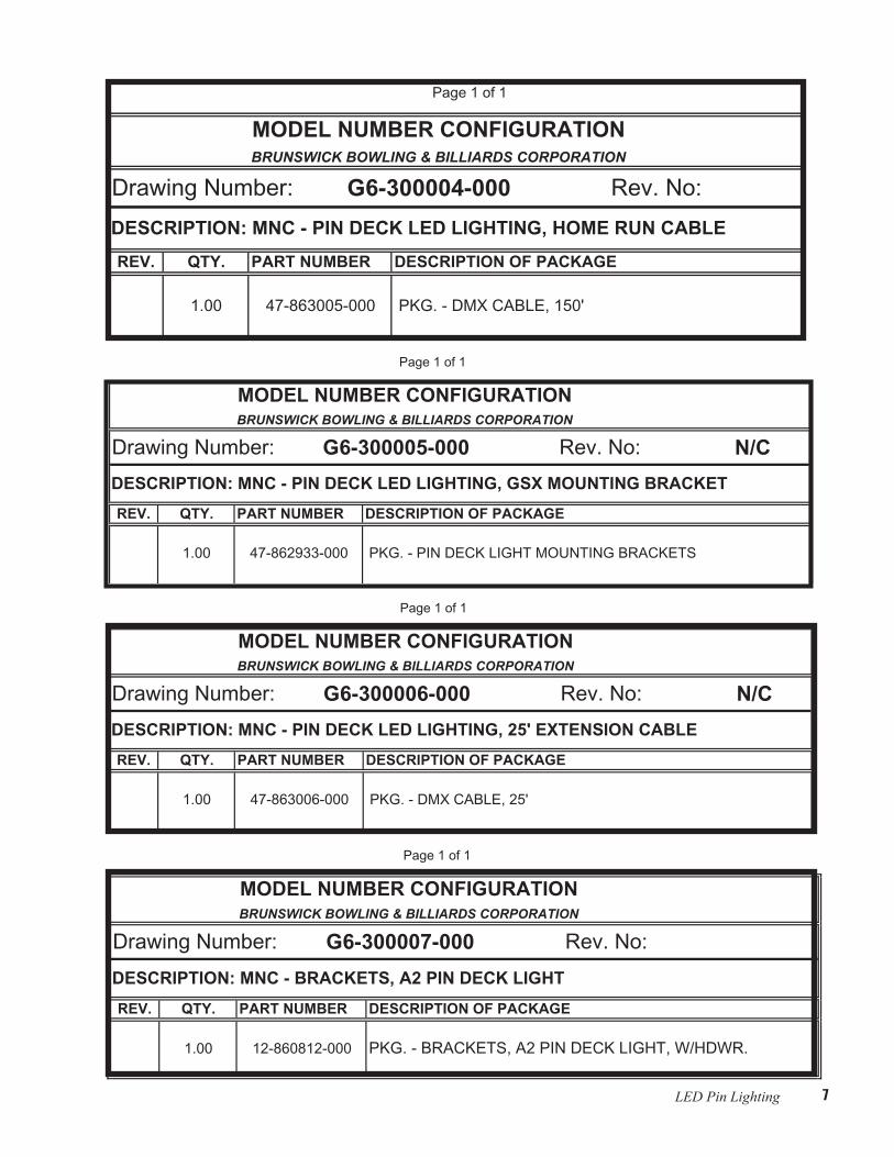
2. Insert the stud of Left Hand Bracket (47-086148-009) into the hole left by hardware removal in previous step and secure it with M8 nut (11-051744-001). Refer to Figure2.
Figure2
3. Remove the Right Hand side M8 screw and nut securing the wire way to the pinsetter. Refer to Figure 1.

13 LED Pin Lighting
4. Insert the stud of Right Hand Bracket (47-086149-009) into the hole left by hardware removal in previous step and secure it with M8 nut (11-051744-001). Refer toFigure3.
Figure 3
LED Pin Lighting14
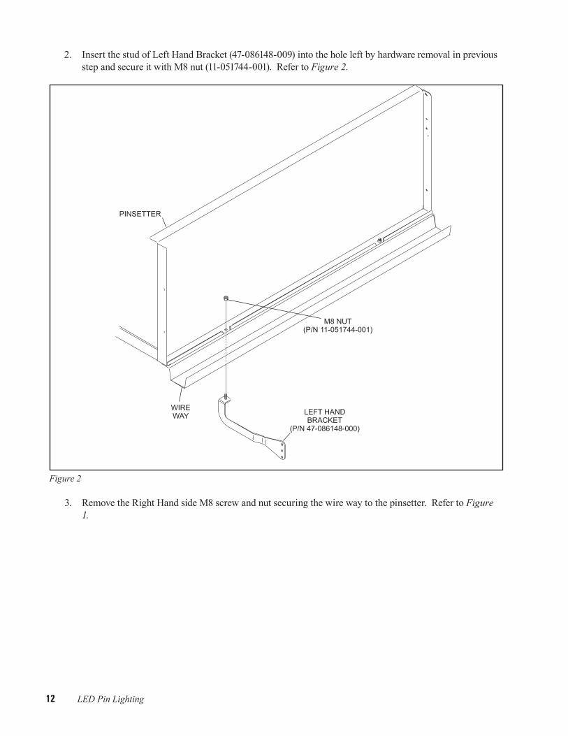
a-2 led PiN light Brackets 1. Find the center of the existing A-2 pin light support. Refer to Figure4.
Figure4
2. Position 1 bracket (12-610001-000) 20" to the left of the center line of the pin light support and one bracket 20" to the right of the center line of the pin light support. Bracket must extend toward foul line. Refer to Figures4&5.

15 LED Pin Lighting
Figure5 3. Thread a 1/4-20 x 1" socket head set screw (11-103171-009) in the nut on the front (toward the foul line)
side and tighten to secure the bracket to the pin light support. Refer to Figure6.

LED Pin Lighting16
Figure6
4. Thread a 1/4-20 hex nut (11-125100-009) onto the set screw and tighten to lock set screw.
5. Thread a 1/4-20 x 1" socket head set screw (11-103171-009) in each of the nuts on top of the bracket. Alternately tighten the set screws until the bracket is square and perpendicular to the pin light support.
6. Thread a 1/4-20 hex nut (11-125100-009) onto the set screw and tighten to lock set screw.

17 LED Pin Lighting
striNg PiN light Brackets
Figure 7

LED Pin Lighting18
led PiN light MoUNtiNg 1. Loosely attach Pin Deck Light to brackets with (1) M6 Screw and (2) External Tooth Lockwashers on
each end of the light. Refer to Figure8.
Figure 8

19 LED Pin Lighting
2. Adjust the angle of the light to the desired position and tighten the screws on both ends of the light. Refer to Figure9.
Figure 9

LED Pin Lighting20
caBliNg & PoWer
communication caBles 1. Connect the male end of the 150' (45.72 m) home run cable to the "Communication Output" port on the
controller (P/N 47-863003-000). Refer to Figure10.
Figure10
2. Connect the female end of the home run cable to the "Communication Input" port on the first LED pin light. Refer to Figure10.
NOTE:Thehomeruncablecanbeattachedtothepinlightofeitherthefirstorlastlane.Communicationfortheremainingpinlightswilldaisychainfromthatpoint.

21 LED Pin Lighting
3. Using a 10ft/3m cable, connect the first light to the second light, the second light to the third light, etc., until all the lights are chained together. Refer to Figure11
.
Figure11
NOTE:Ifthereisalargegapbetweentwolanes,thedatacablescanbeconnectedtogethertocreatealongercable.RefertoFigure 12.
Figure12

LED Pin Lighting22
Power 1. Starting at the first or last light, plug the light into a standard electrical outlet. An adapter may need to be
used, but the light will support 90-240V 50/60 Hz. Refer to Figure13.
Figure13
2. Plug the power cable from the light on the next lane into the power plug on the light on the previous lane. Up to 12 lights may be connected together.
NOTE:Anoutletisrequiredforevery12LEDpinLights.
addressiNg
operationTo turn on the controller, plug the supplied power supply into the "DC Voltage" port and make sure the switch on the box is set to "EXT" (external power supply) not "USB" (for connecting to a computer). In order to function properly, the controller must be set to EXT. When it is set correctly and plugged in, the light indica-tors on the controller will light up. Refer to Figure14.
Figure14

23 LED Pin Lighting
To operate the controller, use the + and – buttons to switch programs. When a program is active, it will con-tinue to run until the controller box is unplugged or a different program is selected. By default, the controller will operate program 01 when it is turned on. Refer to Figure15.
Figure15
setting the address of the led Pin lightEach light has 10 dip switches used to create a unique address for the light. Switches 1-9 are used to set the unique address for each light. Switch 10 is used to enable the light for DMX operation. To set a switch to the ON position, push the switch toward the number. Push the switch away from the number to set the switch to the OFF position. Refer to Figure16.
Figure16
LED Pin Lighting24
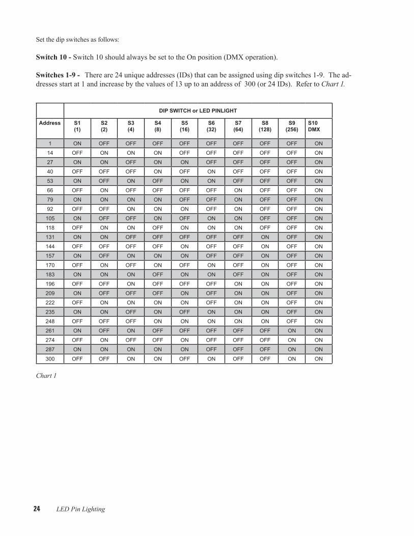
Set the dip switches as follows:
Switch 10 - Switch 10 should always be set to the On position (DMX operation).
Switches 1-9 - There are 24 unique addresses (IDs) that can be assigned using dip switches 1-9. The ad-dresses start at 1 and increase by the values of 13 up to an address of 300 (or 24 IDs). Refer to Chart1.
DIP SWITCH or LED PINLIGHT
Address S1 (1)
S2 (2)
S3 (4)
S4(8)
S5 (16)
S6 (32)
S7(64)
S8 (128)
S9 (256)
S10DMX
1 oN off off off off off off off off oN
14 off oN oN oN off off off off off oN
27 oN oN off oN oN off off off off oN
40 off off off oN off oN off off off oN
53 oN off oN off oN oN off off off oN
66 off oN off off off off oN off off oN
79 oN oN oN oN off off oN off off oN
92 off off oN oN oN off oN off off oN
105 oN off off oN off oN oN off off oN
118 off oN oN off oN oN oN off off oN
131 oN oN off off off off off oN off oN
144 off off off off oN off off oN off oN
157 oN off oN oN oN off off oN off oN
170 off oN off oN off oN off oN off oN
183 oN oN oN off oN oN off oN off oN
196 off off oN off off off oN oN off oN
209 oN off off off oN off oN oN off oN
222 off oN oN oN oN off oN oN off oN
235 oN oN off oN off oN oN oN off oN
248 off off off oN oN oN oN oN off oN
261 oN off oN off off off off off oN oN
274 off oN off off oN off off off oN oN
287 oN oN oN oN oN off off off oN oN
300 off off oN oN off oN off off oN oN
Chart1
25 LED Pin Lighting
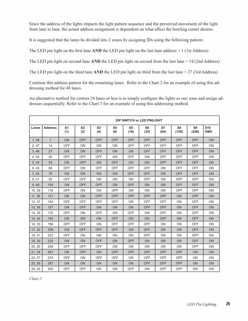
Since the address of the lights impacts the light pattern sequence and the perceived movement of the light from lane to lane, the actual address assignment is dependent on what affect the bowling center desires.
It is suggested that the lanes be divided into 2 zones by assigning IDs using the following pattern:
The LED pin light on the first lane AND the LED pin light on the last lane address = 1 (1st Address)
The LED pin light on second lane AND the LED pin light on second from the last lane = 14 (2nd Address)
The LED pin light on the third lane AND the LED pin light on third from the last lane = 27 (3rd Address)
Continue this address pattern for the remaining lanes. Refer to the Chart 2 for an example of using this ad-dressing method for 48 lanes.
An alternative method for centers 24 lanes or less is to simply configure the lights as one zone and assign ad-dresses sequentially. Refer to the Chart 3 for an example of using this addressing method.
DIP SWITCH or LED PINLIGHT
Lanes Address S1 (1)
S2 (2)
S3 (4)
S4(8)
S5 (16)
S6 (32)
S7(64)
S8 (128)
S9 (256)
S10DMX
1, 48 1 oN off off off off off off off off oN
2, 47 14 off oN oN oN off off off off off oN
3, 46 27 oN oN off oN oN off off off off oN
4, 45 40 off off off oN off oN off off off oN
5, 44 53 oN off oN off oN oN off off off oN
6, 43 66 off oN off off off off oN off off oN
7, 42 79 oN oN oN oN off off oN off off oN
8, 41 92 off off oN oN oN off oN off off oN
9, 40 105 oN off off oN off oN oN off off oN
10, 39 118 off oN oN off oN oN oN off off oN
11, 38 131 oN oN off off off off off oN off oN
12, 37 144 off off off off oN off off oN off oN
13, 36 157 oN off oN oN oN off off oN off oN
14, 35 170 off oN off oN off oN off oN off oN
15, 34 183 oN oN oN off oN oN off oN off oN
16, 33 196 off off oN off off off oN oN off oN
17, 32 209 oN off off off oN off oN oN off oN
18, 31 222 off oN oN oN oN off oN oN off oN
19, 30 235 oN oN off oN off oN oN oN off oN
20, 29 248 off off off oN oN oN oN oN off oN
21, 28 261 oN off oN off off off off off oN oN
22, 27 274 off oN off off oN off off off oN oN
23, 26 287 oN oN oN oN oN off off off oN oN
24, 25 300 off off oN oN off oN off off oN oN
Chart2

LED Pin Lighting26
DIP SWITCH or LED PINLIGHT
Lane Address S1 (1)
S2 (2)
S3 (4)
S4(8)
S5 (16)
S6 (32)
S7(64)
S8 (128)
S9 (256)
S10DMX
1 1 oN off off off off off off off off oN
2 14 off oN oN oN off off off off off oN
3 27 oN oN off oN oN off off off off oN
4 40 off off off oN off oN off off off oN
5 53 oN off oN off oN oN off off off oN
6 66 off oN off off off off oN off off oN
7 79 oN oN oN oN off off oN off off oN
8 92 off off oN oN oN off oN off off oN
9 105 oN off off oN off oN oN off off oN
10 118 off oN oN off oN oN oN off off oN
11 131 oN oN off off off off off oN off oN
12 144 off off off off oN off off oN off oN
13 157 oN off oN oN oN off off oN off oN
14 170 off oN off oN off oN off oN off oN
15 183 oN oN oN off oN oN off oN off oN
16 196 off off oN off off off oN oN off oN
17 209 oN off off off oN off oN oN off oN
18 222 off oN oN oN oN off oN oN off oN
19 235 oN oN off oN off oN oN oN off oN
20 248 off off off oN oN oN oN oN off oN
21 261 oN off oN off off off off off oN oN
22 274 off oN off off oN off off off oN oN
23 287 oN oN oN oN oN off off off oN oN
24 300 off off oN oN off oN off off oN oN
Chart 3