
lecture slides - 18 - Materials Science · – Note FeO may not coat surface ... • Adsorption –...
24
J.W. Morris, Jr. University of California, Berkeley MSE 200A Fall, 2008 Environmental Interactions • Chemical reaction between the material and its environment • Beneficial interactions: materials processing – Carburization and nitriding hardens for wear resistance – “Doping” adds electrically active species – Interfacial compounds are used as diffusion barriers • Harmful interactions – Oxidation • Materials “burn” slowly at high T – Corrosion • Electrochemical reactions oxidize near room temperature
Transcript of lecture slides - 18 - Materials Science · – Note FeO may not coat surface ... • Adsorption –...

J.W. Morris, Jr. University of California, Berkeley
MSE 200A Fall, 2008
Environmental Interactions
• Chemical reaction between the material and its environment
• Beneficial interactions: materials processing – Carburization and nitriding hardens for wear resistance – “Doping” adds electrically active species – Interfacial compounds are used as diffusion barriers
• Harmful interactions – Oxidation
• Materials “burn” slowly at high T – Corrosion
• Electrochemical reactions oxidize near room temperature

J.W. Morris, Jr. University of California, Berkeley
MSE 200A Fall, 2008
Mechanism of Parabolic Oxidation
• Diffusion through coherent oxide film – Metal is ordinarily more mobile, diffuses to oxidize at free surface – Growth is diffusion controlled – Thickness increases roughly as mean diffusion distance (<x> = √2Dt)
• Film diffusivity controls oxidation – Oxidation is a high-T phenomenon (rate increases exponentially with T) – Oxides with low D (high QD) are protective
• Film forms, but cannot growth
metal
oxide 2e - O O 2 O = MO
M ++ δ
€
δ = k t
€
k = Aexp− QD
kT

J.W. Morris, Jr. University of California, Berkeley
MSE 200A Fall, 2008
Mechanisms of Linear Oxidation
• Linear oxidation is the addition of many parabolic steps – Oxide does not fit perfectly on surface ⇒ mechanical strain – Strain increases as film thickens – At critical thickness, film ruptures, exposing fresh surface – Process repeats
• To suppress film rupture, suppress film growth – Minimize diffusion through film
δ
t

J.W. Morris, Jr. University of California, Berkeley
MSE 200A Fall, 2008
Engineering Oxidation Resistance: Alloying to Create Protective Films - Stainless Steel
• The corrosion rate of Fe decreases with Cr – Asymptotes at > 8% Cr (“stainless steel”)
• Preferential incorporation of Cr into the oxide film – Film is essentially Cr2O3 when Cr >8%.
• Protective film no better than protective oxide – Stainless steel liable to oxidation in presence of Cl (attacks Cr2O3) – Stainless steel oxidizes at sufficiently high T
ln (k)
Cr (wt%)5 10 15 20
• Influence of Cr on the oxidation rate of Fe
€
k = Aexp −QD
kT

J.W. Morris, Jr. University of California, Berkeley
MSE 200A Fall, 2008
Engineering Oxidation Resistance: Protective Coatings
• Protect high temperature structures with oxidation-resistant coatings – Ex: turbine blades in jet engines
• Properties required of a protective coating – Good oxidation resistance (Al, Cr) – Resistance to spall (fracture of coating)
• Matching coefficient of thermal expansion • Intermediate bonding layer
• Common choices: CoCrAlY, NiCrAlY – Co, Ni, Cr/Al ratio control adjust thermal expansion – Y improves adhesion at interface (often add additional “bonding layer”
protective coating
protected structure
bonding layer
J.W. Morris, Jr. University of California, Berkeley
MSE 200A Fall, 2008
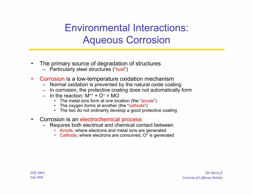
Environmental Interactions: Aqueous Corrosion
• The primary source of degradation of structures – Particularly steel structures (“rust”)
• Corrosion is a low-temperature oxidation mechanism – Normal oxidation is prevented by the natural oxide coating – In corrosion, the protective coating does not automatically form – In the reaction: M++ + O= = MO
• The metal ions form at one location (the “anode”) • The oxygen forms at another (the “cathode”) • The two do not ordinarily develop a good protective coating
• Corrosion is an electrochemical process – Requires both electrical and chemical contact between
• Anode, where electrons and metal ions are generated • Cathode, where electrons are consumed, O= is generated
J.W. Morris, Jr. University of California, Berkeley
MSE 200A Fall, 2008
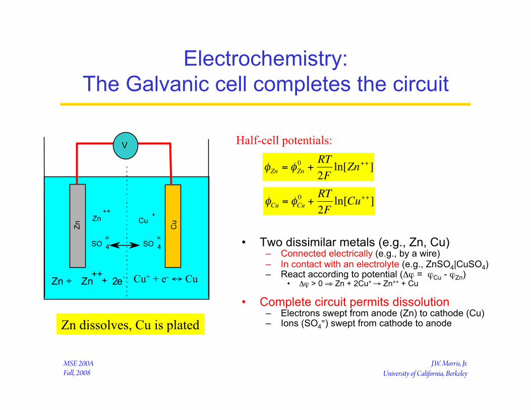
Electrochemistry: The Galvanic cell completes the circuit
• Two dissimilar metals (e.g., Zn, Cu) – Connected electrically (e.g., by a wire) – In contact with an electrolyte (e.g., ZnSO4|CuSO4) – React according to potential (Δϕ = ϕCu - ϕZn)
• Δϕ > 0 ⇒ Zn + 2Cu+ → Zn++ + Cu
• Complete circuit permits dissolution – Electrons swept from anode (Zn) to cathode (Cu) – Ions (SO4
=) swept from cathode to anode
Half-cell potentials:
€
φZn = φZn0 +
RT2Fln[Zn++]
€
φCu = φCu0 +
RT2Fln[Cu++]
Zn
Cu Zn ++
Cu +
SO 4 =
SO 4 =
V
e - Zn ÷ Zn ++ + 2 Cu+ + e- ↔ Cu
Zn dissolves, Cu is plated

J.W. Morris, Jr. University of California, Berkeley
MSE 200A Fall, 2008
The Galvanic Series in Seawater
Increasingly anodic ‘ TinMagnesium NickelMagnesium alloys Brasses (Cu-Zn)Zinc CopperAluminum Bronzes (Cu-Sn)Al-Cu alloys Silver soldersMild steel Nickel (passive)Wrought iron Monel (70Ni-30Cu)Cast iron Titanium18Cr-8Ni stainless steel (non-passivated) 18Cr-8Ni stainless steel (passive)50Pb-50Sn solder GoldLead Increasing cathodic ’
• The more anodic material in the couple is corroded
• Note: alloys are (generally) cathodic to pure metals – Free energy decreases on alloying

J.W. Morris, Jr. University of California, Berkeley
MSE 200A Fall, 2008
Concentration Cell
• Let a cell have Zn at both electrodes
• If the Zn concentration is different – A potential difference is developed – The side with the lower Zn concentration has lower potential – Lower Zn is the anode; is corroded
€
φZn = φZn0 +
RT2Fln[Zn++]
Zn ⇔ Zn++ + 2e-
€
Δφ =RT2Fln
Zn++[ ]1Zn++[ ]2

J.W. Morris, Jr. University of California, Berkeley
MSE 200A Fall, 2008
• Anode reactions: – Fe → Fe++ + 2e-
• Cathode reactions: – Normal cathode reaction:
2e- + 1/2O2 + H2O → 2(OH)-
– Acidic solution: 2e- + 2H+ → H2
– Strong potential: 2e- + H2O → 1/2H2 + (OH)-
• Oxidation reaction: – Fe++ + 2(OH)- → FeO + H2O – Note FeO may not coat surface
Cathode Reactions in Fe Corrosion
V
Fe Fe
H2O
OH- OH-
Fe++
Fe++

J.W. Morris, Jr. University of California, Berkeley
MSE 200A Fall, 2008
Galvanic Couples
• Dissimilar metal contact – Any two dissimilar conductors constitute a galvanic couple
• Microstructural heterogeneities – More stable grain or region (lowest free energy) is the cathode – High free energy due to:
• Mechanical deformation (defects) • Chemical heterogeneity • Phase or microstructural difference

J.W. Morris, Jr. University of California, Berkeley
MSE 200A Fall, 2008
Oxygen Concentration Cells
• Water immersion – [O2] decreases with depth – Cathode at surface – Anode at depth ⇒ Corrosion below water line
• Pitting corrosion – O2 denuded at base of pit – O2 replenished at surface – Anode at pit base ⇒ Corrosion deepens pit
€
φ =ϕ º+ RTnFln
O2[ ]1/ 2
OH−[ ]2
2e- + 1/2O2 + H2O ↔ 2OH- Cathode:

J.W. Morris, Jr. University of California, Berkeley
MSE 200A Fall, 2008
Crevice Corrosion
• Oxygen concentration cells develop at crevices – Rapid “crevice corrosion”
• Attacks rivets, screw heads, etc .
€
φ =ϕ º+ RTnFln
O2[ ]1/ 2
OH−[ ]2
2e- + 1/2O2 + H2O ↔ 2OH- Cathode:
J.W. Morris, Jr. University of California, Berkeley
MSE 200A Fall, 2008
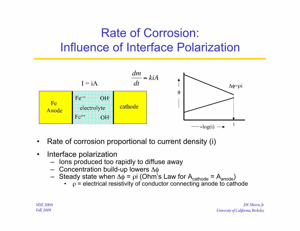
Rate of Corrosion: Influence of Interface Polarization
• Rate of corrosion proportional to current density (i)
• Interface polarization – Ions produced too rapidly to diffuse away – Concentration build-up lowers Δφ – Steady state when Δφ = ρi (Ohm’s Law for Acathode = Aanode)
• ρ = electrical resistivity of conductor connecting anode to cathode
φ
log(i) i
Δφ=ρi
€
dmdt
= kiAI = iA
-
J.W. Morris, Jr. University of California, Berkeley
MSE 200A Fall, 2008
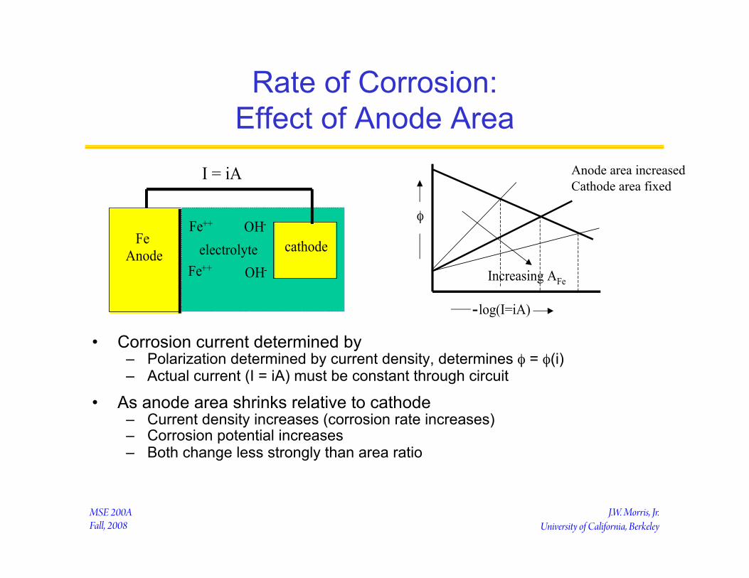
Rate of Corrosion: Effect of Anode Area
• Corrosion current determined by – Polarization determined by current density, determines φ = φ(i) – Actual current (I = iA) must be constant through circuit
• As anode area shrinks relative to cathode – Current density increases (corrosion rate increases) – Corrosion potential increases – Both change less strongly than area ratio
FeAnode electrolyte
Fe++
Fe++ OH-
OH-
cathode
I = iA
φ
log(I=iA)
Increasing AFe
Anode area increased Cathode area fixed
-

J.W. Morris, Jr. University of California, Berkeley
MSE 200A Fall, 2008
Protection Against Corrosion
• Break the circuit – Break electrical contact between metals – Break chemical contact with electrolyte
• Provide an alternate circuit – “cathodic protection”

J.W. Morris, Jr. University of California, Berkeley
MSE 200A Fall, 2008
Corrosion Protection: Breaking the Circuit
• Isolate anode from cathode – Insert insulator at dissimilar metal surface – Fe||Cu piping into a home – Teflon “sleeves” for rivets on aircraft
• Isolate metal from electrolyte by impermeable “paint” – Can paint either or both, but should paint cathode – Pin-hole break in anode risks catastrophic pitting corrosion – “Passivation”: material paints itself with oxide, like Al, Cr, stainless

J.W. Morris, Jr. University of California, Berkeley
MSE 200A Fall, 2008
Cathodic Protection
• Make the material the cathode
• Add a more anodic metal – “Sacrificial anode” – Must be in circuit
• Impose a reverse voltage – Reverse the sign of Δφ
FeMg
cathode
V
Fe
cathode

J.W. Morris, Jr. University of California, Berkeley
MSE 200A Fall, 2008
Galvanizing
• Protect metal by coating with an anodic material – Coating protects metal like paint – If coating is penetrated, cathodic protection kicks in – Automotive protection: paint plus galvanizing (Zn||Fe) – Aircraft protection: “alcladding” Al||Al alloy
• Do not coat with cathodic layer
Zn
Fe
J.W. Morris, Jr. University of California, Berkeley
MSE 200A Fall, 2008
Interfaces
• The engineering importance of surfaces – Wetting
• Frying pans and car waxes • Detergents • Lubricants
– Bonding • Glues • Solders
– Catalysis • Adsorption
– Capillarity • Tree sap and blood vessels
• The thermodynamics of surfaces – Surface tension – Wetting criteria

J.W. Morris, Jr. University of California, Berkeley
MSE 200A Fall, 2008
Interfaces and Wetting
• Conditions of equilibrium - open system – T, V (or A), {µ} fixed for interface
⇒ Ω(T,V,{µ}) = min = E - TS + ΣµkNk = - PV
• Assign excess quantities to surface
• ΩS(T,A,{µ}) = Ω - (Ωα + Ωβ )
transition shell dividing surface
€
ΩS =σA =min. (shape)
€
ΩS =σ =min. (state)
α
β
J.W. Morris, Jr. University of California, Berkeley
MSE 200A Fall, 2008
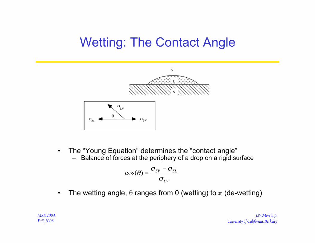
Wetting: The Contact Angle
• The “Young Equation” determines the “contact angle” – Balance of forces at the periphery of a drop on a rigid surface
• The wetting angle, θ ranges from 0 (wetting) to π (de-wetting)
€
cos(θ) =σ SV −σ SL
σ LV

J.W. Morris, Jr. University of California, Berkeley
MSE 200A Fall, 2008
Film Formation (Spreading)
• Spreading: LV+SL interfaces have lower energy than SV – Want for painting, coating, soldering, etc.
• To promote spreading – Raise σSV: e.g., clean the interface
• Flux in soldering removes oxides from surface – Lower σSL: e.g., include reactive species in L
• Sn in solder forms intermetallic compounds with Cu, Ni or Au – Lower σLV: e.g., add surfactant (species that adsorbs at LV interface)
• Flux in solder coats surface, lowers σLV
S
L V
€
σ SL +σ LV ≤σ SV
J.W. Morris, Jr. University of California, Berkeley
MSE 200A Fall, 2008
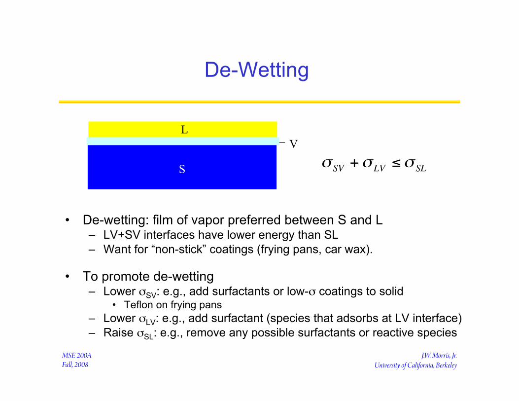
De-Wetting
• De-wetting: film of vapor preferred between S and L – LV+SV interfaces have lower energy than SL – Want for “non-stick” coatings (frying pans, car wax).
• To promote de-wetting – Lower σSV: e.g., add surfactants or low-σ coatings to solid
• Teflon on frying pans – Lower σLV: e.g., add surfactant (species that adsorbs at LV interface) – Raise σSL: e.g., remove any possible surfactants or reactive species
€
σ SV +σ LV ≤σ SLS
L V