LECTURE NOTES ON MECHATRONICS Note on Mechatronics-ilove… · Lecture Notes Mechatronics (M.Tech,...
81
Lecture Notes Mechatronics (M.Tech, Design Dynamics) 1 | Page LECTURE NOTES ON MECHATRONICS PREPARED BY Dr PRAMOD KUMAR PARIDA ASSISTANT PROFESSOR DEPARTMENT OF MECHANICAL ENGINEERING COLLEGE OF ENGINEERING & TECHNOLOGY (BPUT) BHUBANRSWAR
Transcript of LECTURE NOTES ON MECHATRONICS Note on Mechatronics-ilove… · Lecture Notes Mechatronics (M.Tech,...

Lecture Notes Mechatronics (M.Tech, Design Dynamics)
1 | P a g e
LECTURE NOTES ON
MECHATRONICS
PREPARED BY
Dr PRAMOD KUMAR PARIDA ASSISTANT PROFESSOR
DEPARTMENT OF MECHANICAL ENGINEERING
COLLEGE OF ENGINEERING & TECHNOLOGY (BPUT)
BHUBANRSWAR
Lecture Notes Mechatronics (M.Tech, Design Dynamics)
2 | P a g e
SYLLABUS
MECHATRONICS (3-0-0)
Fundamental of Mechantronics: Definition and concepts of Mechatronics, Conventional system
vs. mechatronic system, Need and Role of Mechantronics in Design, Manufacturing and Factory Automation. Hardware components for Mechatronics Number system in Mechatronics, Binary Logic, Karnaugh Map Minimization,
Transducer signal conditioning and Devices for Data conversion programmable controllers. ; Sensors and Transducers: An introduction to sensors and Transducers, use of sensor and transducer for specific purpose in mechatronic. ;
Signals, systems and Actuating Devices: Introduction to signals, systems and control system, representation, linearization of nonlinear systems, time Delays, measures of system performance, types of actuating devices selection. ; Real time interfacing: Introduction, Element of a Data Acquisition and control system, overview of the I/O process. Installation of the I/O card and software. ;
Application of software in Mechatronics: Advance application in Mechantronics. Sensors for conditioning Monitoring, Mechatronic Control in Automated Manufacturing, Micro sensors in Mechatronics. Case studies and examples in Data Acquisition and control. Automated manufacturing etc.
Essential Reading:
1. C.W.De Silva, Mechatronics: An Integrated Approach, Publisher: CRC;

Lecture Notes Mechatronics (M.Tech, Design Dynamics)
3 | P a g e
Module-I What is “Mechatronics”?
Mechatronics is a concept of Japanese origin (1980’s) and can be
defined as the application of electronics and computer technology to control
the motions of mechanical systems.
Definition of Mechatronics
It is a multidisciplinary approach to product and manufacturing system
design (Figure). It involves application of electrical, mechanical, control and
computer engineering to develop products, processes and systems with
greater flexibility, ease in redesign and ability of reprogramming. It
concurrently includes all these disciplines.
Mechatronics: a multi-disciplinary approach
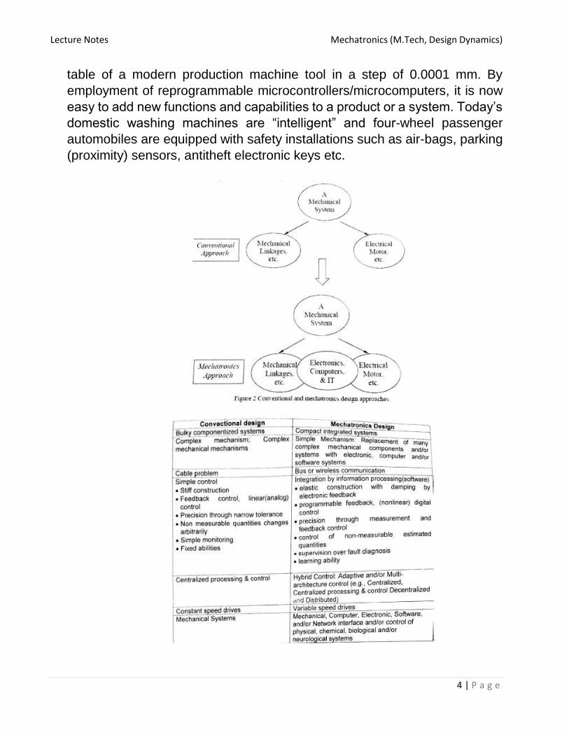
Mechatronics can also be termed as replacement of mechanics with
electronics or enhance mechanics with electronics. For example, in modern
automobiles, mechanical fuel injection systems are now replaced with
electronic fuel injection systems. This replacement made the automobiles
more efficient and less pollutant. With the help of microelectronics and
sensor technology, mechatronics systems are providing high levels of
precision and reliability. It is now possible to move (in x – y plane) the work
Lecture Notes Mechatronics (M.Tech, Design Dynamics)
4 | P a g e
table of a modern production machine tool in a step of 0.0001 mm. By
employment of reprogrammable microcontrollers/microcomputers, it is now
easy to add new functions and capabilities to a product or a system. Today’s
domestic washing machines are “intelligent” and four-wheel passenger
automobiles are equipped with safety installations such as air-bags, parking
(proximity) sensors, antitheft electronic keys etc.
Lecture Notes Mechatronics (M.Tech, Design Dynamics)
5 | P a g e
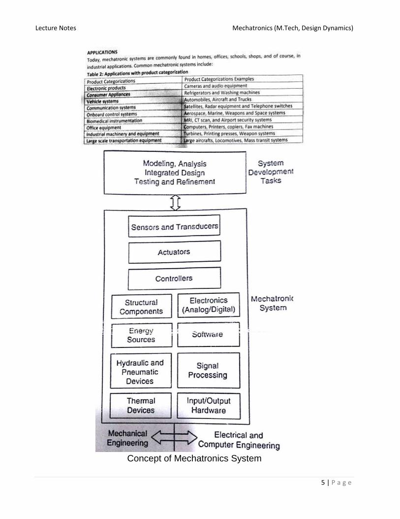
Concept of Mechatronics System

Lecture Notes Mechatronics (M.Tech, Design Dynamics)
6 | P a g e
Evolution Level of Mechatronics
1. Primary Level Mechatronics: This level incorporates I/O devices such as
sensors and actuators that integrates electrical signals with mechanical
action at the basic control levels.
Examples: Electrically controlled fluid valves and relays
2. Secondary Level Mechantronics: This level integrates microelectronics
into electrically controlled devices.
Examples: Cassette players
3. Third Level Mechatronics: This level incorporates advanced feedback
functions into control strategy thereby enhancing the quality in terms of
sophistication called smart system.
The control strategy includes microelectronics, microprocessor and
other ‘ Application Specific Integrated Circuits’ (ASIC)
Example: Control of Electrical motor used to activate industrial robots,
hard disk, CD drives and automatic washing machines.
4. Fourth Level Mechatronics: This level incorporates intelligent control in
mechatronics system. It introduces intelligence and fault detection and
isolation (FDI) capability systems.
Advantages and Disadvantages of Mechatronics system:

Lecture Notes Mechatronics (M.Tech, Design Dynamics)
7 | P a g e
Components of Mechatronics system:
The term mechatronics system (sometimes referred to as smart device)
encompasses a myriad of devices and systems. Increasingly,
microcontrollers are embedded in the elctromechanical devices, creating
much more flexibility and control possibilities in system design.
Components of a typical Mechatronics system
Actuators: produce motion or cause some action. Solenoids, voice calls, DC
motors, Stepper motor, servomotor, hydraulic, pneumatic.
Sensors: detect the state of the system parameters, inputs and outputs. Switches,
potentiometer, photoelctrics, digital encoder, strain gauge, thermocouple,
accelerometer etc.

Lecture Notes Mechatronics (M.Tech, Design Dynamics)
8 | P a g e
Input/output Signal conditioning and interfacing: provide connection between
the control system circuits and the input/output devices. Discrete circuits,
amplifiers, filters, A/D, D/A, power transistor etc.
Digital devices: controls the system. Logic circuits, micro controller, SBC, PLC
etc
Graphic Display: provide visual feed back to users. LEDs, Digital Displays, LCD,
CRT
Importance of Mechatronics in automation:
Operations involved in design and manufacturing of a product
Today’s customers are demanding more variety and higher levels of flexibility
in the products. Due to these demands and competition in the market,
manufacturers are thriving to launch new/modified products to survive. It is
reducing the product life as well as lead-time to manufacture a product. It is
therefore essential to automate the manufacturing and assembly operations
of a product. There are various activities involved in the product
manufacturing process. These are shown in figure 1.1.3. These activities can
be classified into two groups viz. design and manufacturing activities.

Lecture Notes Mechatronics (M.Tech, Design Dynamics)
9 | P a g e
Mechatronics concurrently employs the disciplines of mechanical, electrical,
control and computer engineering at the stage of design itself. Mechanical
discipline is employed in terms of various machines and mechanisms, where
as electrical engineering as various electric prime movers viz. AC/DC, servo
motors and other systems is used. Control engineering helps in the
development of various electronics-based control systems to enhance or
replace the mechanics of the mechanical systems. Computers are widely
used to write various softwares to control the control systems; product design
and development activities; materials and manufacturing resource planning,
record keeping, market survey, and other sales related activities.
Using computer aided design (CAD) / computer aided analysis (CAE) tools,
three-dimensional models of products can easily be developed. These
models can then be analyzed and can be simulated to study their
performances using numerical tools. These numerical tools are being
continuously updated or enriched with the real-life performances of the
similar kind of products. These exercises provide an approximate idea about
performance of the product/system to the design team at the early stage of
the product development. Based on the simulation studies, the designs can
be modified to achieve better performances. During the conventional design-
manufacturing process, the design assessment is generally carried out after
the production of first lot of the products. This consumes a lot of time, which
leads to longer (in months/years) product development lead-time. Use of
CAD–CAE tools saves significant time in comparison with that required in
the conventional sequential design process.
CAD-CAE generated final designs are then sent to the production and
process planning section. Mechatronics based systems such as computer
aided manufacturing (CAM): automatic process planning, automatic part
programming, manufacturing resource planning, etc. uses the design data
provided by the design team. Based these inputs, various activities will then
be planned to achieve the manufacturing targets in terms of quality and
quantity with in a stipulated time frame.
Mechatronics based automated systems such as automatic inspection and
quality assurance, automatic packaging, record making, and automatic
dispatch help to expedite the entire manufacturing operation. These systems
certainly ensure a supply better quality, well packed and reliable products in
the market. Automation in the machine tools has reduced the human

Lecture Notes Mechatronics (M.Tech, Design Dynamics)
10 | P a g e
intervention in the machining operation and improved the process efficiency
and product quality. Therefore, it is important to study the principles of
mechatronics and to learn how to apply them in the automation of a
manufacturing system.
Digital Codes:
Logic Gates:

Lecture Notes Mechatronics (M.Tech, Design Dynamics)
11 | P a g e

Lecture Notes Mechatronics (M.Tech, Design Dynamics)
12 | P a g e

Lecture Notes Mechatronics (M.Tech, Design Dynamics)
13 | P a g e

Lecture Notes Mechatronics (M.Tech, Design Dynamics)
14 | P a g e
Module-II Sensors and Transducers: An introduction to sensors and Transducers, use of sensor and transducer for
specific purpose in mechatronics. Transducer signal conditioning and Devices for Data conversion
programmable controllers. ;
Sensors and transducers
Measurement is an important subsystem of a mechatronics system. Its main
function is to collect the information on system status and to feed it to the
micro-processor(s) for controlling the whole system.
Measurement system comprises of sensors, transducers and signal processing
devices. Today a wide variety of these elements and devices are available
in the market.
For a mechatronics system designer it is quite difficult to choose suitable
sensors/transducers for the desired application(s). It is therefore essential to
learn the principle of working of commonly used sensors/transducers.
Sensors in manufacturing are basically employed to automatically carry out the
production operations as well as process monitoring activities. Sensor
technology has the following important advantages in transforming a
conventional manufacturing unit into a modern one.
Sensors alarm the system operators about the failure of any of the sub
units of manufacturing system. It helps operators to reduce the
downtime of complete manufacturing system by carrying out the
preventative measures.
Reduces requirement of skilled and experienced labors.
Ultra-precision in product quality can be achieved.
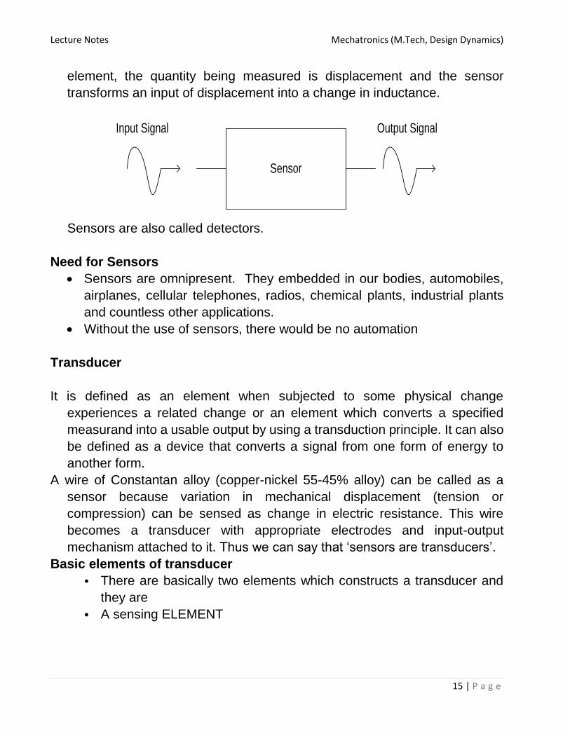
Sensor
It is defined as an element which produces signal relating to the quantity being
measured. According to the Instrument Society of America, sensor can be
defined as “A device which provides a usable output in response to a
specified measurand.” Here, the output is usually an ‘electrical quantity’ and
measurand is a ‘physical quantity, property or condition which is to be
measured’. Thus in the case of, say, a variable inductance displacement
Lecture Notes Mechatronics (M.Tech, Design Dynamics)
15 | P a g e
element, the quantity being measured is displacement and the sensor
transforms an input of displacement into a change in inductance.
Sensor
Input Signal Output Signal
Sensors are also called detectors.
Need for Sensors
Sensors are omnipresent. They embedded in our bodies, automobiles,
airplanes, cellular telephones, radios, chemical plants, industrial plants
and countless other applications.
Without the use of sensors, there would be no automation
Transducer
It is defined as an element when subjected to some physical change
experiences a related change or an element which converts a specified
measurand into a usable output by using a transduction principle. It can also
be defined as a device that converts a signal from one form of energy to
another form.
A wire of Constantan alloy (copper-nickel 55-45% alloy) can be called as a
sensor because variation in mechanical displacement (tension or
compression) can be sensed as change in electric resistance. This wire
becomes a transducer with appropriate electrodes and input-output
mechanism attached to it. Thus we can say that ‘sensors are transducers’.
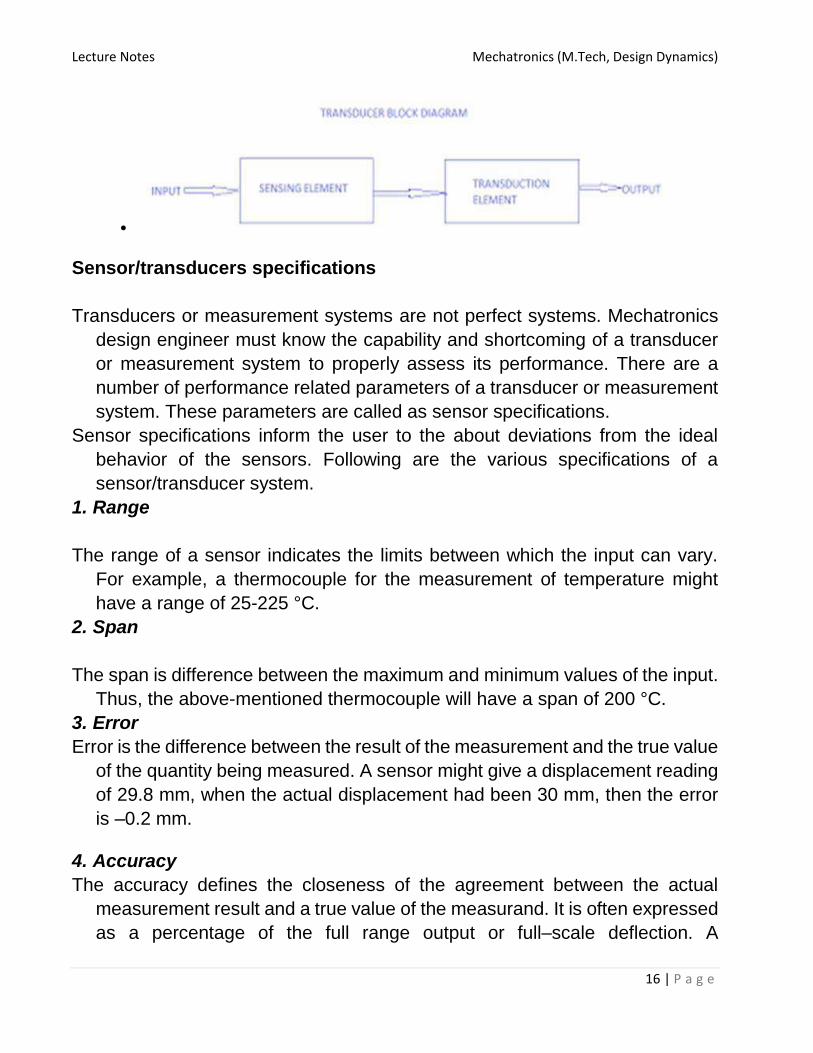
Basic elements of transducer
• There are basically two elements which constructs a transducer and
they are
• A sensing ELEMENT
Lecture Notes Mechatronics (M.Tech, Design Dynamics)
16 | P a g e
•
Sensor/transducers specifications
Transducers or measurement systems are not perfect systems. Mechatronics
design engineer must know the capability and shortcoming of a transducer
or measurement system to properly assess its performance. There are a
number of performance related parameters of a transducer or measurement
system. These parameters are called as sensor specifications.
Sensor specifications inform the user to the about deviations from the ideal
behavior of the sensors. Following are the various specifications of a
sensor/transducer system.
1. Range
The range of a sensor indicates the limits between which the input can vary.
For example, a thermocouple for the measurement of temperature might
have a range of 25-225 °C.
2. Span
The span is difference between the maximum and minimum values of the input.
Thus, the above-mentioned thermocouple will have a span of 200 °C.
3. Error
Error is the difference between the result of the measurement and the true value
of the quantity being measured. A sensor might give a displacement reading
of 29.8 mm, when the actual displacement had been 30 mm, then the error
is –0.2 mm.
4. Accuracy
The accuracy defines the closeness of the agreement between the actual
measurement result and a true value of the measurand. It is often expressed
as a percentage of the full range output or full–scale deflection. A
Lecture Notes Mechatronics (M.Tech, Design Dynamics)
17 | P a g e
piezoelectric transducer used to evaluate dynamic pressure phenomena
associated with explosions, pulsations, or dynamic pressure conditions in
motors, rocket engines, compressors, and other pressurized devices is
capable to detect pressures between 0.1 and 10,000 psig (0.7 KPa to 70
MPa). If it is specified with the accuracy of about ±1% full scale, then the
reading given can be expected to be within ± 0.7 MPa.
5. Sensitivity
Sensitivity of a sensor is defined as the ratio of change in output value of a
sensor to the per unit change in input value that causes the output change.
For example, a general purpose thermocouple may have a sensitivity of 41
μV/°C.
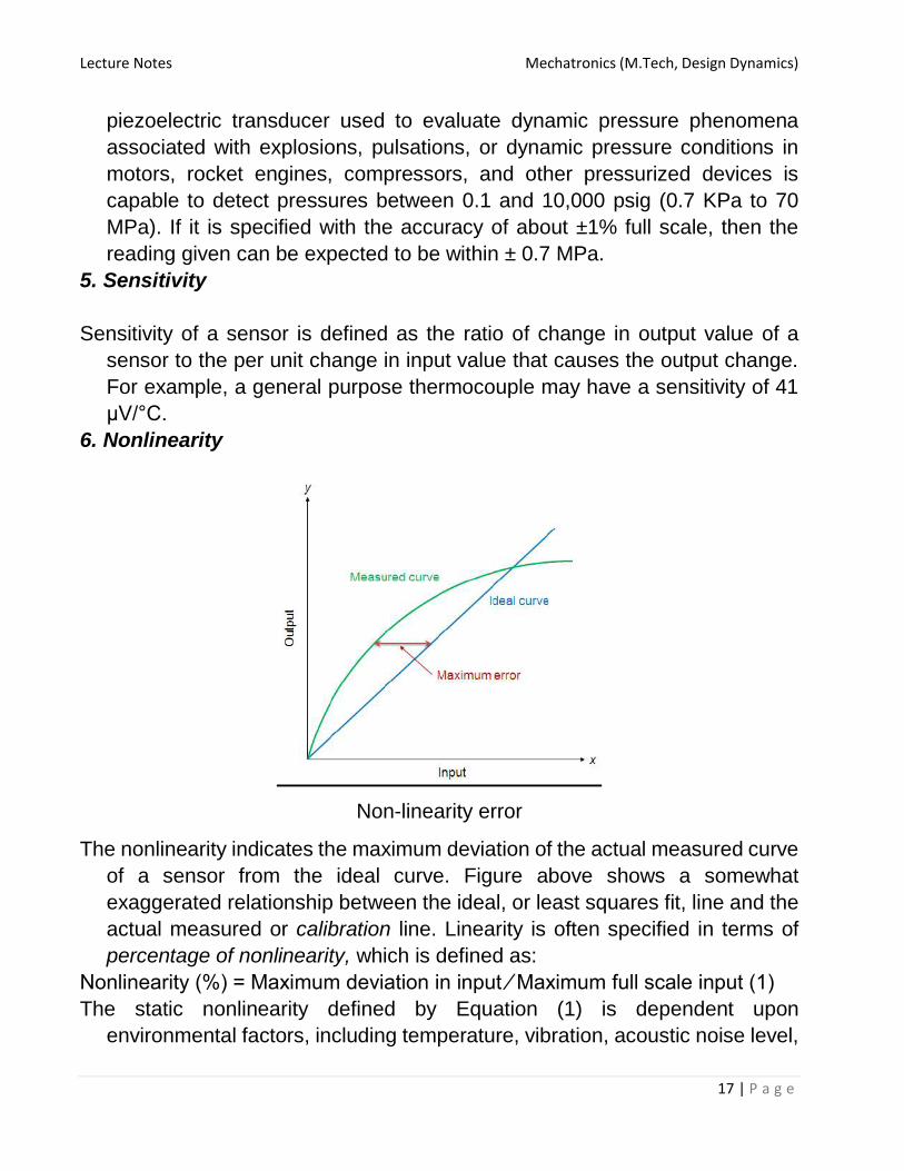
6. Nonlinearity
Non-linearity error
The nonlinearity indicates the maximum deviation of the actual measured curve
of a sensor from the ideal curve. Figure above shows a somewhat
exaggerated relationship between the ideal, or least squares fit, line and the
actual measured or calibration line. Linearity is often specified in terms of
percentage of nonlinearity, which is defined as:
Nonlinearity (%) = Maximum deviation in input ⁄ Maximum full scale input (1)
The static nonlinearity defined by Equation (1) is dependent upon
environmental factors, including temperature, vibration, acoustic noise level,

Lecture Notes Mechatronics (M.Tech, Design Dynamics)
18 | P a g e
and humidity. Therefore it is important to know under what conditions the
specification is valid.
7. Hysteresis
Hysteresis error curve
The hysteresis is an error of a sensor, which is defined as the maximum
difference in output at any measurement value within the sensor’s specified
range when approaching the point first with increasing and then with
decreasing the input parameter. Figure above shows the hysteresis error
might have occurred during measurement of temperature using a
thermocouple. The hysteresis error value is normally specified as a positive
or negative percentage of the specified input range.
8. Resolution
Resolution is the smallest detectable incremental change of input parameter
that can be detected in the output signal. Resolution can be expressed either
as a proportion of the full-scale reading or in absolute terms. For example, if
a LVDT sensor measures a displacement up to 20 mm and it provides an
output as a number between 1 and 100 then the resolution of the sensor
device is 0.2 mm.
9. Stability

Lecture Notes Mechatronics (M.Tech, Design Dynamics)
19 | P a g e
Stability is the ability of a sensor device to give same output when used to
measure a constant input over a period of time. The term ‘drift’ is used to
indicate the change in output that occurs over a period of time. It is expressed
as the percentage of full range output.
10.Dead band/time
The dead band or dead space of a transducer is the range of input values for
which there is no output. The dead time of a sensor device is the time
duration from the application of an input until the output begins to respond or
change.
11.Repeatability
It specifies the ability of a sensor to give same output for repeated applications
of same input value. It is usually expressed as a percentage of the full range
output:
Repeatability = (maximum – minimum values given) X 100 ⁄ full range (2)
12.Response time
Response time describes the speed of change in the output on a step-wise
change of the measurand. It is always specified with an indication of input
step and the output range for which the response time is defined.
Classification of sensors
Sensors can be classified into various groups according to the factors such as
measurand, application fields, conversion principle, energy domain of the
measurand and thermodynamic considerations. These general
classifications of sensors are well described in the references
Detail classification of sensors in view of their applications in manufacturing is
as follows.
A. Displacement, position and proximity sensors
• Potentiometer
• Strain-gauged element
• Capacitive element
• Differential transformers
• Eddy current proximity sensors
• Inductive proximity switch
Lecture Notes Mechatronics (M.Tech, Design Dynamics)
20 | P a g e
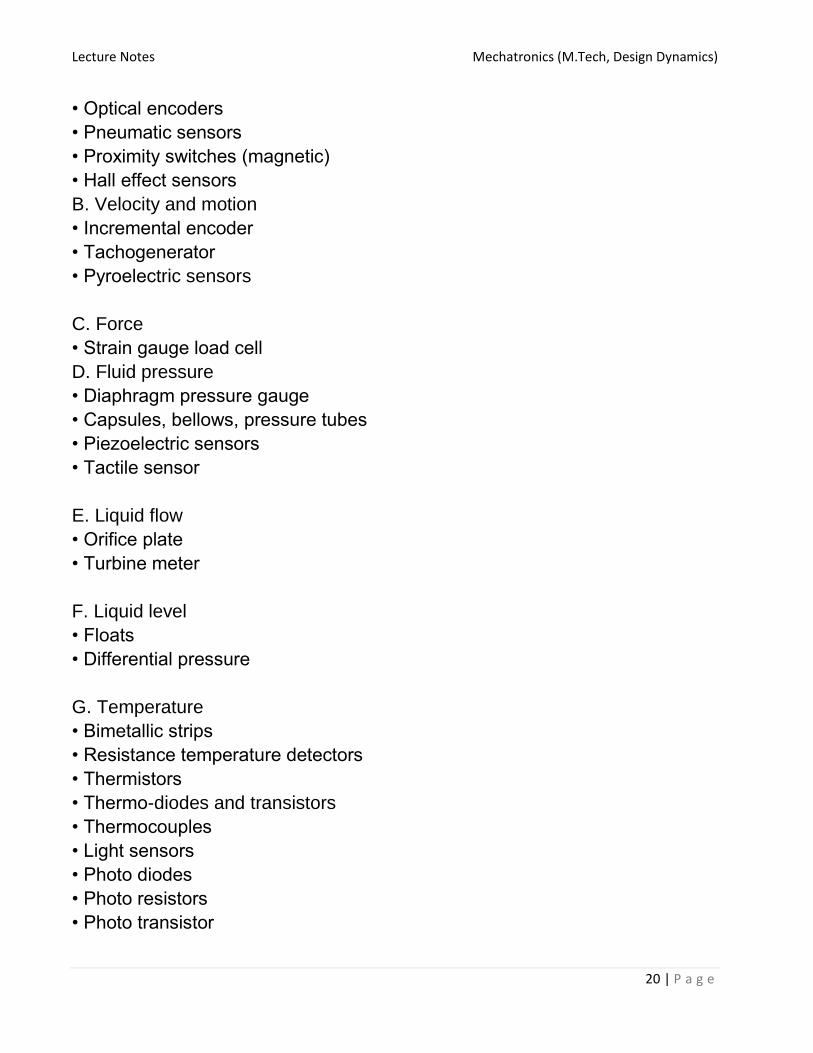
• Optical encoders
• Pneumatic sensors
• Proximity switches (magnetic)
• Hall effect sensors
B. Velocity and motion
• Incremental encoder
• Tachogenerator
• Pyroelectric sensors
C. Force
• Strain gauge load cell
D. Fluid pressure
• Diaphragm pressure gauge
• Capsules, bellows, pressure tubes
• Piezoelectric sensors
• Tactile sensor
E. Liquid flow
• Orifice plate
• Turbine meter
F. Liquid level
• Floats
• Differential pressure
G. Temperature
• Bimetallic strips
• Resistance temperature detectors
• Thermistors
• Thermo-diodes and transistors
• Thermocouples
• Light sensors
• Photo diodes
• Photo resistors
• Photo transistor

Lecture Notes Mechatronics (M.Tech, Design Dynamics)
21 | P a g e
Displacement and position sensors
Displacement sensors are basically used for the measurement of movement
of an object. Position sensors are employed to determine the position of an
object in relation to some reference point.
Proximity sensors are a type of position sensor and are used to trace when
an object has moved with in particular critical distance of a transducer.
Displacement sensors
1. Potentiometer Sensors
Schematic of a potentiometer sensor for measurement of linear
displacement
Figure above shows the construction of a rotary type potentiometer sensor
employed to measure the linear displacement. The potentiometer can be of
linear or angular type. It works on the principle of conversion of mechanical
displacement into an electrical signal. The sensor has a resistive element
and a sliding contact (wiper). The slider moves along this conductive body,
acting as a movable electric contact.
The object of whose displacement is to be measured is connected to the
slider by using
• a rotating shaft (for angular displacement)
• a moving rod (for linear displacement)

Lecture Notes Mechatronics (M.Tech, Design Dynamics)
22 | P a g e
• a cable that is kept stretched during operation
The resistive element is a wire wound track or conductive plastic. The track
comprises of large number of closely packed turns of a resistive wire.
Conductive plastic is made up of plastic resin embedded with the carbon
powder. Wire wound track has a resolution of the order of ± 0.01 % while the
conductive plastic may have the resolution of about 0.1 μm.
During the sensing operation, a voltage Vs is applied across the resistive
element. A voltage divider circuit is formed when slider comes into contact
with the wire. The output voltage (VA) is measured as shown in the figure
below. The output voltage is proportional to the displacement of the slider
over the wire. Then the output parameter displacement is calibrated against
the output voltage VA.
Potentiometer: electric circuit
Applications of potentiometer
These sensors are primarily used in the control systems with a feedback loop
to ensure that the moving member or component reaches its commanded
position.
These are typically used on machine-tool controls, elevators, liquid-level
assemblies, forklift trucks, automobile throttle controls. In manufacturing,
these are used in control of injection molding machines, woodworking

Lecture Notes Mechatronics (M.Tech, Design Dynamics)
23 | P a g e
machinery, printing, spraying, robotics, etc. These are also used in
computer-controlled monitoring of sports equipment.
Strain Gauges
The strain in an element is a ratio of change in length in the direction of
applied load to the original length of an element. The strain changes the
resistance R of the element. Therefore, we can say,
ΔR/R α ε;
ΔR/R = G ε (2.2.5)
where G is the constant of proportionality and is called as gauge factor.
In general, the value of G is considered in between 2 to 4 and the
resistances are taken of the order of 100 Ω.
A pattern of resistive foils

Lecture Notes Mechatronics (M.Tech, Design Dynamics)
24 | P a g e
Whetstone’s bridge
Resistance strain gauge follows the principle of change in resistance as per
the equation 2.2.5. It comprises of a pattern of resistive foil arranged as
shown in Figure 2.2.3. These foils are made of Constantan alloy (copper-
nickel 55-45% alloy) and are bonded to a backing material plastic
(ployimide), epoxy or glass fiber reinforced epoxy. The strain gauges are
secured to the workpiece by using epoxy or Cyanoacrylate cement Eastman
910 SL. As the workpiece undergoes change in its shape due to external
loading, the resistance of strain gauge element changes. This change in
resistance can be detected by a using a Wheatstone’s resistance bridge as
shown in Figure 2.2.4. In the balanced bridge we can have a relation,
R2/ R1 = Rx / R3
where Rx is resistance of strain gauge element, R2 is balancing/adjustable
resistor, R1 and R3 are known constant value resistors. The measured
deformation or displacement by the stain gauge is calibrated against change
Lecture Notes Mechatronics (M.Tech, Design Dynamics)
25 | P a g e
in resistance of adjustable resistor R2 which makes the voltage across nodes
A and B equal to zero.
Applications of strain gauges
Strain gauges are widely used in experimental stress analysis and diagnosis
on machines and failure analysis. They are basically used for multi-axial
stress fatigue testing, proof testing, residual stress and vibration
measurement, torque measurement, bending and deflection measurement,
compression and tension measurement and strain measurement.
Strain gauges are primarily used as sensors for machine tools and safety in
automotives. In particular, they are employed for force measurement in
machine tools, hydraulic or pneumatic press and as impact sensors in
aerospace vehicles.
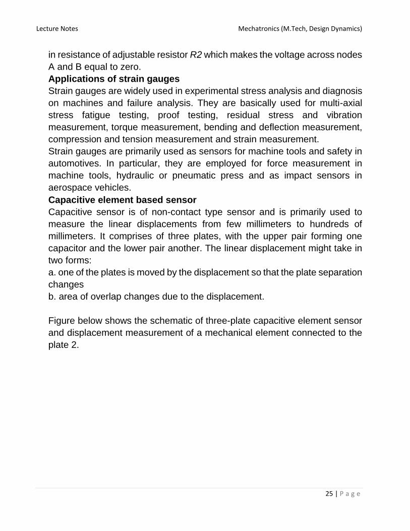
Capacitive element based sensor
Capacitive sensor is of non-contact type sensor and is primarily used to
measure the linear displacements from few millimeters to hundreds of
millimeters. It comprises of three plates, with the upper pair forming one
capacitor and the lower pair another. The linear displacement might take in
two forms:
a. one of the plates is moved by the displacement so that the plate separation
changes
b. area of overlap changes due to the displacement.
Figure below shows the schematic of three-plate capacitive element sensor
and displacement measurement of a mechanical element connected to the
plate 2.
Lecture Notes Mechatronics (M.Tech, Design Dynamics)
26 | P a g e
Displacement measurement using capacitive element sensor
The capacitance C of a parallel plate capacitor is given by, C = εr εo A / d
where εr is the relative permittivity of the dielectric between the plates, εo
permittivity of free space, A area of overlap between two plates and d the
plate separation.
As the central plate moves near to top plate or bottom one due to the
movement of the element /workpiece of which displacement is to be
measured, separation in between the plate changes. This can be given as,
C1 = (εr εo A) / (d + x)
C2 = (εr εo A) / (d – x)
When C1 and C2 are connected to a Wheatsone’s bridge, then the resulting
out-of-balance voltage would be in proportional to displacement x.
Capacitive elements can also be used as proximity sensor. The approach of
the object towards the sensor plate is used for induction of change in plate
separation. This changes the capacitance which is used to detect the object.
Applications of capacitive element sensors

Lecture Notes Mechatronics (M.Tech, Design Dynamics)
27 | P a g e
• Feed hopper level monitoring
• Small vessel pump control
• Grease level monitoring
• Level control of liquids
• Metrology applications o to measure shape errors in the part being
produced
o to analyze and optimize the rotation of spindles in various machine tools
such as surface grinders, lathes, milling machines, and air bearing spindles
by measuring errors in the machine tools themselves
• Assembly line testing o to test assembled parts for uniformity, thickness or
other design features
o to detect the presence or absence of a certain component, such as glue
etc.
Linear variable differential transformer (LVDT)
Construction of a LVDT sensor
Linear variable differential transformer (LVDT) is a primary transducer used
for measurement of linear displacement with an input range of about ± 2 to
± 400 mm in general. It has non-linearity error ± 0.25% of full range. Figure
2.2.6 shows the construction of a LVDT sensor. It has three coils
symmetrically spaced along an insulated tube. The central coil is primary coil
and the other two are secondary coils. Secondary coils are connected in
series in such a way that their outputs oppose each other. A magnetic core
attached to the element of which displacement is to be monitored is placed
inside the insulated tube.

Lecture Notes Mechatronics (M.Tech, Design Dynamics)
28 | P a g e
Working of LVDT sensor
Due to an alternating voltage input to the primary coil, alternating electro-
magnetic forces (emfs) are generated in secondary coils. When the magnetic
core is centrally placed with its half portion in each of the secondary coil
regions then the resultant voltage is zero. If the core is displaced from the
central position as shown in Figure 2.2.7, say, more in secondary coil 1 than
in coil 2, then more emf is generated in one coil i.e. coil 1 than the other, and
there is a resultant voltage from the coils. If the magnetic core is further
displaced, then the value of resultant voltage increases in proportion with the
displacement. With the help of signal processing devices such as low pass
filters and demodulators, precise displacement can be measured by using
LVDT sensors.
LVDT exhibits good repeatability and reproducibility. It is generally used as
an absolute position sensor. Since there is no contact or sliding between the
constituent elements of the sensor, it is highly reliable. These sensors are
completely sealed and are widely used in Servomechanisms, automated
measurement in machine tools.
A rotary variable differential transformer (RVDT) can be used for the
measurement of rotation. Readers are suggested to prepare a report on
principle of working and construction of RVDT sensor.
Applications of LVDT sensors
• Measurement of spool position in a wide range of servo valve applications
• To provide displacement feedback for hydraulic cylinders
• To control weight and thickness of medicinal products viz. tablets or pills

Lecture Notes Mechatronics (M.Tech, Design Dynamics)
29 | P a g e
• For automatic inspection of final dimensions of products being packed for
dispatch
• To measure distance between the approaching metals during Friction
welding process
• To continuously monitor fluid level as part of leak detection system
• To detect the number of currency bills dispensed by an ATM
Displacement, position and proximity sensors
Eddy current proximity sensors
Schematic of Inductive Proximity Sensor
Eddy current proximity sensors are used to detect non-magnetic but
conductive materials. They comprise of a coil, an oscillator, a detector and a
triggering circuit. Figure 2.3.1 shows the construction of eddy current
proximity switch. When an alternating current is passed thru this coil, an
alternative magnetic field is generated. If a metal object comes in the close
proximity of the coil, then eddy currents are induced in the object due to the
magnetic field. These eddy currents create their own magnetic field which
distorts the magnetic field responsible for their generation. As a result,
impedance of the coil changes and so the amplitude of alternating current.
This can be used to trigger a switch at some pre-determined level of change
in current.
Eddy current sensors are relatively inexpensive, available in small in size,
highly reliable and have high sensitivity for small displacements.
Applications of eddy current proximity sensors
• Automation requiring precise location
• Machine tool monitoring

Lecture Notes Mechatronics (M.Tech, Design Dynamics)
30 | P a g e
• Final assembly of precision equipment such as disk drives
• Measuring the dynamics of a continuously moving target, such as a
vibrating element,
• Drive shaft monitoring
• Vibration measurements
Pneumatic Sensors
Working of Pneumatic Sensors
Pneumatic sensors are used to measure the displacement as well as to
sense the proximity of an object close to it. The displacement and proximity
are transformed into change in air pressure. Figure 2.3.4 shows a schematic
of construction and working of such a sensor. It comprises of three ports.
Low pressure air is allowed to escape through port A. In the absence of any
obstacle / object, this low pressure air escapes and in doing so, reduces the
pressure in the port B. However when an object obstructs the low pressure
air (Port A), there is rise in pressure in output port B. This rise in pressure is
calibrated to measure the displacement or to trigger a switch. These sensors
are used in robotics, pneumatics and for tooling in CNC machine tools.
Lecture Notes Mechatronics (M.Tech, Design Dynamics)
31 | P a g e
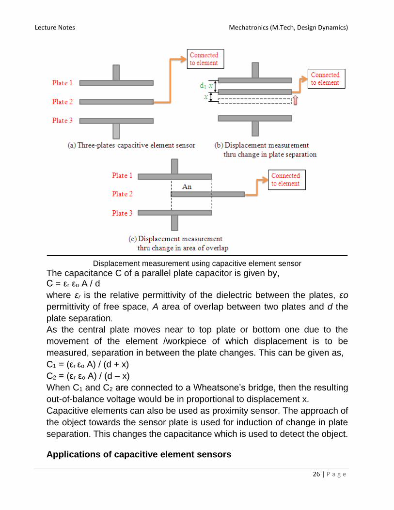
Proximity Switches
Figure above shows a number of configurations of contact-type proximity
switch being used in manufacturing automation. These are small electrical
switches which require physical contact and a small operating force to close
the contacts. They are basically employed on conveyor systems to detect
the presence of an item on the conveyor belt.
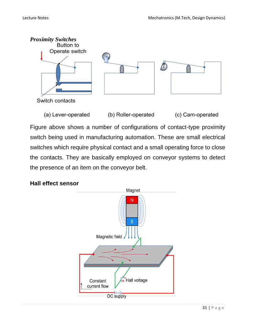
Hall effect sensor
Lecture Notes Mechatronics (M.Tech, Design Dynamics)
32 | P a g e
Principle of working of Hall effect sensor
Figure above shows the principle of working of Hall effect sensor. Hall effect
sensors work on the principle that when a beam of charge particles passes
through a magnetic field, forces act on the particles and the current beam is
deflected from its straight line path. Thus one side of the disc will become
negatively charged and the other side will be of positive charge. This charge
separation generates a potential difference which is the measure of distance
of magnetic field from the disc carrying current.
The typical application of Hall effect sensor is the measurement of fluid level
in a container. The container comprises of a float with a permanent magnet
attached at its top. An electric circuit with a current carrying disc is mounted
in the casing. When the fluid level increases, the magnet will come close to
the disc and a potential difference generates. This voltage triggers a switch
to stop the fluid to come inside the container.
These sensors are used for the measurement of displacement and the
detection of position of an object. Hall effect sensors need necessary signal
conditioning circuitry. They can be operated at 100 kHz. Their non-contact
nature of operation, good immunity to environment contaminants and ability
to sustain in severe conditions make them quite popular in industrial
automation.
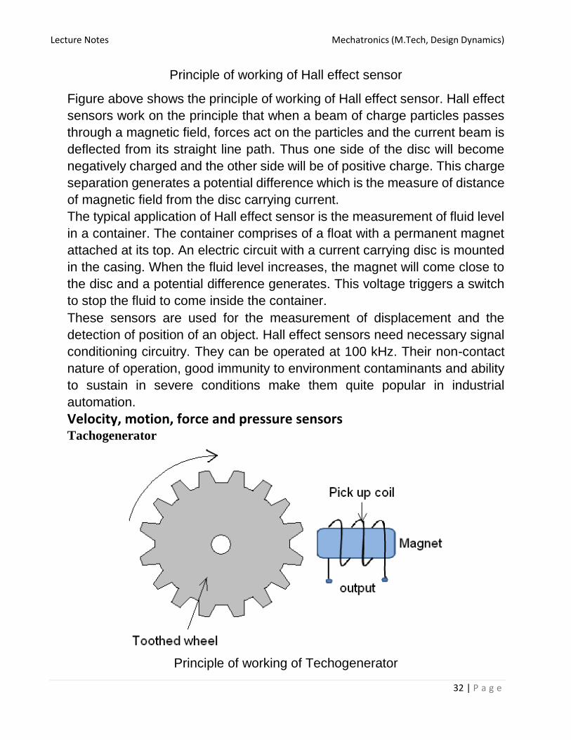
Velocity, motion, force and pressure sensors Tachogenerator
Principle of working of Techogenerator

Lecture Notes Mechatronics (M.Tech, Design Dynamics)
33 | P a g e
Tachogenerator works on the principle of variable reluctance. It consists of
an assembly of a toothed wheel and a magnetic circuit as shown in figure
2.4.1. Toothed wheel is mounted on the shaft or the element of which angular
motion is to be measured. Magnetic circuit comprising of a coil wound on a
ferromagnetic material core. As the wheel rotates, the air gap between wheel
tooth and magnetic core changes which results in cyclic change in flux linked
with the coil. The alternating emf generated is the measure of angular
motion. A pulse shaping signal conditioner is used to transform the output
into a number of pulses which can be counted by a counter.
Pyroelectric sensors
Principle of pyroelectricity
These sensors work on the principle of pyroelectricity, which states that a
crystal material such as Lithium tantalite generates charge in response to
heat flow. In presence of an electric field, when such a crystal material heats
up, its electrical dipoles line up as shown in figure 2.4.3. This is called as
polarization. On cooling, the material retains its polarization. In absence of
electric field, when this polarized material is subjected to infrared irradiation,
its polarization reduces. This phenomenon is the measure of detection of
movement of an object.

Lecture Notes Mechatronics (M.Tech, Design Dynamics)
34 | P a g e
Construction and working a Pyroelectric sensor
Pyroelectric sensor comprises of a thick element of polarized material coated
with thin film electrodes on opposite faces as shown in figure 2.4.4. Initially
the electrodes are in electrical equilibrium with the polarized material. On
incident of infra red, the material heats up and reduces its polarization. This
leads to charge imbalance at the interface of crystal and electrodes. To
balance this disequilibrium, measurement circuit supplies the charge, which
is calibrated against the detection of an object or its movement. Applications of Pyroelectric sensors • Intrusion detector • Optothermal detector • Pollution detector • Position sensor • Solar cell studies • Engine analysis
Lecture Notes Mechatronics (M.Tech, Design Dynamics)
35 | P a g e
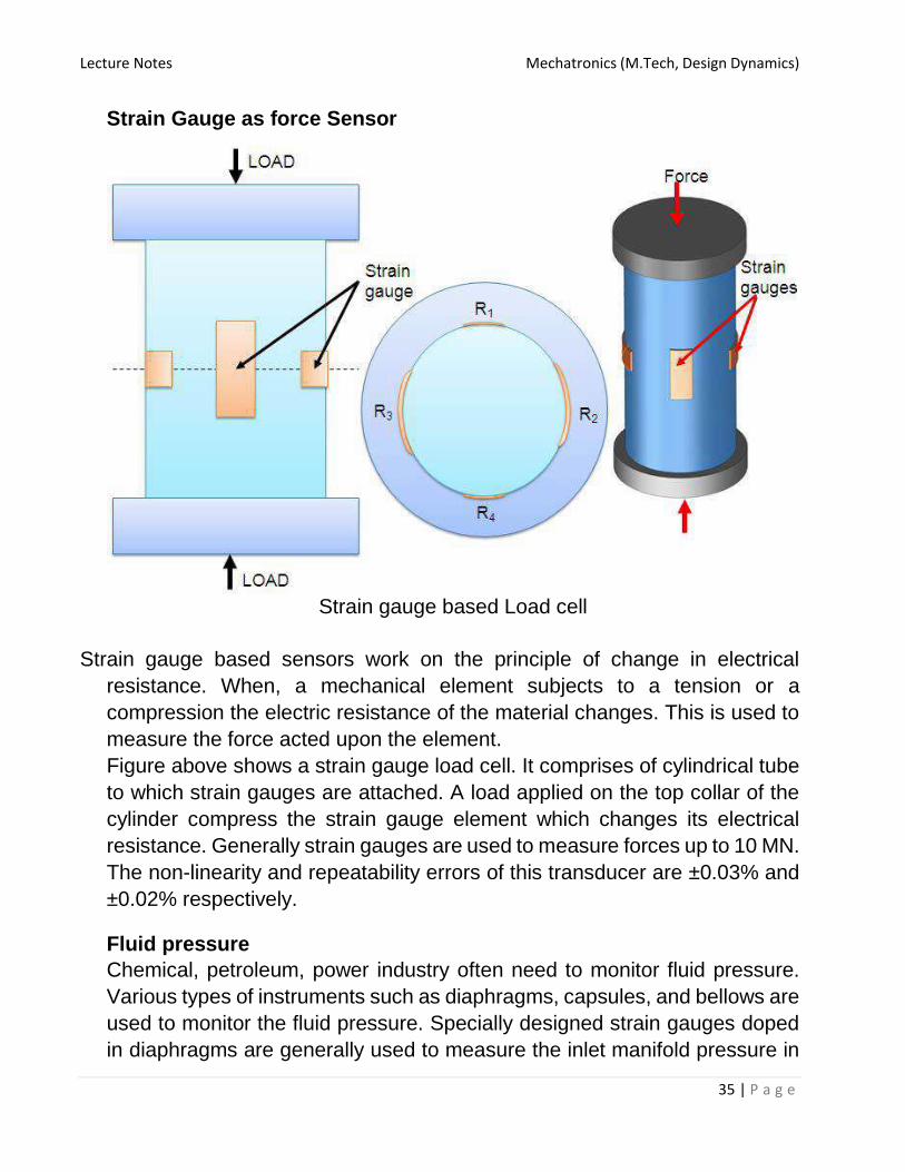
Strain Gauge as force Sensor
Strain gauge based Load cell
Strain gauge based sensors work on the principle of change in electrical
resistance. When, a mechanical element subjects to a tension or a
compression the electric resistance of the material changes. This is used to
measure the force acted upon the element.
Figure above shows a strain gauge load cell. It comprises of cylindrical tube
to which strain gauges are attached. A load applied on the top collar of the
cylinder compress the strain gauge element which changes its electrical
resistance. Generally strain gauges are used to measure forces up to 10 MN.
The non-linearity and repeatability errors of this transducer are ±0.03% and
±0.02% respectively.
Fluid pressure
Chemical, petroleum, power industry often need to monitor fluid pressure.
Various types of instruments such as diaphragms, capsules, and bellows are
used to monitor the fluid pressure. Specially designed strain gauges doped
in diaphragms are generally used to measure the inlet manifold pressure in

Lecture Notes Mechatronics (M.Tech, Design Dynamics)
36 | P a g e
applications such as automobiles. A typical arrangement of strain gauges on
a diaphragm is shown in figure 2.4.6. Application of pressurized fluid
displaces the diaphragm. This displacement is measured by the stain
gauges in terms of radial and/or lateral strains. These strain gauges are
connected to form the arms of a Wheatstone bridge.
A diaphragm

Lecture Notes Mechatronics (M.Tech, Design Dynamics)
37 | P a g e
Schematic of Capsule and Bellow
Bellow with a LVDT
Capsule is formed by combining two corrugated diaphragms. It has
enhanced sensitivity in comparison with that of diaphragms. Figure 2.4.7
shows a schematic of a Capsule and a Bellow. A stack of capsules is called
as ‘Bellows’. Bellows with a LVDT sensor measures the fluid pressure in
terms of change in resultant voltage across the secondary coils of LVDT.
Figure above shows a typical arrangement of the same.

Lecture Notes Mechatronics (M.Tech, Design Dynamics)
38 | P a g e
Tactile sensors
Schematic of a tactile sensor
In general, tactile sensors are used to sense the contact of fingertips of a
robot with an object. They are also used in manufacturing of ‘touch display’
screens of visual display units (VDUs) of CNC machine tools. Figure 2.4.9
shows the construction of piezo-electric polyvinylidene fluoride (PVDF)
based tactile sensor. It has two PVDF layers separated by a soft film which
transmits the vibrations. An alternating current is applied to lower PVDF layer
which generates vibrations due to reverse piezoelectric effect. These
vibrations are transmitted to the upper PVDF layer via soft film. These
vibrations cause alternating voltage across the upper PVDF layer. When
some pressure is applied on the upper PVDF layer the vibrations gets
affected and the output voltage changes. This triggers a switch or an action
in robots or touch displays.
Piezoelectric sensor
Lecture Notes Mechatronics (M.Tech, Design Dynamics)
39 | P a g e
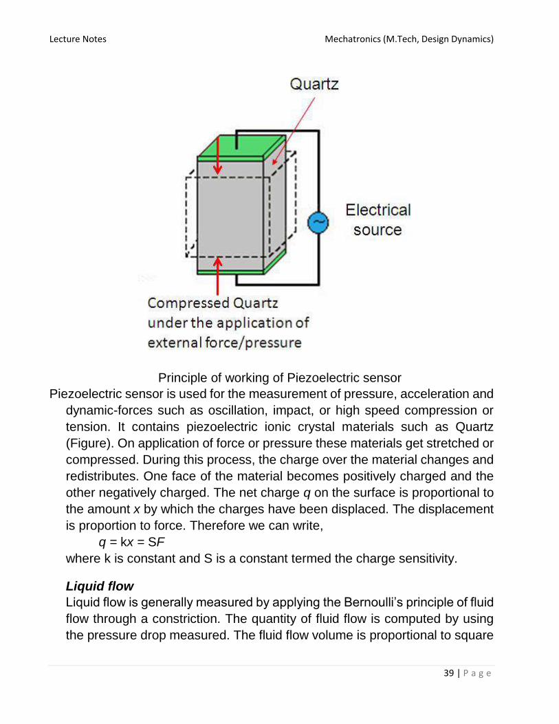
Principle of working of Piezoelectric sensor
Piezoelectric sensor is used for the measurement of pressure, acceleration and
dynamic-forces such as oscillation, impact, or high speed compression or
tension. It contains piezoelectric ionic crystal materials such as Quartz
(Figure). On application of force or pressure these materials get stretched or
compressed. During this process, the charge over the material changes and
redistributes. One face of the material becomes positively charged and the
other negatively charged. The net charge q on the surface is proportional to
the amount x by which the charges have been displaced. The displacement
is proportion to force. Therefore we can write,
q = kx = SF
where k is constant and S is a constant termed the charge sensitivity.
Liquid flow
Liquid flow is generally measured by applying the Bernoulli’s principle of fluid
flow through a constriction. The quantity of fluid flow is computed by using
the pressure drop measured. The fluid flow volume is proportional to square

Lecture Notes Mechatronics (M.Tech, Design Dynamics)
40 | P a g e
root of pressure difference at the two ends of the constriction. There are
various types of fluid flow measurement devices being used in manufacturing
automation such as Orifice plate, Turbine meter etc.
Orifice Plate
Orifice Plate
Figure above shows a schematic of Orifice plate device. It has a disc with a hole
at its center, through which the fluid flows. The pressure difference is measured between a point equal to the diameter of the tube upstream and a point equal to the half the diameter downstream. Orifice plate is inexpensive and simple in construction with no moving parts. It exhibits nonlinear behavior and does not work with slurries. It has accuracy of ± 1.5%.
Turbine meter
Schematic of turbine meter

Lecture Notes Mechatronics (M.Tech, Design Dynamics)
41 | P a g e
Turbine flow meter has an accuracy of ±0.3%. It has a multi blade rotor mounted
centrally in the pipe along which the flow is to be measured. Figure 2.4.12 shows the typical arrangement of the rotor and a magnetic pick up coil. The fluid flow rotates the rotor. Accordingly the magnetic pick up coil counts the number of magnetic pulses generated due to the distortion of magnetic field by the rotor blades. The angular velocity is proportional to the number of pulses and fluid flow is proportional to angular velocity.
8. Fluid level The level of liquid in a vessel or container can be measured, a. directly by monitoring the position of liquid surface b. indirectly by measuring some variable related to the height.
Direct measurements involve the use of floats however the indirect methods
employ load cells. Potentiometers or LVDT sensors can be used along with
the floats to measure the height of fluid column. Force sensed by the load
cells is proportional to the height of fluid column.
Temperature and light sensors Temperature conveys the state of a mechanical system in terms of expansion or contraction of solids, liquids or gases, change in electrical resistance of conductors, semiconductors and thermoelectric emfs. Temperature sensors such as bimetallic strips, thermocouples, thermistors are widely used in monitoring of manufacturing processes such as casting, molding, metal cutting etc. The construction details and principle of working of some of the temperature sensors are discussed in following sections.
1. Bimetallic strips

Lecture Notes Mechatronics (M.Tech, Design Dynamics)
42 | P a g e
Construction and working of Bi-metallic strip
Bimetallic strips are used as thermal switch in controlling the temperature or heat in a manufacturing process or system. It contains two different metal strips bonded together. The metals have different coefficients of expansion. On heating the strips bend into curved strips with the metal with higher coefficient of expansion on the outside of the curve. Figure 2.5.1 shows a typical arrangement of a bimetallic strip used with a setting-up magnet. As the strips bend, the soft iron comes in closer proximity of the small magnet and further touches. Then the electric circuit completes and generates an alarm. In this way bimetallic strips help to protect the desired application from heating above the pre-set value of temperature. 2. Resistance temperature detectors (RTDs) RTDs work on the principle that the electric resistance of a metal changes due to change in its temperature. On heating up metals, their resistance

Lecture Notes Mechatronics (M.Tech, Design Dynamics)
43 | P a g e
increases and follows a linear relationship as shown in Figure 2.5.2. The correlation is Rt = R0 (1 + αT) (2.5.1) where Rt is the resistance at temperature T (⁰C) and R0 is the temperature at 0⁰C and α is the constant for the metal termed as temperature coefficient of resistance. The sensor is usually made to have a resistance of 100 Ω at 0 °C
Behavior of RTD materials
Construction of a Resistance temperature detector (RTD)

Lecture Notes Mechatronics (M.Tech, Design Dynamics)
44 | P a g e
Figure above shows the construction of a RTD. It has a resistor element connected to a Wheatstone bridge. The element and the connection leads are insulated and protected by a sheath. A small amount of current is continuously passing though the coil. As the temperature changes the resistance of the coil changes which is detected at the Wheatstone bridge.RTDs are used in the form of thin films, wire wound or coil. They are generally made of metals such as platinum, nickel or nickel-copper alloys. Platinum wire held by a high-temperature glass adhesive in a ceramic tube is used to measure the temperature in a metal furnace. Other applications are: • Air conditioning and refrigeration servicing • Food Processing • Stoves and grills • Textile production • Plastics processing • Petrochemical processing • Micro electronics • Air, gas and liquid temperature measurement in pipes and tanks • Exhaust gas temperature measurement 3. Thermistors Thermistors follow the principle of decrease in resistance with increasing temperature. The material used in thermistor is generally a semiconductor material such as a sintered metal oxide (mixtures of metal oxides, chromium, cobalt, iron, manganese and nickel) or doped polycrystalline ceramic containing barium titanate (BaTiO3) and other compounds. As the temperature of semiconductor material increases the number of electrons able to move about increases which results in more current in the material and reduced resistance. Thermistors are rugged and small in dimensions. They exhibit nonlinear response characteristics. Thermistors are available in the form of a bead (pressed disc), probe or chip. Figure 2.5.4 shows the construction of a bead type thermistor. It has a small bead of dimension from 0.5 mm to 5 mm coated with ceramic or glass material. The bead is connected to an electric circuit through two leads. To protect from the environment, the leads are contained in a stainless steel tube.

Lecture Notes Mechatronics (M.Tech, Design Dynamics)
45 | P a g e
Schematic of a thermistorApplications of Thermistors • To monitor the coolant temperature and/or oil temperature inside the engine • To monitor the temperature of an incubator • Thermistors are used in modern digital thermostats • To monitor the temperature of battery packs while charging • To monitor temperature of hot ends of 3D printers • To maintain correct temperature in the food handling and processing industry equipments • To control the operations of consumer appliances such as toasters, coffee makers, refrigerators, freezers, hair dryers, etc. 4. Thermocouple Thermocouple works on the fact that when a junction of dissimilar metals heated, it produces an electric potential related to temperature. As per Thomas Seebeck (1821), when two wires composed of dissimilar metals are joined at both ends and one of the ends is heated, then there is a continuous current which flows in the thermoelectric circuit. Figure 2.5.5 shows the schematic of thermocouple circuit. The net open circuit voltage (the Seebeck voltage) is a function of junction temperature and composition of two metals. It is given by, ΔVAB = α ΔT (2.5.2) where α, the Seebeck coefficient, is the constant of proportionality.

Lecture Notes Mechatronics (M.Tech, Design Dynamics)
46 | P a g e
Schematic of thermocouple circuit
Generally, Chromel (90% nickel and 10% chromium)–Alumel (95% nickel, 2% manganese, 2% aluminium and 1% silicon) are used in the manufacture of a thermocouple. Table 2.5.1 shows the various other materials, their combinations and application temperature ranges.
Thermo couple material and Temperature range
Applications of Thermocouples • To monitor temperatures and chemistry throughout the steel making process
Lecture Notes Mechatronics (M.Tech, Design Dynamics)
47 | P a g e
• Testing temperatures associated with process plants e.g. chemical production and petroleum refineries • Testing of heating appliance safety • Temperature profiling in ovens, furnaces and kilns • Temperature measurement of gas turbine and engine exhausts • Monitoring of temperatures throughout the production and smelting process in the steel, iron and aluminum industry Light sensors A light sensor is a device that is used to detect light. There are different types of light sensors such as photocell/photoresistor and photo diodes being used in manufacturing and other industrial applications.
Photoresistor is also called as light dependent resistor (LDR). It has a resistor
whose resistance decreases with increasing incident light intensity. It is
made of a high resistance semiconductor material, cadmium sulfide (CdS).
The resistance of a CdS photoresistor varies inversely to the amount of light
incident upon it. Photoresistor follows the principle of photoconductivity
which results from the generation of mobile carriers when photons are
absorbed by the semiconductor material.
Figure 2.5.6 shows the construction of a photo resistor. The CdS resistor coil
is mounted on a ceramic substrate. This assembly is encapsulated by a resin
material. The sensitive coil electrodes are connected to the control system
though lead wires. On incidence of high intensity light on the electrodes, the
resistance of resistor coil decreases which will be used further to generate
the appropriate signal by the microprocessor via lead wires.

Lecture Notes Mechatronics (M.Tech, Design Dynamics)
48 | P a g e
Construction of a photo resistor
Photoresistors are used in science and in almost any branch of industry for
control, safety, amusement, sound reproduction, inspection and
measurement.
Applications of photo resistor • Computers, wireless phones, and televisions, use ambient light sensors to
automatically control the brightness of a screen • Barcode scanners used in retailer locations work using light sensor technology • In space and robotics: for controlled and guided motions of vehicles and
robots. The light sensor enables a robot to detect light. Robots can be programmed to have a specific reaction if a certain amount of light is detected.
• Auto Flash for camera • Industrial process control Photo diodes Photodiode is a solid-state device which converts incident light into an electric
current. It is made of Silicon. It consists of a shallow diffused p-n junction,
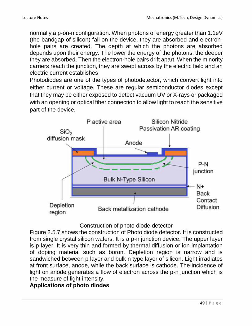
Lecture Notes Mechatronics (M.Tech, Design Dynamics)
49 | P a g e
normally a p-on-n configuration. When photons of energy greater than 1.1eV (the bandgap of silicon) fall on the device, they are absorbed and electron-hole pairs are created. The depth at which the photons are absorbed depends upon their energy. The lower the energy of the photons, the deeper they are absorbed. Then the electron-hole pairs drift apart. When the minority carriers reach the junction, they are swept across by the electric field and an electric current establishes
Photodiodes are one of the types of photodetector, which convert light into
either current or voltage. These are regular semiconductor diodes except
that they may be either exposed to detect vacuum UV or X-rays or packaged
with an opening or optical fiber connection to allow light to reach the sensitive
part of the device.
Construction of photo diode detector Figure 2.5.7 shows the construction of Photo diode detector. It is constructed from single crystal silicon wafers. It is a p-n junction device. The upper layer is p layer. It is very thin and formed by thermal diffusion or ion implantation of doping material such as boron. Depletion region is narrow and is sandwiched between p layer and bulk n type layer of silicon. Light irradiates at front surface, anode, while the back surface is cathode. The incidence of light on anode generates a flow of electron across the p-n junction which is the measure of light intensity. Applications of photo diodes
Lecture Notes Mechatronics (M.Tech, Design Dynamics)
50 | P a g e
Camera: Light Meters, Automatic Shutter Control, Auto-focus, Photographic Flash Control Medical: CAT Scanners - X ray Detection, Pulse Oximeters, Blood Particle Analyzers Industry • Bar Code Scanners • Light Pens • Brightness Controls • Encoders • Position Sensors • Surveying Instruments • Copiers - Density of Toner Safety Equipment • Smoke Detectors • Flame Monitors • Security Inspection Equipment - Airport X ray
• Intruder Alert - Security System
Automotive • Headlight Dimmer • Twilight Detectors • Climate Control - Sunlight Detector Communications • Fiber Optic Links • Optical Communications
• Optical Remote Control Module-III Signals, systems and Actuating Devices: Introduction to signals, systems and control system,
representation, linearization of nonlinear systems, time Delays, measures of system performance,
types of actuating devices selection. ;
SIGNAL:
• One can note that what is really being received through sensor and
what is being directed to the actuator is simply the ‘signal’.
• A signal is a time varying quantity conveying some information.
• The transducer output is simply the ‘signal’ and the actuator input is
also ‘signal’.
• Examples of signal include:
• Electrical signals

Lecture Notes Mechatronics (M.Tech, Design Dynamics)
51 | P a g e
– Voltages and currents in a circuit
• Acoustic signals
– Acoustic pressure (sound) over time
• Mechanical signals
– Velocity of a car over time
• Video signals
– Intensity level of a pixel (camera, video) over time
How is a Signal Represented?
• Mathematically, signals are represented as a function
of one or more independent variables.
• For instance a black & white video signal intensity is
dependent on x, y coordinates and time tf(x,y,t) Types of Signals
• Periodicsignals: a signal is periodic if it repeats itself after a fixed
period T, i.E. X(t) = x(t+t) for all t. A sin(t) signal is periodic.
• Even and odd signals: a signal is even if x(-t) = x(t) (i.E. It can be
reflected in the axis at zero). A signal is odd if x(-t) = -x(t). Examples
are cos(t) and sin(t) signals, respectively.
t
f(t

Lecture Notes Mechatronics (M.Tech, Design Dynamics)
52 | P a g e
• Deterministic signal: completely predictable, can be a deterministic function of the variables. – E.g., sin(t)., cos(t)…
Random signal: cannot predict the future values of the signal exactly; evolves uncertainties. Can only be described with statistical observations, the probability of the value at certain position.
– E.g., noise, vibration, stock market…
• Continuous-time signal It defined in the continuous time period. It is a function of a continuous independent variable. Note that the “continuous” refers to the variable t. The amplitude could be either continuous or discontinuous.
• Digital signal Digital signal is the signal that is both discrete in time, and quantized in amplitude.
• Discrete-time signal It defined only at a discrete set of values of independent variables. It can be obtained by sampling the continuous signal. Digital signal processing requires a discrete-time signal representation.
Why signal processing?
• A signal is composed is composed of many components.

Lecture Notes Mechatronics (M.Tech, Design Dynamics)
53 | P a g e
• Analysis that are being carried out is to know the amplitude,
frequency, and phase of the components either at a particular point
of time and/or in an interval.
• In order to take advantage of processing power of modern digital
processors or computers, it is necessary to convert the real world
analog signals in to an appropriate form, which can be stored and
processed by the use of digital systems and devices.
• Efficient make use of information, e.g. amplify or filter out
information, detect patterns, different domain information
• Better transmission and processing, e.g. distortions, prevent
interference
SYSTEM:
• A system (or plant) is a naturally occurring or man-made entity which
transforms cause(or inputs) into effects(or outputs).
• System behaviour can be modified by interactions with other systems.
• A cd player takes the signal on the cd and transforms it into a signal
sent to the loud speaker.
CONTROL SYSTEM:
A control system is a collection of components that is designed to drive
a given system (plant) with a given input to a desired output.
In a control system there is an interconnection between the constituent
components. These components may be electrical, mechanical,
hydraulic, pneumatic, etc.
• Modification of the behaviour of a system such that a desired
behaviour is achieved is called control.
• Controls are implemented by attaching a controller or compensator to
the plant. The resulting combined system is called a control system.
Lecture Notes Mechatronics (M.Tech, Design Dynamics)
54 | P a g e
• Control systems incorporate either human or machine controllers.
When the controller is machine based, it is called automatic control.
• Within any control system there are variables and functions.
• Variables can be either constant or may vary with respect to some
independent variable.
• Constant variables are called parameters.
• Varying variables are called signals.
Basic function of a control system are:
• To minimise the error between the actual and desired output.
• To minimise the time response to load changes in the system.
Requirement of a control system:
• Stability: for any change in the input signal, the output of the
system reads or makes its response at a reasonable value.
• Accuracy: the closeness of the measured value to the true value
is known as accuracy.
• Response: the quickness with which an instrument responds to
a change in the output signal is known as response.
• Sensitivity: The sensitivity measures how much change is
caused in the output bysmall changes to the reference input.
CLASSIFICATION OF CONTROL SYSTEM:
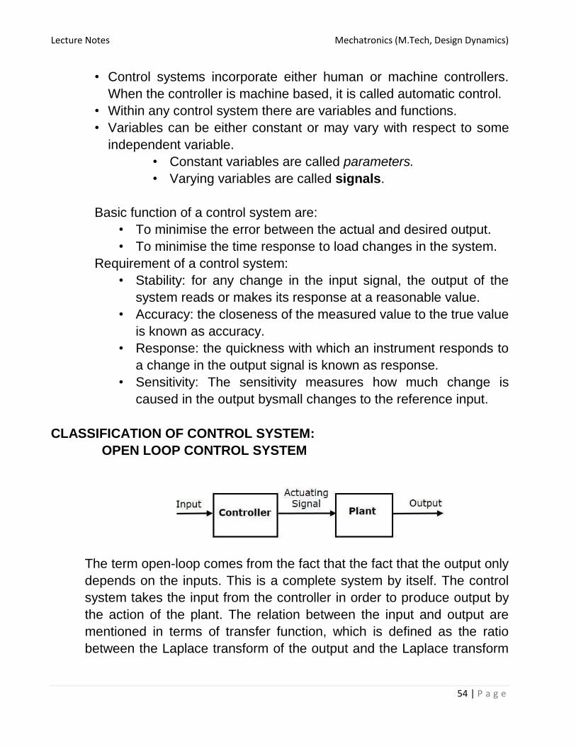
OPEN LOOP CONTROL SYSTEM
The term open-loop comes from the fact that the fact that the output only
depends on the inputs. This is a complete system by itself. The control
system takes the input from the controller in order to produce output by
the action of the plant. The relation between the input and output are
mentioned in terms of transfer function, which is defined as the ratio
between the Laplace transform of the output and the Laplace transform
Lecture Notes Mechatronics (M.Tech, Design Dynamics)
55 | P a g e
of the input. If the output is proportional to the input, the plant is called a
linear system.
In a basic open-loop control system the controller takes the reference
input called setpoint and outputs a control signal to the plant or process.
This configuration is also called feed-forward open-loop control system.
The controller is designed and turned using accurate model of the plant.
Any inaccuracy in the system model results discrepancy in the desired
output response.
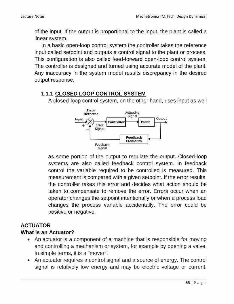
1.1.1 CLOSED LOOP CONTROL SYSTEM
A closed-loop control system, on the other hand, uses input as well
as some portion of the output to regulate the output. Closed-loop
systems are also called feedback control system. In feedback
control the variable required to be controlled is measured. This
measurement is compared with a given setpoint. If the error results,
the controller takes this error and decides what action should be
taken to compensate to remove the error. Errors occur when an
operator changes the setpoint intentionally or when a process load
changes the process variable accidentally. The error could be
positive or negative.
ACTUATOR
What is an Actuator?
An actuator is a component of a machine that is responsible for moving
and controlling a mechanism or system, for example by opening a valve.
In simple terms, it is a "mover".
An actuator requires a control signal and a source of energy. The control
signal is relatively low energy and may be electric voltage or current,
Lecture Notes Mechatronics (M.Tech, Design Dynamics)
56 | P a g e
pneumatic or hydraulic pressure, or even human power. Its main energy
source may be an electric current, hydraulic fluid pressure,
or pneumatic pressure. When it receives a control signal, an actuator
responds by converting the signal's energy into mechanical motion.
An actuator is the mechanism by which a control system acts upon an
environment. The control system can be simple (a fixed mechanical or
electronic system), software-based (e.g. a printer driver, robot control
system), a human, or any other input.
Different Types of Actuators
Mechanical Actuator
Pneumatic Actuator
Hydraulic Actuator
Electrical Actuator
Hybrid Actuator
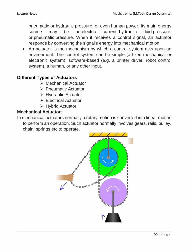
Mechanical Actuator:
In mechanical actuators normally a rotary motion is converted into linear motion
to perform an operation. Such actuator normally involves gears, rails, pulley,
chain, springs etc to operate.

Lecture Notes Mechatronics (M.Tech, Design Dynamics)
57 | P a g e
A basic example of a mechanical actuator is chain block hoisting weight in which mechanical motion of chain over the sprocket is utilized to lift a rated load.
Pneumatic Actuator:
Pneumatic energy is most commonly used for actuators used for main engine
controls. In this type, compressed air at high pressure is used which converts
this energy into either linear or rotary motion.
A pneumatic actuator converts energy formed by vacuum or compressed air at
high pressure into either linear or rotary motion. Pneumatic energy is
desirable for main engine controls because it can quickly respond in starting
and stopping as the power source does not need to be stored in reserve for
operation. Moreover, pneumatic actuators are safer, cheaper, and often
more reliable and powerful than other actuators.
Pneumatic actuators enable considerable forces to be produced from relatively
small pressure changes. These forces are often used with valves to move
diaphragms to affect the flow of liquid through the valve.
Hydraulic Actuator:
Unlike air, liquid cannot be compressed and hence hydraulics generates higher
energy than any other system. All systems involving high loads are operated
by hydraulic actuators in which oil pressure is applied on mechanical actuator
to give an output in terms of rotary or linear motion.
A hydraulic actuator consists of cylinder or fluid motor that uses hydraulic power
to facilitate mechanical operation. The mechanical motion gives an output in
terms of linear, rotatory or oscillatory motion. As liquids are nearly impossible
to compress, a hydraulic actuator can exert a large force. The drawback of
this approach is its limited acceleration.
The hydraulic cylinder consists of a hollow cylindrical tube along which a piston
can slide. The term single acting is used when the fluid pressure is applied
to just one side of the piston. The piston can move in only one direction, a
spring being frequently used to give the piston a return stroke. The
term double acting is used when pressure is applied on each side of the
piston; any difference in pressure between the two sides of the piston moves
the piston to one side or the other.
Electrical Actuator:

Lecture Notes Mechatronics (M.Tech, Design Dynamics)
58 | P a g e
It is one of the cleanest and readily available forms of actuating system as it
does not involve oil; as there is no need to compress air, hence no extra
machinery. Electrical energy is always available on ship. The electrical
energy is used to actuate a mechanical system using magnetic field i.e. EMF.
Basic example are electrical motor operated valve and magnetic valve
actuator or solenoid valve.
An electric actuator is powered by a motor that converts electrical energy into
mechanical torque. The electrical energy is used to actuate equipment such
as multi-turn valves. Additionally, a brake is typically installed above the
motor to prevent the media from opening valve. If no brake is installed, the
actuator will uncover the opened valve and rotate it back to its closed
position. If this continues to happen, the motor and actuator will eventually
become damaged.[6] It is one of the cleanest and most readily available forms
of actuator because it does not directly involve oil or other fossil fuels.
Hybrid Actuators:
These are mixture of some of the above systems which control the mechanical
part of the system. Common example is a thermo hydraulic Electronic
actuator used in operating valves in hot water system, wherein hot water
liquid is used along with electronic system acting as control for the valve
Examples of actuators
Comb drive
Digital micromirror device
Electric motor
Electroactive polymer
Hydraulic cylinder
Piezoelectric actuator
Pneumatic actuator
Screw jack
Servomechanism
Solenoid
Stepper motor
Shape-memory alloy
Hydraulic actuators
Performance metrics
Performance metrics or actuators include speed, acceleration, and force
(alternatively, angular speed, angular acceleration, and torque), as well

Lecture Notes Mechatronics (M.Tech, Design Dynamics)
59 | P a g e
as energy efficiency and considerations such as mass, volume, operating
conditions, and durability, among others.
Force
When considering force in actuators for applications, two main metrics should
be considered. These two are static and dynamic loads. Static load is the
force capability of the actuator while not in motion. Conversely, the dynamic
load of the actuator is the force capability while in motion.
Speed
Speed should be considered primarily at a no-load pace, since the speed will
invariably decrease as the load amount increases. The rate the speed will
decrease will directly correlate with the amount of force and the initial speed.
Operating conditions
Actuators are commonly rated using the standard IP Code rating system. Those
that are rated for dangerous environments will have a higher IP rating than
those for personal or common industrial use.
Durability
This will be determined by each individual manufacturer, depending on usage
and quality.
ACTUATING DEVICES
Actuating devices in access control systems directly reduce or give access
towards different areas of controlled territory or the object. Steered latches,
locks, turnstiles of different variants, elevators, entrance security cabins,
automatic gates and lots of others are used as actuating devices. Control of
actuating devices is fulfilled by the controllers of access control system. The
selection of actuating device depends upon the object’s type, upon the
equipment’s service conditions, specifics of the mode and upon security
requirements on the object. Depending upon these and some other factors
the variant of actuating devices’ access control system can differ a lot.
Electromechanical locks and latches
Electromechanical locks and latches operate quite simply. In
electromechanical catchers the electromagnet is used, which under tension
drags the locking device enabling opening of the door. In powerful locks of
vault type special electric drive is used for opening-closing of the locking

Lecture Notes Mechatronics (M.Tech, Design Dynamics)
60 | P a g e
pins. If building object is planned to be equipped by the access control
system electromechanical locks should be better used as actuating devices.
In case of fitting put of the operating object electromechanical latches should
be better chosen, which can be utilized alongside with already installed
locking devices.
Electromagnetic locks
Electromagnetic lock is a powerful magnet installed on the doorframe and a
metal plate fixed on the door. The electromagnet is supplied by electric hold-
on current; it attracts and holds the door with the plate.
Electromagnets used in electromagnet locks can have retentivity power up to
one ton and more. While door-open signal injection electromagnet power is
switched off and the door can be freely opened. Doors with electromagnetic
locks should be by all means equipped by the door closers for resetting into
initial position.
Turnstiles
Turnstile is a revolute system for access control to the secured territory.
Turnstiles thanks to their construction have high throughput efficiency; that
is why they are installed in places of mass pass onto enclosed territory –
checkpoints, railway/metro line stations and i.e. In ordinary state the turnstile
blocks the passage, while open-passage signal injection the turnstile can
freely rotate about its axis enabling the pass onto the territory of the object.
There are half- and full-length turnstiles. Half-length turnstiles can be got over,
that is why they are used on the objects with low and moderate security
requirements and are installed in direct closeness to the watchpost. For
important objects full-length turnstiles should be better used, they thoroughly
block the passage ability to the territory.
Entrance security cabins
Entrance security cabins like turnstiles are intended for installation in places
of mass pass to the secured territory, but entrance security cabins supply
intensified security level having at the same time lower flow capacity.
Entrance security cabin of a tambour type is the premises with two doors
among which only one can remain open.
After entrance to the security cabin, the first door closes and only after
controller’s access admittance signal the second door opens. Entrance
security cabin of the tambour type meets high security requirements but has
minimal flow capacity – 8/12 persons per minute.
Lecture Notes Mechatronics (M.Tech, Design Dynamics)
61 | P a g e
To increase throughput capacity entrance security cabins of rotary type are
used; one rotary door is used in them, reminding turnstile by its construction.
Rotary entrance security cabins can meet high security requirements, at the
same time their flow capacity is two times higher than entrance security
cabins of tambour type-18/22 persons per minute.
To increase efficiency of entrance security cabins variety of certain devices -
input metal detectors for weapons disclosure and weighing systems, averting
simultaneous passage of more than one person are used in their
construction. Entrance security cabins are manufactured of armor-coated
glass or of the metal.
Elevators
Elevators are also used as one of the variants of actuating devices in access
control systems. Elevator is an entrance security cabin by its essence from
which a person can get only to those floors where he has access
authorization. Elevator’s stop on another floors and door opening is
forbidden by access control system.
Automatic gates and turnstiles
Automatic gates and turnstiles are used for limitation of free automobile
transport movement. Automatic turnstiles of different constructions as well
as automatic gates of various versions – swinging, sliding, upward acting
gates and roller shutters are used for this purpose. On the ordinary objects
gates or turnstiles are enough means for transport’s encroachment
restriction to the enclosed territory. On the objects with high security level
anti-ram barriers for emergency automobile braking are used further to the
gates and turnstiles.
Other examples
Video surveillance systems
Perimeter security systems
Alarm systems
Access control systems
o Actuating devices
o Controllers
o Entryphones
o Keys and readers Real time interfacing: Introduction, Element of a Data Acquisition and control system,
overview of the I/O process. Installation of the I/O card and software.

Lecture Notes Mechatronics (M.Tech, Design Dynamics)
62 | P a g e
Real time interface
What is real time?
Real-time is a quantitative notion of time. Real-time is measured using a physical (real) clock.
In contrast to real time, logical time (also known as virtual time) deals with a qualitative notion of time and is expressed using event ordering relations such as before, after, sometimes, eventually, precedes, succeeds, etc.
A system is called a real-time system, when we need quantitative expression of time (i.e. real-time) to describe the behavior of the system.
Basic model of RTI
Sensor: converts some physical characteristic of its environment into
electrical signals. An example of a sensor is a photo-voltaic cell which
converts light energy into electrical energy. A wide variety of

Lecture Notes Mechatronics (M.Tech, Design Dynamics)
63 | P a g e
temperature and pressure sensors are also used. A temperature
sensor typically operates based on the principle of a thermocouple.
Actuator: Device that takes its inputs from the output interface of a
computer and converts these electrical signals into some physical
actions on its environment.
Physical actions :- motion, change of thermal, electrical, pneumatic,
or physical characteristics of some objects.
Eg:- motor
Signal Conditioning Units:
Electrical signals produced by a computer can rarely be used to
directly drive an actuator. The computer signals usually need
conditioning before they can be used by the actuator. This is termed
output conditioning. Input conditioning is required to be carried out
on sensor signals before they can be accepted by the computer.
-Important types of conditioning carried out on raw signals
generated by sensors and digital signals generated by computers
1. Voltage amplifier
2. Voltage level shifting
3. Frequency range shifting and filtering
4. Signal mode conversion
Interface Unit: Normally commands from the CPU are delivered to the
actuator through an output interface. An output interface converts
the stored voltage into analog form and then outputs this to the
actuator circuitry. This of course would require the value generated to
be written on a register
Characteristics

Lecture Notes Mechatronics (M.Tech, Design Dynamics)
64 | P a g e
Time constraints
New Correctness Criterion
Embedded
Safety-Criticality
Concurrency
Distributed and Feedback Structure
Task criticality
Custom hardware
Reactive
Stability
Exception handling
Types of real time task A real-time task can be classified into
Hard real-time task
Soft real-time task
Firm real-time task
Hard Real-Time Tasks
A hard real-time task is one that is constrained to produce its results within
certain predefined time bounds. The system is considered to have failed
whenever any of its hard real-time tasks does not produce its required results
before the specified time bound.
Firm Real-Time Tasks
Every firm real-time task is associated with some predefined deadline before
which it is required to produce its results. 1.7.3. Soft Real-Time Tasks

Lecture Notes Mechatronics (M.Tech, Design Dynamics)
65 | P a g e
Soft real-time tasks also have time bounds associated with them.
However, unlike hard and firm real-time tasks, the timing constraints on soft
real-time tasks are not expressed as absolute values. Instead, the
constraints are expressed either in terms of the average response times
required.
Applications
Industrial Applications
Example 1: Chemical Plant Control
Chemical plant control systems are essentially a type of process control
application. In an automated chemical plant, a real-time computer
periodically monitors plant conditions.
Example 2: Automated Car Assembly Plant
Ex-3 Medical
Robot Used in Recovery of Displaced Radioactive Material
Ex-4 Peripheral equipments
Ex 5: Laser Printer
Ex-6. Internet and Multimedia Applications video conferencing
Elements of data acquisition
What is Data acquisition? Data acquisition systems are used by most engineers and scientists for
laboratory research, industrial control, test and measurement to input and
output data to and from a computer.
Elements
Sensor
Signal conditioning
Analog input(A/D) board

Lecture Notes Mechatronics (M.Tech, Design Dynamics)
66 | P a g e
Computer
Output interface
DAQ BLOCK DIAGRAM
Sensor
Measures physical variables such as temperature, strain, flow force and
motion
Signal conditioning:-
To convert sensor outputs into signals readable by analog input board (A/D)
in the PC
Analog Input (A/D) board:-
Converts these signals into digital format usable by PC
Computer:

Lecture Notes Mechatronics (M.Tech, Design Dynamics)
67 | P a g e
A computer with appropriate software to process, analyze and lock the
data to the disk. Such software may also provide a graphical display of
the data.
Output Interface:
Provides an appropriate process control response
Module-Iv Application of software in Mechatronics: Advance application in Mechantronics. Sensors for
conditioning Monitoring, Mechatronic Control in Automated Manufacturing, Micro sensors in Mechatronics. Case studies and examples in Data Acquisition and control. Automated manufacturing etc.
Application of software in Mechatronics Modelling, analysis, design, data acquisition, and control are important
activities within the field of Mechatronics. Computer software tools and environments are available for effectively
carrying out, both at the learning level and at the professional application level.
MATLAB is an interactive computer environment with a high-level language and tools for scientific and technical computation, modelling and simulation, design, and control of dynamic systems.
SIMULINK is a graphical environment for modelling, simulation, and analysis of dynamic systems, and is available as an extension to MATLAB.

Lecture Notes Mechatronics (M.Tech, Design Dynamics)
68 | P a g e
LabVIEW is graphical programming language and a program development environment for data acquisition, processing, display, and instrument control.
Simulink provides a graphical environment for modeling, simulating, and analyzing linear and nonlinear dynamic systems. First a suitable block diagram model of the system is developed on the computer screen, and stored.
The SIMULINK environment provides almost any block that is used in a typical block diagram. These include transfer functions, integrators, gains, summing junctions, inputs (i.e., source blocks), and outputs (i.e., graph blocks or scope blocks).
Such a block may be selected and inserted into the workspace as many times as needed, by clicking and dragging using the mouse. These blocks may be connected as required, using directed lines.
A block may be opened by clicking on it, and the parameter values and text may be inserted or modified as needed. Once the simulation block diagram is generated in this manner, it may be run and the response may be observed through an output block (graph block or scope block).
There are two types of elements in SIMULINK: blocks and lines. Blocks are used to generate (or input), modify, combine, output, and display signals. Lines are used to transfer signals from one block to another.
Starting Simulink
First enter the MATLAB environment. You will see the MATLAB command prompt >>. To start SIMULINK, enter the command: simulink. Alternatively, you may click on the “Simulink” button at the top of the MATLAB command window.
Basic Elements:- There are two types of elements in SIMULINK: blocks and lines. Blocks
are used to generate (or input), modify, combine, output, and display signals. Lines are used to transfer signals from one block to another.
Blocks:- The subfolders below the SIMULINK folder show the general classes of
blocks available for use. They are • Continuous: Linear, continuous-time system elements (integrators,
transfer functions, state-space models, etc.) A signal can be either a scalar signal (single signal) or a vector signal
(several signals in parallel). The lines used to transmit scalar signals and vector signals are identical; whether it is a scalar or vector is determined by the blocks connected by the line.
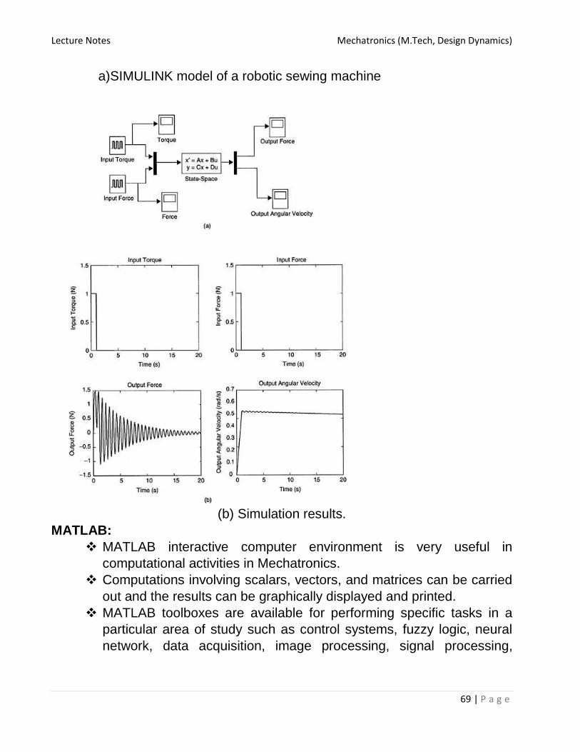
Lecture Notes Mechatronics (M.Tech, Design Dynamics)
69 | P a g e
a)SIMULINK model of a robotic sewing machine
(b) Simulation results.
MATLAB:
MATLAB interactive computer environment is very useful in
computational activities in Mechatronics.
Computations involving scalars, vectors, and matrices can be carried
out and the results can be graphically displayed and printed.
MATLAB toolboxes are available for performing specific tasks in a
particular area of study such as control systems, fuzzy logic, neural
network, data acquisition, image processing, signal processing,

Lecture Notes Mechatronics (M.Tech, Design Dynamics)
70 | P a g e
system identification, optimization, model predictive control, robust
control, and statistics.
Mathematical computations can be done by using the MATLAB
command window. Simply type in the computations against the
MATLAB prompt “>>” as illustrated next.
An example of a simple computation using MATLAB is given below.
>> x=2; y=-3;
>> z=x^2-x*y+4
z=-14
MATLAB Arithmetic Operations
Symbol Operation
+ Addition
- Subtraction
* Multiplication
/ Division
^ Power
Useful Mathematical Functions in MATLAB
Function Description
abs() Absolute value/magnitude
acos() Arc-cosine (inverse cosine)
acosh() Arc-hyperbolic-cosine
asin() Arc-sine
atan() Arc-tan
cos() Cosine
cosh() Hyperbolic cosine
exp() Exponential function
imag() Imaginary part of a complex number
log() Natural logarithm
log10() Log to base 10 (common log)
real() Real part of a complex number
sign() Signum function
sin() Sine
sqrt() Positive square root
tan() Tan function

Lecture Notes Mechatronics (M.Tech, Design Dynamics)
71 | P a g e
Some Relational Operations
Operator Description
< Less than
<= Less than or equal to
> Greater than
>= Greater than or equal to
= = Equal to
~= Not equal to
Basic Logical Operations
Operator Description
& AND
| OR
~ NOT
LABVIEW
• LabVIEW or Laboratory Virtual Engineering Workbench is a product
of National Instruments. It is a software development environment for
data acquisition, instrument control, image acquisition, motion control,
and presentation.
• LabVIEW is a complied graphical environment, which allows the user
to create programs graphically through wired icons similar to creating
a flowchart.
Working with LabVIEW:- • As a software centered system, LabVIEW resides in a desktop
computer, laptop or PXI as an application where it acts as a set of
virtual instruments (VIs), providing the functionality of traditional
hardware instruments such as oscilloscopes.
• Comparing to physical instruments with fixed functions, LabVIEW VIs
are flexible and can easily be reconfigured to different applications.
• It is able to interface with various hardware devices such as GPIB, data
acquisition modules, distributed I/O, image acquisition, and motion
control, making it a modular solution.
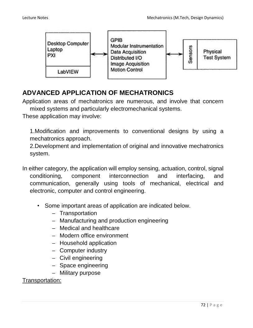
Lecture Notes Mechatronics (M.Tech, Design Dynamics)
72 | P a g e
ADVANCED APPLICATION OF MECHATRONICS
Application areas of mechatronics are numerous, and involve that concern
mixed systems and particularly electromechanical systems.
These application may involve:
1.Modification and improvements to conventional designs by using a
mechatronics approach.
2.Development and implementation of original and innovative mechatronics
system.
In either category, the application will employ sensing, actuation, control, signal
conditioning, component interconnection and interfacing, and
communication, generally using tools of mechanical, electrical and
electronic, computer and control engineering.
• Some important areas of application are indicated below.
– Transportation
– Manufacturing and production engineering
– Medical and healthcare
– Modern office environment
– Household application
– Computer industry
– Civil engineering
– Space engineering
– Military purpose
Transportation:
Lecture Notes Mechatronics (M.Tech, Design Dynamics)
73 | P a g e
There are two field used in the mechatronics system
1. Ground transportation
2. Air transportation
1. Ground transportation:
In ground transportation in particular automobiles, trains, and automated
transit systems use mechatronics devices. They include
1. Airbag deployment systems
2 .Antilock braking systems(ABS)
3. Cruise control system
4. Active suspension system
5. Navigation
6. Control in intelligent vehicular highway systems(IVHS)

Lecture Notes Mechatronics (M.Tech, Design Dynamics)
74 | P a g e
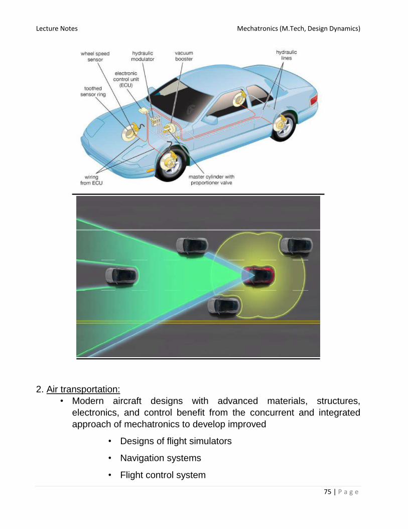
Lecture Notes Mechatronics (M.Tech, Design Dynamics)
75 | P a g e
2. Air transportation:
• Modern aircraft designs with advanced materials, structures,
electronics, and control benefit from the concurrent and integrated
approach of mechatronics to develop improved
• Designs of flight simulators
• Navigation systems
• Flight control system

Lecture Notes Mechatronics (M.Tech, Design Dynamics)
76 | P a g e
• Landing gear mechanisms
• Travelers comfort aids

Lecture Notes Mechatronics (M.Tech, Design Dynamics)
77 | P a g e
Manufacturing and production engineering:
• Manufacturing And Production Engineering is another broad field that
uses mechatronics technologies and systems.
– Factory robots (for welding, spray painting, assembly,
inspection, etc.)
– Automated guided vehicles(AGVs)
– Modern computer-numerical control (CNC) machine tolls
– Machining centre
– Rapid(and virtual) prototyping systems
– Micromachining systems

Lecture Notes Mechatronics (M.Tech, Design Dynamics)
78 | P a g e
Medical and healthcare;
• General patient care are being developed and used.
– Patient transit devices
• In medical and healthcare application, robotic technologies for
example
– Surgery
– Rehabilitation(regain or improve neurocognitive function that
has been lost or diminished)
– Drug dispensing(intermediary drug)
– Various diagnostic probes
– Scanners
– Beds
–
Exercise machines
Modern office environment;
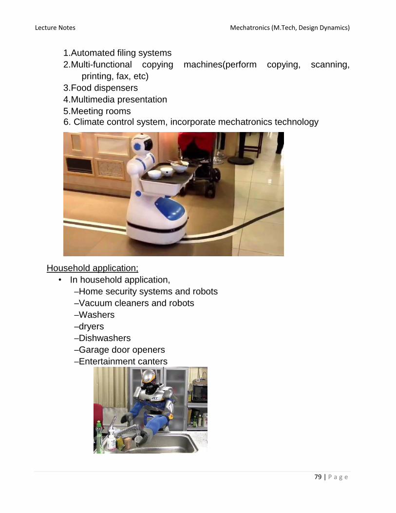
Lecture Notes Mechatronics (M.Tech, Design Dynamics)
79 | P a g e
1.Automated filing systems
2.Multi-functional copying machines(perform copying, scanning,
printing, fax, etc)
3.Food dispensers
4.Multimedia presentation
5.Meeting rooms
6. Climate control system, incorporate mechatronics technology
Household application;
• In household application,
– Home security systems and robots
– Vacuum cleaners and robots
– Washers
– dryers
– Dishwashers
– Garage door openers
– Entertainment canters

Lecture Notes Mechatronics (M.Tech, Design Dynamics)
80 | P a g e
Computer industry;
• In this computer industry
– Hard disk drives(HDD)
– Disk retrieval ejection devices
– Cooling fan
Civil engineering;
• In civil engineering application
– Cranes
– Excavators
– Earth removal.
– Mixing and so on, will improve their performance by adopting a
mechatronic design approach
Space application;
• In space application
– Mobile robots such as NANA’s mars exploration rover
– Space station robots – Space vehicles are fundamentally mechatronics systems

Lecture Notes Mechatronics (M.Tech, Design Dynamics)
81 | P a g e
Military Applications:
• In military application
– Bomb detection robot
– Surveillance vehicles
– Drones