Lecture 3 Data Link Layer - Digital Data Communication
14
10/9/2013 CpE400/ECG600 Fall 2013 1 DATA AND COMPUTER COMMUNICATIONS Mei Yang Based on Lecture slides by William Stallings Lecture 3 Data Link Layer - Digital Data Communication Techniques 1 ASYNCHRONOUS AND SYNCHRONOUS TRANSMISSION timing problems require a mechanism to synchronize the transmitter and receiver receiver samples stream at bit intervals if clocks not aligned and drifting will sample at wrong time after sufficient bits are sent two solutions to synchronizing clocks asynchronous transmission synchronous transmission
Transcript of Lecture 3 Data Link Layer - Digital Data Communication

10/9/2013
CpE400/ECG600 Fall 2013 1
DATA AND COMPUTER COMMUNICATIONS
Mei Yang
Based on Lecture slides by William Stallings
Lecture 3 Data Link Layer -Digital Data Communication
Techniques
1
ASYNCHRONOUS AND SYNCHRONOUSTRANSMISSION
timing problems require a mechanism to synchronize the transmitter and receiver receiver samples stream at bit intervals if clocks not aligned and drifting will sample at wrong
time after sufficient bits are sent
two solutions to synchronizing clocks asynchronous transmission synchronous transmission

10/9/2013
CpE400/ECG600 Fall 2013 2
ASYNCHRONOUS TRANSMISSION
data are transmitted one character at a time each character is 5 to 8 bits in length receiver has the opportunity to resynchronize at the
beginning of each new character
simple and cheap requires overhead of 2 or 3 bits per character (~20%)
the larger the block of bits, the greater the cumulative timing error
good for data with large gaps (keyboard)
ASYNCHRONOUS TRANSMISSION

10/9/2013
CpE400/ECG600 Fall 2013 3
ASYNCHRONOUS - BEHAVIOR
simple cheapoverhead of 2 or 3 bits per char (~20%)good for data with large gaps (keyboard)
SYNCHRONOUS TRANSMISSION
block of data transmitted sent as a frame clocks must be synchronized
can use separate clock line or embed clock signal in data
need to indicate start and end of block use preamble and postamble
more efficient (lower overhead) than async
10/9/2013
CpE400/ECG600 Fall 2013 4
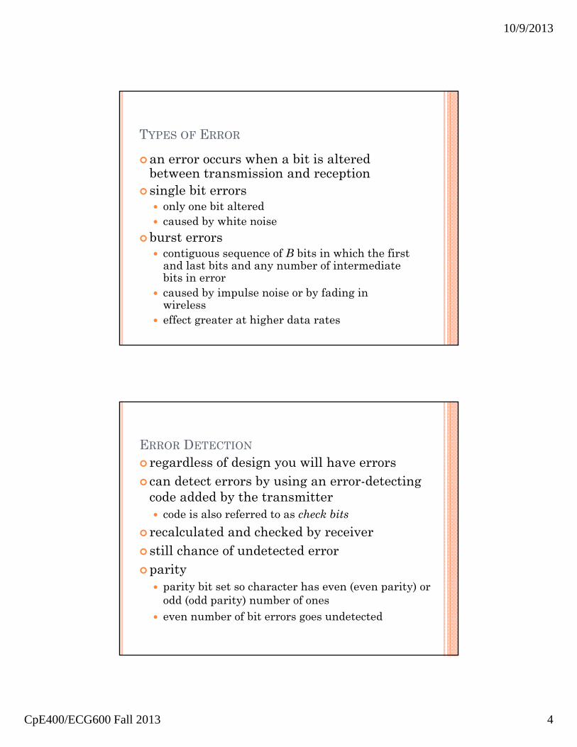
TYPES OF ERROR
an error occurs when a bit is altered between transmission and reception
single bit errors only one bit altered caused by white noise
burst errors contiguous sequence of B bits in which the first
and last bits and any number of intermediate bits in error
caused by impulse noise or by fading in wireless
effect greater at higher data rates
ERROR DETECTION
regardless of design you will have errors can detect errors by using an error-detecting
code added by the transmitter code is also referred to as check bits
recalculated and checked by receiver still chance of undetected errorparity
parity bit set so character has even (even parity) or odd (odd parity) number of ones
even number of bit errors goes undetected
10/9/2013
CpE400/ECG600 Fall 2013 5
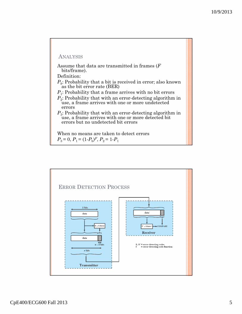
ANALYSIS
Assume that data are transmitted in frames (Fbits/frame).
Definition:Pb: Probability that a bit is received in error; also known
as the bit error rate (BER)P1: Probability that a frame arrives with no bit errorsP2: Probability that with an error-detecting algorithm in
use, a frame arrives with one or more undetected errors
P3: Probability that with an error-detecting algorithm in use, a frame arrives with one or more detected bit errors but no undetected bit errors
When no means are taken to detect errorsP3 = 0, P1 = (1-Pb)F, P2 = 1-P1
ERROR DETECTION PROCESS

10/9/2013
CpE400/ECG600 Fall 2013 6
PARITY CHECK
the simplest error detecting scheme is to append a parity bit to the end of a block of data Even parity – even number of 1s
Used for synchronous transmission
Odd parity – odd number of 1sUsed for asynchronous transmission
if any even number of bits are inverted due to error, an undetected error occurs
CYCLIC REDUNDANCY CHECK
one of most common and powerful checks for block of k bits transmitter generates
an n-k bit frame check sequence (FCS) transmits n bits which is exactly divisible
by some number receiver divides frame by that number
if no remainder, assume no error for math, see Stallings chapter 6

10/9/2013
CpE400/ECG600 Fall 2013 7
MODULO 2 ARITHMETIC
Modulo 2 arithmetic uses binary addition with no carries, which is just the exclusive-OR (XOR) operation.
Definition:T = n-bit frame to be transmitted
D = k-bit block of data, or message, the first k bits of TF = (n-k)-bit FCS, the last (n-k) bits of TP = pattern of n-k+1 bits
Let T = 2n-kD + R, whereThen T/P = Q + R/P + R/P = Q
P
RQ
P
Dkn
2
POLYNOMIALS
Express all values as polynomials in a dummy variable X with binary coefficients corresponding to the bits in the binary number
)()()(
)(
)()(
)(
)(
XRXDXXT
XP
XRXQ
XP
XDX
kn
kn

10/9/2013
CpE400/ECG600 Fall 2013 8
SELECTION OF P(X)
All single-bit errors, if P(X) has more than one nonzero term
All double-bit errors, as long as P(X) is a primitive polynomial, with maximum exponent L, and the frame length is less than 2L-1
Any odd number of errors, as long as P(X)contains a factor (X+1)
Any burst errors for which the length of the burst is ≤ n-k, i.e., the length of the FCS
A fraction (1-2-(n-k-1)) of error bursts of length n-k+1
A fraction (1-2-(n-k)) of error bursts greater than n k+1
SELECTION OF P(X)
Four versions of P(X) are widely usedCRC-12 = X12 + X11 + X3 + X2 + X + 1CRC-16 = X16 + X15 + X2 + 1CRC-CCITT = X16 + X12 + X5 + 1CRC-32 = X32 + X26 + X23 + X22 + X16 + X12
+ X11 + X10 + X8 + X7 + X5 + X4 + X2 + X + 1

10/9/2013
CpE400/ECG600 Fall 2013 9
DIGITAL LOGIC
The CRC can be implemented as a dividing circuit consisting of XOR gates and a shift register.
EXAMPLE
Example: P(x) = X5 + X4 + X2 + 1

10/9/2013
CpE400/ECG600 Fall 2013 10
ERROR CORRECTION
correction of detected errors usually requires data block to be retransmitted
not appropriate for wireless applications bit error rate is high causing lots of retransmissions when propagation delay long (satellite) compared with frame
transmission time, resulting in retransmission of frame in error plus many subsequent frames
need to correct errors on basis of bits received codeword
on the transmission end each k-bit block of data is mapped into an n-bit block (n > k) using a forward error correction (FEC) encoder
ERROR CORRECTION PROCESS

10/9/2013
CpE400/ECG600 Fall 2013 11
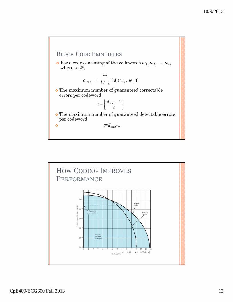
HOW ERROR CORRECTION WORKS
adds redundancy to transmitted message can deduce original despite some errorsmeans have reduced effective data rateeg. block error correction code
BLOCK CODE PRINCIPLES
Hamming distance d(v1, v2) between two n-bit binary sequences v1 and v2 is the number of bits in which v1 and v2 disagree
The design of a block code is equivalent to the design of a function of the form vc=f(vd), where vd is a vector of k data bits and vc is a vector of n codeword bits
Redundancy of the code: (n-k)/kCode rate: k/n
10/9/2013
CpE400/ECG600 Fall 2013 12
BLOCK CODE PRINCIPLES
)],([min
min ji wwdjid
For a code consisting of the codewords w1, w2, …, ws, where s=2n,
2
1mindt
The maximum number of guaranteed correctable errors per codeword
The maximum number of guaranteed detectable errors per codeword
t=dmin-1
HOW CODING IMPROVESPERFORMANCE

10/9/2013
CpE400/ECG600 Fall 2013 13
LINE CONFIGURATION - TOPOLOGY
• refers to the physical arrangement of stations • refers to the physical arrangement of stations
topology
• such as between two routers / computers• such as between two routers / computers
point to point - two stations
• traditionally mainframe computer and terminals
• now typically a local area network (LAN)
• traditionally mainframe computer and terminals
• now typically a local area network (LAN)
multi point - multiple stations
LINE CONFIGURATION - TOPOLOGY

10/9/2013
CpE400/ECG600 Fall 2013 14
LINE CONFIGURATION - DUPLEX
classify data exchange as half or full duplex
half duplex (two-way alternate) only one station may transmit at a time requires one data path
full duplex (two-way simultaneous) simultaneous transmission and reception
between two stations requires two data paths
separate media or frequencies used for each direction
or echo canceling
SUMMARY
asynchronous & synchronous transmission asynchronous
data transmitted one character at a time
synchronousblock of bits transmitted in steady stream without start
and stop codes
error detection and correction single bit error and error burst error detecting codes
parity and cyclic redundancy check (CRC)
line configurations topology full duplex and half duplex