UNIT-II Computer Network Data Link Layer. Data Link Layer Prepared by - ROHIT KOSHTA Data Link Layer...
32
UNIT-II Computer Network Data Link Layer
-
Upload
antonia-butler -
Category
Documents
-
view
236 -
download
1
Transcript of UNIT-II Computer Network Data Link Layer. Data Link Layer Prepared by - ROHIT KOSHTA Data Link Layer...

UNIT- I I
Computer NetworkData Link Layer

Prepared by - ROHIT KOSHTA
Data Link Layer
Data Link Layer is second layer of OSI reference model and is placed above the physical layer.
Deals with frame formation, flow control, error control, addressing and link management.

Prepared by - ROHIT KOSHTA
Functions of Data Link Layer Data Transfer
Transfer of data from physical layer to network layer
Framing Data-link layer takes packets from Network Layer and encapsulates them into Frames.
At receiver’ end, data link layer picks up signals from hardware and assembles them into frames.
Frame synchronization The source machine sends data in blocks called frames to the destination machine.
The starting and end of each frame should be recognized by the destination machine.
Flow control The source machine must not send data frames at a faster rate than the destination
machine can accept.
Error control The errors made in bits during transmission from source to destination machines must
be detected and corrected.
Addressing On a multipoint line, such as many machines connected together (LAN), the identity of
the individual machines must be specified while transmitting the data frames.
Link Management The initiation, maintenance and termination of the link between the source and
destination.

Prepared by - ROHIT KOSHTA
Services provided by Data Link Layer
Unacknowledged connectionless serviceAcknowledged connectionless serviceAcknowledged connection oriented service

Prepared by - ROHIT KOSHTA
Framing in Data Link Layer
Framing methods: Character count Starting and ending characters, with character
stuffing Starting and ending flags with bit stuffing Physical layer coding violations
Prepared by - ROHIT KOSHTA
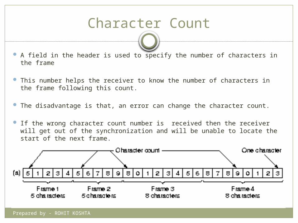
Character Count
A field in the header is used to specify the number of characters in the frame
This number helps the receiver to know the number of characters in the frame following this count.
The disadvantage is that, an error can change the character count.
If the wrong character count number is received then the receiver will get out of the synchronization and will be unable to locate the start of the next frame.

Prepared by - ROHIT KOSHTA
Character Stuffing
The problem of character count method is solved here by using a starting character before the starting of each frame and an ending character at the end of each frame.
Each frame is preceded by the transmission of ASCII character sequence DLE STX (DLE stands for Data Link Escape and ETX stands for Start of TeXt).
After each frame the ASCII character sequence DLE ETX is transmitted (DLE stands for Data Link Escape and ETX stands for End of TeXt).
So if the receiver loses the synchronization, it just has to search for the DLE STX or DLE ETX characters to return back to track.

Prepared by - ROHIT KOSHTA
Bit Stuffing
Whenever the sender data link layer detects the presence of five consecutive ones in the data, it automatically stuffs a 0 bit into the outgoing bit stream. This is called stuffing.
When a receiver detects presence of five consecutive ones in the received bit stream, it automatically deletes the 0 bit following the five ones. This is called de-stuffing.

Prepared by - ROHIT KOSHTA
Physical Coding Violation
This method of framing is applicable only to the networks in which the encoding on the physical medium contains some redundancy.
Some LANs encode each bit of data using two physical nits.
Normally a 1 bit is encoded into a 10 pair and a 0 bit is encoded into a 01 pair.
Prepared by - ROHIT KOSHTA
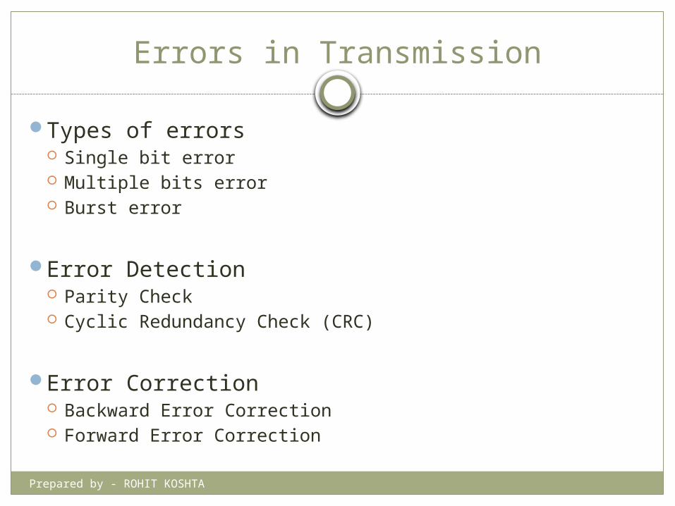
Errors in Transmission
Types of errors Single bit error Multiple bits error Burst error
Error Detection Parity Check Cyclic Redundancy Check (CRC)
Error Correction Backward Error Correction Forward Error Correction

Prepared by - ROHIT KOSHTA
Types of Errors
There may be three types of errors: Single bit error
In a frame, there is only one bit, anywhere though, which is corrupt.
Multiple bits error Frame is received with more than one bits in corrupted
state.
Burst error Frame contains more than1 consecutive bits corrupted.

Prepared by - ROHIT KOSHTA
Parity Check
One extra bit is sent along with the original bits to make number of 1s either even in case of even parity, or odd in case of odd parity.
The sender while creating a frame counts the number of 1s in it. For example, if even parity is used and number of 1s is even then one bit with value 0 is added. This way number of 1s remains even. If the number of 1s is odd, to make it even a bit with value 1 is added.
The receiver simply counts the number of 1s in a frame. If the count of 1s is even and even parity is used, the frame is considered to be not-corrupted and is accepted. If the count of 1s is odd and odd parity is used, the frame is still not corrupted.
If a single bit flips in transit, the receiver can detect it by counting the number of 1s. But when more than one bits are errorneous, then it is very hard for the receiver to detect the error.

Prepared by - ROHIT KOSHTA
Cyclic Redundancy Check (CRC)
CRC is a different approach to detect if the received frame contains valid data.
This technique involves binary division of the data bits being sent.
The divisor is generated using polynomials.
The sender performs a division operation on the bits being sent and calculates the remainder.
Before sending the actual bits, the sender adds the remainder at the end of the actual bits.
Actual data bits plus the remainder is called a codeword.
The sender transmits data bits as codewords.

Prepared by - ROHIT KOSHTA
Cyclic Redundancy Check (CRC)
At the other end, the receiver performs division operation on codewords using the same CRC divisor.
If the remainder contains all zeros the data bits are accepted, otherwise it is considered as there some data corruption occurred in transit.

Prepared by - ROHIT KOSHTA
Error Correction
In the digital world, error correction can be done in two ways: Backward Error Correction When the receiver
detects an error in the data received, it requests back the sender to retransmit the data unit.
Forward Error Correction When the receiver detects some error in the data received, it executes error-correcting code, which helps it to auto-recover and to correct some kinds of errors.

Prepared by - ROHIT KOSHTA
Flow Control
When a data frame (Layer-2 data) is sent from one host to another over a single medium, it is required that the sender and receiver should work at the same speed.
What if the speed (hardware/software) of the sender or receiver differs? If sender is sending too fast the receiver may be overloaded, (swamped) and data may be lost.
Two types of mechanisms can be deployed to control the flow: Stop and Wait Sliding Window

Prepared by - ROHIT KOSHTA
Stop and Wait
This flow control mechanism forces the sender after transmitting a data frame to stop and wait until the acknowledgement of the data-frame sent is received.

Prepared by - ROHIT KOSHTA
Sliding Window
In this flow control mechanism, both sender and receiver agree on the number of data-frames after which the acknowledgement should be sent.
As we learnt, stop and wait flow control mechanism wastes resources, this protocol tries to make use of underlying resources as much as possible.

Prepared by - ROHIT KOSHTA
Error Control
Requirements for error control mechanism: Error detection - The sender and receiver, either both or
any, must ascertain that there is some error in the transit. Positive ACK - When the receiver receives a correct
frame, it should acknowledge it. Negative ACK - When the receiver receives a damaged
frame or a duplicate frame, it sends a NACK back to the sender and the sender must retransmit the correct frame.
Retransmission: The sender maintains a clock and sets a timeout period. If an acknowledgement of a data-frame previously transmitted does not arrive before the timeout the sender retransmits the frame, thinking that the frame or it’s acknowledgement is lost in transit.

Prepared by - ROHIT KOSHTA
Error Control (contd)
There are three types of techniques available which Data-link layer may deploy to control the errors by Automatic Repeat Requests (ARQ): Stop-and-wait ARQ Go-Back-N ARQ Selective Repeat ARQ

Prepared by - ROHIT KOSHTA
Stop-and-wait ARQ
The following transition may occur in Stop-and-Wait ARQ: The sender maintains a timeout counter. When a frame is sent, the sender starts the
timeout counter. If acknowledgement of frame comes in time,
the sender transmits the next frame in queue.
If acknowledgement does not come in time, the sender assumes that either the frame or its acknowledgement is lost in transit. Sender retransmits the frame and starts the timeout counter.
If a negative acknowledgement is received, the sender retransmits the frame.

Prepared by - ROHIT KOSHTA
Go-Back-N ARQ
In Go-Back-N ARQ method, both sender and receiver maintain a window.
The sending-window size enables the sender to send multiple frames without receiving the acknowledgement of the previous ones. The receiving-window enables the receiver to receive multiple frames and acknowledge them. The receiver keeps track of incoming frame’s sequence number.
When the sender sends all the frames in window, it checks up to what sequence number it has received positive acknowledgement. If all frames are positively acknowledged, the sender sends next set of frames. If sender finds that it has received NACK or has not receive any ACK for a particular frame, it retransmits all the frames after which it does not receive any positive ACK.

Prepared by - ROHIT KOSHTA
Selective Repeat ARQ
In Go-back-N ARQ, it is assumed that the receiver does not have any buffer space for its window size and has to process each frame as it comes. This enforces the sender to retransmit all the frames which are not acknowledged.
In Selective-Repeat ARQ, the receiver while keeping track of sequence numbers, buffers the frames in memory and sends NACK for only frame which is missing or damaged.
The sender in this case, sends only packet for which NACK is received.

Prepared by - ROHIT KOSHTA
High-Level Data Link Control (HDLC)
A high-level data link control (HDLC) is a protocol that is a bit-oriented synchronous data link layer. HDLC ensures the error-free transmission of data to the proper destinations and controls the data transmission speed.
HDLCs can provide both connection-oriented and connectionless services.

Prepared by - ROHIT KOSHTA
Synchronous Data Link Control Protocol
Synchronous Data Link Control (SDLC) is a protocol that is used for transferring synchronous, code-transparent, serial-by-bit information over a communications line.
Transmission exchanges can be duplex or half-duplex over switched or nonswitched lines. The configuration of the connection can be point-to-point, multipoint, or loop.
SDLC has the following meanings: A form of communications line control that uses commands to control the
transfer of data over a communications line. A communications discipline that conforms to subsets of the Advanced
Data Communication Control Procedures (ADCCP) of the American National Standards Institute (ANSI) and high-level data link control (HDLC). These standards are part of the International Organization of Standardization.

Prepared by - ROHIT KOSHTA
BISYNC (Binary Synchronous Communications)
Binary synchronous communications, or BISYNC, is a character (byte)-oriented form of communication developed by IBM in the 1960s.
BISYNC establishes rules for transmitting binary-coded data between a terminal and a host computer's BISYNC port.
While BISYNC is a half-duplex protocol, it will synchronize in both directions on a full-duplex channel.
BISYNC supports both point-to-point (over leased or dial-up lines) and multipoint transmissions. Each message must be acknowledged, adding to its overhead.

Prepared by - ROHIT KOSHTA
BISYNC (Binary Synchronous Communications)
BISYNC is character oriented, meaning that groups of bits (bytes) are the main elements of transmission, rather than a stream of bits.
It starts with two sync characters that the receiver and transmitter use for synchronizing.
This is followed by a start of header (SOH) command, and then the header. Following this are the start of text (STX) command and the text.
Finally, an end of text (EOT) command and a cyclic redundancy check (CRC) end the frame. The CRC provides error detection and correction.

Prepared by - ROHIT KOSHTA
LAP & LAPB (Link Access Procedure)
LAP (Link Access Procedure) & LAPB (Link Access Procedure Balanced)
The LAP protocols are part of a group of data link layer protocols for framing and transmitting data across point-to-point links.
It called the protocol LAP (Link Access Procedure), but later updated it and called it LAPB (LAP Balanced).
LAPB transmissions typically take place over physical point-to-point links.
It is a full-duplex protocol.
The protocol is bit oriented, meaning that the data is monitored bit by bit.

Prepared by - ROHIT KOSHTA
LAPB (Link Access Procedure Balanced)
Flag The value of the flag is always 0x7E. In order to ensure that the bit pattern
of the frame delimiter flag does not appear in the data field of the frame (and therefore cause frame misalignment).
Address field This field has no meaning since the protocol works in a point to point mode.
This byte is therefore put to a different use; it separates the link commands from the responses and can have only two values: 0x01 and 0x03. 01.
Control field It serves to identify the type of the frame, sequence numbers, control
features and error tracking. FCS
The Frame Check Sequence enables a high level of physical error control by allowing the integrity of the transmitted frame data to be checked.

Prepared by - ROHIT KOSHTA
Protocol Verification
Types: Finite State Verification Method Petri Net Method

Prepared by - ROHIT KOSHTA
Finite State Verification Method
Finite-state analysis methods have been successfully used to verify hardware designs and communication protocols.
The main analysis methodology used to verify finite-state systems is that of reachability analysis.
The reachability analysis algorithm creates a graph of all the possible global states of the analyzed finite-state system, and all the possible state changes the finite-state system model can make.
It is in a way a compact representation of all the possible execution sequences of the finite-state system.

Prepared by - ROHIT KOSHTA
Petri Net Method
Petri Nets in the graphical forms are like flowcharts and network diagrams.
There are two forms of Petri Nets: ordinary Petri Nets high level Petri Nets.
In Petri Nets, a system can be modelled by a graph, which has two kinds of nodes, places and transitions. Each place (circle) is connected with a transition (rectangle) by arcs. The distribution of tokens, which are groups of black dots located in places, is called a marking, which represents the current state of the net.