Lecture-12- Introduction & Theoritical -Electrical Method.ppt
22
Subject12: Introduction (ElectricalM ethod) Lecturer: Dr. BakhtiarQ . Aziz O bjective :The basic principle ofelectricalm ethods is explain to the students,the electrical m ethods classify into tw o groups active and passive m ethods. D c resistivity, selfpotential, induced polarization, electrom agnetic and M agnetotelluric m ethodsare discussin detailto them . Scientific contents 1-Som e basicprinciple and historical review . 1-Active and passive electrical m ethod. 3-Dcresistivity, selfpotential, induced polarization, electrom agneticand M agnetotelluric m ethods. R eferences 1. Applied and environm ental geophysics, 1999, Sharm a,V.,P. 2. Introduction to geophysical prospecting, 1988, Durbin, M . B. 3. w w w .Geophysics.net 4. w w w .hager-richter.com / resistivity .htm 5. w w w .geovision.com /PDF/M _ Resistivity .pdf Subject13: Theoreticalbackground Lecturer: Dr. BakhtiarQ . Aziz O bjective : The resistivity depends on ohm s law , so a review of electrical param eters w ill explain to the students, such as current (I), V oltage (V ) and resistance.This subjectis providing good inform ation on the electricalterm s and som e application and lim itation ofthe electricalm ethod to the students. Scientific contents 1-Ohm slaw . 1-Active and passive electrical m ethod. 3-Dcresistivity, selfpotential, induced polarization, electrom agneticand M agnetotelluric m ethods.
-
Upload
ezadin-baban -
Category
Documents
-
view
94 -
download
6
description
electrical method
Transcript of Lecture-12- Introduction & Theoritical -Electrical Method.ppt
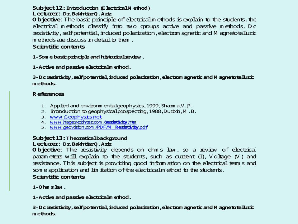
Subject 12: Introduction (Electrical Method) Lecturer: Dr. Bakhtiar Q. Aziz Objective: The basic principle of electrical methods is explain to the students, the electrical methods classify into two groups active and passive methods. Dc resistivity, self potential, induced polarization, electromagnetic and Magnetotelluric methods are discuss in detail to them. Scientific contents
1- Some basic principle and historical review.
1- Active and passive electrical method.
3- Dc resistivity, self potential, induced polarization, electromagnetic and Magnetotelluric methods.
References
1. Applied and environmental geophysics, 1999, Sharma,V.,P. 2. Introduction to geophysical prospecting, 1988, Durbin, M. B. 3. www.Geophysics.net 4. www.hager-richter.com/resistivity.htm 5. www.geovision.com/PDF/M_Resistivity.pdf
Subject 13: Theoretical background Lecturer: Dr. Bakhtiar Q. Aziz Objective: The resistivity depends on ohms law, so a review of electrical parameters will explain to the students, such as current (I), Voltage (V) and resistance. This subject is providing good information on the electrical terms and some application and limitation of the electrical method to the students. Scientific contents
1- Ohms law.
1- Active and passive electrical method.
3- Dc resistivity, self potential, induced polarization, electromagnetic and Magnetotelluric methods.
Electrical Method
Prepared By
BAKHTIAR QADER AZIZ
2010-2011B.Sc
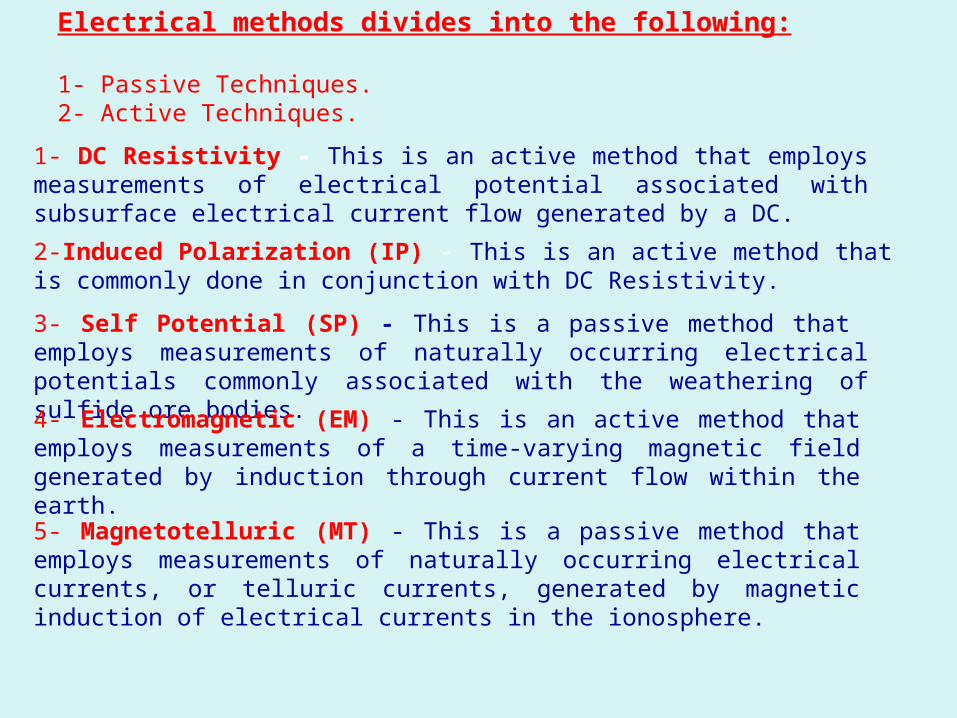
Electrical methods divides into the following:
1- Passive Techniques.2- Active Techniques.
1- DC Resistivity - This is an active method that employs measurements of electrical potential associated with subsurface electrical current flow generated by a DC.2-Induced Polarization (IP) - This is an active method that is commonly done in conjunction with DC Resistivity. 3- Self Potential (SP) - This is a passive method that employs measurements of naturally occurring electrical potentials commonly associated with the weathering of sulfide ore bodies. 4- Electromagnetic (EM) - This is an active method that employs measurements of a time-varying magnetic field generated by induction through current flow within the earth.
5- Magnetotelluric (MT) - This is a passive method that employs measurements of naturally occurring electrical currents, or telluric currents, generated by magnetic induction of electrical currents in the ionosphere.
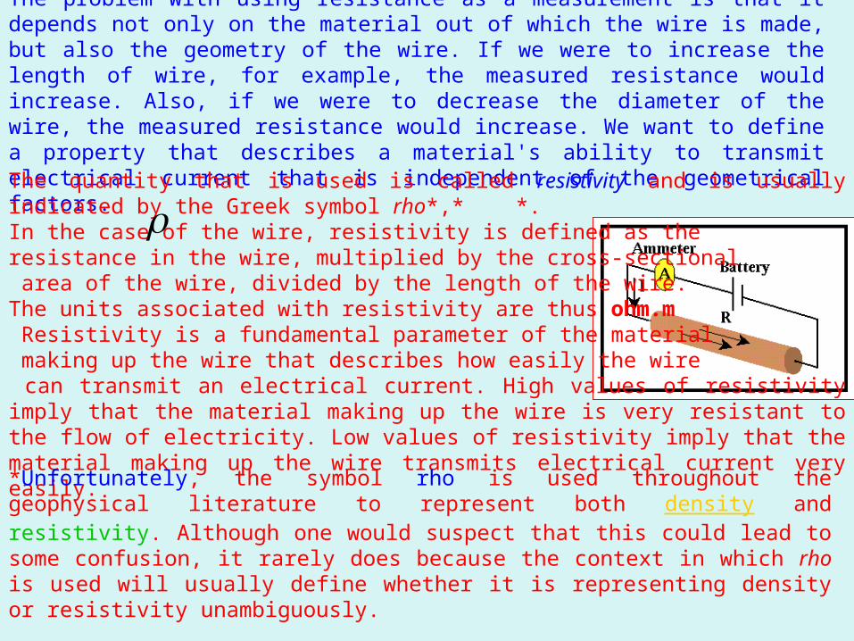
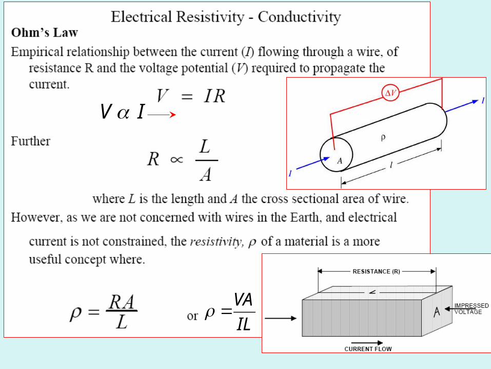
It's Resistivity, not ResistanceThe problem with using resistance as a measurement is that it depends not only on the material out of which the wire is made, but also the geometry of the wire. If we were to increase the length of wire, for example, the measured resistance would increase. Also, if we were to decrease the diameter of the wire, the measured resistance would increase. We want to define a property that describes a material's ability to transmit electrical current that is independent of the geometrical factors. The quantity that is used is called resistivity and is usually indicated by the Greek symbol rho*,* *. In the case of the wire, resistivity is defined as the resistance in the wire, multiplied by the cross-sectional area of the wire, divided by the length of the wire. The units associated with resistivity are thus ohm.m Resistivity is a fundamental parameter of the material making up the wire that describes how easily the wire can transmit an electrical current. High values of resistivity imply that the material making up the wire is very resistant to the flow of electricity. Low values of resistivity imply that the material making up the wire transmits electrical current very easily. *Unfortunately, the symbol rho is used throughout the geophysical literature to represent both density and resistivity. Although one would suspect that this could lead to some confusion, it rarely does because the context in which rho is used will usually define whether it is representing density or resistivity unambiguously.
Electrical Resistivity1- FundamentalsThe electrical resistivity method is used to map the subsurface electrical resistivity structure, which is interpreted by the geophysicist to determine geologic structure and/or physical properties of the geologic materials. The electrical resistivity of a geologic unit or target is measured in ohmmeters, and is a function of porosity, permeability, water saturation and the concentration of dissolved solids in pore fluids within the subsurface.The purpose of a DC electrical survey is to determine the subsurface resistivity distribution of the ground, which can then be related to physical conditions of interest such as lithology, porosity, the degree of water saturation, and the presence or absence of voids in the rock. The basic parameter of a DC electrical measurement is resistivity. Resistivity is not to be confused with resistance.2- AdvantagesA principal advantage of the electrical resistivity method is that quantitative modeling is possible using either computer software or published master curves. The resulting models can provide accurate estimates of depth, thickness and electrical resistivity of subsurface layers. The layered electrical resistivities can then be used to estimate the electrical resistivity of the saturating fluid, which is related to the total concentration of dissolved solids in the fluid.
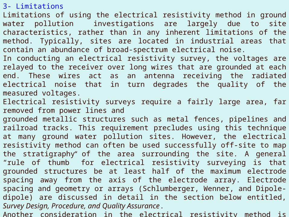
3- LimitationsLimitations of using the electrical resistivity method in ground water pollution investigations are largely due to site characteristics, rather than in any inherent limitations of the method. Typically, sites are located in industrial areas that contain an abundance of broad-spectrum electrical noise.In conducting an electrical resistivity survey, the voltages are relayed to the receiver over long wires that are grounded at each end. These wires act as an antenna receiving the radiated electrical noise that in turn degrades the quality of the measured voltages.Electrical resistivity surveys require a fairly large area, far removed from power lines andgrounded metallic structures such as metal fences, pipelines and railroad tracks. This requirement precludes using this technique at many ground water pollution sites. However, the electrical resistivity method can often be used successfully off-site to map the stratigraphy of the area surrounding the site. A general “rule of thumb” for electrical resistivity surveying is that grounded structures be at least half of the maximum electrode spacing away from the axis of the electrode array. Electrode spacing and geometry or arrays (Schlumberger, Wenner, and Dipole-dipole) are discussed in detail in the section below entitled, Survey Design, Procedure, and Quality Assurance.Another consideration in the electrical resistivity method is that the fieldwork tends to be more labor intensive than some other geophysical techniques. A minimum of three crewmembers is required for the fieldwork.
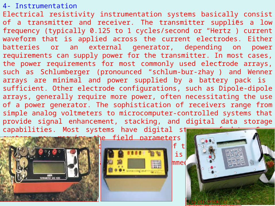
4- InstrumentationElectrical resistivity instrumentation systems basically consist of a transmitter and receiver. The transmitter supplies a low frequency (typically 0.125 to 1 cycles/second or “Hertz”) current waveform that is applied across the current electrodes. Either batteries or an external generator, depending on power requirements can supply power for the transmitter. In most cases, the power requirements for most commonly used electrode arrays, such as Schlumberger (pronounced “schlum-bur-zhay”) and Wenner arrays are minimal and power supplied by a battery pack is sufficient. Other electrode configurations, such as Dipole-dipole arrays, generally require more power, often necessitating the use of a power generator. The sophistication of receivers range from simple analog voltmeters to microcomputer-controlled systems that provide signal enhancement, stacking, and digital data storage capabilities. Most systems have digital storage of data. Some systems may require the field parameters to be input via PC (personal computer) prior to collection of the data. The trend in manufacturers of resistivity equipment is to have the entire system controlled form a PC or preprogrammed software built into the instrument.
Fig (1) SYSCAL Jr Switch-72 resistivity meter
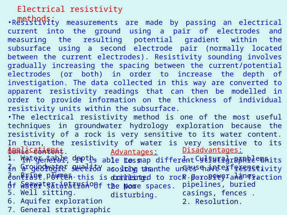
Electrical resistivity methods:•Resistivity measurements are made by passing an electrical current into the ground using a pair of electrodes and measuring the resulting potential gradient within the subsurface using a second electrode pair (normally located between the current electrodes). Resistivity sounding involves gradually increasing the spacing between the current/potential electrodes (or both) in order to increase the depth of investigation. The data collected in this way are converted to apparent resistivity readings that can then be modelled in order to provide information on the thickness of individual resistivity units within the subsurface. •The electrical resistivity method is one of the most useful techniques in groundwater hydrology exploration because the resistivity of a rock is very sensitive to its water content. In turn, the resistivity of water is very sensitive to its ionic content.• In general, it is able to map different stratigraphic units in a geologic section as long as the units have a resistivity contrast. Often this is connected to rock porosity and fraction of water saturation of the pore spaces.Applications:1. Water table depth.2. Groundwater quality3. Brine plumes.4. Seawater intrusion5. Well sitting.6. Aquifer exploration7. General stratigraphic mapping
Advantages:1. Less costly than drilling.2. Non disturbing.
Disadvantages:1. Cultural problems cause interference, e.g., power lines, pipelines, buried casings, fences .2. Resolution.
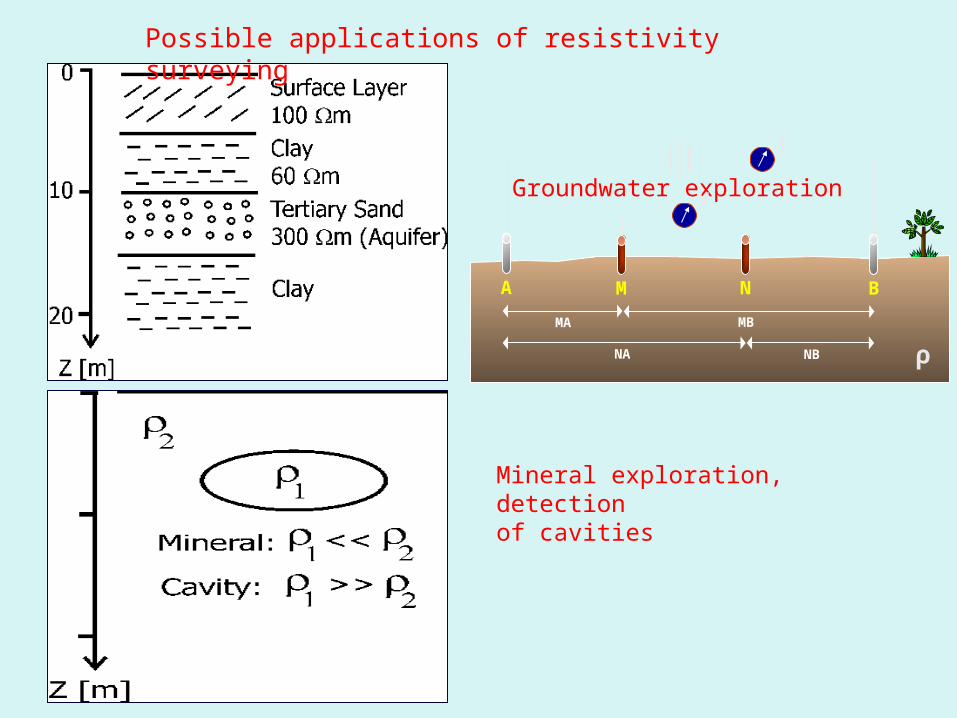
Possible applications of resistivity surveying
Groundwater exploration
Mineral exploration, detectionof cavities
V
I
A M N BMA MB
NA NB ρ
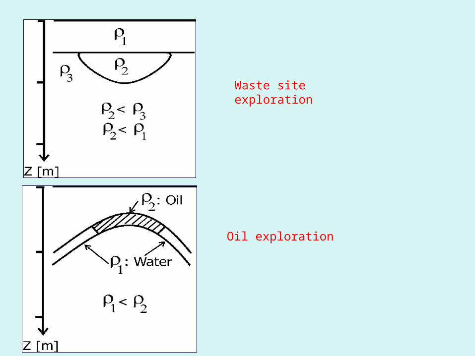
Waste site exploration
Oil exploration
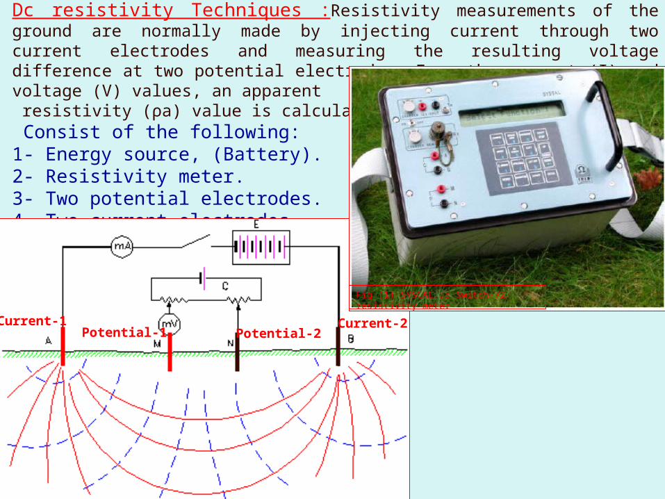
Dc resistivity Techniques :Resistivity measurements of the ground are normally made by injecting current through two current electrodes and measuring the resulting voltage difference at two potential electrodes. From the current (I) and voltage (V) values, an apparent resistivity (ρa) value is calculated, Consist of the following:1- Energy source, (Battery).2- Resistivity meter.3- Two potential electrodes.4- Two current electrodes.
Current-1 Current-2Potential-1 Potential-2
Fig (1) SYSCAL Jr Switch-72 resistivity meter
IV
ILVA
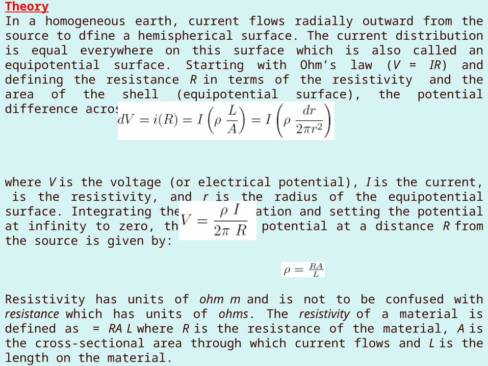
TheoryIn a homogeneous earth, current flows radially outward from the source to dfine a hemispherical surface. The current distribution is equal everywhere on this surface which is also called an equipotential surface. Starting with Ohm’s law (V = IR) and defining the resistance R in terms of the resistivity and the area of the shell (equipotential surface), the potential difference across the shell is
where V is the voltage (or electrical potential), I is the current, is the resistivity, and r is the radius of the equipotential surface. Integrating the above equation and setting the potential at infinity to zero, the electric potential at a distance R from the source is given by:
Resistivity has units of ohm m and is not to be confused with resistance which has units of ohms. The resistivity of a material is defined as = RA L where R is the resistance of the material, A is the cross-sectional area through which current flows and L is the length on the material.The potential has been derived due to a single current source. The goal in resistivity surveying is to measure the potential different between two points due to the current from two current electrodes. The potential at each electrode is determined due to the current sources:
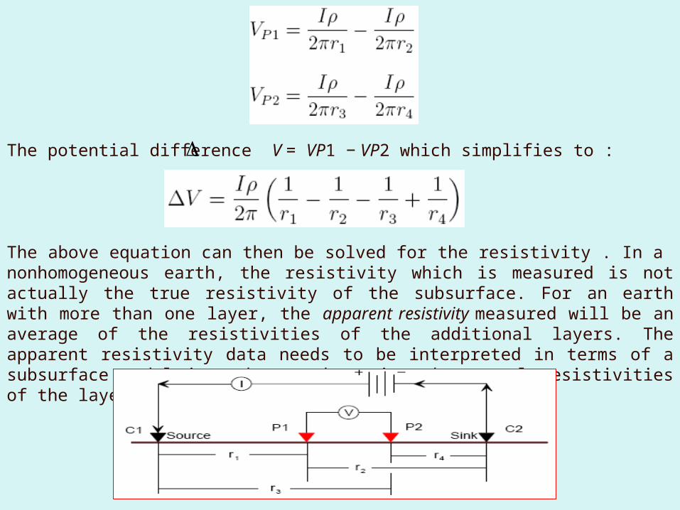
The potential difference V = VP1 − VP2 which simplifies to :
The above equation can then be solved for the resistivity . In a nonhomogeneous earth, the resistivity which is measured is not actually the true resistivity of the subsurface. For an earth with more than one layer, the apparent resistivity measured will be an average of the resistivities of the additional layers. The apparent resistivity data needs to be interpreted in terms of a subsurface model in order to determine the actual resistivities of the layers.
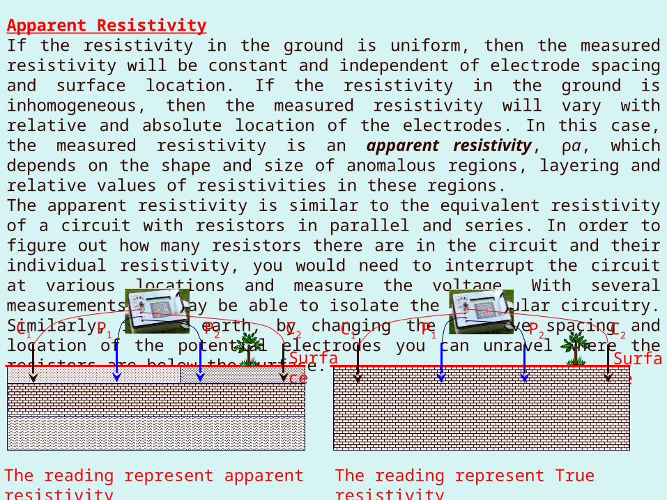
Apparent ResistivityIf the resistivity in the ground is uniform, then the measured resistivity will be constant and independent of electrode spacing and surface location. If the resistivity in the ground is inhomogeneous, then the measured resistivity will vary with relative and absolute location of the electrodes. In this case, the measured resistivity is an apparent resistivity, ρa, which depends on the shape and size of anomalous regions, layering and relative values of resistivities in these regions.The apparent resistivity is similar to the equivalent resistivity of a circuit with resistors in parallel and series. In order to figure out how many resistors there are in the circuit and their individual resistivity, you would need to interrupt the circuit at various locations and measure the voltage. With several measurements you may be able to isolate the particular circuitry. Similarly, in the earth, by changing the relative spacing and location of the potential electrodes you can unravel where the resistors are below the surface.
Surface
Surface
C1 C2P1 P2 C1 C2P1 P2
The reading represent apparent resistivity
The reading represent True resistivity
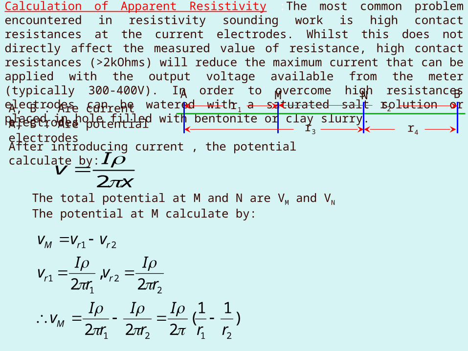
Calculation of Apparent Resistivity :The most common problem encountered in resistivity sounding work is high contact resistances at the current electrodes. Whilst this does not directly affect the measured value of resistance, high contact resistances (>2kOhms) will reduce the maximum current that can be applied with the output voltage available from the meter (typically 300-400V). In order to overcome high resistances electrodes can be watered with a saturated salt solution or placed in hole filled with bentonite or clay slurry.
A BM N r2r1
r3 r4
A, B : Are current electrodesA, B : Are potential electrodesAfter introducing current , the potential calculate by:
xIv
2
The total potential at M and N are VM and VNThe potential at M calculate by:
)11(222
2,
2
2121
22
11
21
rrI
rI
rIv
rIv
rIv
vvv
M
rr
rrM
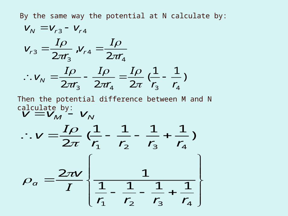
By the same way the potential at N calculate by:
)11(222
2,
2
4343
44
33
43
rrI
rI
rIv
rIv
rIv
vvv
N
rr
rrN
Then the potential difference between M and N calculate by:
4321
4321
111112
)1111(2
rrrrIv
rrrrIv
vvv
a
NM
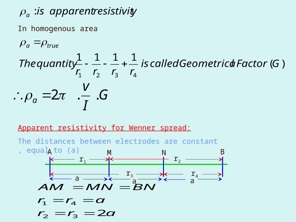
)(1111
:
4321
GFactorlGeometricacalledisrrrr
quantityThe
yresistivitapparentis
truea
a
GIv
a ..2
In homogenous area
Apparent resistivity for Wenner spread:The distances between electrodes are constant , equal to (a)A BM N r2r1
r3 r4a a a
arrarr
BNMNAM
232
41
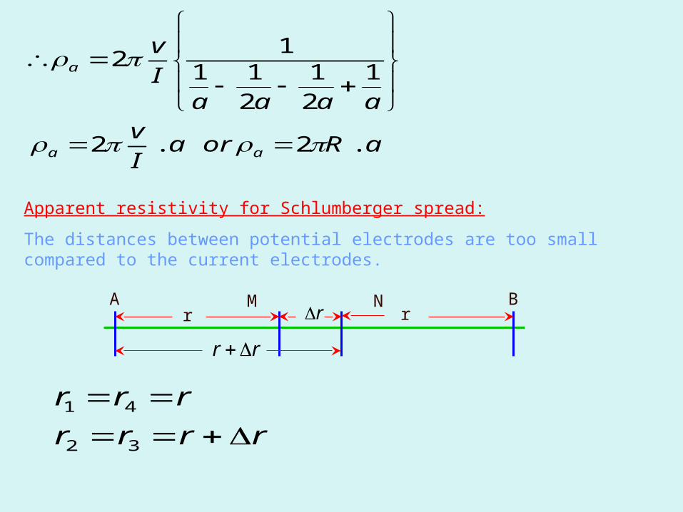
aRoraIv
aaaaIv
aa
a
.2.2
121
211
12
Apparent resistivity for Schlumberger spread:The distances between potential electrodes are too small compared to the current electrodes.
A BM N rr r
rr
rrrrrrr
32
41
MNAMR
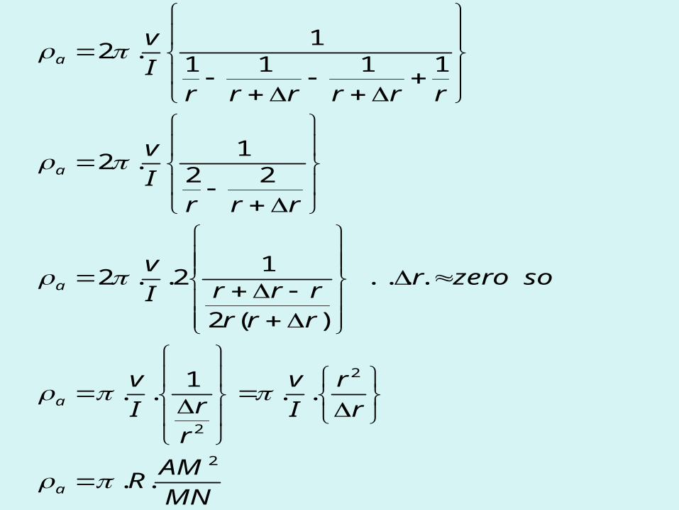
rr
Iv
rrI
v
sozeror
rrrrrrI
v
rrrIv
rrrrrrIv
a
a
a
a
a
2
2
2
..
..1..
....
)(2
12..2
221.2
11111.2